Download USER MANUAL
Transcript
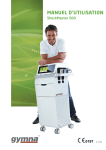
USER MANUAL
ShockMaster 500
0197
V 1.4
2
Copyright Uniphy Elektromedizin GmbH & Co. KG 2011.
ShockMaster is a registered trademark of GymnaUniphy.
Unauthorised reproduction, either in whole or part, of the software
provided with this product is strictly prohibited and is subject to prosecution.
All rights reserved.
ShockMaster 500 is manufactured in Germany
by Uniphy Elektromedizin GmbH & Co. KG
Neuendorfstraße 19 b
D-16761 Hennigsdorf - Germany
T +49 (0) 3302 5044-0
F +49 (0) 3302 5044-99
[email protected] - [email protected]
www.shockmaster.eu
3
Content
4
1. General Information
1.1
Introduction
1.1.1 Indications
1.1.2 Contra-indications
1.1.3 Side effects
1.2
Prerequisites for operating the ShockMaster 500
1.2.1 Operator
1.2.2 Training of the operator
1.3
Description of controls and functional elements
1.4
Description of used marks and symbols
6
6
8
8
9
9
9
9
11
13
2. Installation
2.1
Unpacking
2.2
Scope of supply
2.2.1 Connecting the compressed air supply
2.2.2 Connecting the power supply cables
2.2.3 Hand piece connection
14
14
14
15
16
17
3. Operation
3.1
General warnings and safety information
3.2
Operation
3.2.1 The user interface
3.2.1.1 Introduction
3.2.1.2 Treatment screen
3.2.1.2.1 Parameters
3.2.1.2.2 Graphic representation of an uploaded indication
3.2.1.3 Indications list
3.2.1.4 Body area
3.2.1.5 Patient database
3.2.1.6 Anatomical library screen
3.2.1.7 Settings screen
3.2.1.8 Software update
3.3
Start-up
3.4
Functional checks
3.5
Standard settings
3.6
Treatment
18
18
21
21
21
23
23
25
27
30
31
35
36
38
40
40
41
42
4. Cleaning, Maintenance and Overhaul
4.1
Cleaning
4.2
Replacement mains fuse
4.3
Maintenance
4.4
Disposal
4.5
Repair
42
43
44
45
45
45
5. Status messages and trouble-shooting
5.1
Status messages
5.2
Trouble shooting
46
46
46
6. Accessories and spare parts
6.1
ShockMaster 500
6.2
Compressor
6.3
Accessories
6.4
Documentation
48
48
48
49
49
7. Technical specifications
7.1
ShockMaster 500
7.2
Identification plate ShockMaster 500
7.3
Conformity with directives
7.4
Conformity with standards
7.5
Directives
50
50
51
51
51
56
8. Warranty and service
8.1
Warranty
8.2
Service
57
57
57
Attachment
58
Compressor-Installation
60
5
1. General Information
1.1 Introduction
This manual contains warnings, safety instructions and specific operating instructions in accordance with
liability regulations.
CAUTION
Complete or partial failure to observe the instructions, information or procedures preceded by the term “CAUTION” may cause injury or fatal accidents.
ATTENTION
Complete or partial failure to observe the instructions, information or procedures preceded
by the term “ATTENTION” may cause equipment damage.
NOTE
Additional information concerning specific features or operating instructions is preceded
by the term “NOTE”.
!
!
!
6
!
CAUTION
Before you start using the ShockMaster 500 for the first time, please make sure you have read and understood all information provided in this operating
manual.
Familiarity with the information and instructions contained in this manual is an essential requirement to ensure efficient and optimal use of the system, to avoid dangers to persons and to the equipment and to obtain good treatment results.
Thorough knowledge of the information included in this manual will also enable you to react promptly and effectively in case of malfunctions and failures.
When using optionally available accessories, please also refer to the separate operating manuals for each of these accessories. Knowledge of the content of this manual is an essential prerequisite for operating the entire system.
The ShockMaster 500 is a compressed air operated ballistic shockwave generator featuring high-precision
ballistic components in its applicator for shockwave generation. The motion and weight of the projectile
accelerated by compressed air produce kinetic energy that is converted into sound energy when the
projectile strikes an unmoved surface (shock transmitter). This acoustic pulse is transmitted to the target
tissue directly as well as by means of an acoustic impedance adapter (shockwave coupling cushion) or gel.
These waves are physically classified as radial pressure waves. The applied pressure pulse propagates
radial within the tissue and has a therapeutic effect on areas of the tissue near the surface, in particular.
!
NOTE
Medical devices operating on the basis of the above principle are generally referred to
as extracorporeal shockwave systems in modern medical literature.
7
1.1.1 Indications
The ShockMaster 500 is designed for extracorporeal treatment by means of low- to medium-energy radial
shockwaves.
Indications include:
• Biomechanical therapy
• Myofascial trigger points (MTrP)
• Disorder of tendon insertions
• Activation of muscle and connective tissue
• Acupuncture shockwave therapy
Qualified training in acupuncture and acupuncture shockwave therapy (AkuST) is required for therapeutic
application of the ShockMaster 500 in the field of acupuncture.
A sound knowledge of trigger point therapy and trigger point shockwave therapy (TrST) is required for
therapeutic application of the ShockMaster 500 in the field of trigger point shockwave therapy.
1.1.2 Contra-indications
!
CAUTION
The contraindications listed here are examples. No claims are made regarding the completeness or unlimited validity of this list of contraindications.
Treatment with the ShockMaster 500 is not permitted in the following cases:
• coagulation disorders (haemophilia)
• use of anticoagulants, especially Marcumar
• thrombosis
• tumour diseases, carcinoma patients
• pregnancy
• polyneuropathy in case of diabetes mellitus
• acute inflammations / pus focus in the target area
• children in growth
• cortisone therapy up to 6 weeks before first treatment
8
!
CAUTION
Shockwaves must not be applied to target areas located above air filled
tissue (lungs), nor to any regions near large nerves, vessels, the spinal column or head.
1.1.3 Side effects
Treatment with the ShockMaster 500 may cause the following side effects:
• swelling, reddening, haematomas
• petechiae, pain
• skin lesions after previous cortisone therapy
These side effects generally abate after 5 to 10 days.
1.2 Prerequisites for operating the ShockMaster 500
1.2.1 Operator
The ShockMaster 500 is intended exclusively for use by (para)medical specialists or physiotherapists and is
only allowed to be used by qualified and instructed medical persons. Such a specialist is expected to have
practical knowledge of medical procedures and applications as well as of the technology, and should be
experienced in treating the indications stated in chapter 1.1.1. The specialist must have the basic physical and cognitive prerequisites such as vision, hearing and reading. Furthermore, the basic functions of
the upper extremities must be guaranteed. The device is designed for a demographic target group between 18 and 65 years.
1.2.2 Training of the operator
Operators of the ShockMaster 500 must have been adequately trained in using this system safely and
efficiently before they operate the device described in this handbook. An introduction to the principles of
operation is provided by the GymnaUniphy dealer with reference to the operating manual.
9
The operator must be instructed in the following points:
• Instruction in operation and designated use of the device with practical exercises
• Mode of effect and function of the device and the applied energies
• Settings of all components
• Indications for use of the device
• Contra-indications and side effects of the therapy waves
• Explanation of the warning notes in all operating statuses
• Instruction in how to perform the functional checks.
Further training requirements vary from country to country. It is the operator’s responsibility to ensure that
the training meets the requirements of all applicable local laws and regulations.
Other information about training in the operation of this system can be obtained from your GymnaUniphy
dealer.
However, you can also contact the following address directly:
GYMNA-UNIPHY NV
Pasweg 6A
3740 Bilzen
België
T: +32(0) 89 510.510
F: +32 (0) 89 510.511
[email protected]
10
1.3 Description of controls and functional elements
1
2
3
4
1.
2.
3.
4.
LCD TFT Touch Screen
Connector R-SW/V-ACTOR hand piece channel black
Connector R-SW/V-ACTOR hand piece channel yellow
R-SW hand piece
1
2
1. Connector R-SW/V-ACTOR hand piece channel black
2. Connector R-SW/V-ACTOR hand piece channel yellow
11
6
5
4
3
2
7
8
1
1.
2.
3.
4.
5.
6.
7.
8.
12
USB connector (Type A)
Compressed air connector
Auxiliary outlet (line out for compressor)
Mains connector
Mains fuse holder
Mains switch
Label 5A max.
Read the manual first
1.4 Description of used marks and symbols
see attachment pag. 59
13
2. Installation
2.1 Unpacking
•
•
•
•
Remove the equipment and accessories from the packaging container. Proceed with extreme caution
Check that all items are included in the packaging container and that they are not damaged.
Contact your supplier or the manufacturer immediately if any items are missing or damaged.
Retain the original packaging, if possible. It may prove useful for any later equipment transport.
2.2 Scope of supply
The standard scope of supply of the ShockMaster 500 includes the following items:
•
•
•
•
•
•
•
•
•
•
•
•
•
ShockMaster 500 (device + trolley)
Complete R-SW hand piece + gel holder
Mains cable
Gel bottle
Handle bar
RSW hand piece
15 mm Classic applicator
20 mm D-ACTOR® applicator
User manual of the ShockMaster 500 (hard copy in English, other languages available on CD)
Compressor
Revision kit
User manual of the compressor (hard copy in English)
User manual of the hand piece (hard copy in English)
Please refer to chapter 6 for information on ACCESSORIES AND SPARE PARTS
14
2.2.1 Connecting the compressed air supply
ATTENTION
The compressed air input pressure must be 6.0 - 7.0 bar. If compressors other than the GymnaUniphy S.A. 50 TDC compressor are used, this pressure must be checked on the compressed air supply system.
If the pressure exceeds 7.0 bar the system‘s overpressure protection will be tripped.
The compressed air must be dry, oil-free and filtered to ≤ 5 micron. Never use CO2 gas
for compressed air supply. If compressed air is supplied through a wall outlet, use a
pressure reducer (max. 7 bar), if necessary.
!
•
Connect the compressed air tube to the compressed air connector provided on the compressor.
•
Connect the compressed air tube to the compressed air tube connector provided on the rear side
of the ShockMaster 500 until it audibly engages.
15
!
ATTENTION
When setting up the unit, make sure that the air outlets on the housing of the
ShockMaster 500 are not blocked.
2.2.2 Connecting the power supply cables
An external compressor has to be controlled by the ShockMaster 500 via the mains power link cable.
(Compressor Installation: see page 58)
•
•
Connect the compressor via the mains power link cable to the auxiliary outlet of the ShockMaster 500. (1)
Connect the ShockMaster 500 via the mains cable to the mains connector. (2)
2
!
16
1
ATTENTION
Use both power connectors only for connecting the compressor (1) or Shockmaster 500 (2).
Do not connect any other electrical equipment.
!
NOTE
The compressor is automatically switched on and off with the ShockMaster 500.
During first installation make sure that the mains switch of the compressor is in ON position.
2.2.3 Hand piece connection
•
Connect the connector of the R-SW hand piece to the hand piece connector provided on the
ShockMaster 500.
!
•
•
ATTENTION
Consider the colour marks. Connect the hand piece with the black mark on the cable only with the black output channel. The yellow channel can be used for an extra hand piece or
a V-ACTOR®.
Make sure that the red spots on the connector match the red spots on the hand piece connector.
Place the hand piece in the hand piece holder.
!
NOTE
Please refer to the separate operating instructions of the hand piece.
17
3. Operation
3.1 General warnings and safety information
!
18
CAUTION
The ShockMaster 500 is exclusively intended for use by medical specialists and must only be used by suitably qualified and trained medical personnel (see also chapter 1.2 PRECONDITIONS TO OPERATE THE ShockMaster 500)
The user is responsible for correctly positioning the hand piece of the
ShockMaster 500.
It is the user’s responsibility to determine correctly where the treatment zone is located.
The ShockMaster 500 must only be used for applications approved by
GymnaUniphy.
To avoid safety hazards, use of the system for applications other than those specified in chapter 1.1.1 INDICATIONS is not allowed!
Do not use the ShockMaster 500 in potentially explosive environments, i.e.
in the presence of a flammable anaesthetic mixture with air or with oxygen or nitrous oxide.
If systems other than medical devices in accordance with EN 60602 are
connected to the ShockMaster 500, such systems must be installed outside
the patient treatment area.
Cleansing and disinfecting agents may generate an explosive atmosphere.
Disconnect the unit and the accessories from the mains before starting any
cleaning and overhauling work!
Do not try to open the system! Risk of electric shocks!
!
ATTENTION
The unit is movable by a trolley on spot. Take care for transport that the wheels are not blocked (by brake or any parts on the floor) and do not push the unit!
19
ATTENTION
Check that the installation surfaces have sufficient carrying capacity to avoid
equipment damage!
Electric medical devices underlie special regulations regarding Electromagnetic
Compatibility (EMC). Hence, medical electric devices have to be installed and
commissioned in accordance with the EMC guidelines detailed in the accompanying
documents.
Portable and mobile HF communications equipment (such as cell phones) may cause
interferences with medical electric devices.
The use of accessories or cabling not authorised by the supplier may cause
increased emissions or may lead to reduced interference resistance of the device.
The ShockMaster 500 must neither be deployed nor stored together with
other devices. If the operation near or jointly with other devices is required, the
ShockMaster 500 has to be tested against that particular environment to ensure
operation according to technical specification.
The ShockMaster 500 may be deployed and operated close to the listed accessories.
The system must only be connected to properly earthed and correctly installed
shockproof sockets!
Check that the system is in perfect working order before each use, see chapter
3.4 FUNCTIONAL CHECKS.
Never cover the system when in use!
Make absolutely sure that no liquid can seep into the system housing or hand piece.
Any damage to the unit resulting from incorrect operation is not covered by the
manufacturer’s warranty.
Disposal of the system and its components must be carried out in accordance with
national waste disposal regulations.
ShockMaster 500 must only be used with accessories that have been approved
by the system manufacturer. To prevent safety hazards, unauthorized system
modifications are not allowed. This will void the CE mark approval and warranty.
!
20
NOTE
The ShockMaster 500 meets the requirements of the applicable
electromagnetic compatibility (EMC) standards EN 60602-1-2.
These limits are designed to provide reasonable protection against harmful interference
in a typical medical installation. The equipment generates, uses and can radiate radio
frequency energy. If not installed and used in accordance with these instructions, the equipment may cause harmful interference to other devices in the vicinity. However, there
is no guarantee that interference will not occur in a particular installation. If this equipment does cause harmful interference with other devices, which can be determined by turning the equipment off and on, the user is encouraged to try to correct the interference by one or more of the following measures:
!
Reorient or relocate the receiving device
Increase the separation between the equipment
Connect the equipment into an outlet on a circuit different from that to hich
the other device is connected
Consult the manufacturer of field service technician for help
3.2 Operation
The ShockMaster 500 is operated by using a color LCD monitor with touch-screen function.
3.2.1 The user interface
3.2.1.1Introduction
The user interface is divided into 1 main-screen ( treatment-screen) and 5 menu-screens.
When switching on the device, you automatically enter the main screen (treatment screen)..
You can use the 5 control buttons at the bottom of the screen to display a menu. The selected control
button will turn blue and the requested menu is activated. To leave the menu, push the control button again.
21
22
Control button to activate the “Indications List” screen
Control button to activate the “Body Areas” screen.
Control button to activate “Patients Database” screen
Control button to activate “ Anatomical Library” screen
Control button to activate “Settings” screen.
3.2.1.2Treatment screen
The treatment-screen consists of 2 parts.
At the right-hand side of the treatment screen the parameters are shown.
You can upload a pre-programmed set of parameters from the list of indications ( please check chapter 3.2.1.3
Indications list)
For each indication there is a graphical representation of the treatment.
When loading an indication the graphical representation will appear on the left-hand side of the treatment
screen.
3.2.1.2.1
Parameters
23
The following parameters can be set:
•
Pressure : 1-5 bar
Adjustable by steps of 0.1 bar
•
Number of shocks : 1-20000 shocks adjustable by steps of :
- 1 shock between 1-10 shocks
- 10 shocks between 10-100 shocks - 100 shocks between 100-20000 shocks.
- unlimited amount of shocks
•
Frequency:
0.5-21Hz (V-ACTOR® 0,5-35Hz) adjustable by steps of :
- 0.5Hz for a frequency lower then 10Hz
- 1Hz for a frequency higher then 10Hz
The frequency of 35 Hz can be set at any moment but will only be active when using the V-ACTOR®.
If you use the hand piece, the frequency will be automatically reset to 21 HZ, the maximum frequency
for the use of the hand piece.
With the reset button you can reset the number of actual shocks to 0.
A pop-up screen will appear and you can confirm or cancel.
During the treatment you can adjust the parameters.
During the treatment you can NOT activate another menu..
24
Below the parameter “Number of shocks” is a bar with LEDs. On this bar, LEDS will light up to indicate (in %)
how many shocks of the total number of shocks assigned have already been given.
3.2.1.2.2
Graphic representation of an uploaded indication
When loading an indication (see p 29) the corresponding image will show up at the left part of the
treatment screen.
!
NOTE
The pre-programmed parameter-settings (indications) are based on experiences from
medical experts or physiotherapists. These are indicative and can be used as an example but
can be adjusted to own expertise.
Attention: at own risk of the operator!
25
At the end of treatment the following question will pop up : “Save session? ”
Here you can choose to save the data of the session in your patient database
(Note : only when you have selected a patient, see p 33)
These data will be saved :
• Date of treatment
• Name of the indication which was loaded
• Selected parameters (If the parameters have been changed after the loading of the indication the
changed values will be saved)
• VAS score (see p 33)
26
3.2.1.3 Indications list
The first button is the “Indications List”
An indication consists of pre-programmed parameter-settings and an image illustrating the treatment.
On top of the Indications list you can find the following buttons :
• Free:
Deselect the previous selected indication. You will automatically be redirected to the treatment-screen.
The parameters of the previous selected indication are gone and there is no image on the left side of the
treatment-screen.
• New:
Add a new indication.
A new screen will appear. In this screen you can name the new indication, set the corresponding
parameters and add extra remarks.
27
Press “OK” or “Cancel” to leave this screen.
The new indication will only appear in the “Indications list” when you have saved by pressing “OK”.
New indications are, in alphabetical order, visible at the end of the list of standard indications.
28
At the right side of the Indication-screen you can find the following buttons :
• Info:
This screen will provide you with more detailed information about the indication you have selected.
The info is divided into 3 elements :
- Treatment Protocol Phase 1
- Treatment Protocol Phase 2
- Medical information
29
With the buttons at the bottom of the screen you can browse between the 3 pages. Press “Close” to leave the
info-screen..
•
Load :
The indication you have selected will be loaded and the treatment-screen will pop up automatically. The name of
the indication you have selected will come into sight at the left upper corner of the screen. The parameters are set
and at the left-handed side of the screen the corresponding image(s) will become visible
•
Edit :
A screen, similar to the “New Indication”-screen, will be opened. All data are already filled out. These date can be
modified now. You can only change indications you have added yourself. The standard indications can not be
modified.
•
Delete :
Only the indications you have added yourself can be deleted.
Standard indications can not be deleted.
A pop up screen will ask for a confirmation.
You can confirm or cancel.
3.2.1.4Body area
The 2nd menu is the “Body Area” menu. The buttons are linked to several body areas. Every body area
contains several indications. After selecting a body area, a pop-up screen will appear.
30
Every indication is supported with an anatomical image related to the muscle area of the indication.
Select the desired indication, and select “ok”. The program immediately goes to the Treatment Menu.
No indication can be added or deleted.
There is no possibility to check more information of a selected indication. Also there is no possibility to
activate the “free mode”.
3.2.1.5 Patient database
The 3rd menu is the “Patient database”.
It looks and operates quiet similar as the Indication menu
31
On top of the Indications list you can find the following buttons
• Free:
Deselect the previous loaded patient.
You return automatically to the treatment menu.
• New:
Add a patient. A new screen appears. In this screen, you can add the patients’ name, address
or extra remarks
Remark: You can only use 25 characters for adding the name of the patient
Confirm with “OK” to leave this screen
The new patient will be added to the list when pressing “OK”.
32
Following buttons are at the right of the patient list:
• Info:
The screens give all information on the selected patient:
The information is shown in 3 screens:
- General information on the patient
- List of saved treatment data.
- VAS scores of the selected treatment in screen 2 are shown in a graphic.
This graphic shows the progression of the treatment.
33
• Load:
Load the selected patient.
A pop-up with the VAS (visual analog scale) automatically opens to evaluate the therapy based on the
pain of the patient.
A VAS is a pain measurement instrument that tries to measure a characteristic or attitude that is believed to
range across a continuum of values and cannot easily be directly measured.
Operationally a VAS is usually a horizontal line, 100mm in length. The patient marks on the line the point that
they feel represents their perception of their current state.
After filling in the VAS score, you automatically go to the treatment screen.
The name of the selected patient appears in the middle of the treatment screen.
After ending the treatment, a pop-up appears to save the data of the treatment. These data will be available
in the info (look at the top of this section)
• Edit:
A similar screen as ‘new patient’ but all data are already filled in. These data can be edited.
• Delete:
Delete the selected patient. A pop-up screen appears asking
to delete the patient “yes” or “No”.
34
3.2.1.6 Anatomical library screen
The 4th menu is the “Anatomical Library”.
Access the anatomical library for anatomical information on the musculoskeletal system. Select the body area
you want to display information of. After selecting a pop-up screen will appear. This information is only in
English available.
Select an item from the list and push “ Ok”. Detailed anatomical information will pop-up.
You can go back to the Anatomical Library by selecting “ Close”.
35
If you select a muscle the following information is available:
-
Origin
-
Insertion
-
Action
-
Innervation
-
Arterial Supply
If you select a ligament or joint, an anatomical picture with detailed information will pop-up.
3.2.1.7 Settings screen
The 5th menu is the “Settings” screen.
In this menu, all device settings can be changed.
36
The menu structure is as follows:
1
General info
Software version number.
Critical parts of the device
2
Languages
German
English
Spanish
French
Italian
Dutch
Turkish
Danish
Czech
Polish
Russian
Portuguese
Swedisch
Norwegian
3
Time
Date and time
4
Hand piece counter Black
- Number of shocks on channel Black
- Reset button to put on 0
5
Hand piece counter Yellow
- Number of shocks on channel Yellow
- Reset button to put on 0
6
V-ACTOR® counter
- Number of shocks done by the V-Actor®
- Reset button to put on 0
7
Software update
1.
2.
3.
4.
Click on the update button.
Insert the memory stick.
Wait until update finished.
Release the memory stick and restart the
device.
37
3.2.1.8 Software update
1. Start up the device and go to the setting screen
Push on the settings button
Start the update:
Select “Software update”.
The following screen appears:
3. Prepare the ShockMaster to receive data
Push on the “Update” button until a small white arrow appears.
You also here a “click” inside the unit.
Now the unit is ready for the update
38
4. Transfer data.
Insert the memory stick where you have placed on the software update.
After a few seconds a popup will be displayed.
5. Finish transfer data
Wait until the update is finished
6. Check if you have the correct version loaded
Release the memory stick and restart the device.
Check if the version is correct.
Push the settings button and select “info”
On the screen in the right there is indicated: Software version X
39
3.3 Start-up
!
•
•
•
•
NOTE
Prior to start-up please refer to the separate operating instructions of the hand piece.
Switch on the ShockMaster 500
Set the energy of the shocks to an initial value of 2 bar.
The maximum pressure is limited to 5.0 bar. The minimum pressure that can be set is 1.0 bar.
Press the R-SW hand piece button.
If everything is connected well, shocks are released.
Press the hand piece button again and the shock release will stop.
3.4 Functional checks
Perform the following functional checks after the system has been installed:
•
•
•
•
•
•
Check the control unit and hand pieces for damage.
Start the ShockMaster 500 (see chapter 3.3 START UP).
Set the energy level to 2,0 bar.
Reset the actual number of shocks on the parameter display of the operating panel
(see 3.2.1.2.1 Parameters).
Release shocks in continuous shock mode (shock frequency 5 Hz/15 Hz).
Check that the triggered shocks are correctly counted on the treatment shock counter.
3.5 Standard settings
40
•
Before each treatment, make sure that the number of shocks and the actual energy value are set to
zero. See chapter 3.2.1.2.1 Parameters
•
Start the R-SW treatment at a pressure of 1,8 bar and a frequency of 15 Hz.
•
The number of shocks to be applied for trigger point shockwave therapy (TrST) differs from ESWT
treatment. Such therapies must only be performed by suitably qualified and trained personnel.
With the pre-programmed myofascial indication there are an ulimited amount of shocks predefined.
3.6 Treatment
!
CAUTION
Always read chapter 3.1 General warnings and safety information before
starting a treatment.
Please refer to the separate operating instructions of the hand piece.
Each time after the ShockMaster 500 has been transported, make sure that all functional checks have been performed on the unit before you start
treatment.
To avoid safety hazards, use of the system for applications other than those specified in chapter 1.1.1 INDICATIONS is not allowed!
All status and error messages appear during treatment must always be
attended to without delay
NOTE
The use of maximal energy level during treatment must not result in any uncomfortable
pain for the patient!
!
•
•
•
•
Apply a sufficient amount of coupling gel to the patient’s skin in the coupling area and to the
R-SW shock transmitter.
Perform treatment as described in 3.2.1.3 Indications list
Do not apply more than 300-400 shots to the same spot. Make small circular movements with the hand
piece on the place of the indication to avoid this.
Avoid excessive pressure of the applicator to patient‘s skin. Such pressure is not needed for successful
treatment.
!
CAUTION
Interrupt the treatment at the latest after 6000 shocks in R-SW mode!
Tip of applicator may become hot!
41
4. Cleaning, Maintenance
and Overhaul
4.1 Cleaning
Regular cleaning of the system ensures perfect hygiene and operation of the ShockMaster 500.
!
•
Wipe the exterior of the housing with a damp cloth. Use soapy water or a mild cleaning agent.
!
ATTENTION
It is essential to prevent fluid penetrating into the unit or its tubes.
NOTE
Please refer to the separate operating instructions of the hand piece.
!
42
CAUTION
Disconnect the unit and the accessories from the mains before starting
any cleaning and overhauling work!
4.2 Replacement mains fuse
The holder of the mains fuse is located on the rear panel of the ShockMaster 500
• Push the clip of the mains fuse holder to the right and take the holder off the housing.
•
Pull the old fuses out of the fuse holder
Replace the fuses with the same type only.
Push the fuse holder back into the opening until it engages.
43
4.3 Maintenance
Preventive maintenance is not necessarily required. However, regular maintenance may help to identify
possible defects at an early stage and thus increase the safety and service life of the equipment.
Maintenance services can be ordered from our regional representatives in your area or directly from
GymnaUniphy.
We recommend that functional and safety checks be performed at least once a year. National accident
prevention regulations and test and inspection intervals prescribed for medical devices must, of course,
be observed.
Please pay attention to the separate maintenance instructions for the compressor.
!
.
!
NOTE
For further details on content and performance of the safety checks please contact
your local dealer.
NOTE
Make sure the equipment will checked one a year by an authorized service personnel
according test protocol for medical electrical appliances!
4.4 Disposal
When disposing of the present medical products, no special measures have to be observed. Please proceed
in accordance with the national regulations. After expiration of its life time, dispose the ShockMaster 500
as electronic scrap.
For additional information about the disposal of the Sil.Air 50 TDC compressor, please refer to the separate
operating manual.
44
4.5 Repair
Repair work on defective equipment must only be carried out by personnel suitably authorized by
GymnaUniphy. Only original GymnaUniphy spare parts may be used for this purpose.
45
5. Status messages and
trouble-shooting
5.1 Status messages
Control device failure
Restart the system. Call service if the problem
persists.
5.2 Trouble shooting
!
46
CAUTION
Unplug the mains cable from the system before you carry out any
maintenance work!
Fault description
Possible cause
Corrective actions
System does not work
Power failure
Check the power supply
Defective mains fuse
Replace the fuses
Defective mains cable
Main switch of compressor off
connecting cable
Replace the mains cable
Switch on compressor
Check the cable and tube connections and replace them, if
necessary.
No compressed air supply
Leaks on hand piece cable or cable
not properly connected
Compressed air tube not connected or not correctly fastened
with safety coupling
Check the compressor air filter and
replace it, if necessary
Clogged compressor air filter
Fault description
Possible cause
Corrective actions
No shockwave power output
No compressed air supply
Check the compressed air supply
Blocked or worn projectile
Take hand piece apart
Malfunction in control system
Clean the guide tube and
projectile
Overhaul the hand piece
Call your Service center
Replace the hand piece
47
6. Accessories and spare parts
6.1 ShockMaster 500
Compressed air tube
• Compressed air tube, 1 m long
Mains cable
• Mains cable CEE 7 Europe, 2,5 m long
• Mains cable CH 3 m long
• Mains cable USA 3 m long
• IEC coupling, 1 m long (between control unit and compressor)
!
NOTE
For information on the R-SW hand piece and its accessories please refer to the separate
operation manual of the R-SW hand piece
6.2 Compressor
S. A. 50 TDC Compressor
• S.A. 50 TDC compressor 230 VAC
• S.A. 50 TDC compressor 115 VAC
48
6.3 Accessories
ShockMaster 6mm acupuncture applicator
ShockMaster 15mm applicator
Revision Kit, metal, 17212, ShockMaster
Revision Kit, MA-X, 17888, ShockMaster
ShockMaster 15mm applicator MA-X
ShockMaster D-ACTOR® I applicator
ShockMaster D-ACTOR® II applicator
ShockMaster Deep Impact applicator
ShockMaster RSWT focus lens set
ShockMaster V-ACTOR® 25 mm applicator set
ShockMaster V-ACTOR ® 40 mm applicator set
ShockMaster V-ACTOR® II handpiece (25 and 40 mm applicator included)
R-SW hand piece (1 metal projectile + tube included)
6.4 Documentation
User manual ShockMaster 500
User manual hand piece
User manual V-ACTOR®
User manual compressor
49
7. Technical specifications
7.1 ShockMaster 500
•
Operating mode R-SW:
R-SW: Single shock, 1-21 Hz (1-35 Hz with the V-ACTOR®)
•
Energy selection R-SW:
steps of 0.5 bar, from 1 to 5 bars
•
Mains input voltage:
230 VAC
•
Mains frequency:
50 / 60Hz
•
Mains fuse:
10 A H time lag
•
Auxiliary outlet:
100 - 240 VAC / 5 A
•
Power consumption with auxiliary device:
max. 500 VA
•
Compressed air supply:
6 - 7 bar
•
Compressed air output:
1 - 5 bar
•
Ambient temperature during operation:
10°C - 35 °C
•
Ambient temperature
during storage and transport:
-20°C – 60°C
•
Ambient air pressure:
500 - 1060 hPa
•
Air humidity:
5% – 90%, non condensing
•
Control unit weight:
8 kg
•
Classification in accordance with
MDD 93/42/EEC:
IIa
Protection against the ingress of water:
IPX1
•
EN 60601-1
50
7.2 Identification plate ShockMaster 500
7.3 Conformity with directives
This medical product bears the CE mark in accordance with the Medical Device
Directive (MDD) 93/42/EEC.
7.4 Conformity with standards
EN 60601-1
- Type of protection against electric shocks:
class 1
- Degree of protection against electric shocks:
B
51
EMC guidance and manufacturer’s declaration
Guidance and manufacturer’s declaration – electromagnetic emissions
The model ShockMaster 500 is intended to use in the electromagnetic environment specified below.
The customer or the user of the ShockMaster 500 should assure that it is used in such an environment.
Emissions test
Compliance
RF emissions CISPR 11
Group 1
Electromagnetic environment - guidance
The ShockMaster 500 uses RF energy only for
its internal function. Therefore, its RF emissions
are very low and are not likely to cause any
interference in nearby electronic equipment.
According to IEC 60601- 2-36 this doesn’t
comply during the generation and release of
shockwaves.
RF emissions CISPR 11
Class B
Harmonic emissions IEC 61000-3-2
Class A
Voltage fluctuations / flicker emissions Complies
IEC 61000-3-3
52
The ShockMaster 500 is suitable for use in all
establishments, including domestic establishments and those directly connected to the
public low-voltage power supply network that
supplies buildings used for domestic purposes.
Guidance and manufacturer’s declaration – electromagnetic immunity
The model ShockMaster 500 is intended to use in the electromagnetic environment specified below. The customer or the
user of the ShockMaster 500 should assure that it is used in such an environment.
Immunity test
IEC 60601 test level
Compliance level
Electrostatic discharge (ESD)
± 6kV contact
± 6kV contact
IEC 61000-4-2
± 8kV air
± 8kV air
Electrical fast transient / Bursts
± 2kV for power supply
lines
± 2kV for power supply
lines
± 1kV for input/
output lines
± 1kV for input/
output lines
Surge
± 1kV line(s) to line(s)
± 1kV line(s) to line(s)
IEC 61000-4-5
± 2kV line(s) to earth
± 2kV line(s) to earth
Voltage dips, short interruptions
and voltage variations on power
supply input lines
< 5% U
< 5% U
(> 95 % dip in ) for 0.5
cycle
(> 95 % dip in U ) for 0.5
cycle
40 % U
(60 % T in U )
for 5 cycles
40 % U
(60 % dip in U )
for 5 cycles
70 % U
(30 % dip in U )
for 25 cycles
70 % U
(30 % dip in U )
for 25 cycles
<5%U
(> 95 % dip in U ) for 5 s
<5%U
(> 95 % dip in U ) for 5 s
3 A/m
3 A/m
IEC 61000-4-4
IEC 61000-4-11
Power frequency (50/60 Hz)
magnetic field
IEC 61000-4-8
Electromagnetic
environment - guidance
Floors should be wood, concrete
or ceramic tile. If floors are
covered with synthetic material,
the relative humidity should be
at least 30%.
Mains power quality should be
that of a typical commercial or
hospital environment.
Mains power quality should be
that of a typical commercial or
hospital environment.
Mains power quality should be
that of a typical commercial or
hospital environment. If the user
of the ShockMaster 500
requires continued operation
during power mains interruptions, it is recommended
that the ShockMaster 500 be
powered from an uninterruptible
power supply or a battery.
The power frequency magnetic
field should be that of a typical
commercial or hospital environment.
NOTE UT is the a.c. mains voltage prior to application of the test level
53
Guidance and manufacturer’s declaration – electromagnetic immunity
The model ShockMaster 500 is intended to use in the electromagnetic environment specified below. The customer or
the user of the ShockMaster 500 should assure that it is used in such an environment.
Immunity test
IEC 60601 test
level
Compliance level
Electromagnetic environment guidance
Portable and mobile RF equipment
should be used no closer to any part of
the ShockMaster 500, including cables,
than the recommended separation
distance calculated from the equation
applicable to the frequency of the
transmitter.
Recommended separation distance:
Conducted RF
3 Vrms
150 kHz to 80 MHz
3 Vrms
150 kHz to 80 MHz
d = 1,2√P
3 V/m
80 MHz to 2,5 GHz
3 V/m
80 MHz to 2,5 GHz
d = 1,2√P
80 MHz to 800 MHz
IEC 61000-4-6
Radiated RF
IEC 61000-4-3
d = 2,3√P
800 MHz to 2,5 GHz
where P is the maximum output power
rating of the transmitter in watts [W]
according to the transmitter manufacturer and d is the recommended
separation distance in metres [m].
Field strengths from fixed RF transmitters, as determined by an electromagnetic site survey a, should be less than
the compliance level in each frequency
range b.
Interference may occur in the vicinity
of equipment marked with the
following symbol
54
NOTE 1 At 80 MHz and 800 MHz, the higher frequency range applies.
NOTE 2 These guidelines may not apply in all situations. Electromagnetic propagation is affected by absorption and
reflection from structures, objects and people.
a
Field strengths from fixed transmitters, such as base stations for radio (cellular/cordless) telephones and land mobile
radios, amateur radio, AM and FM radio broadcast and TV broadcast cannot be predicted theoretically with accuracy.
To assess the electromagnetic environment due to fixed RF transmitters, an electromagnetic site survey should be
considered. If the measured field strength.
b
Over the frequency range 150 kHz to 80 MHz, field strengths should be less than 3 V/m.
55
Recommended separation distances between portable and mobile RF communications equipment
and the ShockMaster 500
The ShockMaster 500 is intended for use in an electromagnetic environment in which radiated RF disturbances
are controlled. The customer or the user of the ShockMaster 500 can help prevent electromagnetic interference by
maintaining a minimum distance between portable and mobile RF communications equipment (transmitters) and the
ShockMaster 500 as recommended below, according to the maximum output power of the communications equipment.
Separation distance according to frequency of transmitter [m]
Rated maximum output
power of transmitter [W]
150 kHz to 80 MHz
d = 1,2√P
80 MHz to 800 MHz
d = 1,2√P
800 MHz to 2,5 GHz
d = 2,3√P
0.01
0.12
0.12
0.23
0.1
0.38
0.38
0.73
1
1.2
1.2
2.3
10
3.8
3.8
7.3
100
12
12
23
For transmitters rated at a maximum output power not listed above, the recommended separation distance d in
metres [m] can be estimated using the equation applicable to the frequency of the transmitter, where P is the maximum output power rating of the transmitter in watts [W] according to the transmitter manufacturer.
NOTE 1
At 80 MHz and 800 MHz, the separation distance for the higher frequency applies.
NOTE 2
These guidelines may not apply in all situations. Electromagnetic propagation is affected by absorption and reflection
from structures, objects and people.
56
7.5 Directives
The device complies with the essential requirements of the Medical Devices Directive (93/42/EEC) and the
Waste Electrical and Electronic Equipment Directive (2003/108/EC) of the European Parliament and of the
Council as most recently changed.
57
8. Warranty and service
8.1 Warranty
During the two years’ warranty period from the date of delivery of the product to the end customer, defects
will be remedied t no charge to the customer upon the customer furnishing adequate proof that the defect
is due to defects in material or workmanship. The warranty does not extend to wear parts.
Shipping costs and risk of loss of returned products shall be borne by the customer.
!
ATTENTION
Any unauthorized opening, repair or modification of the system by unauthorized personnel will relieve the manufacturer of its liability and responsibility for safe system operation.
This will automatically void the warranty even before the end of the warranty period.
8.2 Service
Should you have any further questions or require additional information, please feel free to contact your
dealer.
58
Attachment
Applied part typ B
CE mark with registration number of the notified body
Serial number
Article number
Main fuse
Year of manufacturing
Manufacturer
Do not dispose this electrical equipment with general house hold waste
General warning sign (ISO 7010-W001)
Read the manual!
Do not push!
59
Compressor-Installation
Preparation of the compressor
60
Fig. 1
Remove red cap (transport protection)
Fig. 2
Assemble air filter
Fig. 3
Fig. 4
Connect air hose (if it is separately)
Fig. 5
Fig. 6
61
Trolley with compressor
62
Fig. 7
Open the sliding door at the „Trolley“
Fig. 8
i
Fig. 9
Put the compressor into the „Trolley“ (like it is shown
in fig. 10 to 12)
Fig. 10
63
Fig. 12
earth wire 1 / compressor - chassis
earth wire 2 / chassis - sliding door
1
64
Fig. 11
2
Fig. 13
Connect earth wire 1
Fig. 14
Connect earth wire 2
Fig. 15
65
66
Fig. 16
Lay the air hose and the power cord of the
compressor upward
Fig. 17
Close the sliding door
Fig. 18
Fig. 19
Connect air hose and power cord to the device
„ShockMaster 500”
67
Emptying of the bottle with condensation water
68
Fig. 20
and take it out
und entnehmen
Fig. 21 + Fig. 22
Open the bottle (with rotary lock)
Fig. 23
Empty the bottle, place it into the „Trolley“ and
close it
Fig. 24
69
70
71
GymnaUniphy NV
Pasweg 6A
3740 Bilzen
Belgium
T +32(0)89 510.510
F +32(0)89 510.511
[email protected]
© GymnaUniphy 2011 • art. 338.096
www.shockmaster.eu


