1
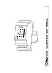
DMA1
D I GI TAL M E S S AGE AN N OU N CER
INS TA LLAT I ON AN D OP E RAT I ON M AN UAL
REMO
T
CONTR E
OL
SD/MM
MEMOR C
Y
VOLUM
ON
PLAY
Digita
2-24
DC IN
E
l Mess
age A
nnoun
DMA1
cer
LOGIC
INP
1 2 3 UTS
4 5 6
7 8
PRE
PRE
IN
OUT
L
R L
R
SPK
OUT
L
R
E
I M P O RTA N T SAF E TY INF ORMATION
1.
Save the carton and packing material even if the equipment has
arrived in good condition. Should you ever need to ship the unit, use
only the original factory packing.
2.
Read all documentation before operating your equipment. Retain
all documentation for future reference.
3.
Follow all instructions printed on unit chassis for proper operation.
4.
Do not spill water or other liquids into or on the unit, or operate
the unit while standing in liquid.
5.
Make sure power outlets conform to the power requirements listed
on the back of the unit.
6.
Do not use the unit if the electrical power cord is frayed or broken.
The power supply cords should be routed so that they are not likely
to be walked on or pinched by items placed upon or against them,
paying particular attention to cords and plugs, convenience
receptacles, and the point where they exit from the appliance.
7.
8.
Always operate the unit with the AC ground wire connected to the
electrical system ground. Precautions should be taken so that the
means of grounding of a piece of equipment is not defeated.
13. Do not block fan intake or exhaust ports. Do not operate equipment
on a surface or in an environment which may impede the normal flow
of air around the unit, such as a bed, rug, weathersheet, carpet,
or completely enclosed rack. If the unit is used in an extremely dusty
or smoky environment, the unit should be periodically “blown free”
of foreign matter.
14. Do not remove the cover. Removing the cover will expose you
to potentially dangerous voltages. There are no user serviceable
parts inside.
15. Do not drive the inputs with a signal level greater than that required
to drive equipment to full output.
16. Do not connect the inputs / outputs of amplifiers or consoles to any
other voltage source, such as a battery, mains source, or power supply,
regardless of whether the amplifier or console is turned on or off.
17. Do not run the output of any amplifier channel back into another
channel’s input. Do not parallel- or series-connect an amplifier output
with any other amplifier output. Australian Monitor Inc is not
responsible for damage to loudspeakers for any reason.
18. Do not ground any red (“hot”) terminal. Never connect a “hot” (red)
output to ground or to another “hot” (red) output!
Mains voltage must be correct and the same as that printed on the
rear of the unit. Damage caused by connection to improper AC voltage
is not covered by any warranty.
19. Non-use periods. The power cord of equipment should be unplugged
from the outlet when left unused for a long period of time.
9.
Have gain controls on amplifiers turned down during power-up
to prevent speaker damage if there are high signal levels at the inputs.
20. Service Information Equipment should be serviced by qualified service
personnel when:
10
Power down & disconnect units from mains voltage before making
connections.
A.
The power supply cord or the plug has been damaged.
B.
Objects have fallen, or liquid has been spilled into the equipment
11. Never hold a power switch in the “ON” position if it won’t stay
there itself!
C. The equipment has been exposed to rain
12. Do not use the unit near stoves, heat registers, radiators, or other heat
producing devices.
D. The equipment does not appear to operate normally, or exhibits a marked
change in performance
E. The equipment has been dropped, or the enclosure damaged.
THIS SAFETY INFORMATION IS OF A GENERAL NATURE AND MAY BE SUPERSEDED BY INSTRUCTIONS CONTAINED WITHIN THIS MANUAL
This symbol is intended to alert the user to the presence
of uninsulated “dangerous voltage” within the products
enclosure that may be of sufficient magnitude to constitute
a risk of electric shock to persons.
CAUTION
RISK OF ELECTRIC SHOCK
DO NOT OPEN
CAUTION: TO REDUCE THE RISK OF ELECTRIC SHOCK,
This symbol is intended to alert the user to the presence
of important operational and maintenance (servicing)
instructions in the literature accompanying the appliance.
DO NOT REMOVE COVER (OR BACK),
NO USER SERVICEABLE PARTS INSIDE,
REFER SERVICING TO QUALIFIED SERVICE PERSONAL.
Caution:
WARNING!
TO REDUCE THE RISK OF FIRE OR ELECTRIC HOCK
DO NOT EXPOSE THIS EQUIPMENT TO RAIN OR MOISTURE.
To prevent electric shock do not use this (polarised) plug
with an extension cord, receptacle or other outlet unless
the blades can be fully inserted to prevent blade exposure.
To prevent electric shock, match wide blade of plug to wide
slot, fully insert.
INTRODUCTION AND CONTENTS
1. INTRODUCTION
1.1
1.2
1.3
1.4
1.5
1.6
1.7
4
6.1
6.2
6.3
Introduction
What is MP3?
Encoder
Decoder
Player
Wave
Audio compression in various formats
2. INSTALLATION
2.1
2.2
4.
Contents of the DMA1 kit
Notices
6
Command description
Connection description
Power supply
Logic inputs
IN/OUT 8 - Vlink input/output
Serial RS485 connection
Line level audio input
Line level audio output
Amplified audio output
5.1
5.2
5.3
5.4
7.1
7.2
8.
Introduction to playlist mode operation
What is a playlist file?
Playlist activation by logic inputs - MPLL
(Mode PLayList) parameter
Stop & Play Priority Playlist
Priority Playlist
Stop & Play Standard Playlist
Standard Playlist
Stop & Play Restart Playlist
Restart Playlist
9.
9
15
Introduction to timed operation
The palimpsest file – palin.txt
Mixer function
AVC function – automatic control of the output volume
20
Logic input operating mode
Binary input command codes
SPECIAL FUNCTIONS
8.1
8.2
What is the configuration file?
Content of the configuration file
How it is managed by the DMA1
Preparing the file
Storing files in Flash memory
Audio adjustment parameters
Timing and switchover parameters
Diagram of operating parameters
Input management parameters
Infrared movement sensor management parameters
5. SCHEDULED OPERATION
17
7. OPERATION WITH LOGIC INPUTS
CONFIGURATION FILE
4.1
4.2
4.3
4.4
4.5
4.6
4.7
4.8
4.9
4.10
6.4
6.5
6.6
6.7
6.8
6.9
5
3. DESCRIPTION AND CONNECTIONS
3.1
3.2
3.3
3.4
3.5
3.6
3.7
3.8
3.9
6. PLAYLIST OPERATION
26
Connection of two DMA1s
Amplifier bridging (40W)
RS485 SERIAL COMMUNICATION
9.1
9.2
9.3
9.4
9.5
9.6
9.7
9.8
9.9
9.10
9.11
9.12
9.13
9.14
9.15
9.16
9.17
28
RS485 communication
Serial port communication parameters (config.txt)
Framing error
NAK reply by a DMA1
Transmitting a command from a control system
Basic format of dedicated protocols
Basic set-up of data packets
Control codes
Address (ADD)
Command (CMD)
CheckSum (CHK)
Basic protocol
Basic protocol with CheckSum
Basic protocol with CR and LF
Basic protocol with CheckSum, CR and LF
List of commands
Error codes
10. SPECIFICATIONS
40
10.1 Technical features
10.2 Maintenance and conservation
10.3 Disposal
AUS, EUR, USA
Copyright 9th Feb 2006
Rev A: 1/03/06
A M I S - D M A 1 I N S TA L L AT I O N & O P E R AT I O N M A N U A L
PA G E 3
INTRODUCTION
1.1 Introduction
1.4 Decoder
The Australian Monitor Installation Series DMA-1 digital message
announcer is a compact yet highly featured digital playback device. Utilizing
an SD card digital storage format the DMA1 delivers high quality stereo
audio in an MP3 format. Messages can be played or triggered using the
on-board controls, via remote switches, contact closure or via RS485 serial
control. The DMA-1 also boasts an on board 20 watt per channel D class
power amplifier as well as stereo inputs & outputs which allow it to be
inserted in line with another BGM feed.
Software which decompresses an MP3 audio file in order to send it to
a digital-analog converter and reconstruct the original audio signal.
The DMA-1’s compact size belies the wealth of features it offers. It is a
highly innovative & cost effective digital message storage & playback
device that has a host of commercial applications.
High quality audio format (extension .wav), compatible with the tracks of
normal music CD’s. CD quality music utilises a sample rate of 44.1 KHz/sec.
at 16 bit in stereo, but the size of the file is approximately about 10Mb per
minute.
1.5 Player
Hardware and software system able to read MP3 audio files. The DMA1
is able to carry out this function.
1.6 Wave
1.2 What is MP3?
MP3 is an acronym for Mpeg-1 layer 3. This is an audio compression
standard which eliminates sounds which the human ear cannot hear via a
psycho-acoustic algorithm. The purpose of this compression is to reduce the
space taken up by an audio file while still ensuring excellent quality. The
greater the compression, the less the audio quality. The right compromise,
which guarantees a quality comparable to that of a Compact Disc, is 128
Kbps (thousands of bits per second) which represents the most widely used
manner, and reduces the size of an uncompressed file by 10 times.
1.7 Audio compression in various formats
The following graphic shows the space taken up by an uncompressed audio
file of about 5 minutes (.wav) and compressed in MP3 at 128Kbps (MP3).
WAVE
MP3
1.3 Encoder
51.1MB
4.6MB
Software which compresses a CD audio or wave file in MP3. There are
many programmes of this kind, and it is virtually impossible to say which is
the best. Freeware software encoders suitable for various
operating systems can be downloaded from the following internet site:
www.mp3server.4t.com
PA G E 4
A M I S - D M A 1 I N S TA L L AT I O N & O P E R AT I O N M A N U A L
I N S TA L L AT I O N
2.1 Contents of the DMA1 kit
2.2 Notices
1x DMA1 device
1.
The DMA1 has been designed to work only with the following mains
power supply adaptors: 12-15VAC, 12-24VDC.
2.
The device must be serviced only by qualified staff.
3.
In order to prevent the risk of fire or shock do not put objects inside the
device through openings
4.
Disconnect the device from power before cleaning. Clean the device
using a soft, dry cloth. Do not use liquids or sprays which contain
flammable substances.
1x DMA1 user manual
1x 240VAC mains power adaptor
1x 128MB flash memory
A M I S - D M A 1 I N S TA L L AT I O N & O P E R AT I O N M A N U A L
PA G E 5
DESCRIPTION AND CONNECTIONS
3.1 Command description
1
Connector for external connection of memory and command buttons
2
Flash memory slot for Secure Digital or MultiMedia Card
3
Command keys:
= (brief pressure) previous MP3 file / (prolonged pressure) reduce output volume
= STOP
= PLAY
= (brief pressure) next MP3 file / (prolonged pressure) increase output volume
4
Red LED:
5
Green LED:
lit = device is on
lit = MP3 file playing;
blinking = DMA1 in pause/STOP.
IMPORTANT!
•
•
Volume control via the keys is only possible during the playing of an MP3 audio file
Pressing STOP during playing causes the DMA1 to pause, until reactivation with
the PLAY key. This condition is indicated by the blinking green LED
1
2
REMOTE
CONTROL
3
4
SD/MMC
MEMORY
5
VOLUME
ON
PLAY
Digital Message Announcer
DMA1
12-24
VDC IN
E
6
PA G E 6
LOGIC
INPUTS
1 2 3 4 5 6 7 8
7
PRE
PRE
SPK
IN
OUT
OUT
L
R L
R L
R
8
9
10
A M I S - D M A 1 I N S TA L L AT I O N & O P E R AT I O N M A N U A L
DESCRIPTION AND CONNECTIONS
3.2 Connection description
6
VAC/DC
Power input 12-15VAC or 12-24VDC
6
+12VDC
Auxiliary + 12Vdc voltage, available for input
activation or external feed sensors. MAX. 100mA
7
GND
Ground for input activation using external contacts;
auxiliary ground voltage
7
IN1
Multi-function input for activating 1.mp3 file or
1.m3u playlist (direct or bit 0 in binary combination)
8
IN L
Line level audio input (left channel), for connection
of external music sources (SAT, CD, Tuner etc)
to be mixed with DMA1 generated audio
8
GND
Ground signal of line level audio input
8
IN R
Line level audio input (right channel), for
connection of external music sources (SAT, CD,
Tuner etc) to be mixed with DMA1 generated audio
9
OUT L
Line level audio output (left channel)
7
IN2
Multi-function input for activating 2.mp3 file or
.m3u playlist (direct or bit 1 in binary combination)
9
GND
Ground signal of line level audio output
9
OUT R
Line level audio output (right channel)
7
IN3
Multi-function input for activating 4.mp3 file or
3.m3u playlist (direct or bit 2 in binary combination)
10
SPK L
Amplified audio output for speaker (20W),
left channel
7
IN4
Multi-function input for activating 8.mp3 file or
4.m3u playlist (direct or bit 3 in binary combination)
10
GND
Ground signal of amplified audio output
10
7
IN5/485A
Multi-function input for activating 16.mp3 file or
5.m3u playlist (direct or bit 4 in binary combination)
configurable for serial RS485 communication
(see chap. 9)
SPK R
Amplified audio output for speaker (20W),
right channel
7
IN6/485B
Multi-function input for activating 32.mp3 file or
6.m3u playlist (direct or bit 5 in binary combination).
Configurable for serial RS485 communication
(see chap. 9)
7
IN/OUT7
Multi-function input/output for activating 64.mp3
file or 7.m3u playlist (direct or bit 6 in binary
combination)
7
IN/OUT8
Multi-function input/output for activating 128.mp3
file (direct or bit 7 in binary combination)
Configurable for external applications. 0=in standby,
1=in play (+12V). Permits two DMA1s to be
connected in cascade for the synchronised
management of music playlists and commercials
spots (spot announcements) in a scheduled time
frame (connection Vlink, par. 8.1)
A M I S - D M A 1 I N S TA L L AT I O N & O P E R AT I O N M A N U A L
PA G E 7
DESCRIPTION AND CONNECTIONS
3.3 Power supply
3.6 Serial RS485 connection
The DMA1 may operate with the following main power adaptors: 1215VAC, 12-24VDC.
It is recommended to use the mains adaptor supplied with the device. The
red POWER LED lights up when power is present.
The DMA1 can be connected to an RS485 bus that can be controlled by
a Crestron control system, or any other RS485 enabled control system.
To enable RS485 control, (pin IN5/485A and IN6/485B), remove the cover
of the DMA1 and move the relative jumpers (see para. 9.1).
3.4 Logic inputs
3.7 Line level audio input
The DMA1 has eight multi-function logic inputs to control the playing of the
either playlists or individual audio files.
Line level audio input (stereo) allowing the connection of an external music
source (SAT, CD, Tuner, second DMA1 etc) that is mixed with DMA1 generated audio. This functionality allows the mixing of a music source with
scheduled commercials or spot announcements.
The pins are:
1GND
2IN 1
3IN
4IN 3
5IN 4
6IN 5
7IN 6
8IN 7
9IN 8
3.8 Line level audio output
Line level audio output (stereo) on extractable terminal strip.
3.9 Amplified audio output
In order to activate the playing of a file, connect the desired logic input pin
to GND (or the desired logic input pins when operating in binary logic).
3.5 IN/OUT 8 - input/output Vlink
Programmable logic input/output to connect two DMA1s in cascade, for
synchronised management of music playlists with commercials/spots at
scheduled intervals without interruptions.
Vlink: 0 = in standby
1 = in play (+12V)
PA G E 8
Amplified stereo audio output (20W + 20W) for the connection of external
speakers.
Connect external 4/8Ω speakers to the SPK L/GND and SPK R/GND terminal strip.
It is recommended to cable the DMA1 far from power cables. The two
cables that connect the speaker with the DMA1 amplified audio output
terminals can be a potential source of interference.
A M I S - D M A 1 I N S TA L L AT I O N & O P E R AT I O N M A N U A L
C O N F I G U R AT I O N F I L E
4.1 What is the configuration file?
4.3 How it is managed by the DMA1
The DMA1 is a very versatile device which can be adapted to the needs
of the application in which it is used. Different applications may require
adjustment of volume, tone, loudness, communication parameters and timing. The configuration file stored in the main directory of the flash memory,
together with the audio files, makes it possible to programme the various
parameters of the DMA1.
At the time the DMA1 is turned on, or when the flash memory card is inserted, the DMA1 will start to read the main directory of the flash memory.
If the file config.txt is found, the DMA1 will store the configuration parameters into its own internal non-volatile memory. The parameters therefore
stay in the internal memory of the DMA1 even after the device has been
turned off or the flash memory card removed. It is therefore not mandatory for the configuration file to always be present on the flash memory
card. Once all the parameters have been read and stored to the DMA1, the
config.txt file can be deleted.
This file must be assigned the name config.txt (this extension has been used
so it can be modified by any text editor, including PocketPC text editors).
4.2 Content of the configuration file
Each line of the configuration file consists of:
•
Mnemonic code of the parameter to be set. It always consists of
our CAPITAL alphanumeric characters, and must always be at the
beginning of the line. No more than one parameter is permitted on
the same line
•
Separating ‘=’ character. This MUST be inserted just after the
mnemonic code, without any spacing or tab characters
•
The relevant numerical parameter expressed as a decimal, to be
inserted directly after the separation character, without any spacing
or tab characters
Example: LMP3=14
LOUT=14
LLIN=14
LLI2=5
LLOU=10
LTRE=10
LBAS=10
MOMD=0
NOTE: If it is necessary to configure multiple DMA1s with the same
configuration parameters, a single flash memory card with the
appropriate config.txt file can be prepared and sequentially insert
this memory card into all the DMA1s to be configured. The final
flash memory cards to be inserted into each DMA1 now only need
to contain the MP3 audio files.
4.4 Preparing the file
Any ordinary text editor (like Windows Notebook) can be used to create the
config.txt file. The file must be saved as a pure text file (.txt). Should other
programmes be used (e.g. Microsoft Word) be careful to save the document
as “text only”: otherwise control characters would be inserted which would
make it impossible for the DMA1 to interpret the file.
4.5 Storing files in flash memory
The configuration file and all the MP3 audio files can be stored to the flash
memory card via a special USB reader/writer for PC.
A M I S - D M A 1 I N S TA L L AT I O N & O P E R AT I O N M A N U A L
PA G E 9
C O N F I G U R AT I O N F I L E
4.6 Audio adjustment parameters
The DMA1 allows for the following audio adjustments:
•
Independent adjustments of the MP3 file level, line level audio input
volume and general amplified/line level output volume
•
Adjustment of loudness level
•
Separate adjustment of bass and treble tone control
•
Adjusting the level of the background music while delivering
commercials/spot announcements
•
Activation/deactivation of power amplifier muting mode
The following tables show the relation between the value set in the
configuration file and the actual value of the audio parameter.
MNEMONIC
DESCRIPTION
LMP3
MP3 decoder output level (value between 0 and 20 in decimal)
LOUT
Main audio output volume (line level outputs and amplified audio outputs) (value between 0 and 20 in decimal)
LLIN
Line level input volume when no MP3 are playing (value between 0 and 20 in decimal)
LLI2
Line level input volume during the playback of MP3 files (value between 0 and 20 in decimal)
LLOU
Loudness level (value between 0 and 20 in decimal)
LTRE
Treble tone control (value between 0 and 20 in decimal)
LBAS
Bass tone control (value between 0 and 20 in decimal)
MOMD
Power amplifier muting mode (0=OFF/1=ON ).
LMP3 (MP3 DECODER OUTPUT LEVEL)
VALUE 0
1
2
3
LEVEL OFF
2%
5%
9%
4
5
6
14% 20% 26%
7
8
9
10
33%
40%
48%
56%
11
12
66% 77%
13
14
15
16
17
18
19
20
88% 100% 112% 128% 144% 161% 178% 200%
0dB
+6dB
LOUT (MAIN AUDIO OUTPUT VOLUME FOR LINE LEVEL AND AMPLIFIED AUDIO OUTPUTS)
VALUE 0
LEVEL OFF
1
2
3
4
5
6
7
8
9
10
11
12
13
14
15
16
17
18
19
20
-55
dB
-35
dB
-28
dB
-23
dB
-20
dB
-17
dB
-14
dB
-12
dB
-10
dB
-8
dB
-6
dB
-4
dB
-2
dB
0
dB
+2
dB
+4
dB
+6
dB
+8
dB
+10
dB
+12
dB
LLIN (INL/INR VOLUME WHEN NO MP3 IS PLAYING)
VALUE 0
LEVEL OFF
1
2
3
4
5
6
7
8
9
10
11
12
13
14
15
16
17
18
19
20
-55
dB
-35
dB
-28
dB
-23
dB
-20
dB
-17
dB
-14
dB
-12
dB
-10
dB
-8 B
dB
-6
dB
-4
dB
-2
dB
0
dB
+2
dB
+4
dB
+6
dB
+8
dB
+10
dB
+12
dB
LLI2 (INL/INR VOLUME DURING THE PLAYBACK OF MP3 FILES (BACKGROUND MUSIC))
VALUE 0
LEVEL OFF
1
2
3
4
5
6
7
8
9
10
11
12
13
14
15
16
17
18
19
20
-55
dB
-35
dB
-28
dB
-23
dB
-20
dB
-17
dB
-14
dB
-12
dB
-10
dB
-8
dB
-6
dB
-4
dB
-2
dB
0
dB
+2
dB
+4
dB
+6
dB
+8
dB
+10
dB
+12
dB
20
LLOU (LOUDNESS LEVEL)
VALUE 0
1
2
3
4
5
6
7
8
9
10
11
12
13
14
15
16
17
18
19
LEVEL 0
dB
+0,5
dB
+1
dB
+1,5
dB
+2
dB
+2,5
dB
+3
dB
+4
dB
+5
dB
+6
dB
+7
dB
+8
dB
+9
dB
+ 10
dB
+11
dB
+ 12
dB
+ 13
dB
+ 14
dB
+ 15
dB
+ 16 + 17
dB
dB
LTRE (TREBLE TONE CONTROL)
VALUE 0
1
2
3
4
5
6
7
8
9
10
11
12
13
14
15
16
17
18
19
20
LEVEL -12
dB
-10
dB
-8
dB
-7
dB
-6
dB
-5
dB
-4
dB
-3
dB
-2
dB
-1
dB
0
dB
+1
dB
+2
dB
+3
dB
+4
dB
+5
dB
+6
dB
+7
dB
+8B
dB
+10
dB
+12
dB
PA G E 1 0
A M I S - D M A 1 I N S TA L L AT I O N & O P E R AT I O N M A N U A L
C O N F I G U R AT I O N F I L E
LBAS (BASS TONE CONTROL)
VALUE 0
1
2
3
4
5
6
7
8
9
10
11
12
13
14
15
16
17
18
19
20
LEVEL -12
dB
-10
dB
-8
dB
-7
dB
-6
dB
-5
dB
-4
dB
-3
dB
-2
dB
-1
dB
0
dB
+1
dB
+2
dB
+3
dB
+4
dB
+5
dB
+6
dB
+7
dB
+8
dB
+10
dB
+12
dB
MOMD (MODE OUTPUT MUTING DISABLE)
MOMD
1 = Muting Deactivated (Internal Power Amplifier Always Active)
0 = Muting Active (Internal Power Amplifier Is Only Active During The Playing Of The Mp3 Files)
4.7 Timing and switchover parameters
The fade times, reaction time of the automatic output volume control and
the delay time for starting the commercial/spot announcement at the end
of the piece of music, can be modified with the following configuration
parameters.
Example: TFOU=15
TFIN=15
TAVC=3
TADU=15
MNEMONIC
DESCRIPTION OF TIMING PARAMETER
TFOU
Setting the Fade-Out time in 1/10 of one second (value between 1 and 30 in decimal)
TFIN
Setting the Fade-In time in 1/10 of one second (value between 1 and 30 in decimal)
TAVC
Setting the reaction time of the automatic output volume control
TADU
Setting the delay time of the commercial/spot in 1/10 of one second (when two DMA1s are operating in cascade)
(value between 0 and 20 in decimal)
TFOU (FADE OUT TIME): SETTING THE FADE OUT TIME OF THE INL/INR AUDIO INPUT BEFORE PLAYING THE MP3 FILE
VALUE
TIME
1
2...4
1/10
second
5
6...9
½
second
10
11...14
1
second
15
16...19
1,5
seconds
20
21...24
2
seconds
25
26...29
2,5
second
30
3
second
TFIN (FADE IN TIME): SETTING THE FADE IN TIME OF THE INR/INL AUDIO INPUT AFTER PLAYING THE MP3 FILE
VALUE
TIME
1
2...4
1/10
second
5
6...9
½
second
10
11...14
1
second
15
16...19
1,5
seconds
20
21...24
2
seconds
25
26...29
2,5
seconds
30
3
seconds
TAVC: SETTING THE REACTION TIME OF THE AUTOMATIC OUTPUT VOLUME CONTROL
VALUE
TIME
0
1
2
3
4
OFF
2/10
seconds
2
seconds
4
seconds
8
seconds
TADU: SETTING THE DELAY TIME OF THE PLAYING A COMMERCIAL/SPOT IN 1/10 SECOND (TWO DMA1S IN CASCADE)
VALUE
TIME
1
1/10
second
2...4
5
½
second
6...9
10
1
second
11...14
15
16...19
1,5
seconds
A M I S - D M A 1 I N S TA L L AT I O N & O P E R AT I O N M A N U A L
20
2
seconds
21...24
25
2,5
seconds
26...29
30
3
seconds
PA G E 1 1
C O N F I G U R AT I O N F I L E
4.8 Diagram of operating parameters
PA G E 1 2
A M I S - D M A 1 I N S TA L L AT I O N & O P E R AT I O N M A N U A L
C O N F I G U R AT I O N F I L E
4.9 Input management parameters
The playing of MP3 files takes place by activating the logic inputs. The
activation modes are set through the IMOD, TPCM MICP and MIRS parameters inserted in the configuration file.
Example: IMOD=0
TPCM=10
MICP=1
MIRS=0
MNEMONIC
DESCRIPTION OF TIMING PARAMETER
IMOD
Setting the mode of the logic inputs as either active high or active low
TPCM
Setting the persistence time of the input command (time to wait before the DMA1
interprets the input command) expressed in decimals of milliseconds (value between
0 and 255 in decimal).
MICP
Setting Mode Input Continuous Play
MIRS
Setting Mode Input ReStart
IMOD (INPUT MANAGEMENT MODE)
IMOD
0 = active-low input mode; the logic input is active when connected to the ground/GND of the device
1 = active-high input mode; the logic input is active when connected to a positive voltage
between 5 and 12VDC
TPCM (TIME PERSISTENCE INPUT COMMAND MODE)
TPCM
0 = no delay
100= 1 second
1 = 10mSeconds
200= 2 seconds
2 = 20mSeconds
250= 2.5 seconds
MICP (MODE INPUT CONTINUOUS PLAY)
MICP
0 = having terminated the playing of the MP3 file, the DMA1 goes into standby
1 = the requested MP3 file is continuously played until a new input code is entered
MIRS (MODE INPUT RESTART)
MIRS
0=repeated activation or deactivating of the same input code does not influence the
playing of the relevant MP3 file. Only the activation of a different code can stop the playing
of the current MP3 file and activate the playing of a new MP3 file
1=The relevant MP3 file commences playing from the beginning, even if the same MP3 is already in play
A M I S - D M A 1 I N S TA L L AT I O N & O P E R AT I O N M A N U A L
PA G E 1 3
C O N F I G U R AT I O N F I L E
4.10 Infrared movement sensor management parameters
IMPORTANT: the following parameters are enabled exclusively for the IN1 input.
Example: PYDT=1
PYDL=10
TAPL=0
RSPL=3
MNEMONIC
DESCRIPTION
PYDT
Activation of IR sensor on IN1 logic input (0=OFF/1=ON )
PYDL
Delay time between the completion of playing an MP3 file and the next IR sensor activation
(value between 0 and 240 in decimal)
TAPL
Setting of the AUTOPLAY time for playing of a message when the IR sensor is not activated
(value between 0 and 240 in decimal)
RSPL
Delay time between IR sensor movement detection and commencement of MP3 playback
(value between 0 and 20 in decimal)
PYDT (ACTIVATION INFRARED MOVEMENT SENSOR)
1 = IR sensor activated
PYDT
0 = IR sensor deactivated
PYDL (DELAY TIME BETWEEN END OF MP3 PLAYBACK AND IR SENSOR RE-ACTIVATION)
VALUE
0
1
2
3
4
5
10
20
30
60
120
180
240
TIME
IR
1
second
2
seconds
3
seconds
4
seconds
5
seconds
10
seconds
20
seconds
30
seconds
1
minute
2
minutes
3
minutes
4
minutes
TAPL (SETTING AUTOPLAY TIME FOR PLAYING FILES WHEN THE IR SENSOR IS NOT ACTIVATED)
VALUE
TIME
0
1
NOT
10
managed seconds
2
3
4
5
6
12
18
30
60
180
240
20
seconds
30
seconds
40
seconds
50
seconds
1
second
2
seconds
3
seconds
5
minutes
10
minutes
30
minutes
40
minutes
20
21...24
25
26...49
50
RSPL (DELAY TIME BETWEEN IR MOVEMENT DETECTION AND START OF MP3 PLAYBACK)
VALUE
TIME
1
1/10
second
PA G E 1 4
2...4
5
1/2
second
6...9
10
1
second
11...14
15
1,5
seconds
16...19
2
seconds
2,5
seconds
5
seconds
A M I S - D M A 1 I N S TA L L AT I O N & O P E R AT I O N M A N U A L
S C H E D U L E D O P E R AT I O N
NOTE: It is very important to start a new line of text for each event,
and to separate the hours from the minutes using the (:) character.
5.1 Introduction to timed operation
When the flash memory card is inserted, the DMA1 will analyse its “
contents and – depending on the files which are present – will
automatically set the mode of operation.
In the presence of the PALIN.TXT file, the DMA1 plays the sequence of MP3
files in a cyclical emission (one hour cycles) called PALIMPSEST which are
contained in the same PALIN.TXT file.
5.2 The palimpsest file – palin.txt
The DMA1 can manage a list of MP3s to be played according to pre-set
time intervals. This list is a simple text file (palin.txt) which contains a
number of time events along with a sequence of MP3 files to be played for
each specific time event.
On the same line the names of the MP3 audio files to be used (and their
sequence) must be defined (max. 8 characters).
There are three different acceptable formats for separating multiple MP3
filenames for each event
1.
Separating character [Tab] between one MP3 and the next:
E.g.: 00:10 spot01
spot02
spot03
2.
Comma (,) between one MP3 and the next:
E.g.: 00:10,spot01,spot02,spot03
3.
Semicolon (;) between one MP3 and the next:
E.g.: 00:10;spot01;spot02;spot03
There are a few simple rules on how to set the palimpsest; firstly the time
for an event must be defined in minutes. Eg: 00:10
Once the configuration has been completed, the file will appear similar to the following example:
00:00
00:05
00:10
00:15
00:20
00:25
00:30
00:35
00:40
00:45
00:50
00:55
SPOT04
SPOT09
SPOT11
SPOT01
SPOT12
SPOT16
SPOT09
SPOT05
SPOT02
SPOT04
SPOT02
SPOT09
SPOT07
SPOT17
SPOT02
SPOT08
SPOT03
SPOT17
SPOT10
SPOT11
SPOT11
SPOT07
SPOT11
SPOT11
SPOT03
SPOT06
SPOT05
SPOT12
SPOT13
SPOT14
EXAMPLE OF PALIN.TXT FILE WITH
CYCLICAL
EMISSION AT INTERVALS OF 5 MINUTES
OF COMMERCIAL SPOTS
An example of the reading and functioning of a timetable is provided below:
00:05
00:11
SPOT05
SPOT01
SPOT11
SPOT07
SPOT12
SPOT03
In this case the DMA1 remains in standby for 5 minutes from the moment it
is turned on. At the 5th minute the DMA1 fades out the external line level
audio input source in order to play the 00:05 time event, composed of 5
MP3 files.
Once the time event has finished playing Spot05, Spot11, Spot12, Spot13
and Spot14, the DMA1 fades the external line level audio input back in.
Upon reaching the 11th minute the DMA1 fades out the external line level
audio input source and plays the 00:10 time event, composed of
3 MP3 files.
A M I S - D M A 1 I N S TA L L AT I O N & O P E R AT I O N M A N U A L
PA G E 1 5
S C H E D U L E D O P E R AT I O N
IMPORTANT! When using the line level audio inputs, check
the settings of the LLIN, LLI2 and MOMD parameters inserted in the
configuration file (par. 4.6).
Programming limits:
Max. programming time permitted
1 hour (cyclic)
Max. quantity of time events
60 events
Max. quantity of MP3s per time event
8 MP3 files
Max. quantity of MP3s per palimpsest
500 MP3 files
5.3 Mixer function
The DMA1 has an audio input for connection to external music sources,
with a mixer function to mix this source with the files played from flash
memory (see par. 8.3). At the time scheduled for delivering each time event
the DMA1 fades out the external audio source from the level LLIN to the
PA G E 1 6
From 00:00 to 00:59
level LLI2, according to a programmed fade time TFOU. Then the sequence
of MP3 files of the time event are played at LMP3 level, mixed with the
external audio source with level LLI2.
Once the time event has finished, the DMA1 brings the external audio
source back to the level LLIN according to a programmed fade time TFIN.
A M I S - D M A 1 I N S TA L L AT I O N & O P E R AT I O N M A N U A L
P L AY L I S T O P E R AT I O N
6.1 Introduction to playlist mode operation
When the flash memory is inserted, the DMA1 analyses its content to
define its mode of operation based upon the files present:
1.
2.
File: PLAYLIST.TXT plays audio files in sequence according to the
list present in the file
File: 1.M3U, 2.M3U, 3.M3U, 4.M3U, 5.M3U, 6.M3U, 7.M3U plays
audio files in sequence according to the list present, activated
by logic input
IN1 = 1.m3u
IN5 = 5.m3u
IN2 = 2.m3u
IN6 = 6.m3u
IN3 = 3.m3u
IN7 = 7.m3u
IN4 = 4.m3u
During play the four command buttons REW, STOP, PLAY and FWD
are active.
6.2 What is a playlist file?
The DMA1 is able to follow a sequence or list of audio files; this play list is
a simple text file called playlist.txt which can be inserted in the main
directory of the same memory containing the audio files.
6.3 Playlist activation by logic inputs - MPLL (Mode PLayList)
parameter
The seven available playlists activated by the logic inputs, can be played
with different modes depending upon the varying needs.
To choose between the different modes of operation the configuration
parameter MPLL (Mode PLayList) must be defined in the config.txt file.
When the flash memory card is inserted, the DMA1, depending on the
setting of the parameter MPLL in the file config.txt, will switch over to the
relevant mode of operation.
IMPORTANT!
• The names of the 7 playlists are fixed
• The loading times of the Playlists may last even tens of seconds,
during which the DMA1 is not able to play
Follow a few, easy rules to set the sequence:
Example
with
numbers:
1
3
7
9
5
01
005
Example
with
names:
intro
part 1
part 2
monologu
music
part 3
finale
IMPORTANT!
• Rename the MP3 audio files with numbers or names with
8 characters max.
• Do not write in the extension (.mp3)
• Max. 500 MP3 files per playlist
Insert the flash memory card and wait for the DMA1 to read the playlist.
At the end of the reading operation, if the names of the pieces have been
fitted in correctly, the DMA1 will automatically start to play the MP3 files in
the programmed sequence or wait the activation of a logic input.
A M I S - D M A 1 I N S TA L L AT I O N & O P E R AT I O N M A N U A L
PA G E 1 7
C O N F I G U R AT I O N F I L E
6.4 MPLL=10: Stop & Play Priority playlist
Operating mode:
•
Upon activation of a logic input, the first MP3 in the playlist is
played. At the end of the MP3 file the DMA1 goes in standby,
awaiting further logic input activation. Activating the logic input
once again, or if the logic input remains active, the next MP3 file
in the playlist is played
INPUTVALUE
•
Repeated activations or deactivations of the same logic input or
of other inputs does not interrupt the playing of an MP3 file
•
The playlist is looped, as long as the relative logic input
remains activated
RELATIVE PLAYLISTV
NONE
=
STANDBY
IN 1
=
1.M3U
Playlist
1.m3u
IN 2
=
2.M3U
Playlist
2.m3u
IN 3
=
3.M3U
Playlist
3.m3u
IN 4
=
4.M3U
Playlist
4.m3u
IN 5
=
5.M3U
Playlist
5.m3u
IN 6
=
6.M3U
Playlist
6.m3u
IN 7
=
7.M3U
Playlist
7.m3u
IN 8
=
VLINK FUNCTION
NOTE: If several inputs are activated, the lowest playlist is activated. For example, if IN4 and
IN5 are active, the playlist 4.m3u is played.
PA G E 1 8
A M I S - D M A 1 I N S TA L L AT I O N & O P E R AT I O N M A N U A L
P L AY L I S T O P E R AT I O N
6.5 MPLL=11: Priority playlist
Operating mode:
•
Upon activation of a logic input, the MP3 files in the playlist are
played in sequence. At the end of the playlist the DMA1 goes in
standby, awaiting further logic input activation. Activating the logic
input once again, or if the logic input remains active, the MP3 files
in the playlist are played again
•
Repeated activations or deactivations of the same logic input or
of other inputs does not interrupt the playing of an MP3 file
•
The playlist is looped, as long as the relative logic input
remains activated
6.6 MPLL=12: Stop & Play Standard playlist
Operating mode as MPLL=10 except:
6.8 MPLL=14: Stop & Play Restart playlist
Operating mode as MPLL=10 except:
•
•
Repeated activations or deactivations of the same logic input does
not influence the playing of the current MP3 file. Only the activation
of a different logic input stops the current MP3 being played and
activates the first MP3 file in the new playlist.
When the same logic input is reactivated the current MP3 file
is restarted. The activation of a different logic input stops the
current MP3 being played and activates the first MP3 file in the
new playlist.
6.7 MPLL=13: Standard playlist
Operating mode as MPLL=11 except:
6.9 MPLL=15 : Restart playlist
Operating mode as MPLL=11 except:
•
•
Repeated activations or deactivations of the same logic input does
not influence the playing of the current playlist. Only the activation
of a different logic input stops the current MP3 being played and
activates the new playlist.
When the same logic input is reactivated the playlist restarts from
the beginning. The activation of a different logic input stops the
current MP3 being played and activates the new playlist.
A M I S - D M A 1 I N S TA L L AT I O N & O P E R AT I O N M A N U A L
PA G E 1 9
O P E R AT I O N W I T H L O G I C I N P U T S
7.1 Logic input operating mode
7.2 Binary input command codes
The DMA1 can also play individual MP3 audio files with direct selection
from eight logic inputs (par. 3.4). The DMA1 enters this working mode
if there are no PALIN.TXT and PLAYLIST.TXT files present.
Activating the logic inputs in binary combination allows the playing of up
to 255 messages, named according to the audio files as shown in the
following table.
Activation is carried out directly or in binary combination, up to a maximum
of 255 files, using the logic inputs IN1, IN2, IN3, IN4, IN5, IN6, IN7 and IN8.
The play modes are set through the IMOD, TPCM, MICP and MIRS
parameters inserted in the configuration files (par. 4.7).
1 2 3
INPUT
4 5
RELEVANT FILES / MESSAGES
6
O
O
O
O
O
O
1
O
O
O
O
O
7 8
=
File.mp3
O
O
=
Standby
O
O
=
1.mp3
individual activation input IN1
O
1
O
O
O
O
O
O
=
2.mp3
individual activation input IN2
1
1
O
O
O
O
O
O
=
3.mp3
binary combination inputs IN1 + IN2
O
O
1
O
O
O
O
O
=
4.mp3
individual activation input IN3
1
O
1
O
O
O
O
O
=
5.mp3
binary combination inputs IN1 + IN3
O
1
1
O
O
O
O
O
=
6.mp3
binary combination inputs IN2 + IN3
1
1
1
O
O
O
O
O
=
7.mp3
binary combination inputs IN1 + IN2 + IN3
O
O
O
1
O
O
O
O
=
8.mp3
individual activation input IN4
1
O
O
1
O
O
O
O
=
9.mp3
binary combination inputs IN1 + IN4
O
1
O
1
O
O
O
O
=
10.mp3
binary combination inputs IN2 + IN4
1
1
O
1
O
O
O
O
=
11.mp3
binary combination inputs IN1 + IN2 + IN4
O
O
1
1
O
O
O
O
=
12.mp3
binary combination inputs IN3 + IN4
1
O
1
1
O
O
O
O
=
13.mp3
binary combination inputs IN1 + IN3 + IN4
O
1
1
1
O
O
O
O
=
14.mp3
binary combination inputs IN2 + IN3 + IN4
1
1
1
1
O
O
O
O
=
15.mp3
binary combination inputs IN1 + IN2 + IN3 + IN4
O
O
O
O
1
O
O
O
=
16.mp3
individual activation input IN5
1
O
O
O
1
O
O
O
=
17.mp3
O
1
O
O
1
O
O
O
=
18.mp3
1
1
O
O
1
O
O
O
=
19.mp3
O
O
1
O
1
O
O
O
=
20.mp3
1
O
1
O
1
O
O
O
=
21.mp3
O
1
1
O
1
O
O
O
=
22.mp3
23.mp3
1
1
1
O
1
O
O
O
=
O
O
O
1
1
O
O
O
=
24.mp3
1
O
O
1
1
O
O
O
=
25.mp3
PA G E 2 0
A M I S - D M A 1 I N S TA L L AT I O N & O P E R AT I O N M A N U A L
O P E R AT I O N W I T H L O G I C I N P U T S
1 2 3
INPUT
4 5
6
7 8
=
File.mp3
RELEVANT FILES / MESSAGES
O
1
O
1
1
O
O
O
=
26.mp3
1
1
O
1
1
O
O
O
=
27.mp3
O
O
1
1
1
O
O
O
=
28.mp3
1
O
1
1
1
O
O
O
=
29.mp3
O
1
1
1
1
O
O
O
=
30.mp3
1
1
1
1
1
O
O
O
=
31.mp3
O
O
O
O
O
1
O
O
=
32.mp3
1
O
O
O
O
1
O
O
=
33.mp3
O
1
O
O
O
1
O
O
=
34.mp3
1
1
O
O
O
1
O
O
=
35.mp3
O
O
1
O
O
1
O
O
=
36.mp3
1
O
1
O
O
1
O
O
=
37.mp3
38.mp3
O
1
1
O
O
1
O
O
=
1
1
1
O
O
1
O
O
=
39.mp3
O
O
O
1
O
1
O
O
=
40.mp3
1
O
O
1
O
1
O
O
=
41.mp3
O
1
O
1
O
1
O
O
=
42.mp3
1
1
O
1
O
1
O
O
=
43.mp3
O
O
1
1
O
1
O
O
=
44.mp3
1
O
1
1
O
1
O
O
=
45.mp3
O
1
1
1
O
1
O
O
=
46.mp3
1
1
1
1
O
1
O
O
=
47.mp3
O
O
O
O
1
1
O
O
=
48.mp3
1
O
O
O
1
1
O
O
=
49.mp3
50.mp3
O
1
O
O
1
1
O
O
=
1
1
O
O
1
1
O
O
=
51.mp3
O
O
1
O
1
1
O
O
=
52.mp3
1
O
1
O
1
1
O
O
=
53.mp3
O
1
1
O
1
1
O
O
=
54.mp3
1
1
1
O
1
1
O
O
=
55.mp3
O
O
O
1
1
1
O
O
=
56.mp3
1
O
O
1
1
1
O
O
=
57.mp3
O
1
O
1
1
1
O
O
=
58.mp3
1
1
O
1
1
1
O
O
=
59.mp3
O
O
1
1
1
1
O
O
=
60.mp3
1
O
1
1
1
1
O
O
=
61.mp3
62.mp3
O
1
1
1
1
1
O
O
=
1
1
1
1
1
1
O
O
=
63.mp3
O
O
O
O
O
O
1
O
=
64.mp3
1
O
O
O
O
O
1
O
=
65.mp3
O
1
O
O
O
O
1
O
=
66.mp3
1
1
O
O
O
O
1
O
=
67.mp3
O
O
1
O
O
O
1
O
=
68.mp3
1
O
1
O
O
O
1
O
=
69.mp3
O
1
1
O
O
O
1
O
=
70.mp3
1
1
1
O
O
O
1
O
=
71.mp3
individual activation input IN6
individual activation input IN7
A M I S - D M A 1 I N S TA L L AT I O N & O P E R AT I O N M A N U A L
PA G E 2 1
O P E R AT I O N W I T H L O G I C I N P U T S
1 2 3
INPUT
4 5
6
7 8
=
File.mp3
RELEVANT FILES / MESSAGES
O
O
O
1
O
O
1
O
=
72.mp3
1
O
O
1
O
O
1
O
=
73.mp3
O
1
O
1
O
O
1
O
=
74.mp3
1
1
O
1
O
O
1
O
=
75.mp3
O
O
1
1
O
O
1
O
=
76.mp3
1
O
1
1
O
O
1
O
=
77.mp3
O
1
1
1
O
O
1
O
=
78.mp3
1
1
1
1
O
O
1
O
=
79.mp3
O
O
O
O
1
O
1
O
=
80.mp3
1
O
O
O
1
O
1
O
=
81.mp3
O
1
O
O
1
O
1
O
=
82.mp3
1
1
O
O
1
O
1
O
=
83.mp3
84.mp3
O
O
1
O
1
O
1
O
=
1
O
1
O
1
O
1
O
=
85.mp3
O
1
1
O
1
O
1
O
=
86.mp3
1
1
1
O
1
O
1
O
=
87.mp3
O
O
O
1
1
O
1
O
=
88.mp3
1
O
O
1
1
O
1
O
=
89.mp3
O
1
O
1
1
O
1
O
=
90.mp3
1
1
O
1
1
O
1
O
=
91.mp3
O
O
1
1
1
O
1
O
=
92.mp3
1
O
1
1
1
O
1
O
=
93.mp3
O
1
1
1
1
O
1
O
=
94.mp3
1
1
1
1
1
O
1
O
=
95.mp3
96.mp3
O
O
O
O
O
1
1
O
=
1
O
O
O
O
1
1
O
=
97.mp3
O
1
O
O
O
1
1
O
=
98.mp3
1
1
O
O
O
1
1
O
=
99.mp3
O
O
1
O
O
1
1
O
=
100.mp3
1
O
1
O
O
1
1
O
=
101.mp3
O
1
1
O
O
1
1
O
=
102.mp3
1
1
1
O
O
1
1
O
=
103.mp3
O
O
O
1
O
1
1
O
=
104.mp3
1
O
O
1
O
1
1
O
=
105.mp3
O
1
O
1
O
1
1
O
=
106.mp3
1
1
O
1
O
1
1
O
=
107.mp3
108.mp3
O
O
1
1
O
1
1
O
=
1
O
1
1
O
1
1
O
=
109.mp3
O
1
1
1
O
1
1
O
=
110.mp3
1
1
1
1
O
1
1
O
=
111.mp3
O
O
O
O
1
1
1
O
=
112.mp3
1
O
O
O
1
1
1
O
=
113.mp3
O
1
O
O
1
1
1
O
=
114.mp3
1
1
O
O
1
1
1
O
=
115.mp3
O
O
1
O
1
1
1
O
=
116.mp3
1
O
1
O
1
1
1
O
=
117.mp3
PA G E 2 2
A M I S - D M A 1 I N S TA L L AT I O N & O P E R AT I O N M A N U A L
O P E R AT I O N W I T H L O G I C I N P U T S
1 2 3
INPUT
4 5
6
7 8
=
RELEVANT FILES / MESSAGES
O
1
1
O
1
1
1
O
=
118.mp3
1
1
1
O
1
1
1
O
=
119.mp3
O
O
O
1
1
1
1
O
=
120.mp3
1
O
O
1
1
1
1
O
=
121.mp3
O
1
O
1
1
1
1
O
=
122.mp3
File.mp3
1
1
O
1
1
1
1
O
=
123.mp3
O
O
1
1
1
1
1
O
=
124.mp3
1
O
1
1
1
1
1
O
=
125.mp3
O
1
1
1
1
1
1
O
=
126.mp3
1
1
1
1
1
1
1
O
=
127.mp3
O
O
O
O
O
O
O
1
=
128.mp3
1
O
O
O
O
O
O
1
=
129.mp3
O
1
O
O
O
O
O
1
=
130.mp3
1
1
O
O
O
O
O
1
=
131.mp3
O
O
1
O
O
O
O
1
=
132.mp3
1
O
1
O
O
O
O
1
=
133.mp3
O
1
1
O
O
O
O
1
=
134.mp3
1
1
1
O
O
O
O
1
=
135.mp3
O
O
O
1
O
O
O
1
=
136.mp3
1
O
O
1
O
O
O
1
=
137.mp3
O
1
O
1
O
O
O
1
=
138.mp3
1
1
O
1
O
O
O
1
=
139.mp3
O
O
1
1
O
O
O
1
=
140.mp3
1
O
1
1
O
O
O
1
=
141.mp3
142.mp3
O
1
1
1
O
O
O
1
=
1
1
1
1
O
O
O
1
=
143.mp3
O
O
O
O
1
O
O
1
=
144.mp3
1
O
O
O
1
O
O
1
=
145.mp3
O
1
O
O
1
O
O
1
=
146.mp3
1
1
O
O
1
O
O
1
=
147.mp3
O
O
1
O
1
O
O
1
=
148.mp3
1
O
1
O
1
O
O
1
=
149.mp3
O
1
1
O
1
O
O
1
=
150.mp3
1
1
1
O
1
O
O
1
=
151.mp3
O
O
O
1
1
O
O
1
=
152.mp3
1
O
O
1
1
O
O
1
=
153.mp3
154.mp3
O
1
O
1
1
O
O
1
=
1
1
O
1
1
O
O
1
=
155.mp3
O
O
1
1
1
O
O
1
=
156.mp3
1
O
1
1
1
O
O
1
=
157.mp3
O
1
1
1
1
O
O
1
=
158.mp3
1
1
1
1
1
O
O
1
=
159.mp3
O
O
O
O
O
1
O
1
=
160.mp3
1
O
O
O
O
1
O
1
=
161.mp3
O
1
O
O
O
1
O
1
=
162.mp3
1
1
O
O
O
1
O
1
=
163.mp3
individual activation input IN8
A M I S - D M A 1 I N S TA L L AT I O N & O P E R AT I O N M A N U A L
PA G E 2 3
O P E R AT I O N W I T H L O G I C I N P U T S
1 2 3
INPUT
4 5
6
7 8
=
RELEVANT FILES / MESSAGES
O
O
1
O
O
1
O
1
=
164.mp3
1
O
1
O
O
1
O
1
=
165.mp3
O
1
1
O
O
1
O
1
=
166.mp3
File.mp3
1
1
1
O
O
1
O
1
=
167.mp3
O
O
O
1
O
1
O
1
=
168.mp3
1
O
O
1
O
1
O
1
=
169.mp3
O
1
O
1
O
1
O
1
=
170.mp3
1
1
O
1
O
1
O
1
=
171.mp3
O
O
1
1
O
1
O
1
=
172.mp3
1
O
1
1
O
1
O
1
=
173.mp3
O
1
1
1
O
1
O
1
=
174.mp3
1
1
1
1
O
1
O
1
=
175.mp3
176.mp3
O
O
O
O
1
1
O
1
=
1
O
O
O
1
1
O
1
=
177.mp3
O
1
O
O
1
1
O
1
=
178.mp3
1
1
O
O
1
1
O
1
=
179.mp3
O
O
1
O
1
1
O
1
=
180.mp3
1
O
1
O
1
1
O
1
=
181.mp3
O
1
1
O
1
1
O
1
=
182.mp3
1
1
1
O
1
1
O
1
=
183.mp3
O
O
O
1
1
1
O
1
=
184.mp3
1
O
O
1
1
1
O
1
=
185.mp3
O
1
O
1
1
1
O
1
=
186.mp3
1
1
O
1
1
1
O
1
=
187.mp3
188.mp3
O
O
1
1
1
1
O
1
=
1
O
1
1
1
1
O
1
=
189.mp3
O
1
1
1
1
1
O
1
=
190.mp3
1
1
1
1
1
1
O
1
=
191.mp3
O
O
O
O
O
O
1
1
=
192.mp3
1
O
O
O
O
O
1
1
=
193.mp3
O
1
O
O
O
O
1
1
=
194.mp3
1
1
O
O
O
O
1
1
=
195.mp3
O
O
1
O
O
O
1
1
=
196.mp3
1
O
1
O
O
O
1
1
=
197.mp3
O
1
1
O
O
O
1
1
=
198.mp3
1
1
1
O
O
O
1
1
=
199.mp3
200.mp3
O
O
O
1
O
O
1
1
=
1
O
O
1
O
O
1
1
=
201.mp3
O
1
O
1
O
O
1
1
=
202.mp3
1
1
O
1
O
O
1
1
=
203.mp3
O
O
1
1
O
O
1
1
=
204.mp3
1
O
1
1
O
O
1
1
=
205.mp3
O
1
1
1
O
O
1
1
=
206.mp3
1
1
1
1
O
O
1
1
=
207.mp3
O
O
O
O
1
O
1
1
=
208.mp3
1
O
O
O
1
O
1
1
=
209.mp3
PA G E 2 4
A M I S - D M A 1 I N S TA L L AT I O N & O P E R AT I O N M A N U A L
O P E R AT I O N W I T H L O G I C I N P U T S
1 2 3
INPUT
4 5
6
7 8
=
RELEVANT FILES / MESSAGES
O
1
O
O
1
O
1
1
=
210.mp3
1
1
O
O
1
O
1
1
=
211.mp3
O
O
1
O
1
O
1
1
=
212.mp3
1
O
1
O
1
O
1
1
=
213.mp3
O
1
1
O
1
O
1
1
=
214.mp3
File.mp3
1
1
1
O
1
O
1
1
=
215.mp3
O
O
O
1
1
O
1
1
=
216.mp3
1
O
O
1
1
O
1
1
=
217.mp3
O
1
O
1
1
O
1
1
=
218.mp3
1
1
O
1
1
O
1
1
=
219.mp3
O
O
1
1
1
O
1
1
=
220.mp3
1
O
1
1
1
O
1
1
=
221.mp3
222.mp3
O
1
1
1
1
O
1
1
=
1
1
1
1
1
O
1
1
=
223.mp3
O
O
O
O
O
1
1
1
=
224.mp3
1
O
O
O
O
1
1
1
=
225.mp3
O
1
O
O
O
1
1
1
=
226.mp3
1
1
O
O
O
1
1
1
=
227.mp3
O
O
1
O
O
1
1
1
=
228.mp3
1
O
1
O
O
1
1
1
=
229.mp3
O
1
1
O
O
1
1
1
=
230.mp3
1
1
1
O
O
1
1
1
=
231.mp3
O
O
O
1
O
1
1
1
=
232.mp3
1
O
O
1
O
1
1
1
=
233.mp3
234.mp3
O
1
O
1
O
1
1
1
=
1
1
O
1
O
1
1
1
=
235.mp3
O
O
1
1
O
1
1
1
=
236.mp3
1
O
1
1
O
1
1
1
=
237.mp3
O
1
1
1
O
1
1
1
=
238.mp3
1
1
1
1
O
1
1
1
=
239.mp3
O
O
O
O
1
1
1
1
=
240.mp3
1
O
O
O
1
1
1
1
=
241.mp3
O
1
O
O
1
1
1
1
=
242.mp3
1
1
O
O
1
1
1
1
=
243.mp3
O
O
1
O
1
1
1
1
=
244.mp3
1
O
1
O
1
1
1
1
=
245.mp3
246.mp3
O
1
1
O
1
1
1
1
=
1
1
1
O
1
1
1
1
=
247.mp3
O
O
O
1
1
1
1
1
=
248.mp3
1
O
O
1
1
1
1
1
=
249.mp3
O
1
O
1
1
1
1
1
=
250.mp3
1
1
O
1
1
1
1
1
=
251.mp3
O
O
1
1
1
1
1
1
=
252.mp3
1
O
1
1
1
1
1
1
=
253.mp3
O
1
1
1
1
1
1
1
=
254.mp3
1
1
1
1
1
1
1
1
=
255.mp3
A M I S - D M A 1 I N S TA L L AT I O N & O P E R AT I O N M A N U A L
PA G E 2 5
SPECIAL FUNCTIONS
8.1 Connection of two DMA1s
Connecting two DMA1s in cascade via the Vlink connection and the audio
inputs/outputs (see figure), can recreate the typical operating mode
of a commercial radio station.
DMA1 with playlist
REMOTE
CONTROL
One DMA1 must be programmed to run in playlist mode, playing the musical
items (PLAYLISTS.TXT), the other DMA1 is programmed to run according to
a schedule (PALIN.TXT) playing the commercials/spot announcements.
DMA1 with palimpsest
SD/MMC
MEMORY
REMOTE
CONTROL
VOLUME
ON
SD/MMC
MEMORY
VOLUME
ON
PLAY
PLAY
Digital Message Announcer
DMA1
12-24
VDC IN
E
LOGIC
INPUTS
1 2 3 4 5 6 7 8
PRE
IN
L
Digital Message Announcer
DMA1
PRE
SPK
OUT
OUT
R L
R L
R
12-24
VDC IN
E
LOGIC
INPUTS
1 2 3 4 5 6 7 8
PRE
IN
L
PRE
SPK
OUT
OUT
R L
R L
R
AMP
PRE
When a time event is to be played the schedule-programmed DMA1 waits
for consent (the completion of playing the current MP3 music file) from
playlist-programmed DMA1, (which goes into standby), before starting to
play the commercials/spot announcements.
PA G E 2 6
Once the playing of the time event is over, the playlist-programmed DMA1
will start to play the following MP3 music file in the playlist.
A M I S - D M A 1 I N S TA L L AT I O N & O P E R AT I O N M A N U A L
SPECIAL FUNCTIONS
8.2 Amplifier Bridging (40W)
The DMA1 has the capability of bridging the outputs of the stereo power
amplifier to create a 40W bridge-mono configuration - to power a single
8ohm loudspeaker of greater power capacity.
To enable this operational mode, in addition to wiring the speaker
in a bridged configuration, it is necessary to set the following parameters
in the config.txt file:
OMON=1
INVR=1
OMON STEREO / MONO AUDIO OUTPUT SWITCH
0= STEREO audio output
1= MONO audio output
OMON
INVR INVERTED RIGHT CHANNEL AUDIO OUTPUT SWITCH
0= right audio output channel not inverted (STEREO)
1= right audio output channel inverted (BRIDGE-MONO configuration)
INVR
Panelplayer 20W + 20W STEREO
REMOTE
CONTROL
Panelplayer 40W MONO
SD/MMC
MEMORY
REMOTE
CONTROL
VOLUME
ON
SD/MMC
MEMORY
VOLUME
ON
PLAY
PLAY
Digital Message Announcer
DMA1
12-24
VDC IN
E
LOGIC
INPUTS
1 2 3 4 5 6 7 8
PRE
IN
L
12-24
VDC IN
E
20W
A M I S - D M A 1 I N S TA L L AT I O N & O P E R AT I O N M A N U A L
PRE
IN
L
–
+
LOGIC
INPUTS
1 2 3 4 5 6 7 8
–
20W
PRE
SPK
OUT
OUT
R L
R L
R
–
+
Digital Message Announcer
DMA1
PRE
SPK
OUT
OUT
R L
R L
R
+
40W
PA G E 2 7
S E R I A L R S 4 8 5 C O M U N I C AT I O N
9.1 RS485 communication
IMPORTANT!
The DMA1 can be connected to a Crestron control system or similar via
RS485 serial connection.
• The internal electronics of DMA1 are not galvanically insulated
from the RS485 line; in case of short circuit or discharge to ground, it
is possible to damage not only the DMA1, but the control system to
which it is connected!
Interference effects and induced noise on the serial line may cause anomalous behaviour and possible damage to the DMA1 unit. To avoid this, take
the following precautions:
1. Do not let the serial cables transit the same conduits as power
cables or cables with elevated voltage. Maintain a safe distance of
at least 10 cm. between these cables
2. Connect the serial cable screen to the ground of one of the
RS485 devices (do not connect the screen at both ends)
3. Disconnect power from the DMA1 and control system before
wiring the serial control lines
The DMA1 supports up to 4 different RS485 modes of operation, according to the RS485 electrical standard. This serial multipoint communication
supports the connection of up to 32 devices, with a maximum bus distance
of 50 metres.
The DMA1 devices connected to the RS485 bus can not autonomously begin
communication, but can respond to a specific request (command) from a
control system.
• The control system must remember to ignore the transmission
echo from the control system that is returned through the RS485
serial line.
IMPORTANT!
• To enable the serial port through the IN5/485A and IN6/485B
pins, remove the cover of the device and move the P1 and P2
jumpers, as indicated in the following figure.
• With an RS485 connection termination resistors must be applied
on both extremes of the serial line to avoid the generation of
stationary waves and to define the impedance of the serial
line - even in absence of serial communications. The DMA1 features
internal termination resistors, enabled through a JP1 bridge jumper.
To deactivate the terminating resistors, remove the cover of the
device and remove the JP1 jumper indicated in the following figure.
The RS485 connection parameters (speed, parity, check-sum, etc.) are set in
the configuration file config.txt. (par. 9.2).
PA G E 2 8
A M I S - D M A 1 I N S TA L L AT I O N & O P E R AT I O N M A N U A L
S E R I A L R S 4 8 5 C O M U N I C AT I O N
Position P1 and P2 jumpers: IN5 and IN6 inputs with logic
operation. (Default
Position P1 and P2 jumpers: IN5 and IN 6 inputs enabled to the
operation as RS485 serial port. To move the bridges, remove
the cover of the device and move the jumpers of the board as
indicated in the figure
A M I S - D M A 1 I N S TA L L AT I O N & O P E R AT I O N M A N U A L
PA G E 2 9
S E R I A L R S 4 8 5 C O M U N I C AT I O N
9.2 Serial port communication parameters (config.txt)
IMPORTANT! notes for the control system
The parameters of the RS485 serial port (length of the packets, parity, speed,
etc.) are set in the configuration file config.txt.
The DMA1 is ready for serial communication instructions under the
following conditions:
These parameters must be compatible with the external control system to
which DMA1 is connected.
• When DMA1 is turned on
• When the previous communication instruction has been
completed
• When the timeout time for the last received/transmitted packet
has expired
IMPORTANT!
To make changes to the communication parameters active, it is
necessary to power-cycle the DMA1 after having inserting a flash
memory card with the updated config.txt file.
The following table lists the values and parameters needed to connect the DMA1 to a control system (protocol, speed, timings, etc.).
MNEMONIC
DESCRIPTION
CMAD
DMA1 address in the RS485 bus (ADD) (Value between 0 and 31 in decimal). IMPORTANT! This address MUST
be unique; two devices with the same address can not co-exist on the same bus.
CMCK
Enabling of Checksum:
0=Checksum deactivated
1=Checksum activated
CMCL
Enabling inclusion of end-of-packet characters CR and LF (hexadecimal values OD and 0A)
0=No CR and LF
1=Insertion of CR and LF active
CMBR
Baud rate (communication speed in bits per second)
0=1200 bps
1=2400 bps
2=4800 bps
3=9600 bps
CMPR
Parity Bits:
0=no parity
1=odd parity
2=even parity
CMSB
Number of Stop Bits
1=1 StopBit
2=2 StopBits
CMDB
Number of data bits
7=7 bits per datum
8=8 bits per datum
CMDR
Minimum delay between end of reception a packet and delivery of the reply.
(Value expressed in tens of 1msec between 0 and 15 in decimal)
0=Minimum delay of 4msec
1=Minimum delay of 10msec
2=Minimum delay of 20msec
PA G E 3 0
A M I S - D M A 1 I N S TA L L AT I O N & O P E R AT I O N M A N U A L
S E R I A L R S 4 8 5 C O M U N I C AT I O N
Reply wait time (CMDR)
9.6 Basic format of dedicated protocols
This is the delay time before the transmission of a reply message, required
by some control systems to switch between the state of transmission and
the state of reception.
The reply waiting time determines the minimum delay before the DMA1
sends data in reply to the message received from the control system. Set
this time at a value different from 0 only if the control system requires it,
since the delay determines an extension of the time needed to complete the
command.
The DMA1 supports up to four dedicated RS485 protocols.
Which of these four protocols is used by the serial connection is defined in
the configuration file config.txt (par. 9.2).
The difference between these four formats is due to the presence or absence
of CheckSum and/or of the end-0f-packet characters CR (Carriage Return,
character 0DH) and LF (Line Feed, character 0AH).
9.3 “ Framing” error
9.7 Basic set-up of data packets
A framing error may take place if nothing is being transmitted on the
serial line.
In order to avoid this mishap, it is recommended that the control system
ignores all data until it has received one of the STX, ACK or NAK characters
coming from a DMA1.
Control code
DMA1 address
9.4 NAK reply by a DMA1
Command code
The reply with the NAK character is sent from DMA1 to the control system
when any kind of error is detected in the received message.
Command data
9.5 Transmitting a command from a control system
When sending a command from the control system to a DMA1, make sure
it is sent after a minimum delay of 10ms after receiving the last instruction
from the DMA1 to ensure the DMA1 has had sufficient time to process the
last request.
CheckSum
CR/LF control codes
IMPORTANT!
When using an RS485 bus remember to ignore the echo of the
command that is sent from the control system (with RS485 an echo
is always present).
A M I S - D M A 1 I N S TA L L AT I O N & O P E R AT I O N M A N U A L
PA G E 3 1
S E R I A L R S 4 8 5 C O M U N I C AT I O N
IMPORTANT!
The introduction of CheckSum at the end of the block of data
and characters of CR + LF is defined in the configuration file
config.txt (par. 9.2).
9.8 Control codes
The control codes are characters (they belong to the first 32 ASCII characters
and cannot be printed out) which define the type of information contained in
the packet following them.
The control codes used are those which appear on the following table.
The DMA1 initialises serial communications when it receives the character
ENQ.
MNEMONIC
CODE
DESCRIPTION
STX
02H
Start TeXt. Beginning of reply packet
ETX
03H
End TeXt. End of reply packet
ENQ
05H
EnQuiry. Beginning of packet addressed to DMA1
ACK
06H
ACKnowledged. Beginning of reply packet: all OK!
LF
0AH
Line Feed. End of line code
CR
0DH
Carriage Return
NAK
15H
Not AcKnowledged. Beginning of reply packet: ERROR!
9.9 Address (ADD)
9.10 Command (CMD)
The address is a unique number that allows the control system to establish
communication with one of the various modules connected to the same serial
communications line.
The DMA1 address is defined in the configuration file config.txt (par. 9.2).
CMD (command) is used to define an operation to be carried out (for example
PLAY, reading the state or setting of the volume). Commands are defined as
ASCII characters and consist of 2 characters.
In the following sections of this chapter a list of commands (and detail about
each command) will be provided.
IMPORTANT!
When setting the address it is necessary to be careful to not define
more than one DMA1 with the same address, otherwise the
communication becomes confused and irregular.
The address can assume any value between 00H and 1FH.
The address is expressed in ASCII characters and consists of
2 characters.
PA G E 3 2
A M I S - D M A 1 I N S TA L L AT I O N & O P E R AT I O N M A N U A L
S E R I A L R S 4 8 5 C O M U N I C AT I O N
9.11 CheckSum (CHK)
CheckSum ensures that packets are complete and not corrupted during
transmission by any noise or interference induced on the RS485 bus.
The CheckSum is calculated summing the hexadecimal values of the ASCII
characters contained in the data packet (excluding the control code). The
two least significant characters (in hexadecimal) of the result represent the
CheckSum value, and are added to the end of the packet (before any CR and
LF characters).
• If CMCK=1, CheckSum will be calculated automatically and added to
the reply packet (any packet beginning ’STX’). When a packet is received,
the DMA1 calculates the CheckSum of the received packet locally and
compares it with the one contained in the packet itself. If the calculated
CheckSum is identical to the received CheckSum the DMA1 perform the
command, otherwise an error packet is transmitted (packet beginning
with ‘NAK’).
• If CMCK=0, CheckSum will not be appended to transmitted packets and
will not be compared (also because it is missing in the data) in the
received packets.
NOTE: CheckSum is enabled by the CMCK parameter of the
configuration file config.txt.
The following figure shows an example of the calculation of a CheckSum in a command packet delivered by the control system
E
ADD
CMD
01
50
DATA
CHK
0132
8C
N
Q
05H 30H
31H 35H
30H
30H 31H
33H
32H
38H
43H
30H + 31H + 35H + 30H + 30H + 31H + 33H + 32H = 18CH
A M I S - D M A 1 I N S TA L L AT I O N & O P E R AT I O N M A N U A L
PA G E 3 3
S E R I A L R S 4 8 5 C O M U N I C AT I O N
9.12 Basic protocol
Reading the data of the DMA1 from the control system
Transmission sequence
E
A
C
N
D
M
Q
D
D
Control System
DMA1
E
A
C
N
D
M
Q
D
D
E
T
D AT A
X
Sending a command to the DMA1 from the Control System
Transmission sequence
E
A
C
N
D
M
Q
D
D
The DATA block
is inserted only
if provided for by
command used
D AT A
Control System
DMA1
PA G E 3 4
E
A
C
N
D
M
Q
D
D
N
A
C
E
A
D
M
R
K
D
D
R
A M I S - D M A 1 I N S TA L L AT I O N & O P E R AT I O N M A N U A L
S E R I A L R S 4 8 5 C O M U N I C AT I O N
9.13 Basic protocol with CheckSum
Reading the data of the DMA1 from the control system
Transmission sequence
*
E
A
C
C
N
D
M
H
Q
D
D
K
Control System
DMA1
S
A
C
T
D
M
X
D
D
D AT A
E
C
T
H
X
K
*
Sending a command to the DMA1 from the Control System
Transmission sequence
E
A
C
N
D
M
Q
D
D
The DATA block
is inserted only
if provided for by
command used
C
D AT A
H
K
Control System
DMA1
*
1.
2.
A
A
C
C
D
M
K
D
D
N
A
C
E
A
D
M
R
K
D
D
R
The CheckSum is introduced if the configuration parameter CMCK=1.
The CheckSum is calculated summing all the characters marked by an asterisk.
A M I S - D M A 1 I N S TA L L AT I O N & O P E R AT I O N M A N U A L
PA G E 3 5
S E R I A L R S 4 8 5 C O M U N I C AT I O N
9.14 Basic protocol with CR and LF
Reading the data of the DMA1 from the control system
Transmission sequence
E
A
C
N
D
M
Q
D
D
C
L
R
F
Control System
DMA1
S
A
C
T
D
M
X
D
D
E
T
D AT A
X
C
L
R
F
*
Sending a command to the DMA1 from the Control System
Transmission sequence
E
A
C
N
D
M
Q
D
D
D AT A
C
L
R
F
The DATA block
is inserted only
if provided for by
command used
Control System
DMA1
PA G E 3 6
A
A
C
C
D
M
K
D
D
N
A
C
E
A
D
M
R
K
D
D
R
C
L
R
F
C
L
R
F
A M I S - D M A 1 I N S TA L L AT I O N & O P E R AT I O N M A N U A L
S E R I A L R S 4 8 5 C O M U N I C AT I O N
9.15 Basic protocol with CheckSum, CR and LF
Reading the data of the DMA1 from the control system
Transmission sequence
*
E
A
C
N
D
M
Q
D
D
C
L
R
F
Control System
DMA1
S
A
C
T
D
M
X
D
D
E
T
D AT A
X
C
L
R
F
*
Sending a command to the DMA1 from the Control System
Transmission sequence
*
E
A
C
N
D
M
Q
D
D
D AT A
C
L
R
F
The DATA block
is inserted only
if provided for by
command used
Control System
DMA1
*
1.
2.
A
A
C
C
D
M
K
D
D
N
A
C
E
A
D
M
R
K
D
D
R
C
L
R
F
C
L
R
F
The CheckSum is introduced if the configuration parameter CMCK=1.
The CheckSum is calculated summing all the characters marked by an asterisk.
A M I S - D M A 1 I N S TA L L AT I O N & O P E R AT I O N M A N U A L
PA G E 3 7
S E R I A L R S 4 8 5 C O M U N I C AT I O N
9.16 List of commands and operating fields
This table provides a list, with the relevant comments, of all the commands
managed by the DMA1.
DESCRIPTION
CMD
COMMAND DATA
REPLY DATA
STATUS request
30
None
abcd
a = State of the player:
S = Stop
P = Play
b = (reserved)
c = (reserved)
d = (reserved)
STOP
31
None
None
PLAY First
32
None
None
PLAY Next
33
None
None
PLAY Prior
34
None
None
PLAY File
50
Name of file without extension
(4 characters only)
None
PLAY File 2
51
Name of file without extension
(4 characters only)
None
SET Volume
52
Level in hexadecimal (0..14H)
None
SET Treble tone control
53
Level in hexadecimal (0..14H)
None
SET Bass tone control
54
Level in hexadecimal (0..14H)
None
SET Loudness
55
Level in hexadecimal (0..14H)
None
Version of firmware
35
None
P = DMA1
x = version
xx = Release Version
State of inputs
37
None
abcdefgh
a = IN/OUT 7
b = IN/OUT 8
c = IN 6
d = IN 5
e = IN 4
f = IN 3
g = IN 2
h = IN 1
Flash memory size
38
None
Size of the flash
(MAX. 4 characters)
Title of item being played
39
None
Title of the item
(MAX. 12 characters)
(automatic STOP before PLAY)
PA G E 3 8
A M I S - D M A 1 I N S TA L L AT I O N & O P E R AT I O N M A N U A L
S E R I A L R S 4 8 5 C O M U N I C AT I O N
9.17 Error codes
The following table lists all the error codes which the DMA1 delivers
together with the NAK packet if problems are found.
CODE
DESCRIPTION
10H
Failure to convert command code (CMD). It could contain characters which are outside the representation
of a hexadecimal value.
The permitted values are: ‘a’ .. ‘f’ ‘A’ …. ‘F’ ‘0’….’9’
11H
Failure to convert the value contained in ‘DATA’ into a number. It could contain characters which are outside
the representation of a hexadecimal value.
The permitted values are: ‘a’ .. ‘f’ ‘A’ …. ‘F’ ‘0’….’9’
12H
Failure to convert the CheckSum (CHK). It could contain characters which are outside the representation
of a hexadecimal value.
The permitted values are: ‘a’ .. ‘f’ ‘A’ …. ‘F’ ‘0’….’9’
13H
CheckSum wrong
14H
Reserved error
20H
Wrong value in the parameter of the command SET_Volume. It could be more than the maximum permitted value
21H
Wrong value in the parameter of the command SET_Treble. It could be more than the maximum permitted value
22H
Wrong value in the parameter of the command SET_Bass. It could be more than the maximum permitted value
23H
Wrong value in the parameter of the command SET_Loudness. It could be more than the maximum permitted value
30H
The command PLAY cannot be processed because the flash memory is missing
31H
The command PLAY (excluding PLAY File 2) cannot be processed because DMA1 is already playing. To solve
the problem, first send the command STOP, or else use the command PLAY_File_2 which automatically stops
any file being played
32H
The file requested via the command PLAY_File or PLAY_File_2 has not been found.
The four characters inserted as an argument for these commands must correspond exactly to the name of the file
intend to play, except for the extension.
E.g.: the command ENQ + 00501234 requires the playing of the file 1234.mp3 on DMA1 with address 00
33H
Failure to play the requested file. The file could be corrupt
A M I S - D M A 1 I N S TA L L AT I O N & O P E R AT I O N M A N U A L
PA G E 3 9
S P E C I F I C AT I O N S
POWER SUPPLY
12-15VAC or 12-24VDC
CONSUMPTION IN STANDBY
1W
PROTECTION
internal fuse, 4A delayed
CAPACITY OF EXTRACTABLE MEMORY
SD/MMC from 32MB to 1GB
INPUT ABSORPTION
5 mA
FORMATS ACCEPTED
MPEG1 layer 3 (file MP3 from 64 to 160 Kbps)
FREQUENCY RESPONSE
20 ~ 20.000 Hz (±3dB)
SIGNAL/NOISE RATIO
> 90dB
HARMONIC DISTORTION
< 0.1%
OUTPUT POWER
AUDIO CONTROLS
20+20W ( 24V / 4 Ω ) THD= 0.04%
- General output volume control
- Control of input volume and background level with mixer function
- Separate bass and treble tone controls
- Loudness level control
- Automatic fade in
- Automatic fade out
CONTROL KEYS
4 buttons REW, PLAY, STOP, FWD and menu functions
CLASSIFICATION
IP30 on the basis of liquid and dust penetration
SIZE
102x102x19mm
10.2 Maintenance and conservation
10.3 Disposal
See par. 2.2
To safeguard the environment, the device and its accessories must be
disposed of according to legal requirements, in properly equipped places or
as special waste.
SERIAL NO. A
If you do not know the legal requirements, please contact the dealer or the
manufacturer.
Product compliant with the safeguard regulations 73/23/EEC, 89/336/EEC and 93/68/EEC about electromagnetic safety and compatibility.
PA G E 4 0
A M I S - D M A 1 I N S TA L L AT I O N & O P E R AT I O N M A N U A L
NOTES
PA G E 4 1
PA G E 4 2
NOTES
PA G E 4 3
AUSTRALIA AND NEW ZEALAND
w w w. a u s t r a l i a n m o n i t o r. c o m . a u
SYDNEY
MELBOURNE
BRISBANE
ADELAIDE
PERTH
AUCKLAND
(NSW & ACT SALES)
(VIC & TAS SALES)
(QLD SALES)
(SA & NT SALES)
(WA SALES)
(NZ SALES)
149 Beaconsfield
Street Silverwater
NSW 2128
Private Bag 149
Silverwater NSW 1811
Phone: (02) 9647 1411
Fax: (02) 9648 3698
Email:
[email protected]
22/277
Middleborough Road
Box Hill VIC 3128
PO Box 151 Blackburn
South VIC 3130
Phone: (03) 9890 7477
Fax: (03) 9890 7977
Email:
[email protected]
42 Commercial Road
Fortitude Valley
QLD 4006
PO Box 871 Fortitude
Valley QLD 4006
Phone: (07) 3852 1312
Fax: (07) 3252 1237
Email:
[email protected]
31 Walsh Street
Thebarton
SA 5031
PO Box 157
Hindmarsh SA 5007
Phone: (08) 8352 4444
Fax: (08) 8352 4488
Email:
[email protected]
299 Fitzgerald Street
West Perth WA 6005
PO Box 404
North Perth
WA 6906
Phone: (08) 9228 4222
Fax: (08) 9228 4233
Email:
[email protected]
Unit B, 11 Piermark
Drive Albany 1331
New Zealand
PO Box 512
Albany 1331
Phone: (09) 415 9426
Fax: (09) 415 9864
Email:
[email protected]
EUROPE / ASIA / MIDDLE EAST
w w w. a u s t r a l i a n m o n i t o r. c o m . a u
INTERNATIONAL SALES
149 Beaconsfield Street Silverwater NSW 2128 Australian
Private Bag 149 Silverwater NSW 1811
Phone: (02) 9647 1411
Fax: (02) 9648 3698
Email: [email protected]