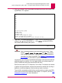
1
AI198
Common Logic Controller
System Manager/User’s Guide
Version 2.2x
Part Number 198UM Rev 2
© 2008 by Kentrox, Inc. All rights reserved.
Copyright © 2008 by Kentrox, Inc. All Rights Reserved. The material discussed in this publication
is the proprietary property of Kentrox, Inc. Kentrox retains all rights to reproduction and
distribution of this publication.
Kentrox is a registered trademark of Kentrox, Inc. Applied Innovation, Applied Innovation Inc., the
AI logo, and other names are the intellectual property of Kentrox. All other product names are
trademarks or registered trademarks of their respective owners.
Information published here is current as of this document’s date of publication, but is subject to
change without notice. You may verify product information by contacting our headquarters in
Oregon. Kentrox is an Equal Opportunity/Affirmative Action employer.
Kentrox, Inc.
5800 Innovation Dr.
Dublin, Ohio USA 43016-3271
Toll Free: (800) 247-9482
International: +1 (614) 798-2000
Fax: +1 (614) 798-1770
20010 NW Tanasbourne Dr.
Hillsboro, Oregon USA 97124-7104
Toll Free: (800) 733-5511
Direct: (503) 643-1681
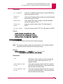
About this Document
This document explains the use and operation of the AI198 common logic controller in an
AIswitch Series 180.
The target audience for this document includes network, maintenance, and technical support
personnel of the AI198. Users of this document are assumed to have working knowledge of:
z
TCP/IP, X.25, and asynchronous data protocols
z
PC or asynchronous terminal configuration
z
Telco networks.
i
AI198 Version 2.2x System Manager/User’s Guide
About this Document: Document Conventions
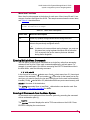
Document Conventions
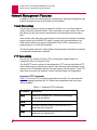
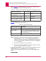
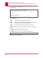
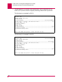
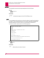
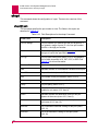
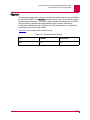
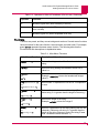
Table 1 describes the text conventions used in this document.
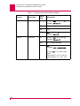
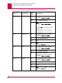
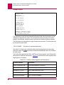
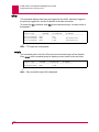
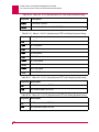
Table 1 Document Conventions
ii
Convention
Meaning
Screen Text, Menu Items,
System Prompts, Messages
and Reports
This style indicates configuration screen text, menu
items, system prompts, messages, and reports.
Commands
Type text that appears in this style exactly as shown.
Variable Command Text
In a command statement, this style indicates text you
specify.
...
In a command statement, ellipses (...) signify that
the preceding parameter can be repeated a number
of times.
[ ]
[ | ]
In a command statement, square brackets indicate
an optional parameter. Two or more parameters in
square brackets with a vertical bar ( | ) between them
indicate a choice of optional parameters.
{ | }
In a command statement, two or more parameters in
braces with a vertical bar ( | ) between them indicate
a choice of required parameters.
Menus and Menu
Commands
This style indicates menu and menu commands. A
vertical bar ( | ) separates the menus from the
submenus or menu commands. The vertical bar also
indicates the order in which you should click the
menus, submenus, and menu commands.
Dialog Boxes, Tabs,
Fields, Check Boxes, and
Command Buttons
This style indicates dialog boxes, tabs, fields, check
boxes, and command buttons.
Variable Field Text
This style indicates variable information you type in a
dialog box field.
KEYS
Uppercase body text indicates keys on a keyboard,
such as the TAB or ENTER keys. Keys used in
combination are connected with a plus symbol (+).
Labels
This style designates physical components on
Kentrox products such as jumper straps, switches,
and cable connectors.
AI198 Version 2.2x System Manager/User’s Guide
About this Document: Document Conventions
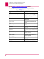
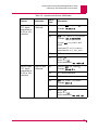
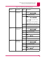
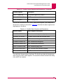
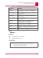
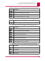
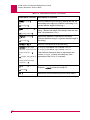
Table 1 Document Conventions (Continued)
Convention
Note:
Important:
Tip:
CAUTION:
WARNING:
LASER DANGER:
Meaning
Note messages provide neutral or positive
information that emphasizes or supplements
important points of the main text.
Important messages provide information that is
essential to the completion of a task.
Tip messages provide information that helps users
use equipment more effectively.
Caution messages indicate that failure to take a
specified action could result in loss of data and/or
harm to the software or hardware.
Warning messages indicate that failure to take a
specified action could result in physical harm to the
user.
Laser danger messages indicate that failure to take a
specified action could result in eye damage or
blindness to the user due to overexposure to invisible
laser radiation.
iii
AI198 Version 2.2x System Manager/User’s Guide
About this Document: Cautions and Warnings
Cautions and Warnings
Battery Warning
WARNING: Danger of explosion if battery is incorrectly replaced. Replace battery
only with the same or equivalent type. Dispose of used batteries
according to the manufacture’s instructions.
Electrostatic Discharge Caution
CAUTION: AI equipment and its peripherals contain electrostatic sensitive
components. Proper handling, shipping, and storage precautions must
be exercised:
z
You must remove and install cards in a static-free environment. Wear
an antistatic wrist strap that is plugged into the AI equipment so you
are grounded at the same point as the equipment.
z
Do not remove cards from their antistatic plastic bags until you are
ready to install them into the chassis.
z
Immediately after you remove a card from the chassis, you must
insert it into its antistatic bag.
z
When the cards are not in use, keep them in their antistatic plastic
bags.
z
Do not ship or store cards near strong electrostatic, electromagnetic,
or radioactive fields.
Ground Caution
CAUTION: For AI equipment to operate safely and correctly, there must be a safety
ground strap between the equipment ground bolts and the office ground.
iv
AI198 Version 2.2x System Manager/User’s Guide
About this Document: Cautions and Warnings
FCC Warning
The Federal Communications Commission has set limits for emitted radio
interference, and AI198 is constructed with this electromagnetic interference (EMI)
limitation in mind. AI198 is classified under FCC regulations as a Class A device, that
is, a device for use in commercial environments and not in residential areas. This
device has been tested and shown to comply with the following FCC rule: Part 15
Subpart J. Operation of this equipment in a residential area may cause interference to
radio and TV reception, requiring the user to take whatever steps are necessary to
correct the interference.
Information is available from the FCC describing possible corrective actions. To
maintain low EMI levels, we suggest that you use only metal connectors and shielded
cable grounded to the frame.
Specifications are subject to change without notice.
v
AI198 Version 2.2x System Manager/User’s Guide
About this Document: Customer Assistance
Customer Assistance
Kentrox offers technical support 24 hours a day, seven days a week.
Before you contact Kentrox for assistance, please have the following information
available:
z
The type of hardware and software you are using
z
The error number and exact wording of any messages that appeared on your
screen
z
What happened and what you were doing when the problem occurred
z
How you tried to solve the problem
Web Site Support
Support is available 24 hours a day using our Web site at:
http://www.kentrox.com
Email Support
Email support is available 24 hours a day. When you use email support, please be
sure to include the details of your problem within the email.
To contact Technical Support, send email to:
[email protected]
Phone Support
Phone support is available. When you call Kentrox for support, please be sure you
are at your computer and have the details of your problem available.
To contact Technical Support, call (866) 480-3571.
Kentrox Product Documentation
To order documentation, please contact your sales representative at
(800) 247-9482 or +1 (614) 798-2000.
You can also access and view the most current versions of Kentrox product
documentation on our Web site at:
http://www.kentrox.com
vi
Table of Contents
Chapter 1: AI198 Overview ....................................................................1-1
Product Description ...................................................................................................... 1-2
Technical Specifications ................................................................................... 1-3
AI198 Functionality ....................................................................................................... 1-4
Menu Driven Configuration ............................................................................... 1-4
Dedicated Asynchronous Craft Port ................................................................. 1-4
Background Connections ................................................................................. 1-4
Activity/Alarm Log ............................................................................................. 1-4
Backplane Alarms ............................................................................................ 1-4
Call Routing ...................................................................................................... 1-5
Autoswitching to Backup CLC .......................................................................... 1-5
Automatic CLC Update ..................................................................................... 1-5
EIA Modem Simulation for Connection ............................................................ 1-5
Network Management Features ................................................................................... 1-6
Telnet Connections .......................................................................................... 1-6
FTP Connectivity .............................................................................................. 1-6
SNMP Manageability ........................................................................................ 1-8
Automatic Reboot ............................................................................................. 1-8
AI2524 Configuration ........................................................................................ 1-8
Firmware Upload/Download to CLC ................................................................. 1-8
Firmware Download to Smart Line Cards ........................................................ 1-9
Configuration Upload/Download ....................................................................... 1-9
Hot-Swap ................................................................................................................... 1-10
AI2524 and AI294 Configuration Storage and Hot-Swap ............................... 1-10
CLC Procedure ............................................................................................... 1-11
Smart Line Card Procedure ............................................................................ 1-11
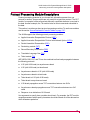
Chapter 2: Quick-Start Configuration .....................................................2-1
Requirements ............................................................................................................... 2-2
Connecting to the Craft Port ......................................................................................... 2-3
CLC Initialization .......................................................................................................... 2-4
Setting for Redundant CLCs ............................................................................ 2-4
Power-Up Sequence for Expander Chassis ..................................................... 2-4
System Reset Message ................................................................................... 2-4
CLC Initialization Sequence ............................................................................. 2-4
Basic Configuration ...................................................................................................... 2-6
TOC-1
Table of Contents
Logging in to AI ................................................................................................ 2-6
Reinitializing Configuration to Factory Defaults ................................................ 2-6
Chapter 3: Introduction to System Configuration ...................................3-1
Terms ........................................................................................................................... 3-2
Ports, Links, Spans and TDSs ......................................................................... 3-2
Destinations ...................................................................................................... 3-2
Aliases .............................................................................................................. 3-2
Configuration Methods ................................................................................................. 3-3
Menu System ................................................................................................... 3-3
config Command .............................................................................................. 3-3
Configuration Via SNMP Manager ................................................................... 3-3
Configuration Upload/Download ....................................................................... 3-3
Data Entry Menu Items ................................................................................................ 3-5
Strings .............................................................................................................. 3-5
Extended Strings .............................................................................................. 3-5
Decimal Numbers ............................................................................................. 3-5
Hexadecimal Numbers ..................................................................................... 3-5
Internet Addresses ........................................................................................... 3-5
Accessing the AI180 .................................................................................................... 3-6
Access Via the Craft Port ................................................................................. 3-6
Access Through Background Connections ...................................................... 3-7
Access Via Telnet ............................................................................................. 3-9
Account Profiles and User Account Security .............................................................. 3-11
Permission Profiles and Default Commands .................................................. 3-11
Setting Up User Accounts .......................................................................................... 3-15
Managing User Accounts ........................................................................................... 3-16
Managing Permission Profiles .................................................................................... 3-17
Chapter 4: System Configuration by Menu ............................................4-1
Starting and Ending a Menu Session ........................................................................... 4-2
Starting a Menu Session .................................................................................. 4-2
Ending a Menu Session ................................................................................... 4-2
Navigating Menus ........................................................................................................ 4-3
Menu Names .................................................................................................... 4-3
Selecting Menu Items ....................................................................................... 4-3
Types of Menu Items ........................................................................................ 4-3
Entering Multiple Menu Commands ................................................................. 4-5
Entering AI Commands from the Menu System ............................................... 4-5
Configuring the AI198 .................................................................................................. 4-7
Menu 1: Configure Options Affecting the System as a Whole ..................................... 4-8
Set Log and Alarm Thresholds ....................................................................... 4-10
TOC-2
Table of Contents
Configuring User Terminals ............................................................................ 4-14
AIswitch Commands Issued upon Restart ..................................................... 4-16
AIswitch Commands Issued After Configuration Restart ............................... 4-18
Display of Destination Names and Automatic CLC Update ........................... 4-20
Network Parameters ....................................................................................... 4-21
Time and Date Format ................................................................................... 4-24
SNMP Trap Table ........................................................................................... 4-26
Configure Banner ........................................................................................... 4-26
SNTP Configuration ....................................................................................... 4-28
Login Security Configuration .......................................................................... 4-29
CLC Trap ........................................................................................................ 4-35
Exiting Menu 1 ................................................................................................ 4-36
Menu 2: Create, Delete, or Modify a Destination Name ............................................. 4-37
Create or Modify a Destination Name ............................................................ 4-37
Delete a Destination Name ............................................................................ 4-42
Menu 3: Display all Destination Names ..................................................................... 4-44
Menu 4: Configure Cards ........................................................................................... 4-46
Menu 5: Set or Remove Connection Restrictions Based on Port Numbers ............... 4-51
Menu 6: Display all Connection Restrictions Based on Port Numbers ...................... 4-53
Menu 7: Configure Slot Density ................................................................................. 4-55
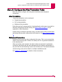
Menu 8: Configure the Alias Translation Table .......................................................... 4-57
Alias Translations ........................................................................................... 4-57
Multiplexed Connections ................................................................................ 4-57
Menu 9: Display the List of Alias Translation Entries ................................................. 4-58
Menu 10: Configuring the BOOTP Table ................................................................... 4-61
Chapter 5: Configuration by SNMP ........................................................5-1
SNMP and AppliedView ............................................................................................... 5-2
SNMP ............................................................................................................... 5-2
AppliedView ...................................................................................................... 5-2
Configuring with SNMP and AppliedView .................................................................... 5-3
Configuring Smart Line Cards .......................................................................... 5-3
Configuring the AI198 ....................................................................................... 5-3
SNMP Trap Table Support for Independent Smart Line Cards ........................ 5-3
Altering Default Community Names using SNMP ............................................ 5-3
SNMP and the AI2524 ................................................................................................. 5-4
Card Table ........................................................................................................ 5-4
Auto ID Table ................................................................................................... 5-4
Link Status Table .............................................................................................. 5-4
SNMP and the AI294 ................................................................................................... 5-5
AI198 MIB .................................................................................................................... 5-6
SNMP Traps ................................................................................................................. 5-7
TOC-3
Table of Contents
SNMP Trap Support for Asynchronous Ports ................................................... 5-7
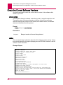
Chapter 6: Downloading Software and Configurations ..........................6-1
Check the Current Software Versions .......................................................................... 6-2
show version .................................................................................................... 6-2
status ................................................................................................................ 6-2
update .............................................................................................................. 6-3
Download the New Software ........................................................................................ 6-4
Asynchronous File Transfer Method ................................................................ 6-5
FTP Method ...................................................................................................... 6-7
Activate a CLC Software Image ................................................................................... 6-9
Active CLC ....................................................................................................... 6-9
Backup CLC ..................................................................................................... 6-9
Resetting the AI180 ........................................................................................ 6-10
Upload Software into a Target Smart Line Card ........................................................ 6-11
winslc update .................................................................................................. 6-11
update/s .......................................................................................................... 6-13
Downloading and Uploading Configurations .............................................................. 6-14
Symbolic Format Using dmpcfg ..................................................................... 6-14
Compressed ASCII Hexadecimal Format Using DMPEE .............................. 6-15
Binary Configuration Image Via FTP .............................................................. 6-16
Chapter 7: Call Routing ..........................................................................7-1
Routing Calls ................................................................................................................ 7-3
Route Calls with Aliases ............................................................................................... 7-4
Address Strings ............................................................................................................ 7-5
Name Matching ............................................................................................................ 7-7
Alias Name Matching Process ..................................................................................... 7-8
Step 1: Determine Search String ...................................................................... 7-8
Step 2: Match Search String to all Destination Names .................................... 7-8
Step 3: Match Alias Names .............................................................................. 7-8
Searching Alias Descriptions ............................................................................ 7-9
Alternate Routing ....................................................................................................... 7-10
Example 1: Call Data Only, Successful Call ................................................... 7-10
Example 2: Call Data and Called Address, Successful Call ........................... 7-10
Example 3: Call Data Only, Failed Call .......................................................... 7-11
Example 4: Call Data and Called Address, Failed Call .................................. 7-12
About Call Capacity on the TDS Bus ............................................................. 7-13
Before You Configure Call Routes ............................................................................. 7-15
Routing Calls on the TDS Bus ................................................................................... 7-16
Simple Alias Translation ............................................................................................. 7-17
Creating a Simple Alias .................................................................................. 7-17
TOC-4
Table of Contents
Multiplexed Connections (MUXs) .............................................................................. 7-19
Creating a Multiplexed Connection (MUX) ..................................................... 7-20
Enabling the Multiplexed Connection ............................................................. 7-21
Aliases That Only Use MUXs ..................................................................................... 7-22
Creating a Multiplexed Only Alias .................................................................. 7-22
Calls Routed on the IRB ............................................................................................. 7-24
Before You Begin ........................................................................................... 7-24
Creating an Alias that uses the IRB ............................................................... 7-25
Source/Destination Protocol Tables ........................................................................... 7-27
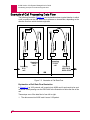
Example of Call Processing Data Flow ...................................................................... 7-38
Protocol Processing Module Descriptions .................................................................. 7-41
AEP ................................................................................................................ 7-42
AEPN .............................................................................................................. 7-43
PAD ................................................................................................................ 7-43
PKT ................................................................................................................ 7-44
RBP ................................................................................................................ 7-46
TL1 ................................................................................................................. 7-47
TN ................................................................................................................... 7-48
Examples of IRB Routing ........................................................................................... 7-50
Using a Single Alias for Routing Calls Between Two SLCs ........................... 7-50
Example of MLT Routing ............................................................................................ 7-56
Menu Descriptions ..................................................................................................... 7-58
Menu 8 ........................................................................................................... 7-58
Menu 8.2 ........................................................................................................ 7-61
Menu 8.14 ...................................................................................................... 7-62
Chapter 8: Commands from the AI Prompt ............................................8-1
Conventions ................................................................................................................. 8-2
Command Prompt ........................................................................................................ 8-3
Editing Command Lines Using Keys ................................................................ 8-3
Alphabetic Command Summary .................................................................................. 8-4
// ................................................................................................................................. 8-12
account ....................................................................................................................... 8-13
account/a ........................................................................................................ 8-13
account/l ......................................................................................................... 8-13
account/d ........................................................................................................ 8-14
accountp ..................................................................................................................... 8-15
accountp/a ...................................................................................................... 8-15
accountp/e ...................................................................................................... 8-16
accountp/d ...................................................................................................... 8-16
accountp/l profile name .................................................................................. 8-17
accountp/l ....................................................................................................... 8-17
accountp/n ...................................................................................................... 8-18
TOC-5
Table of Contents
active .......................................................................................................................... 8-19
alrclr ........................................................................................................................... 8-20
alrset .......................................................................................................................... 8-21
alrsho ......................................................................................................................... 8-22
blast ............................................................................................................................ 8-23
bnc ............................................................................................................................. 8-24
break .......................................................................................................................... 8-25
break port# ..................................................................................................... 8-25
break/b id ........................................................................................................ 8-25
break/s id ........................................................................................................ 8-25
bye ............................................................................................................................. 8-26
cfgmsg ........................................................................................................................ 8-27
cfgmsg n ......................................................................................................... 8-27
cfgmsg n,message ......................................................................................... 8-27
cfgmsg n, ........................................................................................................ 8-28
cfgmsg n,[default] ........................................................................................... 8-28
clcip ............................................................................................................................ 8-29
clist ............................................................................................................................. 8-30
clr ............................................................................................................................... 8-31
clrals ........................................................................................................................... 8-32
clrtrap ......................................................................................................................... 8-33
clsoff ........................................................................................................................... 8-34
clson ........................................................................................................................... 8-35
commstr ..................................................................................................................... 8-36
config .......................................................................................................................... 8-37
cpycnf ......................................................................................................................... 8-38
cpycrd ......................................................................................................................... 8-39
crdump ....................................................................................................................... 8-40
debug ......................................................................................................................... 8-41
debug value .................................................................................................... 8-41
debug/a value ................................................................................................. 8-41
debug/r value .................................................................................................. 8-41
dep ............................................................................................................................. 8-45
dhold .......................................................................................................................... 8-46
disabl .......................................................................................................................... 8-47
dmpcfg ....................................................................................................................... 8-48
dmpee ........................................................................................................................ 8-49
dmpslc ........................................................................................................................ 8-50
dump .......................................................................................................................... 8-51
dwnld .......................................................................................................................... 8-52
eb ............................................................................................................................... 8-53
eb[/p] aaaa ..................................................................................................... 8-53
eb/m ............................................................................................................... 8-53
TOC-6
Table of Contents
eed ............................................................................................................................. 8-54
eed aaaa vv .................................................................................................... 8-54
eed/s msglvl vv ............................................................................................... 8-54
eesize ......................................................................................................................... 8-56
enabl .......................................................................................................................... 8-57
ex ............................................................................................................................... 8-58
fast ............................................................................................................................ 8-59
flush ............................................................................................................................ 8-60
help ............................................................................................................................ 8-61
inv ............................................................................................................................... 8-62
inv/c ............................................................................................................................ 8-63
ioact ............................................................................................................................ 8-64
leds ............................................................................................................................. 8-65
lists ............................................................................................................................. 8-66
lo ................................................................................................................................ 8-67
lock ............................................................................................................................. 8-68
loglvl ........................................................................................................................... 8-69
loglvl ............................................................................................................... 8-69
loglvl craft[,sholog[,caaml]] ............................................................................. 8-69
loglvl/r ............................................................................................................. 8-69
logoff .......................................................................................................................... 8-70
logout ......................................................................................................................... 8-71
loop ............................................................................................................................ 8-72
lstdsb .......................................................................................................................... 8-73
mcon .......................................................................................................................... 8-74
menu .......................................................................................................................... 8-75
menuro ....................................................................................................................... 8-76
netclr .......................................................................................................................... 8-77
netsta ......................................................................................................................... 8-78
password .................................................................................................................... 8-79
password oldpswd newpswd .......................................................................... 8-79
password oldpswd newpswd username ......................................................... 8-79
pick ............................................................................................................................. 8-80
plist ............................................................................................................................. 8-81
prtdsc ......................................................................................................................... 8-82
pstat ................................................................................................................ 8-82
repeat ......................................................................................................................... 8-88
reset ........................................................................................................................... 8-89
restee ......................................................................................................................... 8-90
restee address data [data...] ........................................................................... 8-90
restee/r address count data ............................................................................ 8-90
selcnf .......................................................................................................................... 8-91
TOC-7
Table of Contents
selcnf/b ........................................................................................................... 8-91
selcnf/c ........................................................................................................... 8-91
send ........................................................................................................................... 8-93
shell ............................................................................................................................ 8-94
shobgc ........................................................................................................................ 8-95
shocls ......................................................................................................................... 8-96
sholog ......................................................................................................................... 8-97
shoprt ......................................................................................................................... 8-98
shoprt[/l] port .................................................................................................. 8-98
shoprt[/l]lport-hport ....................................................................................... 8-100
slist ........................................................................................................................... 8-102
stacls ........................................................................................................................ 8-103
staeia ........................................................................................................................ 8-104
staprt ........................................................................................................................ 8-105
staslc ....................................................................................................................... 8-106
stat ........................................................................................................................... 8-107
states ........................................................................................................................ 8-108
status ........................................................................................................................ 8-109
stpslc ........................................................................................................................ 8-110
swcpu ....................................................................................................................... 8-111
telnet ........................................................................................................................ 8-112
telnet xxx.xxx.xxx.xxx ................................................................................... 8-112
telnet xxx.xxx.xxx.xxx [Port#] ....................................................................... 8-113
test ........................................................................................................................... 8-114
tftpstat ...................................................................................................................... 8-115
time .......................................................................................................................... 8-116
tmract ....................................................................................................................... 8-117
tstini .......................................................................................................................... 8-119
unlock ....................................................................................................................... 8-120
update ...................................................................................................................... 8-121
update [sbank dbank] ................................................................................... 8-121
update/c secondary ...................................................................................... 8-123
update/f baseport ......................................................................................... 8-123
update/s ........................................................................................................ 8-123
watcpu ...................................................................................................................... 8-125
who ........................................................................................................................... 8-126
who/a ............................................................................................................ 8-126
winslc ....................................................................................................................... 8-127
wndrct ....................................................................................................................... 8-128
Chapter 9: Messages .............................................................................9-1
Contacting Technical Support ...................................................................................... 9-2
User Input Errors .......................................................................................................... 9-3
TOC-8
Table of Contents
Log Messages ............................................................................................................. 9-4
Severity Levels ................................................................................................. 9-4
Message Text ................................................................................................... 9-5
Normal Activity (Level 0) Messages ............................................................................. 9-6
Transient Call (Level 1) Messages ............................................................................... 9-7
Severe Call Processing (Level 3) Messages ............................................................... 9-9
Link Down (Level 4) Messages .................................................................................. 9-10
Severe Software Error (Level 5) Messages ............................................................... 9-11
Partial Hardware Fault (Level 6) Messages ............................................................... 9-12
Total Hardware (Level 7) Messages .......................................................................... 9-13
User Requested (Level F) Messages ......................................................................... 9-14
Startup Messages ...................................................................................................... 9-15
AI2524 ............................................................................................................ 9-15
AI294 .............................................................................................................. 9-15
SNMP Traps ............................................................................................................... 9-16
Trap Messages ............................................................................................... 9-16
Proprietary MIB Objects Sent with AI198 SNMP Traps ................................. 9-20
Crash Codes .............................................................................................................. 9-23
Common Crash Codes ................................................................................... 9-23
AI198 Crash Codes ........................................................................................ 9-24
Appendix A: ASCII Codes ..................................................................... A-1
Table A-1: ASCII Codes ...............................................................................................A-2
Table A-2: Decimal Values ...........................................................................................A-3
Appendix B: The config Command ....................................................... B-1
Overview ......................................................................................................................B-2
Menu Keywords ................................................................................................B-2
Item Keywords ..................................................................................................B-2
Special Keywords .............................................................................................B-2
Valid Values .....................................................................................................B-3
Delimiters .........................................................................................................B-3
Strings ..............................................................................................................B-3
Menu Items by Number ....................................................................................B-4
Prerequisite Menu Items ..................................................................................B-4
Multiple Menu Items .........................................................................................B-5
Precautions for Configuring a Range of Ports ..................................................B-5
config Commands Associated with Menus ..................................................................B-6
config Commands Not Associated with Menus ..........................................................B-59
config accountp/c ...........................................................................................B-59
config accountp/e ...........................................................................................B-59
TOC-9
Table of Contents
config accountp/s ...........................................................................................B-60
config account/a .............................................................................................B-60
config clcinfo ...................................................................................................B-60
config commnames ........................................................................................B-61
config mibII .....................................................................................................B-62
config trap .......................................................................................................B-63
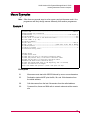
Appendix C: Reading Alias Macros ....................................................... C-1
Overview ......................................................................................................................C-2
Macro Facts ......................................................................................................C-2
The Backslash Character .................................................................................C-2
Parts of a Macro ...........................................................................................................C-3
Start ..................................................................................................................C-3
Comments ........................................................................................................C-3
Constants .........................................................................................................C-4
Variables ..........................................................................................................C-4
MS DOS wildcard symbols ...............................................................................C-5
Operators .........................................................................................................C-5
Functions ..........................................................................................................C-7
Macro Examples ..........................................................................................................C-9
Example 1 ........................................................................................................C-9
Example 2 ......................................................................................................C-10
Example 3 ......................................................................................................C-11
Example 4 ......................................................................................................C-12
Example 5 ......................................................................................................C-13
Appendix D: Menu 4.2: Configure as... ................................................. D-1
Menu 4.2.2: Configure as AI183/185 standard 4/16 port card .....................................D-2
Menu 4.2.2 .......................................................................................................D-2
Menu 4.2.2.2: Port Destination Name ..............................................................D-6
Menu 4.2.2.4: If autobaud is OFF this port operates at ....................................D-7
Menu 4.2.2.5: Port Bits per Character ..............................................................D-8
Menu 4.2.2.6 Port Stop Bits .............................................................................D-8
Menu 4.2.2.7: Port Parity ..................................................................................D-9
Menu 4.2.2.11: Disconnect via Break ...............................................................D-9
Menu 4.2.2.12: EIA Disconnect ......................................................................D-10
Menu 4.2.2.13: EIA Pin State for Idle and Connect ........................................D-12
Menu 4.2.3: Configure as AI193/194 Ethernet card with slot expansion of ...............D-14
Menu 4.2.3.9: Set Ethernet performance parameters ....................................D-17
Menu 4.2.3.13: AI194 Port Descriptions .........................................................D-20
Menu 4.2.4: Configure as AI192/196 X.25 network card with slot expansion of ........D-21
Menu 4.2.4.6: Baud rate is internal at 9600 ...................................................D-25
TOC-10
Table of Contents
Menu 4.2.4.7: CCITT link is (DCE) with active disconnect .............................D-26
Menu 4.2.4.8: Maximum packet size is 128 ...................................................D-27
Menu 4.2.4.9: Frame level modulus is 8 ........................................................D-27
Menu 4.2.4.13: Packet level modulus is 8 ......................................................D-28
Menu 4.2.4.16: Protocol processing is ...........................................................D-28
Menu 4.2.4.17: Set X.25 facilities ...................................................................D-30
Menu 4.2.4.17.13: Line build out -- DSX-1 crossconnect; 133 to 266 feet (40 to 80
meters) ...........................................................................................................D-32
Menu 4.2.5: Configure as ASP or Advanced Smart Line Card with slot expansion of D-33
Menu 4.2.12: Configure as AI192/196 with full menu support ...................................D-35
Menu 4.2.12.6: Baud rate is ...........................................................................D-39
Menu 4.2.12.7: CCITT link is (DCE) with active disconnect ...........................D-39
Menu 4.2.12.9: PVC configuration .................................................................D-40
PVC Edit Menu ...............................................................................................D-42
Menu 4.2.12.10: Frame level information .......................................................D-43
Menu 4.2.12.13: Packet level information ......................................................D-44
Menu 4.2.12.16: Protocol processing is .........................................................D-45
Menu 4.2.12.17: Set X.25 Facilities ................................................................D-47
Menu 4.2.12.17.13: Line build out -- DSX-1 crossconnect; 0 to 133 feet (0 to 40
meters) ...........................................................................................................D-49
TOC-11
Table of Contents
TOC-12
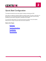
1
AI198 Overview
This chapter provides an overview of the AI198 common logic controller (CLC).
In the AI180, the AI198 CLC is the only card explicitly required. At least one CLC is necessary to
control the chassis. The CLC maintains contact with the smart line cards (SLCs) in the AI180,
directing their interactions with each other and with any outside network components. It is also
the central point for modifying and storing card configurations.
A backup CLC should be installed in the AI180 chassis. If the primary CLC fails, the backup will
take over.
The AI198 can download software for itself and for other smart line cards. This includes Telnet,
FTP, SNMP support, and many other features and commands that will be further discussed in
this chapter.
Guide to this Chapter
Product Description
AI198 Functionality
Network Management Features
Hot-Swap
1-1
AI198 Version 2.2x System Manager/User’s Guide
AI198 Overview: Product Description
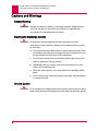
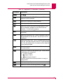
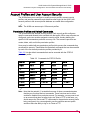
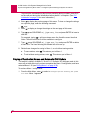
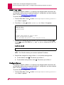
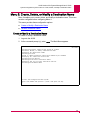
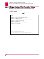
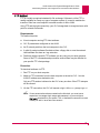
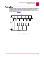
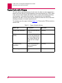
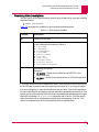
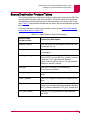
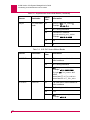
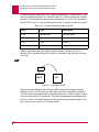
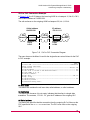
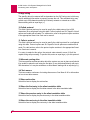
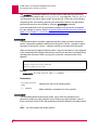
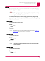
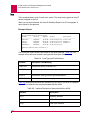
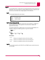
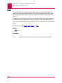
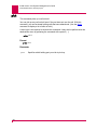
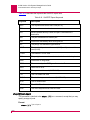
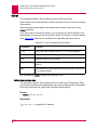
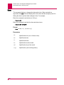
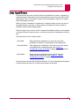
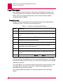
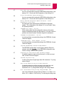
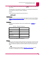
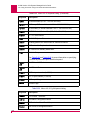
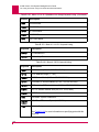
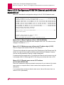
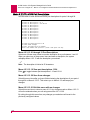
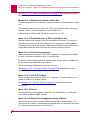
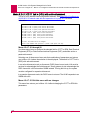
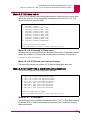
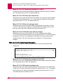
Product Description
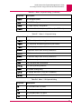
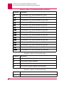
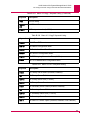
DC OK
DC OK
On when +5 V is present.
FAULT
On if the card fails.
SEL
Identifies which CLC is active. In a
system with redundant CLCs, only one
should be on at any given time.
BOOT
Resets the entire AI180. The AI180 will
restart using its saved configuration
settings. Push this button after a fault
has been corrected to switch back to the
primary CLC.
LOAD
Indicates the status of system
initialization, software downloading, and
some system functions.
IRB ACCESS
10BaseT IP access to the IRB bus.
COL
On when an Ethernet collision is
detected.
LINK
Flashes when valid link integrity pulses
are being received.
ACT
Flashes when Ethernet data is being
transmitted by this CLC.
+5 GND
Used as a test point to adjust the
AI1325-AC power supply.
BUS OUT
Used to connect an additional chassis
where more interface cards can be
housed.
FAULT
SEL
B
O
O
T
L
O
A
D
IRB
A
C
C
E
S
S
COL
LINK/
ACT
+5 GND
B
U
S
O
U
T
AI198
CLC
Figure 1-1
AI198
1-2
AI198 Version 2.2x System Manager/User’s Guide
AI198 Overview: Product Description
Technical Specifications
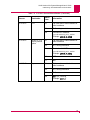
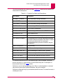
Table 1-1 lists the specifications of the AI198.
Table 1-1 Technical Specifications
Specification
Description
Installation
Requires one slot in an AI chassis.
Power
Consumption
16.5 W
Compliance
For use with AI UL listed AIswitch Series
Chassis.
1-3
AI198 Version 2.2x System Manager/User’s Guide
AI198 Overview: AI198 Functionality
AI198 Functionality
Menu Driven Configuration
The AI198 offers a menu-driven configuration interface. Default settings streamline
the initial configuration process and allow for quick reconfiguration.
The AI198 can be configured locally using a terminal at the craft port. You can also
configure the AI198 through your network.
Dedicated Asynchronous Craft Port
The AI198 uses the dedicated craft port on the AI130 alarm panel or the AI180
(backplane Revision 6 or higher).
This provides a local access point to the AI180 for initial diagnostic messages and to
affect system configuration and commands. The craft port may not be used to place
calls.
Background Connections
Background connections provide remote access between a system manager on a
network and the AI198. No asynchronous ports or special cables are required for
remote AI login and CAAML applications (see Network Parameters on page 4-21).
Most AI products have this feature. For information about individual card connections,
see the specific smart line card document.
A background connection is the equivalent to connecting to the craft port. All the
functions that can be performed at the craft port can be done with a background
connection, with the exception CTRL+l (lowercase L) for toggling on-demand logging.
For additional information, refer to the break/b id and shobgc commands in Chapter
8: Commands from the AI Prompt, and the CAAML option in Chapter 4: System
Configuration by Menu.
Activity/Alarm Log
The system can send information about system activity and alarm indications to a
system port. The data from this port can be used for system maintenance,
configuration balancing, and security and accounting systems information.
Backplane Alarms
Alarms are generated across the backplane and can be viewed on the craft port or on
any programmed port.
1-4
AI198 Version 2.2x System Manager/User’s Guide
AI198 Overview: AI198 Functionality
Call Routing
The AI180 can act as a gateway by making connections from one Smart Line Card to
another. The system automatically looks up an incoming call destination and routes
the call to the preconfigured destination in another network. Call routing is supported
by an alias macro language, multiplexed and aggregated TDSs, alternate routing, and
computed call parameters.
Autoswitching to Backup CLC
With redundant CLCs, the system can automatically transfer processing from the
active CLC to the backup CLC when necessary. For this feature to work, the CLC
selector switch on the noncabled side of the controlling chassis must be set to AUTO.
The swcpu command can force switching from the active CLC to the backup CLC.
Automatic CLC Update
Using menu item 1.11, the system can be set up to automatically configure a
secondary CLC when placed into an AI180 with an active CLC. These conditions are
required:
z
The AI180 power must be on
z
Only one operating CLC is mounted in the AI180
z
The CLC selector switch must be set to AUTO
z
Menu item 1.11 of the operating CLC must be set to on
z
Both CLCs must have the same software version.
When the secondary CLC is inserted into the AI180, the configuration of the active
CLC will then be copied to the secondary CLC. During the update process, the LOAD
LEDs on the faceplate of the secondary CLC displays an active pattern.
Also, if any changes are made in the active CLC configuration, these changes will
automatically be made in the backup CLC configuration.
EIA Modem Simulation for Connection
The system can program the disconnected and connected states of Electronic
Industries Association (EIA) signals. The system can also be programmed to toggle
these leads. The system can use EIA signaling to simulate modem style access to
host computers. These signaling options provide a secure and flexible connection to
any asynchronous host and modem port.
1-5
AI198 Version 2.2x System Manager/User’s Guide
AI198 Overview: Network Management Features
Network Management Features
In addition to menu and command-driven configurations, advanced configuration and
network management can be performed over the network.
Telnet Connections
You can use a Telnet connection to access the AI180 over a Local Area Network
(LAN) or Wide Area Network (WAN). This is essentially a remote version of the craft
port where you can input system configurations and commands but cannot place
calls.
Telnet sessions are faster than asynchronous connections and are better at handling
lengthy reports (such as DMPCFG output). Logging can be accomplished on any
Telnet session without any special configuration. Press CTRL+l (lowercase L) to
toggle logging on or off for the connection.
The Telnet session cannot be used to perform asynchronous file transfers for software
or configuration downloads or uploads.
FTP Connectivity
You can use File Transfer Protocol (FTP) to download or upload software or
configuration files to or from the AI198.
The AI198 FTP server conforms to the standards for FTP, and you should have FTP
client software on your networking computer. Note that some client packages do not
conform to all FTP standards and may not work properly with this system. If your FTP
client does not function as expected, contact Technical Support for suggestions.
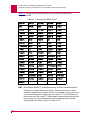
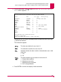
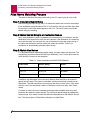
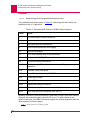
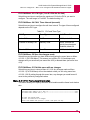
Supported FTP Commands
Table 1-2 is a list of FTP commands supported on the AI198. The commands are
issued transparently between the CLC and the client application and may not be
directly available.
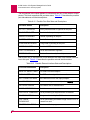
Table 1-2 Supported FTP Commands
1-6
Command
Description
dele
Allows you to delete a file. Currently, only the image
as.img can be deleted.
help
Provides help information.
list
Provides a directory listing of valid files on the CLC.
Arguments will be ignored.
mode
Stream is the only implemented transfer mode. Other
modes are not implemented.
AI198 Version 2.2x System Manager/User’s Guide
AI198 Overview: Network Management Features
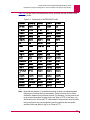
Table 1-2 Supported FTP Commands (Continued)
Command
Description
nlist
See list.
noop
Indicates no operation. The CLC returns an OK as a
response to this command.
pass
Allows you to specify the user password.
port
Allows you to specify the data connection port.
pwd
Allows you to print the current working directory. Since
the only directory available on the AI198 is the root
directory, “/” is sent as the response.
quit
The CLC terminates the FTP session and closes the
connection.
retr
Allows you to retrieve a file. The CLC transfers a copy of
the specified file to the user site. The file on the CLC is
unaffected.
stor
Allows you to store a file. The CLC accepts data from the
user site. This data is stored on the CLC in the specified
file. If the file already exists, its contents will be replaced
by the transferred data.
stru
File is the only implemented structure. Other modes are
not implemented.
type
Allows you to specify a data transfer type. These transfer
combinations are recognized:
z an ASCII, nonprint
z in Image, nonprint
z l8 Byte size can only be 8
All binary image files must be transferred in image (or
binary) mode.
user
Allows you to specify a user name.
xpwd
Allows you to print the working directory. See pwd.
1-7
AI198 Version 2.2x System Manager/User’s Guide
AI198 Overview: Network Management Features
SNMP Manageability
Simple Network Management Protocol (SNMP) is an industry standard protocol for
managing network elements. The SNMP agent on the AI198 allows management and
monitoring of the AI180 using a network manager such as AppliedView.
AppliedView features a Graphical User Interface (GUI) that you can use to configure
and manage an entire network of AI products, from card level to link level.
Alarm monitoring is also supported via SNMP and AppliedView. Many configurable
options on both the AI198 and AppliedView allow the alarm reporting mechanism to
be configured to the needs of the network manager.
Automatic Reboot
The AI198 now offers an automatic reboot feature after a system crash. This feature
is enabled only when no backup CLC exists.
AI2524 Configuration
When using secondary addressing on the Ethernet0 interface, the primary address
must be in the same network as the TFTP server. An example of secondary
addressing would be configuring the Ethernet0 interface for two networks (that is,
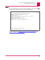
198.x.x.x and 192.x.x.x). The configuration for the Ethernet0 interface would look
similar to this:
Interface Ethernet0
ip address 198.30.36.1.255.255.255.0
ip address 192.30.36.1.255.255.255.0 secondary
In this example, the primary network is 198.30.36.1, and the secondary network is
192.30.36.1. You would have to configure the AI198 with an IP address in the
198.30.36 network to serve as the TFTP server for the AI2524.
Note: The AI198 supports TFTP configuration files up to 25K.
Firmware Upload/Download to CLC
You can update the internal software of the AI198 through downloads. Updates,
corrections, and enhancements can be delivered as software. In most cases, you can
install this software using a few keyboard commands.
Depending on your connectivity, you can load files from a floppy diskette on a
personal computer or your local network. This can be accomplished using an
asynchronous connection or using the AI198 built-in FTP capability.
1-8
AI198 Version 2.2x System Manager/User’s Guide
AI198 Overview: Network Management Features
Firmware Download to Smart Line Cards
Using the AI198, you can also download software to Smart Line Cards. You can
obtain software image updates from an external source such as a floppy disk or
computer network.
Configuration Upload/Download
The configuration upload/download feature lets you store and reload configuration
information via floppy disk or network, and transfer configurations between separate
networks. The AI180 can also back up and restore configurations for remote AI180s.
1-9
AI198 Version 2.2x System Manager/User’s Guide
AI198 Overview: Hot-Swap
Hot-Swap
Hot-swap is supported on the AI198 and on all Smart Line Cards in the AI180. By
completing the proper procedures, an inactive card may be pulled from the chassis
and replaced without having to power down the AI180.
Commands used in these procedures are described in detail in Chapter 8:
Commands from the AI Prompt.
AI2524 and AI294 Configuration Storage and Hot-Swap
The AI2524 and AI294 must have their configuration stored on the AI198 to insure the
ability to perform the hot-swap. When the AI2524 and AI294 boot, they use the
BOOTP protocol to obtain their IP addresses. The AI2524 and AI294 then use TFTP
to transfer their configuration information from the AI198 to the AI2524 and AI294.
Any changes made to the AI2524 or AI294 configuration must be stored back to the
AI198 to maintain full hot- swap capability. The following sections detail some options
for managing the AI2524 and AI294 configurations.
Always Modify the Configuration Using Menu 4.18
This option suggests that you use Menu 4.18 whenever you make modifications to
either the AI2524 or AI294 configuration. After you complete the modifications, you
can use the enabl command to reset the AI2524 and AI294. This allows the changes
to take effect.
Modify the Configuration on the AI2524/Store the Configuration on the
AI198
This option suggests that whenever you make modifications to the AI2524
configuration using the configuration mechanism (Telnet to the card and change the
configuration or access the console port), you must store the modifications on the
AI198. You can save the configuration to the AI198 using TFTP on the AI2524.
Modify the Configuration on the AI294/Store the Configuration on the
AI198
This option suggests that whenever you make modifications to the AI294
configuration using the AI294 configuration mechanism (Telnet to the card and
change the configuration or access the console port), you must store the
modifications on the AI198. You can save the configuration to the AI198 using TFTP
on the AI294.
1. After logging into the AI294 using Telnet or the console port, make the desired
configuration changes.
2. Disable BOOTP in the AI294 configuration.
3. Perform a warm or cold reset.
1-10
AI198 Version 2.2x System Manager/User’s Guide
AI198 Overview: Hot-Swap
4. Log onto the AI294 using Telnet or the console port.
5. Re-enable BOOTP.
6. Use the par-upld command to transfer the configuration to the AI198.
CLC Procedure
This procedure is for hot-swapping the CLC only. Do not perform this on smart line
cards.
CAUTION: Never remove the active CLC when its green SEL LED is on.
1. Determine which CLC is inactive. On an inactive CLC, the SEL LED is off.
2. Loosen the two locking screws holding the inactive CLC in place.
3. Firmly grasp the locking screws of the inactive CLC and pull the card out of the
AI180 chassis.
4. Insert the new CLC into the same slot in the AI180 chassis. Press it firmly into
place and tighten the two locking screws.
5. Reconnect all cables and connectors which were disconnected in step 2.
6. Enter the cpycnf command at the AI command prompt to copy the configuration
from the active CLC to newly connected backup CLC.
7. Be sure that the newly connected backup CLC is using the latest software. For
more information, see Chapter 6: Downloading Software and Configurations.
Smart Line Card Procedure
This procedure is for hot-swapping smart line cards only. Do not use this procedure
on your CLC. Note that the AI2524 and AI294 are unlike any other card in that you do
not have to manage the ports. Typically, you need to disable cards by using the
stpslc and disabl/c commands before you can remove them from the switch. The
AI2524 and AI294 do not require you to use these commands.
1. Log on to the AI180.
2. Enter this command at the AI command prompt to stop the smart line card:
stpslc baseport
baseport
is the baseport of the target smart line card.
1-11
AI198 Version 2.2x System Manager/User’s Guide
AI198 Overview: Hot-Swap
3. Type y for confirmation.
Note: Do not use the stpslc command for the AI2524 or AI294. If you type the
stpslc command for either card, the system displays one of these
messages:
>stpslc 00
Cards/ports will be restarted as follows:
Baseport Type
Status
Description
000*
AI2524 ENABLED
Ports/Cards marked with * are unaffected by this command.
4. Enter this command at the command prompt to disable the smart line card:
disabl/c baseport
baseport
is the baseport of the target smart line card.
Note: Do not use the disabl/c command for the AI2524 or AI294. If you type
the disabl/c command for either card, the system displays one of these
messages:
>disabl/c 00
Cards/ports will be restarted as follows:
Baseport Type
Status
Description
000*
AI2524 ENABLED
Ports/Cards marked with * are unaffected by this command.
5. Disconnect any cables and connectors attached at the smart line card’s faceplate.
If necessary, mark the position of each cable so that they can be reconnected to
the same port or connector without doubt.
6. Loosen the two locking screws holding the smart line card in place.
7. Firmly grasp the locking screws of the smart line card and pull the card out of the
AI180 chassis.
8. Insert the new smart line card into the same slot in the AI180 chassis. Press it
firmly into place and tighten the two locking screws.
9. Reconnect all cables and connectors which were disconnected in step 2.
1-12
AI198 Version 2.2x System Manager/User’s Guide
AI198 Overview: Hot-Swap
10. Enter this command at the command prompt to restart the smart line card:
enabl/c baseport
baseport
is the baseport of the target smart line card.
Note: For the AI2524 or AI294, when you type the enabl/c command, the
system displays this message:
>enabl/c 00
Cards/ports will be restarted as follows:
Baseport Type
Status
Description
000
AI2524 ENABLED
Are you sure you want to proceed? (Y/N) >
11. Type Y for confirmation.
1-13
AI198 Version 2.2x System Manager/User’s Guide
AI198 Overview: Hot-Swap
1-14
2
Quick-Start Configuration
This chapter describes the quick-start method for starting and testing the AI180.
Quick-start is a method for putting the AI180 into operation quickly. To perform a quick start, we
assume that you are starting with the default system parameters that were set at the factory.
Reinitializing to the default configuration is described in this chapter.
To use the quick-start method, you must first use the menu system to set up the desired
destinations and configure the ports that access those destinations.
Guide to this Chapter
Requirements
Connecting to the Craft Port
CLC Initialization
Basic Configuration
2-1
AI198 Version 2.2x System Manager/User’s Guide
Quick-Start Configuration: Requirements
Requirements
Before you begin:
2-2
z
Be familiar with navigating within the menus. See Navigating Menus on page 4-3
for instructions.
z
Be aware that quick-start does not take full advantage of the AI180 capabilities.
z
Set up your AI180 according to the AIswitch Hardware Manual.
AI198 Version 2.2x System Manager/User’s Guide
Quick-Start Configuration: Connecting to the Craft Port
Connecting to the Craft Port
When you receive your AI180 system, it has a simple initial configuration. This default
sets all ports to 9600 baud, 8 data bits, no parity, and 1 stop bit.
Under the default setup, logging (displaying log messages) is enabled on the craft
port. Note that this can be altered when you customize your configuration, sending
the log to another port that uses a different communication protocol. Quick-start
assumes, however, that you are viewing log output from the craft port.
If you are using a dumb Cathode Ray Tube (CRT) terminal, you only need to have
pins 2 (to transmit data), 3 (to receive data), and 7 (signal ground) connected. If your
cable does not work, the most probable cause is that the signals on pins 2 and 3 need
to be reversed. Try correcting this first. If you need additional information on terminal
wiring, see the AIswitch Hardware Manual.
Set the terminal speed to 9600 baud, 8 data bits, no parity, and 1 stop bit. See your
terminal operator manual for instructions on how to set these options. If you are using
a personal computer, you must have a terminal emulation program.
2-3
AI198 Version 2.2x System Manager/User’s Guide
Quick-Start Configuration: CLC Initialization
CLC Initialization
Setting for Redundant CLCs
The AI180 has the capability for redundant controller logic. The CLC selector switch
on the noncabled side of the chassis should be in the AUTO position to allow the
system to automatically switch to the backup CLC if necessary.
For systems not equipped with the a redundant CLC, the CLC selector switch should
be in the A or AUTO positions.
Only the panel switch on the controller chassis is used by the system; the panel
switches on expander chassis have no effect.
Power-Up Sequence for Expander Chassis
When powering up an AI180 with one or more expander chassis, make sure to turn
on all the expander chassis before turning on the controller chassis containing the
CLC card.
If the controller chassis comes up before the expander chassis, the ports in the
expander chassis may not be seen by the startup diagnostics and will not be available
for use. If this happens, push the BOOT button on the CLC in the controller chassis
and the system restarts properly.
System Reset Message
System reset occurs when power is initially applied to the unit or when the BOOT
button on the CLC is pressed. This message appears:
** AIswitch Reset—Running Diagnostics **
The message is sent to the craft port at 9600 baud, 8 data bits, no parity, and 1 stop
bit. This message prints on the craft port regardless of where the log port has been
programmed.
This message prints to provide some reliable way of telling that the system has been
restarted. Should the system fail any of the critical diagnostics, further system fault
information prints on the craft port. For this reason, a terminal or printer should always
be connected to the craft port, even if logging and configuration is normally performed
on a different port.
If the reset message does not appear, refer to the AIswitch Hardware Manual for
setup and wiring procedures.
CLC Initialization Sequence
Upon power up or reset, the CLC performs a sequence of diagnostic functions. The
results are displayed as each step is completed.
2-4
AI198 Version 2.2x System Manager/User’s Guide
Quick-Start Configuration: CLC Initialization
The remaining messages are directed to the log and/or craft port as configured in
Menu 1.1. If no log port is configured, these messages are sent to the craft port
regardless of its setting.
A example initialization report follows. In a fully operational system, this would be
followed by initialization messages from the various smart line cards and configured
links.
Example Initialization Report
The following is an example of an initialization report.
**AIswitch Reset - Running Diagnostics**
EEPROM checksum=7EB08D3D
**** (0) Initializing TOD clock...
**** (1) Reading TOD clock...
**** (2) Testing configuration version...
**** (3) Initializing log port...
**** (4) Testing line cards...
Card at base port 0 is functional
Card at base port 16 is functional
Card at base port 32 is functional
Card at base port 48 is functional
Card at base port 64 is functional
Card at base port 80 is functional
Card at base port 96 is functional
Card at base port 112 is functional
Card at base port 128 is non-functional
Card at base port 144 is non-functional
Card at base port 160 is non-functional
Card at base port 176 is non-functional
Card at base port 192 is non-functional
Card at base port 208 is non-functional
Card at base port 224 is non-functional
Card at base port 240 is non-functional
**** (5) Initializing alarm system...
**** (6) Logging system information...
@NODE-XXX 15:42:43 020596 Sev=F Base=Active CLC Msg:
*******AIswitch Restarted*******
@NODE-XXX 15:42:43 020596 Sev=F Base=Active CLC Msg:
Version 98CLC130.000053 (02/01/96 16:10:38) /DEB/180/DUAL/WTX
@NODE-XXX 15:42:43 020596 Sev=F Base=Active CLC Msg:
EEPROM checksum=7EB08D3D
@NODE-XXX 15:42:43 020596 Sev=F Base=Active CLC Msg:
Total number of online ports 068
@NODE-XXX 15:42:43 020596 Sev=F Base=Active CLC Msg:
This cpu is the A Processor, Switch is in AUTOMATIC
**** (7) Testing reconfiguration strings...
**** (8) Executing initialization strings...
**** (9)
Begin normal operation...
*CONNECTING NOW*
2-5
AI198 Version 2.2x System Manager/User’s Guide
Quick-Start Configuration: Basic Configuration
Basic Configuration
Logging in to AI
The craft port is automatically attached to the system manager’s account (destination
AI). If no password has been configured for this destination, the AI180 presents the
user with a command prompt.
If a password has been set (see menu item 2.13), you must type this password at the
craft port before access is allowed.
Reinitializing Configuration to Factory Defaults
You may want to reinitialize the EEPROM configuration database back to factory
defaults. You can then reconfigure the system using this as your base.
Before clearing the configuration database, it is highly recommended that you first
obtain listings of your current configuration parameters. A variety of commands are
available for this purpose (see Chapter 8: Commands from the AI Prompt). For
example, a hardcopy of the DMPCFG, STASLC, and SHOPRT 0-255 reports could be
invaluable. Also, having an electronic copy of the Active.ee file (via FTP) or the
DMPEE or DMPCFG reports make editing and restoring the reconfiguration much
easier.
Once you have obtained your reports, enter selcnf/c to initialize the configuration.
After you enter this command, this message appears on your screen:
Are you sure you want to proceed? (y/n)
CAUTION: The selcnf command reinitializes the system configuration. Any
previous configuration will be lost. The AI180 configuration will have to
be reentered from scratch or restored from backup.
After you enter this command, the AI180 automatically resets, and the current
configuration is deleted in favor of the factory defaults.
Alternately, you may send a CTRL+r from the craft port during the central AI180
initialization sequence any time before the message is printed.
Also note that commands entered in Menu 1.9.2 will be executed after this
reinitialization. If you wish to prevent this, you must send an ESC from the craft port
during the central AI180 initialization sequence.
2-6
3
Introduction to System
Configuration
This chapter describes different methods for logging in and setting up the system, and it defines
important user concepts.
The AI180 must be properly configured so that its components work together for your specific
network needs.To this end, AI provides a number of connection and configuration methods. You
can use any of the methods explained in this chapter to change the system configuration.
All configuration data is stored in a nonvolatile EEPROM memory, so it will not be erased if power
is interrupted.
The AI180 is shipped from the factory supplied with a default configuration for all the ports and
destination names. These default values appear on the initial menus and on the system
configuration worksheets. To configure the system using default values, see Chapter 2: QuickStart Configuration.
Guide to this Chapter
Terms
Configuration Methods
Data Entry Menu Items
Accessing the AI180
Account Profiles and User Account Security
Setting Up User Accounts
Managing User Accounts
Managing Permission Profiles
3-1
AI198 Version 2.2x System Manager/User’s Guide
Introduction to System Configuration: Terms
Terms
Ports, Links, Spans and TDSs
In the current documentation, the terms port and link refer to a single connection. A
TDS is one of the 256 data channels within the AI180.
Before the introduction of smart line cards, a connection always required two ports
and two TDSs. Because of this, most older literature and the menu system treat the
terms port and TDS as though they were identical.
In general, if a smart line card is being discussed, the term port means TDS unless
the context makes it clear that a physical connection is being referenced. Link and
span always refer to a single physical connection on a smart line card.
Destinations
A destination (also referred to as a class or class of service) is a named group of
attributes which may be applied to any number of TDSs. The destination name is
used for both the simplest forms of call routing and as the basis upon which
sophisticated call routing is built.
Aliases
Aliases are used for most call routing. They are required for all calls being routed from
one smart line card to another. For other calls, they provide a variety of necessary
features such as automatic call parameter generation.
Alias call processing is done in three stages. First, when a call is received from a
smart line card or user port, call routing strings attempt to match the call to an alias
name. Then the alias macro language is used to evaluate the incoming call
parameters and produce output parameters. Finally, the output parameters either
complete the call within the AI180 or continue the routing by placing an outgoing call.
Another feature of aliases is alternate routing. This allows the AI180 to reroute failed
calls along different paths, adding robust fault tolerance.
For more information, see these chapters:
3-2
z
Chapter 7: Call Routing
z
Appendix C: Reading Alias Macros
AI198 Version 2.2x System Manager/User’s Guide
Introduction to System Configuration: Configuration Methods
Configuration Methods
An extensive software system provides the system manager with maximum flexibility
in configuring the system. A wide variety of connections can be used for configuration.
The methods below are listed from the most fundamental to the more sophisticated
and automated:
z
Menu System
z
config Command
z
Configuration Via SNMP Manager
z
Configuration Upload/Download
Menu System
The AI180 offers a menu-driven configuration system, with default settings throughout
which allow you to streamline the initial configuration.
The AI180 can be configured locally using such tools as a terminal on the craft port.
Access to configuration menus and commands can also be accomplished by logging
in through your network. Methods of connection are discussed below.
config Command
The config command is very closely related to the menu system. It allows you to
make the same kind of changes to the AI180 configuration without actually entering
the menu system. It is not recommended for inexperienced AI198 users.
Enter the config command from the command prompt after connecting to the AI180.
You can type the config command followed by a series of menu, menu item, and
value arguments (keywords). These keywords identify the equivalent menu and menu
item you wish to configure and the value you wish to select.
For a detailed explanation of this command and keyword listing, see Appendix B:
The config Command.
Configuration Via SNMP Manager
SNMP is an industry standard protocol for managing network elements. The SNMP
agent on the AI198 allows configuration of the AI180 using a network manager such
as AppliedView.
AppliedView features a graphical user interface, allowing you to perform network
configuration, management, and monitoring.
For more information on using SNMP, see Chapter 5: Configuration by SNMP.
Additional information can also be found in the AppliedView AI Product Element
Management System Installation and Administration document.
Configuration Upload/Download
3-3
AI198 Version 2.2x System Manager/User’s Guide
Introduction to System Configuration: Configuration Methods
The configuration upload/download feature lets you work with the whole configuration.
You can store and reload configuration information via floppy disk or network or even
to transfer this information between separate networks.
This also provides the ability to both back up and restore configurations for remote
AI180s. This feature is covered in Chapter 6: Downloading Software and
Configurations.
3-4
AI198 Version 2.2x System Manager/User’s Guide
Introduction to System Configuration: Data Entry Menu Items
Data Entry Menu Items
Strings
ASCII strings are used in many menu items. They may contain the characters zero
through nine, A through Z, and any punctuation mark except the plus sign ( + ),
asterisk ( * ), and comma ( , ). In most menu items, both string and extended string
inputs are converted to uppercase. However, there are cases where the entered case
is preserved.
Extended Strings
In addition to the printable ASCII characters, extended strings can contain all other
characters with values from 1 to 254. Character values 0 and 255 are reserved
internally as delimiters. While some nonprintable characters may be typed directly
from a terminal, the preferred method of entry is indicated in the following sections.
Angle brackets are required for each included control character. Because the <
character is used in this special manner, it cannot be used normally in a string, such
as to indicate less than. This is especially important to remember when entering alias
macro strings. To include a less than character in a string, type <<. This will be
reduced to a single < when the string is evaluated.
To terminate an extended string, place a null character <0> after it. For more
information on character codes, refer to Appendix A: ASCII Codes.
Format
value
Parameters
value
This argument is a decimal number from 1 to 254.
Decimal Numbers
These menu items allow the entry of the characters zero to nine. Frequently, there are
limitations on both the minimum and maximum values which may be entered.
Hexadecimal Numbers
These menu items contain base 16 numbers. In addition to the characters zero to
nine, characters A to F represent the numbers 10 to 15. They are frequently used as a
more compact representation of a binary (base 2) number.
Internet Addresses
Internet addresses consist of four decimal numbers separated by periods (for
example: 89.2.3.10). In general, each of the numbers can range from 0 to 255.
3-5
AI198 Version 2.2x System Manager/User’s Guide
Introduction to System Configuration: Accessing the AI180
Accessing the AI180
The AI180 may be accessed in any of these ways:
z
Access Via the Craft Port
z
Access Through Background Connections
z
Access Via Telnet
Access Via the Craft Port
There is a dedicated craft port on the AI130 alarm panel and the AI180 chassis
(backplane Revision 6 or higher). A terminal properly connected to this physical port
provides communication with the CLC for system configuration, monitoring, and
logging output.
The craft port cannot be used to place calls through the system to other ports.
Connection
A dumb terminal or any computer running terminal emulation software can be
connected to the physical craft port.
Communications with the craft port must be set to 8 bits per character, no parity, and 1
stop bit. The craft port also responds to XON/XOFF flow control.
During normal operation, the craft port appears to be port 256 on the system. The
screen prompt will refer to it as craft port.
Logging In
The craft port is automatically attached to the system manager’s account (destination
AI). If no password has been configured for this destination, the craft port will
automatically be logged into the AI180 and will present you with a command prompt.
If a password has been set (see menu item 2.13), you will be prompted to enter this
password at the craft port before you are given access.
Logging Out
Where a password has been configured for the AI destination, the system manager
should log out after completing work on the craft port. From the command prompt,
type one of these commands: bye, lo, logoff, or logout.
The Error/Activity Log
The craft port may receive the error log in parallel with the log port set in menu item
1.1.2. It will also receive log information when the log port is disabled. The craft port
logging state is initially set in menu item 1.1.9. It may be toggled on or off by pressing
CTRL+l (lowercase L) at the terminal.
3-6
AI198 Version 2.2x System Manager/User’s Guide
Introduction to System Configuration: Accessing the AI180
Craft Port Character Usage
Communications with the craft port are 8 bit, no parity, 1 stop bit. When characters are
received, the high bit is cleared. These are legal entries. All others echo a CTRL+g
(bell).
Table 3-1 Legal Entries for Craft Ports
Entry
Description
<Break>
Use this entry to terminate a connection. Discard all
input/output.
XOFF
Use this entry to stop sending characters.
XON
Use this entry to start sending characters.
CTRL+l
(lowercase L)
Use this entry to toggle the logging state. The initial logging
state is set in menu item 1.1.9.
CTRL+o
Use this entry to flush the output buffer.
BACKSPACE or
DELETE
Use these entries to remove the previous character from the
input buffer. It echoes BACKSPACE-SPACE-BACKSPACE to
clear the character.
CTRL+u
Use this entry to remove all previous characters from the line.
Echoes BACKSPACE-SPACE-BACKSPACE multiple times.
RETURN or
<Linefeed>
Use these entries to signal the end of the line, to cause a
carriage return and line feed combination to be echoed, and to
cause the input to be evaluated.
SPACE or
<Tilde>
Use these entries to add a character to the line buffer.
Access Through Background Connections
Background connections provide remote access to the AI198 from a network. No
asynchronous ports or special cables are required for remote AI login and CAAML
applications. Most AI products can use this feature. See your specific smart line card
document for compatibility and details.
A background connection is the remote equivalent of connecting to the craft port. All
the functions that can be performed at the craft port can be done with a background
connection with the exception of CTRL+l (lowercase L) for toggling on-demand the
ability to log on and off.
3-7
AI198 Version 2.2x System Manager/User’s Guide
Introduction to System Configuration: Accessing the AI180
Connecting
To use background connections, your terminal must have an access path to a smart
line card capable of communicating on the AI180 backplane. See your specific smart
line card document for backplane compatibility, as well as for installation and
configuration instructions.
Next, you must establish an alias which directs the connection to the AI destination on
the AI198. This can be done from the menu system. Refer to Chapter 7: Call Routing.
To create an alias:
1. Specify the incoming called address. This can be done in menu item 8.1.
2. Select simple alias translation as the translation type in menu item 8.2.1.
3. Specify the destination in menu item 8.3:
Here is an X.25 example:
Menu 8
01 Alias name - 1001001000
02+Simple alias translation
03 Destination - AI
In this example, any incoming call with a called address of 1001001000 would be
directed to the AI destination, establishing a background connection.
Logging In
Once the connection is established, you will be logged into destination AI. If your
login requires, you may be prompted to enter a password before you can gain access.
Once logged in, you can perform configuration and command functions.
Logging Out
The normal CLC disconnection commands (bye, lo, logoff and logout) will
terminate the background session.
Error/Activity Log
This function is not normally available from a background connection.
Character Usage
The editing features are the same as those found on the craft port.
Checking Status
The status of all background connections can be obtained through the command
shobgc on page 8-95.
3-8
AI198 Version 2.2x System Manager/User’s Guide
Introduction to System Configuration: Accessing the AI180
Removing Sessions
Enter the break/b bid command to remove a background connection. bid is the
background connection number.
Access Via Telnet
Telnet provides access to the AI180 over a LAN or WAN. This is essentially a remote
version of the craft port which enables you to affect system configuration and
commands. Telnet, however, is much faster than asynchronous connections and is
better at handling lengthy reports (such as DMPCNF output).
The Telnet session cannot be used to perform asynchronous file transfers for software
or configuration downloads or uploads.
Connecting
The AI198 can be accessed in the same manner as any other Telnet capable device.
Using Telnet software on a computer that resides on the same TCP/IP network as
your AI180, you establish the session by connecting to the AI198 IP address. See the
instructions from your specific Telnet package for details.
Enter the AI198 IP address in the Network Parameters on page 4-21 of Chapter 4:
System Configuration by Menu. If you do not know the IP address of the AI198, log in
using other means and consult the menu to obtain the current address information.
Logging In
Once the connection is established, the Enter
must enter a valid destination.
destination name
prompt appears. You
If your login requires a password, the password prompt appears. Note that this is not
the destination password but the shell-override password as entered in menu item
2.14 during system configuration.
Only three incorrect login attempts are allowed before the connection is broken. Both
incorrect and correct login attempts are logged.
Once logged in, you may perform configuration and command functions.
Logging Out
These commands will terminate the Telnet session: bye, lo, logoff, and logout.
Error/Activity Log
Logging can be done without any special configuration. Press CTRL+l (lowercase L)
to toggle between logging on or off for the connection.
Character Usage
The editing features are the same as those found on the craft port.
3-9
AI198 Version 2.2x System Manager/User’s Guide
Introduction to System Configuration: Accessing the AI180
Timers
Certain Telnet functions have associated activity timers. The session will be
disconnected if an activity timer expires.
The initial activity timer is 30 seconds for these states:
z
Login
z
Waiting_for_password
z
Password
The activity timer for the connected state is 4 hours if logging is not turned on and
unlimited if logging is enabled.
Checking Status
The status of all Telnet connections can be obtained through the command shell on
page 8-94. Shell connection numbers will appear with the newest connections at the
top of the list.
The shell ID number will roll over at 2^32.
Removing Sessions
Type the break/s sid command to remove a Telnet connection. sid is the shell
connection number.
Delay of Output
Some commands can cause the Telnet session to appear inactive for an extended
period. Command processing takes place as input is parsed, but output is not handled
until later. This can be particularly noticeable when creating or restoring a DMPCFG
report.
3-10
AI198 Version 2.2x System Manager/User’s Guide
Introduction to System Configuration: Account Profiles and User Account Security
Account Profiles and User Account Security
The AI198 allows you to configure or modify account profiles, account security
profiles, and account passwords, and determine other logins to the AI180. Add
account profiles to the account profile database as needed after configuration.
Note: The AI198 can access up to 120 account profiles.
Permission Profiles and Default Commands
The AI198 allows user-defined security profiles. Each security profile configures
specific commands allowed to be executed with that profile. When user accounts are
configured, each user must be assigned a security profile, thereby defining the
specific AI198 commands a particular user may use. The account supervisor can
create, delete, edit, and list the permission profiles.
Users may be added with any permission profile which governs the commands they
are allowed to execute. These tables list the default commands that can be executed
by each of the four default permission profiles provided by AI.
Table 3-2 lists the default commands that can be executed with the STATUS
permission profile.
Table 3-2 Commands for STATUS Profile
active
alrsho
bye
clist
dhold
dmpee
help
inv
ioact
lists
lo
logoff
logout
lstdsb
menuro
netsta
password
plist
repeat
shell
shobgc
shocls
sholog
shoprt
slist
stacls
staeia
staprt
staslc
stat
states
status
tftpstat
tmract
*tnlogin
watcpu
Note: Note that the asterisk (*) located before some of these commands denotes
that they are functions and not commands. These functions can be either
enabled or disabled for a particular account. For example, you may want to set
up an account that does not allow logins via Telnet or FTP. In this case, you
would remove the Telnet and FTP commands for the particular account profile
being configured. Any user assigned to use the particular account profile
would not have the ability to log in via Telnet or FTP.
3-11
AI198 Version 2.2x System Manager/User’s Guide
Introduction to System Configuration: Account Profiles and User Account Security
Table 3-3 lists the default commands that can be executed with the MGMT
permission profile.
Table 3-3 Commands for MGMT Profile
active
alrclr
alrset
alrsho
blast
bnc
break
bye
cfgmsg
clcip
clist
clr
clrals
clsoff
clson
commstr
config
cpycnf
cpycrd
debug
dep
dhold
disabl
dmpcfg
dmpee
dmpslc
dump
dwnld
eb
eed
eesize
enabl
ex
fast
flush
*ftplogin
help
inv
ioact
leds
lists
lo
lock
loglvl
logoff
logout
loop
lstdbs
mcon
menu
menuro
netclr
netsta
password
pick
plist
prtdsc
pstat
repeat
reset
restee
selcnf
send
shell
shobgc
shocls
sholog
shoprt
*slclogin
slist
stacls
staeia
staprt
staslc
stat
states
status
stpslc
swcpu
telnet
test
tftpstat
time
tmract
*tnlogin
tstini
unlock
update
watcpu
winslc
wndrct
Note: Note that the asterisk (*) located before some of these commands denotes
that they are functions and not commands. These functions can be either
enabled or disabled for a particular account. For example, you may want to set
up an account that does not allow logins via Telnet or FTP. In this case, you
would remove the Telnet and FTP commands for the particular account profile
being configured. Any user assigned to use the particular account profile
would not have the ability to log in via Telnet or FTP.
3-12
AI198 Version 2.2x System Manager/User’s Guide
Introduction to System Configuration: Account Profiles and User Account Security
Table 3-4 lists the default commands that can be executed with the SUPERVISOR
permission profile.
Table 3-4 Commands of SUPERVISOR Profile
account
accountp
active
alrclr
alrset
alrsho
blast
bnc
break
bye
cfgmsg
clcip
clist
clr
clrals
clsoff
clson
commstr
config
cpycnf
cpycrd
debug
dep
dhold
disabl
dmpcfg
dmpee
dmpslc
dump
dwnld
eb
eed
eesize
enabl
ex
fast
flush
*ftplogi
n
help
inv
ioact
leds
lists
lo
lock
loglvl
logoff
logout
loop
lstdbs
mcon
menu
menuro
netclr
netsta
password
pick
plist
prtdsc
pstat
repeat
reset
restee
selcnf
send
shell
shobgc
shocls
sholog
shoprt
*slclogi
n
slist
stacls
staeia
staprt
staslc
staslc
states
status
stpslc
swcpu
telnet
test
tftpstat
time
tmract
*tnlogin
tstini
unlock
update
watcpu
who
winslc
wndrct
Note: Note that the asterisk (*) located before some of these commands denotes
that they are functions and not commands. These functions can be either
enabled or disabled for a particular account. For example, you may want to set
up an account that does not allow logins via Telnet or FTP. In this case, you
would remove the Telnet and FTP commands for the particular account profile
being configured. Any user assigned to use the particular account profile
would not have the ability to log in via Telnet or FTP.
3-13
AI198 Version 2.2x System Manager/User’s Guide
Introduction to System Configuration: Account Profiles and User Account Security
Table 3-5 lists the default commands that can be executed with the FTP permission
profile.
Table 3-5 Commands for FTP Profile
bye
*ftplogin
lo
logoff
logout
Note: Note that the asterisk (*) located before some of these commands denotes
that they are functions and not commands. These functions can be either
enabled or disabled for a particular account.
Table 3-6 contains a list of password requirements and a description for each.
Table 3-6 Password Requirements Descriptions
3-14
Password Requirement
Description
240
Maximum number of characters for passwords
1
Minimum number of characters for passwords
Any printable character
Accepted characters for passwords
Not case sensitive
Case sensitivity
AI198 Version 2.2x System Manager/User’s Guide
Introduction to System Configuration: Setting Up User Accounts
Setting Up User Accounts
These procedures outline how to set up a user account.
1. Use the accountp/a command sequence to create a permission profile that will
contain the commands to be used by a particular user.
This step is optional if a permission profile already exists and contains the
commands to be used by the specified user.
2. Use the account/a command sequence to add a new user account.
3. Log on to the AI180.
You will have access to the commands specified in your assigned permission
profile.
Refer to sections Managing User Accounts and Managing Permission Profiles of this
chapter, and Chapter 8: Commands from the AI Prompt for more detailed
information.
3-15
AI198 Version 2.2x System Manager/User’s Guide
Introduction to System Configuration: Managing User Accounts
Managing User Accounts
These procedures detail an example of the commands you might use to manage a
user account.
1. Use the account/a command sequence to add a new user account. Enter the
following.
account/a username pswd permprofname
username is the username of the account you want to add. pswd is the password
of the user. permprofname is the name of the permission profile to use. A screen
similar to this appears:
>account/a adam adam profile1
ACCOUNT/A usrname pswd perm - to add account
ACCOUNT/D usrname - to delete account
ACCOUNT/L - to list accounts
NODE-XXX AIswitch Shell Connection
8
2. Use the account/l command sequence to list the configured user accounts and
their permission status. Enter the following:
account/l
When you type the account/l command sequence, a screen similar to this
appears:
>account/l
User Account Database
T with STATUS permission
W with WONG permission
JETSU with SUPERVISOR permission
GUY with SUPERVISOR permission
NODE-XXX AIswitch Shell Connection
8
3. Use the account/d command sequence to delete a user account. Enter the
following:
account/d username
username is the username of the account you want to delete.
When you type the account/d command sequence, a screen similar to this
appears:
>account/d guy
Account deleted.
NODE-XXX AIswitch Shell Connection
3-16
8
AI198 Version 2.2x System Manager/User’s Guide
Introduction to System Configuration: Managing Permission Profiles
Managing Permission Profiles
These procedures detail an example of the commands you might use to manage a
permission profile.
1. Use the accountp/a command sequence to add a new permission profile to the
AI180. Enter the following:
accountp/a [new prof name] [existing prof name]
new prof name is the name of the profile being created. existing prof name is
status, mgmt, supervisor, ftp, or user-defined.
A screen similar to this appears:
>accountp/a profile1 status
Permission profile added
NODE-XXX AIswitch Shell Connection
8
A new permission profile is always based on a default permission profile or an
existing permission profile.
The four default permission profiles are status, mgmt, supervisor, and ftp. The
accountp command accepts one of these names or the name of a previously
configured profile name for the existing profile name menu item. The new profile
name menu item may not be status, mgmt, supervisor, ftp, or the name of an
existing command profile. Successfully executing this command creates a new
permission profile which may then be modified by using the accountp/e
command.
3-17
AI198 Version 2.2x System Manager/User’s Guide
Introduction to System Configuration: Managing Permission Profiles
2. Use the accountp/e command sequence to edit or modify a permission profile.
Enter the following:
accountp/e existing profile name +/- command
existing profile name is the name of an existing profile. +/- command allows
you to add or delete a command to or from a profile.
A screen similar to this appears:
>accountp/e profile1 - stat
PROFILE1 permission profile modified
NODE-XXX AIswitch Shell Connection 8
Use this command sequence to edit a permission profile. When you edit a
permission profile, a command is added or deleted from the profile. Use the +
operator to add a command to the profile. Use the - operator to delete a
command from the profile.
When a command is contained within a profile, it may be executed by a user
assigned to the command profile. Multiple edits may be executed on the same
command line by repeating +/- command sequence.
3. Use the accountp/d command sequence to delete a permission profile. Enter the
following:
accountp/d existing profile name
existing profile name is the name of the profile to delete.
A screen similar to this appears:
>accountp/d profile1
Permission deleted
NODE-XXX AIswitch Shell Connection
0
Use this command sequence to delete the specified permission profile. If any
users are assigned to the permission profile you want to delete, a list of those
users will be printed. If any of these users log in to the AI180, their permission
profile will default to the status profile.
Note: The default profiles (status, mgmt, supervisor, and ftp) cannot be deleted.
3-18
AI198 Version 2.2x System Manager/User’s Guide
Introduction to System Configuration: Managing Permission Profiles
4. Use the accountp/l profile name command sequence to list the commands
and users assigned to a specified permission profile. Enter the following:
accountp/l profile name
profile name is the name of a profile to list.
A screen similar to this appears:
>accountp/l profile1
Permission Profile: PROFILE1
User List:
Commands:
ACTIVE
ALRSHO
BYE
CLIST
DMPEE
HELP
INV
IOACT
LO
LOGOFF
LOGOUT
LSTDSB
NETSTA
PASSWORD
PLIST
REPEAT
SHOBGC
SHOCLS
SHOLOG
SHOPRT
STACLS
STAEIA
STAPRT
STASLC
STATES
STATUS
TFTPSTAT
TMRACT
WATCPU
NODE-XXX AIswitch Shell Connection 1
DHOLD
LISTS
MENURO
SHELL
SLIST
STAT
TNLOGIN
5. Use the accountp/l command to list the commands and users in all configured
permission profiles. Enter the following:
accountp/l
When you type the accountp/l command, a screen similar to this appears:
>accountp/l
Permission Profile: PROFILE1
User List:
Commands:
ACTIVE
ALRSHO
BYE
CLIST
DMPEE
HELP
INV
IOACT
LO
LOGOFF
LOGOUT
LSTDSB
NETSTA
PASSWORD
PLIST
REPEAT
SHOBGC
SHOCLS
SHOLOG
SHOPRT
STACLS
STAEIA
STAPRT
STASLC
STATES
STATUS
TFTPSTAT
TMRACT
WATCPU
NODE-XXX AIswitch Shell Connection 3
Permission Profile: PROFILE2
User List:
Commands:
ACTIVE
ALRSHO
BYE
CLIST
DMPEE
HELP
INV
IOACT
LO
LOGOFF
LOGOUT
LSTDSB
NETSTA
PASSWORD
PLIST
REPEAT
SHOBGC
SHOCLS
SHOLOG
SHOPRT
STACLS
STAEIA
STAPRT
STASLC
STATES
STATUS
TFTPSTAT
TMRACT
WATCPU
NODE-XXX AIswitch Shell Connection 3
DHOLD
LISTS
MENURO
SHELL
SLIST
STAT
TNLOGIN
DHOLD
LISTS
MENURO
SHELL
SLIST
STAT
TNLOGIN
3-19
AI198 Version 2.2x System Manager/User’s Guide
Introduction to System Configuration: Managing Permission Profiles
6. Use the accountp/n command to list the names of all permission profiles. Enter
the following:
accountp/n
When you type the accountp/n command, a screen similar to this appears:
>accountp/n
Permission Profile Names:
STATUS
MGMT
SUPERVISOR
TEST1
T
T T
NODE-XXX AIswitch Shell Connection 8
3-20
FTP
PROFILE1
WONG
4
System Configuration by Menu
This chapter describes how to navigate and configure the AI198 menu system.
You can use this menu system to configure the AI198 or to view the current configuration.
Guide to this Chapter
Starting and Ending a Menu Session
Navigating Menus
Configuring the AI198
4-1
AI198 Version 2.2x System Manager/User’s Guide
System Configuration by Menu: Starting and Ending a Menu Session
Starting and Ending a Menu Session
Starting a Menu Session
To access the AI198 menu system:
1. Log onto the AI198.
2. At the command prompt (>), enter menu. The Main Menu appears.
>menu
Main Menu
01+Configure options affecting the system as a whole
02+Create, delete, or modify a destination name
03+Display all destination names
04+Configure cards
05+Set or remove connection restrictions based on port numbers
06+Display all connection restrictions
07+Configure slot density
08+Configure the alias translation table
09+Display the list of alias translation entries
10+Configure the BOOTP table
21 Exit the configuration menu system
Enter item number and optional ",value" then push <CR> key
>
Ending a Menu Session
To end a menu session:
1. In the Main Menu, enter 21.
2. At the command prompt, enter logoff.
Note: You can also log off by entering lo, bye, or logout.
4-2
AI198 Version 2.2x System Manager/User’s Guide
System Configuration by Menu: Navigating Menus
Navigating Menus
Menu Names
All menus following the Main Menu have a numerical name at the top right corner of
the menu. This numerical name shows your location within the menu hierarchy. Each
digit in the name represents a menu item that was previously selected. For example,
Menu 4.2 indicates that menu item 4 was selected, and then menu item 2 was
selected.
Menu 4.2
Selecting Menu Items
Each menu contains a list of numbered menu items that represent parameters that
the system manager can configure. In general, to make a selection, type the number
of the desired menu item and press ENTER. For some menu items, more data is
required. When entering a menu item number it is not necessary to include leading
zeros. For example, you can type 2 instead of 02; both ways will work.
Types of Menu Items
These menu types are used on the AI198:
z
Submenus
z
Toggle Menu Items
z
Data Menu Items
z
Menu Item Functions
Submenus
A plus sign (+) next to a menu selection indicates that there is a submenu.
For example, Menu 1.13 reads:
13+Time and Date format is hh:mm:ss mmddyy
Some submenus ask you to make a selection from a list and then redisplay the
previous menu showing your selection. Other submenus have their own submenus
that request additional information. After saving your entries, the top-level menu
redisplays.
4-3
AI198 Version 2.2x System Manager/User’s Guide
System Configuration by Menu: Navigating Menus
Toggle Menu Items
Toggle menu items show two or more values that can be selected for a parameter.
Toggle menu items have an asterisk (*) next to their menu item number. To select a
value, type the menu item number and press ENTER. Each time you type the menu
item number and press ENTER, you toggle to the next selection.
In this example, menu item 02 is a toggle menu item:
02*The display of connection information on user terminals is turned----------ON
For menu item 02*The display of connection
you can toggle between ON and OFF.
information on user terminals is turned,
Data Menu Items
Data menu items request text entries (such as destination names and card
descriptions) or numeric values (such as port numbers and IP addresses).
To enter information in a data menu item, type the menu item number followed by a
comma, then the configuration information, and press ENTER.
To change what you have typed, use the BACKSPACE key to backup to the desired
position in the text and retype the changes. However, once you press the ENTER key,
changes can be made only by selecting that menu item and reentering the data.
In this example the menu item requests the destination name that you want to add,
change, or delete.
01
The destination name to add, change or delete------------296S4
To enter the destination name 296S4, you would type 1,296S4 and press ENTER.
The menu reappears showing the destination name that you entered.
01
The destination name to add, change or delete------------296S4
To change configuration data that has been entered for a menu item, type the menu
item number followed by a comma, then enter the new data.
4-4
AI198 Version 2.2x System Manager/User’s Guide
System Configuration by Menu: Navigating Menus
Menu Item Functions
Menu item functions appear at the bottom of each menu. Menu items 20 and 21 are
common functions throughout the AI198. This sample screen shows the menu items,
and Table 4-1 describes them.
20 Save the changes made
21 Exit this menu with no changes
Table 4-1 Menu Item Descriptions
Menu Item
Menu Item Description
20
Saves any updated configurations before exiting the menu.
21
Exits the menu without saving any changes. All items on the menu
return to the previously configured values.
Note: In order to exit a menu without saving changes, you must use
this menu item; using keyboard shortcuts will not allow the
CLC to properly free up the memory that was allocated
during menu navigation.
Entering Multiple Menu Commands
You can specify multiple menu commands on a single line, rather than accessing
submenus level by level. Enter each command separated by a blank space. For
example, to prevent ports 16 to 48 from accessing the XDOT32 destination while in
the Main Menu, enter the following command:
5 1 16 3,xdot32
In the first pair of numbers, 5 selects menu 5 and 1 selects menu item 5.1 (lowest port
number to be restricted). The next number, 16, is the value for the lowest port on the
card (you only need to specify the low port; the high port for the card is automatically
inserted). Finally, 3 selects Menu 5.3 (destination that these ports cannot access), and
xdot32 is the name of the destination.
The config commands Save (-) and End (.) abbreviations can also be used. See
Appendix B: The config Command for details.
Entering AI Commands from the Menu System
AI commands can be performed from the menu system by preceding the command
with an exclamation point (!):
!active
The !active command displays the active TDS connections on the AI180. Press
ENTER to redisplay the current menu.
4-5
AI198 Version 2.2x System Manager/User’s Guide
System Configuration by Menu: Navigating Menus
See the Chapter 8: Commands from the AI Prompt for details.
The following keys (listed in Table 4-2) are used to edit command lines:
Table 4-2 Keys to Edit Command Lines
4-6
Key
Function
Up and Down arrow keys
Recalls previous commands that
were issued on the AI198. The
AI198 saves 20 commands in its
history per connection.
Left and Right arrow keys
Moves through the command you
want to edit.
CTRL+k key
Removes all characters after the
cursor.
CTRL+u key
Removes all characters before the
cursor.
HOME key
Moves the cursor to the beginning
of the line.
END key
Moves the cursor to the end of the
line.
PAGE DOWN key
Moves the cursor to the last, or
newest, command.
PAGE UP key
Moves the cursor to the first, or
oldest, command.
BACKSPACE key
Removes the character to the left of
the cursor.
DEL key
Removes the current character.
AI198 Version 2.2x System Manager/User’s Guide
System Configuration by Menu: Configuring the AI198
Configuring the AI198
The following sections provide you with procedures for configuring the AI198. Refer to
Appendix D: Menu 4.2: Configure as... for assistance on configuring Smart Line
Cards.
The configuration process will take you step-by-step through the menu system,
covering these topics:
z
Menu 1: Configure Options Affecting the System as a Whole
z
Menu 2: Create, Delete, or Modify a Destination Name
z
Menu 3: Display all Destination Names
z
Menu 4: Configure Cards
z
Menu 5: Set or Remove Connection Restrictions Based on Port Numbers
z
Menu 6: Display all Connection Restrictions Based on Port Numbers
z
Menu 7: Configure Slot Density
z
Menu 8: Configure the Alias Translation Table
z
Menu 9: Display the List of Alias Translation Entries
z
Menu 10: Configuring the BOOTP Table
4-7
AI198 Version 2.2x System Manager/User’s Guide
System Configuration by Menu: Menu 1: Configure Options Affecting the System as a Whole
Menu 1: Configure Options Affecting the System as a
Whole
Menu 1 allows you to set options that affect the system as a whole and are not aimed
at a specific terminal or destination.
The menu items include these configuration procedures:
z
Set Log and Alarm Thresholds
z
Configuring User Terminals
z
AIswitch Commands Issued upon Restart
z
AIswitch Commands Issued After Configuration Restart
z
Display of Destination Names and Automatic CLC Update
z
Network Parameters (including IP and router address configuration)
z
Time and Date Format
z
SNMP Trap Table
z
Configure Banner
z
SNTP Configuration
z
Login Security Configuration (including RADIUS and TACACS+)
z
CLC Trap
z
Exiting Menu 1
These parameters are usually configured first, but they can be configured at any time.
To configure options affecting the entire system:
1. Log onto the AI198.
4-8
AI198 Version 2.2x System Manager/User’s Guide
System Configuration by Menu: Menu 1: Configure Options Affecting the System as a Whole
2. At the command prompt (>), enter menu. The Main Menu appears.
>menu
Main Menu
01+Configure options affecting the system as a whole
02+Create, delete, or modify a destination name
03+Display all destination names
04+Configure cards
05+Set or remove connection restrictions based on port numbers
06+Display all connection restrictions
07+Configure slot density
08+Configure the alias translation table
09+Display the list of alias translation entries
10+Configure the BOOTP table
21 Exit the configuration menu system
Enter item number and optional ",value" then push <CR> key
>
3. Enter 1 to select
appears.
01+Configure options affecting the system as a whole.
Menu 1
Menu 1
01+Set log and alarm thresholds
02*The display of connection information on user terminals is turned---------ON
03 The duration of a long break sequence in 1/64 seconds-------------0000000120
04*The automatic baud rate detection system is turned------------------------ON
05*Printing of a destination name menu on user terminals is turned-----------ON
06*Allow ports of different speeds to be connected (down speed)--------------ON
07 The designator for this node is----------------AI198
08*Allow dual CPUs to automatically switch if fault--------------------------ON
09+AIswitch automatic commands
10*The display of destination names in four columns is turned---------------OFF
11*Automatic CLC update is--------------------------------------------------OFF
12+Network parameters
13+Time and Date format is hh:mm:ss mmddyy
14+SNMP Trap Table
15+Configure Banner
16+SNTP Configuration
17+Login Security Configuration
18 Interval of the faulted primary CLC trap (0..65535 min.)---------------00000
20 Save the changes made
21 Exit this menu with no changes
Enter item number and optional ",value" then push <CR> key
4-9
AI198 Version 2.2x System Manager/User’s Guide
System Configuration by Menu: Menu 1: Configure Options Affecting the System as a Whole
Set Log and Alarm Thresholds
This section is specific to Menu 1.1. However, any changes made in this menu will not
take effect until you have completed the Menu 1 configuration, and have selected
Menu 1.20 (see Exiting Menu 1).
To continue Menu 1 configuration:
1. From the Main Menu, enter 1 to select 01+Configure
as a whole.
2. From Menu 1, enter 1 to select
appears:
options affecting the system
01+Set log and alarm thresholds.
Menu 1.1
Menu 1.1
01*The activity and alarm log is turned-------------------------------------OFF
02 The activity and alarm log prints on port number-------------------------000
03 Activity log severity threshold is-----------------------------------------1
04 Minimum minor alarm severity threshold is----------------------------------2
05 Maximum minor alarm severity threshold is----------------------------------4
06 Minimum major alarm severity threshold is----------------------------------5
07 Maximum major alarm severity threshold is----------------------------------9
08+Craft baud rate is 9600 baud
09*Craft log echoing default is----------------------------------------------ON
10 CAAML routing string 11 CAAML idle timer (1..255 sec, 0=disabled)--------------------------------010
12 CAAML retry timer (1..255 sec, 0=disabled)-------------------------------010
.
.
20 Retain these changes for saving in Menu 1
21 Exit this menu with no changes
Enter item number and optional ",value" then push <CR> key
3. Enter 1 to toggle ON or OFF the activity and alarm log. The default is
selected, an activity log will not be available.
ON.
If
OFF
is
The most recent log information is available using the sholog command.
Note: The log port and the sholog command will not work if the designated port
is set to autobaud, if the port has a destination name and cannot initiate
calls, or if the port is turned off.
4. Type 2, press SPACEBAR or ( , ), type port_number, and press ENTER to
identity the port number to receive the activity and log alarm. For Example, 2 16
provides this screen change:
02 The activity and alarm log prints on port number-------------------------016
4-10
AI198 Version 2.2x System Manager/User’s Guide
System Configuration by Menu: Menu 1: Configure Options Affecting the System as a Whole
5. Type 3, press SPACEBAR or ( , ), type a value between 0 and 9, and press
ENTER to assign the activity log severity threshold. The default is 1.
Note: For menu items three through seven, refer to Table 4-3 for a list and
meanings of the severity levels.
Table 4-3 Severity Levels and Meanings
Level
Meaning
0
Normal activity.
1
Transient call error or error event (buffer quota, busy, etc.).
2
Transient link error (DCD on/off, loss of sync, and so on).
3
Severe call processing error.
4
A link is down (frame, packet).
5
A severe software error (memory corruption, window transaction,
loss of data, and so on).
6
A partial hardware fault on a card (CLC/interface card).
7
A total hardware/software failure on an interface card (crash
dump).
8
The A CLC has failed and has switched to the B CLC.
9
The system halted and the last CLC failed.
6. Type 4, press SPACEBAR or ( , ), type a value between 0 and 9, and press
ENTER to assign the minimum minor alarm severity threshold. The default is 2.
Any message or alarm with a severity level equal to or greater than the assigned
value will activate the minor alarm condition.
7. Type 5, press SPACEBAR or ( , ), type a value between 0 and 9, and press
ENTER to assign the maximum minor alarm severity threshold. The default is 4.
Any message or alarm with a severity level equal to or less than the assigned
value will activate the minor alarm condition.
8. Type 6, press SPACEBAR or ( , ), type a value between 0 and 9, and press
ENTER to assign the minimum major alarm severity threshold. The default is 5.
Any message or alarm with a severity level equal to or greater than the assigned
value will activate the major alarm condition.
4-11
AI198 Version 2.2x System Manager/User’s Guide
System Configuration by Menu: Menu 1: Configure Options Affecting the System as a Whole
9. Type 7, press SPACEBAR or ( , ), type a value between 0 and 9, and press
ENTER to assign the maximum major alarm severity threshold. The default is 9.
Any message or alarm with a severity level equal to or less than the assigned
value will activate the major alarm condition.
10. Enter 8 to set the craft baud rate. This screen appears:
Menu 1.1.8
01 Craft baud rate is 50 baud
02 Craft baud rate is 75 baud
03 Craft baud rate is 110 baud
04 Craft baud rate is 134.5 baud
05 Craft baud rate is 300 baud
06 Craft baud rate is 600 baud
07 Craft baud rate is 1200 baud
08 Craft baud rate is 2400 baud
09 Craft baud rate is 3600 baud
10 Craft baud rate is 4800 baud
11 Craft baud rate is 7200 baud
12 Craft baud rate is 9600 baud
13 Craft baud rate is 19200 baud
14 Craft baud rate is 38.4K baud
15 Craft baud rate is 57.6K baud
.
.
21 Exit this menu with no changes
Enter item number and optional ",value" then push <CR> key
11. Type the menu line number that corresponds with your desired baud rate setting,
and press ENTER. The default is 9600.
For example, enter 12 to set a baud rate of 9600.
The CLC will return to Menu 1.1 automatically. To exit Menu 1.1.8 without editing,
enter 21.
Menu 1.1
01*The activity and alarm log is turned--------------------------------------ON
02 The activity and alarm log prints on port number-------------------------000
03 Activity log severity threshold is-----------------------------------------1
04 Minimum minor alarm severity threshold is----------------------------------2
05 Maximum minor alarm severity threshold is----------------------------------4
06 Minimum major alarm severity threshold is----------------------------------5
07 Maximum major alarm severity threshold is----------------------------------9
08+Craft baud rate is 9600 baud
09*Craft log echoing default is----------------------------------------------ON
10 CAAML routing string 11 CAAML idle timer (1..255 sec, 0=disabled)--------------------------------010
12 CAAML retry timer (1..255 sec, 0=disabled)-------------------------------010
.
.
20 Retain these changes for saving in Menu 1
21 Exit this menu with no changes
Enter item number and optional ",value" then push <CR> key
4-12
AI198 Version 2.2x System Manager/User’s Guide
System Configuration by Menu: Menu 1: Configure Options Affecting the System as a Whole
12. Enter 9 to toggle
ON
or
OFF
the
Craft log echoing default.
The default is
ON.
z
directs log messages to the craft port, as well as to the designated log port,
anytime the AI198 is reset or booted.
z
OFF
ON
does not deliver log messages.
Note: The echoing of log information to the craft port may be toggled on or off at
any time by pressing CTRL+l (lowercase L).
13. Type 10, press SPACEBAR or ( , ), type routing_string, and press ENTER. The
routing string is in the same format as entries on the destination menu.
If menu item 10 is blank, then CAAML is disabled, by default. This item may also
provide routing information for the CAAML.
Use CAAML to create a remote log of AI180 activity. When a log message occurs,
and CAAML is enabled, a call is placed through an outgoing background
connection. The log message is queued, and when the call connects, the log is
sent through the background connection.
14. Type 11, press SPACEBAR or ( , ), type a value between 0 and 255, and press
ENTER to set the CAAML idle timer. The default is 10.
If you set the timer to 0, the connection cannot be disconnected by the timer.
Setting the timer for too long ties up resources. Setting it for too short a time may
cause excessive call processing.
15. Type 12, press SPACEBAR or ( , ), type a value between 0 and 255, and press
ENTER to set the CAAML retry timer. The default is 10.
Setting the timer to 0 prevents the CAAML call from being retried. Setting it for too
long may allow the CAAML queue to flush excessive data. Setting it for too short a
time may cause system problems due to excessive call processing.
16. Retain changes for saving in Menu 1, or exit without saving entries.
z
To retain changes, enter 20. This returns you to Menu 1.
z
To exit without saving entries, enter 21. This returns you to Menu 1.
4-13
AI198 Version 2.2x System Manager/User’s Guide
System Configuration by Menu: Menu 1: Configure Options Affecting the System as a Whole
Configuring User Terminals
This section is specific to Menus 1.2 through 1.8. However, any changes made in this
menu will not take effect until you have completed the Menu 1 configuration, and have
selected Menu 1.20 (see Exiting Menu 1 on page 4-36).
To continue Menu 1 configuration:
1. From the Main Menu, enter 1 to select
as a whole. Menu 1.1 appears.
01+Configure options affecting the system
Menu 1
01+Set log and alarm thresholds
02*The display of connection information on user terminals is turned---------ON
03 The duration of a long break sequence in 1/64 seconds-------------0000000120
04*The automatic baud rate detection system is turned------------------------ON
05*Printing of a destination name menu on user terminals is turned-----------ON
06*Allow ports of different speeds to be connected (down speed)--------------ON
07 The designator for this node is----------------AI198
08*Allow dual CPUs to automatically switch if fault--------------------------ON
09+AISwitch automatic commands
10*The display of destination names in four columns is turned---------------OFF
11*Automatic CLC update is--------------------------------------------------OFF
12+Network parameters
13+Time and Date format is hh:mm:ss mmddyy
14+SNMP Trap Table
15+Configure Banner
16+SNTP Configuration
17+Login Security Configuration
18 Interval of the faulted primary CLC trap (0..65535 min.)---------------00000
20 Save the changes made
21 Exit this menu with no changes
Enter item number and optional ",value" then push <CR> key
2. Enter 2 to toggle ON or OFF the
terminals. The default is ON.
4-14
z
ON
z
OFF
display of connection information on user
displays the user’s port connection information on the user’s terminals
when the port is connected. The message will show the port number that is
being connected. The same message will go to the activity and alarm log, if
used (See Menu 1.1). This connection information can be useful when trying
to debug system problems.
does not display the user’s terminal. The connection message will still be
sent to the log, if one is used.
AI198 Version 2.2x System Manager/User’s Guide
System Configuration by Menu: Menu 1: Configure Options Affecting the System as a Whole
3. Type 3, press SPACEBAR or ( , ), type a value between 120 and 3200, and press
ENTER to determine the duration of a long-break sequence in 1/64 second
increments. The default is 120.
A long-break disconnection requires the user to press the BREAK key two or
three times on a standard terminal before the user’s port will disconnect. A long
break is often used with systems that use the BREAK key for other functions
during normal operations.
On the AI180, a clock tick has a 1/64-second interval; therefore, there are 64 ticks
per second. Initially, you should use 120 ticks (2 seconds) for this value. A time of
3200 ticks (50 seconds) can be specified if required. You could enter a larger
number, but that would not be practical.
Note: If a long-break sequence is not used, this value is ignored.
4. Enter 4 to toggle
ON.
ON
or
5. Enter 5 to toggle ON or
terminal. The default is
z
OFF
the
OFF
the
automatic baud rate detection system.
The default is
printing of a destination name menu on a user
ON.
displays a list of all the possible destinations on the user’s terminal above
the destination prompt.
ON
Note: This only appears on ports that allow selection of a destination via the
keyboard.
z
OFF
specifies the destinations are configured to place calls.
6. Enter 6 to toggle ON or OFF the option to
connected. The default is ON.
z
ON
z
OFF
allow ports of different speeds to be
connects ports of different baud rates.
prevents the connection if a baud rate mismatch occurs.
7. Type 7, press SPACEBAR or ( , ), type node_name, and press ENTER to name
your AI180 designator label. The designator label may be a maximum of 29
characters long.
07 The designator for this node is----------------AI198
This label will be displayed before log messages and any other important
information so that you can identify the node sending the message.
AI198AIswitch craft port
4-15
AI198 Version 2.2x System Manager/User’s Guide
System Configuration by Menu: Menu 1: Configure Options Affecting the System as a Whole
8. Enter 8 to toggle ON or OFF the option to
fault. The default is ON.
allow dual CPUs to automatically switch to
This menu item should be turned on only in an AI180 equipped with two CLCs.
The CLC selector switch on the noncabled side of the chassis must be set to AUTO
to allow switching between CLCs. See the swcpu command description for testing
this feature.
AIswitch Commands Issued upon Restart
This section is specific to Menu 1.9.1. However, any changes made in this menu will
not take effect until you have completed the Menu 1 configuration, and have selected
Menu 1.20 (see Exiting Menu 1 on page 4-36).
To continue Menu 1 configuration:
1. From the Main Menu, enter 1 to select 01+Configure
as a whole. Menu 1 appears.
options affecting the system
Menu 1
01+Set log and alarm thresholds
02*The display of connection information on user terminals is turned---------ON
03 The duration of a long break sequence in 1/64 seconds-------------0000000120
04*The automatic baud rate detection system is turned------------------------ON
05*Printing of a destination name menu on user terminals is turned-----------ON
06*Allow ports of different speeds to be connected (down speed)--------------ON
07 The designator for this node is----------------AI198
08*Allow dual CPUs to automatically switch if fault--------------------------ON
09+AISwitch automatic commands
10*The display of destination names in four columns is turned---------------OFF
11*Automatic CLC update is--------------------------------------------------OFF
12+Network parameters
13+Time and Date format is hh:mm:ss mmddyy
14+SNMP Trap Table
15+Configure Banner
16+SNTP Configuration
17+Login Security Configuration
18 Interval of the faulted primary CLC trap (0..65535 min.)---------------00000
20 Save the changes made
21 Exit this menu with no changes
Enter item number and optional ",value" then push <CR> key
2. Enter 9 to select
09+AISwitch automatic commands.
Menu 1.9 appears.
Menu 1.9
01+AISwitch commands issued upon restart
02+AISwitch commands issued after configuration reset
.
.
.
21 Return to Menu 1
Enter item number and optional ",value" then push <CR> key
4-16
AI198 Version 2.2x System Manager/User’s Guide
System Configuration by Menu: Menu 1: Configure Options Affecting the System as a Whole
3. Enter 1 to configure a list of executable commands issued upon the restart of the
system. Menu 1.9.1 appears.
Menu 1.9.1 pg 1
01
02
03
04
05
06
07
08
09
10
11
12
13
14
16 Previous page [,page]
17 Next page
18 Insert line
19 Delete line
20 Retain these changes for saving
21 Exit this menu with no changes
Enter item number and optional ",value" then push <CR> key
4. Type menu_line, press SPACEBAR or ( , ), type command, and press ENTER. For
example, type 1, press SPACEBAR or ( , ), type alrclr, and press ENTER to
clear alarms when restarting the system.
Menu 1.9.1 pg 1
01 alrclr
CAUTION: Some commands should not be executed from this menu. These
include: cpycnf, repeat, lo, menu, mcon, and fast. Use caution
when configuring this menu. Typing some command combinations
can make your chassis inoperable. See Chapter 8: Commands from
the AI Prompt for information on specific commands.
You can enter up to 14 lines of commands on this page. If more lines are required,
additional pages are available. You can toggle between the multiple pages and
insert or delete lines using other selections on this menu.
Each line can contain up to 76 characters. If more than 76 characters are needed
to perform a single command, continue the command on another line by using a
backtick (‘) as the last character of the line that you wish to continue.
To prevent the commands on this list from executing during a restart, press ESC
on the craft port during the initialization before phase 1 is complete. (See the CLC
Initialization on page 2-4 for more information.)
4-17
AI198 Version 2.2x System Manager/User’s Guide
System Configuration by Menu: Menu 1: Configure Options Affecting the System as a Whole
5. Enter 16 to display the previous page of this menu. To view or change the strings
on a specific page, enter the following command.
16,page
6. Enter 17 to display or change the strings on the next page of this menu.
7. Type 18, press SPACEBAR or ( , ), type menu_line, and press ENTER to insert a
menu line.
For example, typing 18,9 will move down menu line 9 and the menu lines that
follow. The new menu line 9 will be available to configure.
8. Type 19, press SPACEBAR or ( , ), type menu_line, and press ENTER to delete
a menu line. The lines following the deleted line will move up.
9. Retain these changes for saving in Menu 1, or exit without saving entries.
z
To save entries, enter 20. This returns you to Menu 1.
z
To exit without saving entries, enter 21. This returns you to Menu 1.
AIswitch Commands Issued After Configuration Restart
This section is specific to Menu 1.9.2. However, any changes made in this menu will
not take effect until you have completed the Menu 1 configuration, and have selected
Menu 1.20 (see Exiting Menu 1 on page 4-36).
To continue Menu 1 configuration:
1. Enter 9 to select
09+AISwitch automatic commands.
Menu 1.9 appears.
Menu 1.9
01+AISwitch commands issued upon restart
02+AISwitch commands issued after configuration reset
.
.
21 Return to Menu 1
Enter item number and optional ",value" then push <CR> key
4-18
AI198 Version 2.2x System Manager/User’s Guide
System Configuration by Menu: Menu 1: Configure Options Affecting the System as a Whole
2. Enter 2 to configure a list of executable commands issued after a configuration
reset. Menu 1.9.2 appears.
Menu 1.9.2 pg 1
01
02
03
04
05
06
07
08
09
10
11
12
13
14
16 Previous page [,page]
17 Next page
18 Insert line
19 Delete line
20 Retain these changes for saving
21 Exit this menu with no changes
Enter item number and optional ",value" then push <CR> key
3. Type menu_line, press SPACEBAR or ( , ), type command, and press ENTER. For
example, type 1, press SPACEBAR or ( , ), type alrclr, and press ENTER to
clear alarms each time the configuration is reset to factory defaults (see the selcnf
command).
Menu 1.9.2 pg 1
01 alrclr
CAUTION: Use caution when configuring this menu. Typing some command
combinations can make your chassis inoperable. See Chapter 8:
Commands from the AI Prompt for information on specific
commands.
See the configuration procedure (Step 28) for Menu 1.9.1 for details about typing
strings on these lines.
The purpose of these commands is to facilitate a custom default configuration
which overrides the factory defaults. This feature is intended specifically for use
with commands which affect the system configuration, such as config, eed, and
cfgmsg. The chassis is reset immediately following the execution of these
command strings.
4-19
AI198 Version 2.2x System Manager/User’s Guide
System Configuration by Menu: Menu 1: Configure Options Affecting the System as a Whole
To prevent the commands on this list from executing during a restart, press ESC
on the craft port during the initialization before phase 1 is complete. (See CLC
Initialization on page 2-4 for more information.)
4. Enter 16 to display the previous page of this menu. To view or change the strings
on a specific page, enter the following command.
16,page
5. Enter 17 to display or change the strings on the next page of this menu.
6. Type 18, press SPACEBAR or ( , ), type menu_line, and press ENTER to insert a
new line.
For example, typing 18,9 will move down menu line 9 and the menu lines that
follow. The new menu line 9 will be available to configure.
7. Type 19, press SPACEBAR or ( , ), type menu_line, and press ENTER to delete
a menu line. The lines following the deleted line will move up.
8. Retain these changes for saving in Menu 1, or exit without saving entries.
z
To save entries, enter 20. This returns you to Menu 1.
z
To exit without saving entries, enter 21. This returns you to Menu 1.
Display of Destination Names and Automatic CLC Update
This section is specific to Menus 1.10 and 1.11. However, any changes made in this
menu will not take effect until you have completed the Menu 1 configuration, and have
selected Menu 1.20 (see Exiting Menu 1 on page 4-36).
To continue Menu 1 configuration:
1. From the Main Menu, enter 1 to select 01+Configure
as a whole. Menu 1 appears.
4-20
options affecting the system
AI198 Version 2.2x System Manager/User’s Guide
System Configuration by Menu: Menu 1: Configure Options Affecting the System as a Whole
Menu 1
01+Set log and alarm thresholds
02*The display of connection information on user terminals is turned---------ON
03 The duration of a long break sequence in 1/64 seconds-------------0000000120
04*The automatic baud rate detection system is turned------------------------ON
05*Printing of a destination name menu on user terminals is turned-----------ON
06*Allow ports of different speeds to be connected (down speed)--------------ON
07 The designator for this node is----------------AI198
08*Allow dual CPUs to automatically switch if fault--------------------------ON
09+AISwitch automatic commands
10*The display of destination names in four columns is turned---------------OFF
11*Automatic CLC update is--------------------------------------------------OFF
12+Network parameters
13+Time and Date format is hh:mm:ss mmddyy
14+SNMP Trap Table
15+Configure Banner
16+SNTP Configuration
17+Login Security Configuration
18 Interval of the faulted primary CLC trap (0..65535 min.)---------------00000
20 Save the changes made
21 Exit this menu with no changes
Enter item number and optional ",value" then push <CR> key
2. Enter 10 to toggle
default is ON.
ON
When the setting is
column.
3. Enter 11 to toggle
or
OFF,
ON
of
OFF
the
display of destination names in four columns.
The
the list of destination names is displayed in a single
OFF
the
automatic CLC update.
The default is
ON.
Select ON to automatically update the backup CLC when system configuration
changes are made to the active CLC.
Also, if only one CLC is mounted in the AI180 and a second CLC is inserted, the
second CLC configuration automatically updates to match the active CLC. These
conditions are required:
z
The chassis power supply must be turned on
z
Only one operating CLC is mounted in the chassis
z
The CLC selector switch must be set to
z
Menu item 1.11 of the operating CLC must be set to
z
Both CLCs must have the same software version.
AUTO
ON
When the second CLC is inserted into the AI180, the configuration of the active
CLC will then be copied over. During the update process, the LOAD LEDs on the
faceplate of the second CLC will display an active pattern.
Network Parameters
4-21
AI198 Version 2.2x System Manager/User’s Guide
System Configuration by Menu: Menu 1: Configure Options Affecting the System as a Whole
This section is specific to Menu 1.12. However, any changes made in this menu will
not take effect until you have completed the Menu 1 configuration, and have selected
Menu 1.20 (see Exiting Menu 1 on page 4-36).
To continue Menu 1 configuration:
1. From the Main Menu, enter 1 to select
whole. Menu 1 appears.
4-22
01+Configure Options Affecting System as a
AI198 Version 2.2x System Manager/User’s Guide
System Configuration by Menu: Menu 1: Configure Options Affecting the System as a Whole
2. From Menu 1, enter 12 to set the following network parameters:
z
CLC IP addresses, router address, and subnet mask
z
Telnet server port number
z
FTP server control port number
Menu 1.12 appears.
Menu 1.12
01 CLC IP address (0.0.0.0..255.255.255.254)--------------------172.016.033.203
02 CLC Router address (0.0.0.0..255.255.255.254)----------------172.016.000.001
03 CLC Subnet mask (0.0.0.0..255.255.255.254)-------------------255.255.000.000
04 Telnet server port number (1..65535)-----------------------------------00023
05 FTP server control port number (1..65535)------------------------------00021
06 Read Community Name---------------------------------------------------public
07 Write Community Name-------------------------------------------administrator
08 SNMP Node Name-------------------------------------------------------------09 SNMP Contact Person--------------------------------------------------------10 SNMP Location--------------------------------------------------------------.
.
20 Retain these changes for saving in Menu 1
21 Exit this menu
Enter item number and optional ",value" then push <CR> key
3. Type 1, press SPACEBAR or ( , ), type CLC_IP_address, and press ENTER.
Example: 172.016.033.203. The IP address can be the same for both the active
and backup CLC.
4. Type 2, press SPACEBAR or ( , ), type CLC_Router_address, and press ENTER.
Example: 172.016.000.001.
5. Type 3, press SPACEBAR or ( , ), type CLC_Subnet_mask, and press ENTER.
Example: 255.255.000.000.
6. Type 4, press SPACEBAR or ( , ), type Telnet_server_port_number, and press
ENTER. The default is 23.
7. Type 5, press SPACEBAR or ( , ), type FTP_server_control_port_number, and
press ENTER. The default is 21.
8. Type 6, press SPACEBAR or ( , ), type Read_Community_Name, and press ENTER
to define who may have read access to the CLC Management Information Base
(MIB). The maximum character limit is 32.
9. Type 7, press SPACEBAR or ( , ), type Write_Community_Name, and press
ENTER to define who may have write access to the CLC Management
Information Base (MIB). The maximum character limit is 32.
10. Type 8, press SPACEBAR or ( , ), type SNMP_Node_Name, and press ENTER to
assign the name that the CLC will use on the SNMP network. The maximum
character limit is 40.
4-23
AI198 Version 2.2x System Manager/User’s Guide
System Configuration by Menu: Menu 1: Configure Options Affecting the System as a Whole
11. Type 9, press SPACEBAR or ( , ), type SNMP_Contact_Person, and press ENTER
to name the person responsible for SNMP interaction with the AI198. This is a
free-form field that may contain up to 40 characters.
12. Type 10, press SPACEBAR or ( , ), type SNMP_Location, and press ENTER to
display the location of the AI198 within the SNMP network. This is a free-form
field that may contain up to 40 characters.
13. Retain these changes for saving in Menu 1, or exit without saving entries.
z
To save entries, enter 20. This returns you to Menu 1.
z
To exit without saving entries, enter 21. This returns you to Menu 1.
Time and Date Format
This section is specific to Menu 1.13. However, any changes made in this menu will
not take effect until you have completed the Menu 1 configuration, and have selected
Menu 1.20 (see Exiting Menu 1 on page 4-36).
To continue Menu 1 configuration:
1. From the Main Menu, enter 1 to select
whole. Menu 1 appears.
2. From Menu 1, enter 13 to select
01+Configure Options Affecting System as a
13+time and date format.
Menu 1.13 appears.
Menu 1.13
01 Time and Date format is hh:mm:ss mmddyy
02 Time and Date format is hh:mm:ss mm/dd/yy
03 Time and Date format is hh:mm:ss mmddccyy
04 Time and Date format is hh:mm:ss mm/dd/ccyy
05 Time and Date format is hh:mm:ss ddmmyy
06 Time and Date format is hh:mm:ss dd/mm/yy
07 Time and Date format is hh:mm:ss ddmmccyy
08 Time and Date format is hh:mm:ss dd/mm/ccyy
09 Time and Date format is ccyymmdd hh:mm:ss
10 Time and Date format is ccyy/mm/dd hh:mm:ss
11 Time and Date format is hh:mm:ss dddccyy
12 Time and Date format is hh:mm:ss ddd/ccyy
13 Time and Date format is ccyyddd hh:mm:ss
14 Time and Date format is mmm dd ccyy hh:mm:ss
.
.
21 Exit this menu with no changes
Enter item number and optional ",value" then push <CR> key
4-24
AI198 Version 2.2x System Manager/User’s Guide
System Configuration by Menu: Menu 1: Configure Options Affecting the System as a Whole
3. Enter the menu line that correlates with your desired setting. Refer to Table 4-4
for examples of the various time and date formats.
Table 4-4 Time and Date Format Examples
Format
Example
hh:mm:ss mmddyy
13:16:41 020701
hh:mm:ss mm/dd/yy
13:16:41 02/07/01
hh:mm:ss mmddccyy
13:16:41 02072001
hh:mm:ss mm/dd/ccyy
13:16:41 02/07/2001
hh:mm:ss ddmmyy
13:16:41 070201
hh:mm:ss dd/mm/yy
13:16:41 07/02/01
hh:mm:ss ddmmccyy
13:16:41 07022001
hh:mm:ss dd/mm/ccyy
13:16:41 07/02/2001
ccyymmdd hh:mm:ss
20010207 13:16:41
ccyy/mm/dd hh:mm:ss
2001/02/07 13:16:41
hh:mm:ss dddccyy
13:16:41 0382001
hh:mm:ss ddd/ccyy
13:16:41 038/2001
ccyyddd hh:mm:ss
2001038 13:16:41
mmm dd ccyy hh:mm:ss
Feb. 07, 2001 13:16:41
4. To select the format hh:mm:ss dd/mm/yy, enter 6. This will take you back to Menu 1
with the new format selected.
13+Time and Date format is hh:mm:ss dd/mm/yy
Note: To exit this menu without selecting a new format, enter 21.
4-25
AI198 Version 2.2x System Manager/User’s Guide
System Configuration by Menu: Menu 1: Configure Options Affecting the System as a Whole
SNMP Trap Table
This section is specific to Menu 1.14. However, any changes made in this menu will
not take effect until you have completed the Menu 1 configuration, and have selected
Menu 1.20 (see Exiting Menu 1 on page 4-36).
To continue Menu 1 configuration:
1. From the Main Menu, enter 1 to select
whole. Menu 1 appears.
2. From Menu 1, enter 14 to select
01+Configure Options Affecting System as a
14+SNMP Trap Table.
Menu 1.14 appears.
Menu 1.14
SNMP Trap Table
02 172.16.31.105
03 172.16.31.110
04
05
06
.
.
20 Retain these changes for saving in Menu 1
21 Exit this menu with no changes
Enter item number and optional ",value" then push <CR> key
3. To enter an IP address into the trap table, type the line number (numbered 02
through 06), press SPACEBAR or ( , ), type ip_address, and press ENTER. For
example:
2,172.16.31.105
02 172.16.31.105
Note: The 198 will not allow you to enter a duplicate IP address.
4. Retain these changes for saving in Menu 1, or exit without saving entries.
z
To save entries, enter 20. This returns you to Menu 1.
z
To exit without saving entries, enter 21. This returns you to Menu 1.
Configure Banner
This section is specific to Menu 1.15. However, any changes made in this menu will
not take effect until you have completed the Menu 1 configuration, and have selected
Menu 1.20 (see Exiting Menu 1 on page 4-36).
To continue Menu 1 configuration:
1. From the Main Menu, enter 1 to select
whole. Menu 1 appears.
4-26
01+Configure Options Affecting System as a
AI198 Version 2.2x System Manager/User’s Guide
System Configuration by Menu: Menu 1: Configure Options Affecting the System as a Whole
2. From Menu 1, enter 15 to select
15+Configure Banner.
Menu 1.15 appears.
Menu 1.15
Banner Edit Menu
02
03
04
05
06
07
08
09
10
11
12
13
14
15
16
20 Retain these changes for saving in Menu 1
21 Exit this menu with no changes
Enter item number and optional ",value" then push <CR> key
The welcome banner can be up to 15 lines long (numbered 02 through 16); each
line can contain up to 76 characters. You may enter any text you would like in the
banner, from a simple welcome message to a security warning.
3. To enter a banner line, type the line number, press SPACEBAR or ( , ), type your
text, and press ENTER. For example:
2, Welcome to the AI Switch
All lines with text will display when a user arrives at the chassis Welcome Screen,
or logs in through the craft port. Blank lines will not print unless they are
surrounded by lines with text. For example, consider the banner:
02 Welcome to the AI Switch
03 For authorized use only
04
05
06 Remember that the AI Password has changed!
Lines 02, 03, and 06 would print, since they all contain text. Lines 04 and 05
would be displayed as blank lines, since they have text-filled lines on both sides.
4. Retain these changes for saving in Menu 1, or exit without saving entries.
z
To save entries, enter 20. This returns you to Menu 1.
z
To exit without saving entries, enter 21. This returns you to Menu 1.
4-27
AI198 Version 2.2x System Manager/User’s Guide
System Configuration by Menu: Menu 1: Configure Options Affecting the System as a Whole
SNTP Configuration
This section is specific to Menu 1.16. However, any changes made in this menu will
not take effect until you have completed the Menu 1 configuration, and have selected
Menu 1.20 (see Exiting Menu 1 on page 4-36).
To continue Menu 1 configuration:
1. From the Main Menu, enter 1 to select
whole. Menu 1 appears.
2. Enter 16 to select
01+Configure Options Affecting System as a
16+SNTP Configuration.
Menu 1.16 appears.
Menu 1.16
01 Time Zone------------------------------------------------------------ 00:00
02*Daylight Savings---------------------------------------------------------OFF
03*SNTP---------------------------------------------------------------------OFF
04 SNTP Server Primary Address----------------------------------000.000.000.000
05 SNTP Server Secondary Address--------------------------------000.000.000.000
06 Poll Interval (1-65535 minutes)----------------------------------------01440
.
.
20 Retain these changes for saving in Menu 1
21 Exit this menu with no changes
Enter item number and optional ",value" then push <CR> key
3. Type 1, press SPACEBAR or ( , ), type time_zone, and press ENTER to set a
specific time zone. Use the ( +) parameter to indicate a time zone East of the
UTC. Use the (-) parameter to indicate a time zone west of the UTC. For example,
Eastern Standard Time: -05:00.
Menu 1.16
01 Time Zone------------------------------------------------------------ -05:00
4. Enter 2 to toggle
ON
or
OFF
the
Daylight Savings
5. Enter 3 to toggle
ON
or
OFF
the
SNTP
time setting.
setting.
6. Type 4, press SPACEBAR or ( , ), type ip_address, and press ENTER to set the
IP address for your primary SNTP server.
7. Type 5, press SPACEBAR or ( , ), type ip_address, and press ENTER to set the
IP address for your secondary SNTP server.
8. Type 6, press SPACEBAR or ( , ), type poll_interval, and press ENTER to
designate how often the CLC will ask the servers for the current time.
9. Retain these changes for saving in Menu 1, or exit without saving entries.
4-28
z
To save entries, enter 20. This returns you to Menu 1.
z
To exit without saving entries, enter 21. This returns you to Menu 1.
AI198 Version 2.2x System Manager/User’s Guide
System Configuration by Menu: Menu 1: Configure Options Affecting the System as a Whole
Login Security Configuration
This section is specific to Menu 1.17. However, any changes made in this menu will
not take effect until you have completed the Menu 1 configuration, and have selected
Menu 1.20 (see Exiting Menu 1 on page 4-36).
Notes: RADIUS and TACACS+ cannot be enabled at the same time.
There may be up to a 60 second delay while the CLC saves the RADIUS
changes.
RADIUS Configuration
To continue Menu 1 configuration:
1. From the Main Menu, enter 1 to select
whole. Menu 1 appears.
2. Enter 17 to select
01+Configure Options Affecting System as a
17+Login Security Configuration.
Menu 1.17 appears.
>17
Menu 1.17
01+Radius Configuration
02+TACACS+ Configuration
.
.
21 Return to Menu 1
Enter item number and optional ",value" then push <CR> key
3. Enter 1 for
RADIUS Configuration.
Menu 1.17.1 appears.
Menu 1.17.1
01*Radius Status (Disabled, Local Fallback, Enabled)------------DISABLED
02 RADIUS Server Primary Address--------------------------------000.000.000.000
03 RADIUS Server Primary Port (1..65535)----------------------------------01812
04 Primary RADIUS Server's Secret---------------------applied
05 RADIUS Server Secondary Address------------------------------000.000.000.000
06 RADIUS Server Secondary Port (1..65535)--------------------------------01812
07 Secondary RADIUS Server's Secret-------------------applied
.
.
20 Retain these changes for saving in Menu 1
21 Exit this menu with no changes
Enter item number and optional ",value" then push <CR> key
The AI198 supports Remote Authentication Dial-in User Service (RADIUS) - a
client/server-based authentication software system that supports remote access
applications. RADIUS allows you to maintain user profiles in a centralized
database. RADIUS resides on an authentication server which can be shared by
multiple remote access clients.
4-29
AI198 Version 2.2x System Manager/User’s Guide
System Configuration by Menu: Menu 1: Configure Options Affecting the System as a Whole
Refer to Table 4-5 for information about the RADIUS Service types and their
associated AI198 permission levels.
Table 4-5 RADIUS Service Types and User Profiles
RADIUS Service Type
AI198 Permission Levels
NAS Prompt
Callback NAS Prompt
other/unspecified
status
Login
Framed
Callback Login
Callback Framed
Outbound
management
Administrative
supervisor
Notes: All logins support RADIUS except the following: SLC logins and
background connections do not use RADIUS, and FTP will not support
RADIUS challenges.
4-30
Only one RADIUS login can occur at one time.
The maximum number of simultaneous connections to the CLC through
Telnet is 10, only when RADIUS is enabled.
IMPORTANT! The only way to access the AI198 is if a remote server
accepts the login, or if Local Fallback is enabled, and an attempt to
contact the RADIUS server(s) fails. It is suggested that you configure a
local user account with Local Fallback enabled.
AI198 Version 2.2x System Manager/User’s Guide
System Configuration by Menu: Menu 1: Configure Options Affecting the System as a Whole
4. Enter 1 to toggle DISABLED, LOCAL FALLBACK, or
Table 4-6 for a description of these options.
ENABLED
for
RADIUS Status.
Refer to
Table 4-6 RADIUS Status Types
RADIUS Status Type
Description
Disabled
Disabling the primary RADIUS server.
Local Fallback
The CLC will fallback to the local server if it fails when
attempting to contact the RADIUS primary and
secondary servers.
Enabled
Enabling the primary RADIUS server.
Note: The number of simultaneous connections to the CLC through TELNET is
10.
5. Type 2, press SPACEBAR or ( , ), type ip_address, and press ENTER to set
your primary RADIUS server. The default is 0.0.0.0. For example, to set
172.16.33.203 as the primary RADIUS server, enter the following.
2 172.16.33.203
6. Type 3, press SPACEBAR or ( , ), type primary_port number, and press
ENTER to configure the RADIUS Server Primary Port. The default is 1812. (The
default on previous CLC versions was 1645.)
7. Type 4, press SPACEBAR or ( , ), type primary_RADIUS_server’s_secret, and
press ENTER to setup your secret. You can type up to 24 alphanumeric
characters.
Note: The secret that you enter here is a shared secret that must match the
secret configured on the RADIUS server.
8. Type 5, press SPACEBAR or ( , ), type ip_address, and press ENTER to set
your secondary RADIUS server. The default is 0.0.0.0. For example, to set
172.16.33.204 as the secondary RADIUS server, enter the following.
5 172.16.33.204
9. Type 6, press SPACEBAR or ( , ), type secondary_port number, and press
ENTER to configure the RADIUS Server Secondary Port. The default is 1812. (The
default on previous CLC versions was 1645.)
4-31
AI198 Version 2.2x System Manager/User’s Guide
System Configuration by Menu: Menu 1: Configure Options Affecting the System as a Whole
10. Type 7, press SPACEBAR or ( , ), type secondary_RADIUS_server’s_secret,
and press ENTER to set up your secret. You can type up to 24 alphanumeric
characters.
Note: The secret that you enter here is a shared secret that must match the
secret configured on the RADIUS server.
11. Retain these changes for saving in Menu 1, or exit without saving entries.
z
To save entries, enter 20. This returns you to Menu 1.
z
To exit without saving entries, enter 21. This returns you to Menu 1.
TACACS+ Configuration
To continue Menu 1 configuration:
1. From the Main Menu, enter 1 to select 01+Configure
whole. Menu 12 appears.
2. Enter 17 to select 17+Login
Security Configuration.
Options Affecting System as a
Menu 1.17 appears.
>17
Menu 1.17
01+Radius Configuration
02+TACACS+ Configuration
.
.
21 Return to Menu 1
Enter item number and optional ",value" then push <CR> key>
4-32
AI198 Version 2.2x System Manager/User’s Guide
System Configuration by Menu: Menu 1: Configure Options Affecting the System as a Whole
3. Enter 2 for TACACS+
Configuration.
Menu 1.17.2 appears.
>2
Menu 1.17.2
01*TACACS Status (Disabled, Local Fallback, Enabled)------------DISABLED
02 TACACS Server Primary Address--------------------------------000.000.000.000
03 TACACS Server Primary Port (1..65535)----------------------------------00049
04 Primary TACACS Server's Secret---------------------applied
05 TACACS Server Secondary Address------------------------------000.000.000.000
06 TACACS Server Secondary Port (1..65535)--------------------------------00049
07 Secondary TACACS Server's Secret-------------------applied
.
.
20 Retain these changes for saving in Menu 1
21 Exit this menu with no changes
Enter item number and optional ",value" then push <CR> key>
The AI198 supports Terminal Access Controller Access Control System
(TACACS+). TACACS+ authenticates the password and then authorizes the
permission level of the user. If authentication passes, but authorization fails, the
user is granted status access. In order to authorize the user, the TACASCS+
server must return a priv_lvl attribute when the CLC gives an authorization
request with the arguments “service=shell” and “cmd=”.
For example, the following TACACS+ configuration file entry will authorize the
username ClcSuper with password Pass as the supervisor, and the username
ClcMgmt with password Mgmt as management:
key=”applied”
user = “ClcSuper” {
login = cleartext “Pass”
service = exec {
priv_lvl = 15
}
}
user = “ClcMgmt” {
login = cleartext “Mgmt”
service = exec {
priv_lvl = 1
}
}
# Same as menu 1.17.2.4
# TAC_PLUS_PRIV_LVL_MAX = 15
# TAC_PLUS_PRIV_LVL_USER = 1
Note: In the above example, the # character denotes a comment. Any text
written after a # is ignored.
4-33
AI198 Version 2.2x System Manager/User’s Guide
System Configuration by Menu: Menu 1: Configure Options Affecting the System as a Whole
Refer to Table 4-7 for information about the TACACS+ service types and their
associated privilege levels and AI198 permission levels.
Table 4-7 TACACS+ Service Types, Privilege Values, and Permission Levels
TACACS+ Service Type
priv_lvl Value
AI198 Permission Levels
TAC_PLUS_PRIV_LVL_MIN
0
status
TAC_PLUS_PRIV_LVL_USER
1 - 14
management
TAC_PLUS_PRIV_LVL_MAX
TAC_PLUS_PRIV_LVL_ROOT
15
supervisor
other/unspecified
4. Enter 1 to toggle Disabled, Local Fallback, or Enabled for TACACS+ Status. Refer to
Table 4-8 for a description of these options.
Table 4-8 TACACS+ Status Types
TACACS+ Status Type
Description
Disabled
Disabling the primary TACACS+ server.
Local Fallback
The CLC will fallback to the local security if it fails
when attempting to contact the TACACS+ primary
and secondary servers.
Enabled
Enabling the primary TACACS+ server.
Notes: IMPORTANT! The only way to access the AI198 is if a remote server
accepts the login, or if Local Fallback is enabled, and an attempt to
contact the TACACS+ server(s) fails. It is suggested that you configure a
local user account or configure a password for destination (dest) ai with
Local Fallback enabled.
Only one TACACS+ login can occur at one time.
The maximum number of simultaneous connections to the CLC through
Telnet is 10, only when TACACS+ is enabled.
5. Type 2, press SPACEBAR or (,), type ip_address, and press ENTER to set your
primary TACACS+ server. The default is 0.0.0.0. For example, to set
172.16.33.203 as the primary TACACS+ server, type the following and press
ENTER.
2 172.16.33.203
4-34
AI198 Version 2.2x System Manager/User’s Guide
System Configuration by Menu: Menu 1: Configure Options Affecting the System as a Whole
6. Type 3, press SPACEBAR or (,), type primary_port number, and press ENTER to
configure the TACACS+ Server Primary Port. The default is 49.
7. Type 4, press SPACEBAR or (,), type primary_TACACS_server’s_secret, and
press ENTER to setup your secret. You can type up to 24 alphanumeric
characters. The default is applied.
Notes: The secret that you enter here is a shared secret that must match the
secret (also known as “key”) configured on the TACACS+ server.
When the TACACS+ secret is configured as empty (““), the CLC defaults
to no encryption on TACACS+ communications. This is not
recommended except when debugging, therefore you should always
have a secret in place.
8. Type 5, press SPACEBAR or (,) type ip_address, and press ENTER to set your
secondary TACACS+ server. The default is 0.0.0.0. For example, to set
172.16.33.204 as the secondary TACACS+ server, enter the following.
5 172.16.33.204
9. Type 6, press SPACEBAR or (,), type secondary_port number, and press ENTER
to configure the TACACS+ Server Secondary Port. The default is 49.
10. Type 7, press SPACEBAR or (,) type secondary_TACACS_server’s_secret, and
press ENTER to set up your secret. You can type up to 24 alphanumeric
characters. The default is applied.
Note: The secret that you enter here is a shared secret that must match the
secret configured on the TACACS+ server.
11. Retain these changes for saving in Menu 1, or exit without saving entries.
z
To save entries, enter 20. This returns you to Menu 1.
z
To exit without saving entries, enter 21. This returns you to Menu 1.
CLC Trap
This section is specific to Menu 1.18. However, any changes made in this menu will
not take effect until you have completed the Menu 1 configuration, and have selected
Menu 1.20 (see Exiting Menu 1 on page 4-36).
To continue Menu 1 configuration:
1. From the Main Menu, enter 1 to select
whole. Menu 1 appears.
01+Configure Options Affecting System as a
2. Type 18, press SPACEBAR or ( , ), type
interval_of_the_faulted_primary_CLC_trap, and press ENTER.
4-35
AI198 Version 2.2x System Manager/User’s Guide
System Configuration by Menu: Menu 1: Configure Options Affecting the System as a Whole
Exiting Menu 1
1. Save entries made to Menu 1, or exit without saving entries.
z
To save entries, enter 20. This returns you to the Main Menu.
z
To exit without saving entries, enter 21. This returns you to the Main Menu.
>menu
Main Menu
01+Configure options affecting the system as a whole
02+Create, delete, or modify a destination name
03+Display all destination names
04+Configure cards
05+Set or remove connection restrictions based on port numbers
06+Display all connection restrictions
07+Configure slot density
08+Configure the alias translation table
09+Display the list of alias translation entries
10+Configure the BOOTP table
21 Exit the configuration menu system
Enter item number and optional ",value" then push <CR> key
>
2. Enter 21 to exit the menu system. The command prompt appears.
AI198AISwitch craft port
Configuration for Menu 1 is complete.
4-36
AI198 Version 2.2x System Manager/User’s Guide
System Configuration by Menu: Menu 2: Create, Delete, or Modify a Destination Name
Menu 2: Create, Delete, or Modify a Destination Name
Menu 2 enables you to create, delete, and modify a destination name. This menu
must be configured before configuring Menu 4.
This menu provides these configuration options:
z
Create or Modify a Destination Name
z
Delete a Destination Name
Create or Modify a Destination Name
To create or modify a destination name:
1. Log onto the AI198.
2. At the command prompt (>), enter menu. The Main Menu appears.
>menu
Main Menu
01+Configure options affecting the system as a whole
02+Create, delete, or modify a destination name
03+Display all destination names
04+Configure cards
05+Set or remove connection restrictions based on port numbers
06+Display all connection restrictions
07+Configure slot density
08+Configure the alias translation table
09+Display the list of alias translation entries
10+Configure the BOOTP table
21 Exit the configuration menu system
Enter item number and optional ",value" then push <CR> key
>
4-37
AI198 Version 2.2x System Manager/User’s Guide
System Configuration by Menu: Menu 2: Create, Delete, or Modify a Destination Name
3. From the Main Menu, enter 2 to select
name. Menu 2 appears.
02+Create, delete, or modify a destination
Menu 2
01 The destination name to add, change, or delete----------------------********
02*Ports in this destination are connected via ring simulation--------------OFF
03 How long to wait for host answer if using ring simulation---------0000000000
04*Allow a user to wait for a free port if all ports are busy----------------ON
05*Allow devices connected to this destination to initiate calls------------OFF
06*Disable the user's disconnect key(s) when connected here-----------------OFF
07*Display this destination name in the menu---------------------------------ON
08*Check baud rates before connecting to this destination--------------------ON
09*If ON the destination is another data switch-----------------------------OFF
10*If ON the timer is an activity timer, OFF is session timer---------------OFF
11 Duration of session or activity timer, or 0=OFF-------------------0000000000
12 Time to wait before using the port again after disconnect---------0000000000
13 Destination password-----------------------------------------------14 Shell/Queue-override password--------------------------------------15+Set additional destination features
19 Delete this destination name
20 Save the changes made
21 Exit this menu with no changes
Enter item number and optional ",value" then push <CR> key
4. Type 1, press SPACEBAR or ( , ), type destination_name, and press ENTER to
select the destination name that you wish to add or change.
Destination names have a maximum character limit of 8. The name will be
converted to uppercase characters after typing. A destination name can be
alphanumeric, but must not contain the following characters: (!), (“), (‘), (#), ($),
(%), (&), (+), (*), ((), ()), or (,).
5. Enter 2 to toggle
ON
or
OFF
the ring simulation connection. The default is
OFF.
Select ON to program the chassis to simulate a modem-controlled connection to a
host computer, allowing positive security control over these connections.
6. Type 3, press SPACEBAR or ( , ), type clock_ticks (value between 0 and
16,777,215), and press ENTER to specify the time frame the chassis will wait for
a ring simulation connection. The default is 0.
If your host does not answer within this time, the system displays this message
and prints a warning on the log terminal:
Requested destination does not answer - try again
This menu is valid only if menu item 2.2 is set to
4-38
ON.
AI198 Version 2.2x System Manager/User’s Guide
System Configuration by Menu: Menu 2: Create, Delete, or Modify a Destination Name
7. Enter 4 to toggle
ON
or OFF the option that allows
The default is ON.
the user to wait for a free port
if all ports are busy.
If set to ON, the system allows you to wait for a free port if all ports are busy. In
this case, the system displays this message:
All ports are busy - do you wish to wait?
Enter Y or N.
If set to OFF, the system takes you to the Select Destination Menu whenever there
are no free ports.
8. Enter 5 to toggle
ON
or
destination to initiate
the option that allows
calls. The default is OFF.
OFF
devices connected to this
z
ON
z
prevents unsolicited messages from being sent. AI recommends that you
initially leave this item as OFF.
allows the devices to initiate an outgoing connection.
OFF
9. Enter 6 to toggle ON or OFF to disable
here. The default is OFF.
the user’s disconnect key(s) when connected
z
OFF
z
ON restricts users from initiating disconnections from ports when accessing
certain destinations. This ensures that your host has terminated the user’s job
before signaling the chassis to disconnect.
disconnects using the method programmed for this port (press BREAK).
10. Enter 7 to toggle
is ON.
z
ON
z
OFF
ON
or
OFF
the destination name display in this menu. The default
displays the destination name entered in menu item 1 on the Destination
Name Menu.
hides the destination name.
11. Enter 8 to toggle
default is ON.
z
ON
z
OFF
ON
or
OFF
the option to check baud rates before connecting. The
ensures that ports of compatible speeds are connected.
allows the chassis to connect regardless of speed. This state is typically
used to allow devices with different speeds to share a printing device.
12. Enter 9 to toggle
ON
or
OFF
the destination trunk status. The default is
OFF.
z
ON connects the ports to another chassis. No messages will print with this
setting.
z
OFF
prints messages to connecting and disconnecting users.
4-39
AI198 Version 2.2x System Manager/User’s Guide
System Configuration by Menu: Menu 2: Create, Delete, or Modify a Destination Name
13. Enter 10 to toggle
z
ON
z
OFF
ON
or
OFF
to determine the timer. The default is
OFF.
limits the length of inactivity.
controls the allowable length of a session.
14. Type 11, press SPACEBAR or ( , ), type clock_ticks, and press ENTER to
configure the duration of session or activity timer. There are 64 clock ticks per
second. The default is 0.
Table 4-9 Timer Settings in Relationship to Menu Item 2.10
If Menu Item 2.10 is
Set to...
ON
(inactivity timer)
OFF
0
(session timer)
Then Menu Item 2.11...
Lets you set the length of time your terminal can
remain idle before the chassis disconnects.
Lets you set the length of time you can be connected
to this destination, regardless of the amount of activity
on the port.
When the connection involves a Smart Line Card, a
forced disconnection string is not sent.
Activity and session length is not limited.
15. Type 12, press SPACEBAR or ( , ), type clock_ticks, and press ENTER to
configure the time to wait after disconnecting. There are 64 clock ticks per
second. The default is 0, which allows immediate reconnection.
You can set the length of time that must elapse before reconnection is available.
This ensures that the host computer sees the disconnection before connecting
another user to the system.
16. Type 13, press SPACEBAR or ( , ), type destination_password, and press
ENTER to set the destination password.
Passwords have a maximum character limit of 8. A password can be
alphanumeric, but must not contain the following characters: (!), (“), (‘), (#), ($),
(%), (&), (+), (*), ((), ()), or (,).
4-40
AI198 Version 2.2x System Manager/User’s Guide
System Configuration by Menu: Menu 2: Create, Delete, or Modify a Destination Name
17. Type 14, press SPACEBAR or ( , ), type shell_password, and press ENTER to
verify access to the chassis for functions such as using FTP to download
software. (See FTP Method on page 6-7 in Chapter 6: Downloading Software
and Configurations.)
This function enables you to override your queue position, and allows the system
manager to move to the beginning of the queue. If you receive the message:
Do you wish to wait (Y/N)?
Enter Y or N. Enter password. This is only available with a destination name that
has menu item 2.4 turned ON.
18. Enter 15 to select 15+Set
additional destination features.
Menu 2.15 appears.
Menu 2.15
01 Menu message string---------------------------02 A string to be forced to these ports at connect time
--04 A string to be forced to these ports at disconnect time
--.
.
.
20 Retain these changes for saving in Menu 2
21 Exit this menu with no changes
Enter item number and optional ",value" then push <CR> key
19. Type 1, press SPACEBAR or ( , ), type menu_message_string, and press ENTER
to specify a message of up to 29 characters.
If the four-column mode in menu item 1.10 is set to
will be displayed next to the destination name.
OFF,
the message defined here
This menu item can print data about a computer operation schedule, and menu
mode, without logging into the computer.
20. Type 2, press SPACEBAR or ( , ), type message_string, and press ENTER to
specify a message of up to 15 characters.
To encode a control character, use a decimal ASCII equivalent. See Appendix A:
ASCII Codes for details.
Note: Use this menu item with the AI183 and AI185 only.
21. Type 4, press SPACEBAR or ( , ), type message_string, and press ENTER to
specify a message of up to 15 characters.
To encode a control character, use a decimal ASCII equivalent. See Appendix A:
ASCII Codes for details.
Note: Use this menu item with the AI183 and AI185 only.
4-41
AI198 Version 2.2x System Manager/User’s Guide
System Configuration by Menu: Menu 2: Create, Delete, or Modify a Destination Name
22. Retain these changes for saving in Menu 2, or exit without saving entries.
z
To save entries, enter 20. This returns you to Menu 2.
z
To exit without saving entries, enter 21. This returns you to Menu 2.
23. Save entries made to Menu 2, or exit without saving entries.
z
To save entries, enter 20. This returns you to the Main Menu.
z
To exit without saving entries, enter 21. This returns you to the Main Menu.
24. Enter 21 to exit the menu system. The command prompt appears.
Configuration for Menu 2 is complete.
Delete a Destination Name
To delete a destination name:
1. Log onto the AI198.
2. At the command prompt (>), enter menu. The Main Menu appears.
>menu
Main Menu
01+Configure options affecting the system as a whole
02+Create, delete, or modify a destination name
03+Display all destination names
04+Configure cards
05+Set or remove connection restrictions based on port numbers
06+Display all connection restrictions
07+Configure slot density
08+Configure the alias translation table
09+Display the list of alias translation entries
10+Configure the BOOTP table
21 Exit the configuration menu system
Enter item number and optional ",value" then push <CR> key
>
4-42
AI198 Version 2.2x System Manager/User’s Guide
System Configuration by Menu: Menu 2: Create, Delete, or Modify a Destination Name
3. From the Main Menu, enter 2 to select
name. Menu 2 appears.
02+Create, delete, or modify a destination
Menu 2
01 The destination name to add, change, or delete----------------------********
02*Ports in this destination are connected via ring simulation--------------OFF
03 How long to wait for host answer if using ring simulation---------0000000000
04*Allow a user to wait for a free port if all ports are busy----------------ON
05*Allow devices connected to this destination to initiate calls------------OFF
06*Disable the user's disconnect key(s) when connected here-----------------OFF
07*Display this destination name in the menu---------------------------------ON
08*Check baud rates before connecting to this destination--------------------ON
09*If ON the destination is another data switch-----------------------------OFF
10*If ON the timer is an activity timer, OFF is session timer---------------OFF
11 Duration of session or activity timer, or 0=OFF-------------------0000000000
12 Time to wait before using the port again after disconnect---------0000000000
13 Destination password-----------------------------------------------14 Shell/Queue-override password--------------------------------------15+Set additional destination features
.
.
19 Delete this destination name
20 Save the changes made
21 Exit this menu with no changes
Enter item number and optional ",value" then push <CR> key
4. Type 1, press SPACEBAR or ( , ), type destination_name, and press ENTER to
select the destination name that you wish to delete.
5. Enter 19 to delete this destination name.
6. Save entries made to Menu 2, or exit without saving entries.
z
To save entries, enter 20. This returns you to the Main Menu.
z
To exit without saving entries, enter 21. This returns you to the Main Menu.
7. Enter 21 to exit the menu system. The command prompt appears.
AI198AISwitch craft port
Configuration for Menu 2 is complete.
4-43
AI198 Version 2.2x System Manager/User’s Guide
System Configuration by Menu: Menu 3: Display all Destination Names
Menu 3: Display all Destination Names
Menu 3 allows you to view all destination names currently maintained in the CLC.
To view all destination names:
1. Log onto the AI198.
2. At the command prompt (>), enter menu. The Main Menu appears.
>menu
Main Menu
01+Configure options affecting the system as a whole
02+Create, delete, or modify a destination name
03+Display all destination names
04+Configure cards
05+Set or remove connection restrictions based on port numbers
06+Display all connection restrictions
07+Configure slot density
08+Configure the alias translation table
09+Display the list of alias translation entries
10+Configure the BOOTP table
21 Exit the configuration menu system
Enter item number and optional ",value" then push <CR> key
>
4-44
AI198 Version 2.2x System Manager/User’s Guide
System Configuration by Menu: Menu 3: Display all Destination Names
3. From the Main Menu, enter 3 to select
appears.
03+Display all destination names.
Menu 3
>3
Menu 3
01 The following destination names have been defined
Name
Pts Name
Pts Name
Pts Name
Pts Name
AI
000
.
.
<CR> Show more destination names
21 Return to Main Menu
Enter item number and optional ",value" then push <CR> key
Pts Name
Pts
These fields display:
Name
This field is the destination name as defined in menu item 2.1.
Pts
This field is the number of ports associated with the destination
name.
4. Press ENTER to continue the display if destination names appear on more than
one screen.
5. Enter 21 to exit the display. The Main Menu appears.
6. Enter 21 to exit the menu system. The command prompt appears.
AI198AISwitch craft port
Configuration for Menu 3 is complete.
4-45
AI198 Version 2.2x System Manager/User’s Guide
System Configuration by Menu: Menu 4: Configure Cards
Menu 4: Configure Cards
Menu 4 allows you to configure specific destinations, specific Smart Line Cards, and
ports within those cards to access the destinations.
Configure the destinations in Menu 2: Create, Delete, or Modify a Destination Name
before altering port configurations in Menu 4.
This section includes these configuration procedures:
z
Baseport Configuration
z
Card Destination Name
z
Card Description
Note: For Smart Line Card configuration procedures (such as the AI232, AI296,
AIfocus 3200, AIwan E1/T1, etc.), refer to the specific User’s Guides.
To configure Menu 4:
1. Log onto the AI198.
2. At the command prompt (>), enter menu. The Main Menu appears.
>menu
Main Menu
01+Configure options affecting the system as a whole
02+Create, delete, or modify a destination name
03+Display all destination names
04+Configure cards
05+Set or remove connection restrictions based on port numbers
06+Display all connection restrictions
07+Configure slot density
08+Configure the alias translation table
09+Display the list of alias translation entries
10+Configure the BOOTP table
21 Exit the configuration menu system
Enter item number and optional ",value" then push <CR> key
>
4-46
AI198 Version 2.2x System Manager/User’s Guide
System Configuration by Menu: Menu 4: Configure Cards
3. Enter 4 to
configure cards.
Menu 4 appears.
>4
Menu 4
01 The baseport of the card to edit is--------------------------------------***
02+Configure as Empty Slot
03 The card's destination name is-------------------------------------------N/A
04 The card's description is------------------------------------------------N/A
05*Card is included when * is used with STPSLC, DISABL, or ENABL------------N/A
18+Card initialization strings----------------------------------------------N/A
20 Save the changes made
21 Exit this menu with no changes
Enter item number and optional ",value" then push <CR> key
>
4. Type 1, press SPACEBAR or ( , ), type baseport, and press ENTER to select the
baseport that you want to configure. See the screen below for an example.
Menu 4
01 The baseport of the card to edit is--------------------------------------000
You may also specify the slot number of the card to configure. To do this, type 1,
press SPACEBAR or ( , ), type S, press SPACEBAR or ( , ), type slot_number,
and press ENTER. See the screen below for an example.
Menu 4
01 The baseport of the card to edit is--------------------------------------000
5. Enter 2 to configure your Smart Line Card.
When you first enter Menu 4, before specifying a baseport, the prompt for item 2
defaults to Configure as Empty Slot. Once you specify a baseport, the card type
defaults to the card type previously configured for that port.
Note: Refer to Appendix D: Menu 4.2: Configure as... for specific card
configurations.
4-47
AI198 Version 2.2x System Manager/User’s Guide
System Configuration by Menu: Menu 4: Configure Cards
6. Save changes made to Menu 4, or exit without saving entries.
z
To save entries, enter 20. This returns you to Menu 4.
z
To exit without saving entries, enter 21. This returns you to Menu 4.
Note: Changes made to these submenus are not saved until you choose menu
item 4.20. At that time, all changes are saved. Some changes do not take
effect until the system or affected Smart Line Card is reset.
7. Type 3, press SPACEBAR or ( , ), type destination_name, and press ENTER to
assign the card destination name. Enter a valid destination name, created in
Menu 2, to direct all call requests to the destination name on this card. See the
screen below for an example.
Menu 4
01 The baseport of the card to edit is--------------------------------------000
02+Configure as AI192/196 X.25 network card with slot expansion of--------1
03 The card's destination name is--------------------------------------AI
This menu item is not available if the card type defined in Menu 4.2 is an
AI183/185 card. Refer to Menu 4.2.2: Configure as AI183/185 standard 4/16 port
card on page D-2 for specific information.
8. Type 4, press SPACEBAR or ( , ), type card’s_description, and press ENTER
to enter a description of this port. Enter any alphanumeric string with a maximum
character limit of 29. For example:
04 The card's description is----------------------x25ntwrkcrd
9. Enter 5 to toggle ON or OFF whether or not the Smart Line Card is included when (
* ) is used with the stpslc, disabl, and enabl commands.
z
ON
z
OFF
includes this card, allowing it to stop, disable, or enable.
excludes this card, leaving the card as is.
Note: When you use these commands in their traditional manner, the setting of
menu item 4.5 is ignored. Refer to the stpslc, disabl, and enabl
commands for more information.
4-48
AI198 Version 2.2x System Manager/User’s Guide
System Configuration by Menu: Menu 4: Configure Cards
10. Enter 18 to setup Card initialization strings. Menu 4.18 appears.
Menu 4.18 pg 1
01
02
03
04
05
06
07
08
09
10
11
12
13
14
16 Previous page [,page]
17 Next page
18 Insert line
19 Delete line
20 Retain these changes for saving
21 Exit this menu with no changes
Enter item number and optional ",value" then push <CR> key
11. Type menu_line, press SPACEBAR or ( , ), type command, and press ENTER. For
example, type 1, press SPACEBAR or ( , ), type 1 alrcr and press ENTER to
clear alarms when the chassis is restarted.
Menu 4.18 pg 1
01 alrclr
See Chapter 8: Commands from the AI Prompt for information on the winslc
commands, and the appropriate smart line card user’s manual.
You can enter up to 14 lines of commands on this page. If more lines are required,
additional pages are available. You can toggle between the multiple pages and
insert or delete lines using other selections on this menu.
Each line can contain up to 76 characters. If more than 76 characters are needed
to perform a single command, continue the command on another line by using a
backtick (‘) as the last character of the line that you wish to continue.
12. Enter 16 to display the previous page of this menu. To view or change the strings
on a specific page, enter the following command.
16,page
13. Enter 17 to display or change the strings on the next page of this menu.
4-49
AI198 Version 2.2x System Manager/User’s Guide
System Configuration by Menu: Menu 4: Configure Cards
14. Type 18, press SPACEBAR or ( , ), type menu_line, and press ENTER to insert a
new line.
For example, typing 18,9 will move down menu line 9 and the menu lines that
follow. The new menu line 9 will be available to configure.
15. Type 19, press SPACEBAR or ( , ), type menu_line, and press ENTER to delete a
menu line. The lines following the deleted line will move up.
16. Retain these changes for saving in Menu 4, or exit without saving entries.
z
To save entries, enter 20. This returns you to Menu 4.
z
To exit without saving entries, enter 21. This returns you to Menu 4.
17. Save entries made in Menu 4, or exit without saving entries.
z
To save entries, enter 20. This message appears:
Please wait while the configuration is being saved...
z
This returns you to the Main Menu. This screen appears:
z
To exit without saving entries, enter 21. This returns you to the Main Menu.
Enter 21 to exit the menu system. The command prompt appears.
AI198AISwitch craft port
Configuration for Menu 4 is complete.
4-50
AI198 Version 2.2x System Manager/User’s Guide
System Configuration by Menu: Menu 5: Set or Remove Connection Restrictions Based on Port
Numbers
Menu 5: Set or Remove Connection Restrictions Based on
Port Numbers
Menu 5 restricts a specified port or group of ports from accessing one or more
destinations. Menu 5 also restricts access to system configuration to a single location
or to a group of locations.
To set or remove connection restrictions based on port numbers:
1. Log onto the AI198.
2. At the command prompt (>), enter menu. The Main Menu appears.
>menu
Main Menu
01+Configure options affecting the system as a whole
02+Create, delete, or modify a destination name
03+Display all destination names
04+Configure cards
05+Set or remove connection restrictions based on port numbers
06+Display all connection restrictions
07+Configure slot density
08+Configure the alias translation table
09+Display the list of alias translation entries
10+Configure the BOOTP table
21 Exit the configuration menu system
Enter item number and optional ",value" then push <CR> key
>
3. Enter 5 to select 05+set
Menu 5 appears.
or remove connection restrictions based on port numbers.
Menu 5
01 The lowest port number to be affected by this restriction----------------***
02 The highest port number to be affected by this restriction---------------***
03 Restrict the ports from accessing this destination------------------********
.
.
19 Delete this restriction
20 Save the changes made
21 Exit this menu with no changes
Enter item number and optional ",value" then push <CR> key
4. Type 1, press SPACEBAR or ( , ), type lowest_port_number, and press ENTER
to select the lowest port number to be affected by the restriction.
4-51
AI198 Version 2.2x System Manager/User’s Guide
System Configuration by Menu: Menu 5: Set or Remove Connection Restrictions Based on Port
Numbers
5. Type 2, press SPACEBAR or ( , ), type highest_port_number, and press ENTER
to select the highest port number to be affected by the restriction.
6. Type 3, press SPACEBAR or ( , ), type destination, and press ENTER to deny
destination access to the specified range of ports from menu item 5.1 to menu
item 5.2.
7. Enter 19 to delete the restriction in menu item 5.3.
8. Save changes made to Menu 5, or exit without saving entries.
z
To save entries, enter 20. The Main Menu appears.
z
To exit without saving entries, enter 21. The Main Menu appears.
9. Enter 21 to exit the menu system. The command prompt appears.
AI198AISwitch craft port
Configuration for Menu 5 is complete.
4-52
AI198 Version 2.2x System Manager/User’s Guide
System Configuration by Menu: Menu 6: Display all Connection Restrictions Based on Port Numbers
Menu 6: Display all Connection Restrictions Based on Port
Numbers
Menu 6 lists all the restrictions configured in Menu 5.
To view all restrictions:
1. Log onto the AI198.
2. At the command prompt (>), enter menu. The Main Menu appears.
>menu
Main Menu
01+Configure options affecting the system as a whole
02+Create, delete, or modify a destination name
03+Display all destination names
04+Configure cards
05+Set or remove connection restrictions based on port numbers
06+Display all connection restrictions
07+Configure slot density
08+Configure the alias translation table
09+Display the list of alias translation entries
10+Configure the BOOTP table
21 Exit the configuration menu system
Enter item number and optional ",value" then push <CR> key
>
4-53
AI198 Version 2.2x System Manager/User’s Guide
System Configuration by Menu: Menu 6: Display all Connection Restrictions Based on Port Numbers
3. From the Main Menu, enter 6 to select
Menu 6 appears.
06+Display all connection restrictions.
Menu 6
01 The following restrictions have been defined
Pll Phh Name
Pll Phh Name
Pll Phh Name
Pll Phh Name
000-015 AI
.
.
<CR> Show more restrictions
21 Return to Main Menu
Enter item number and optional ",value" then push <CR> key
These fields display:
Pll
Lowest port number affected by the restriction.
Phh
Highest port number affected by the restriction. If the restriction is
for a single port, this number will be identical to Pll.
Name
Destination name restricted from the port range shown.
4. Press ENTER to continue the display if restrictions appear on more than one
screen.
5. Enter 21 to exit the display. The Main Menu appears.
6. Enter 21 to exit the menu system. The command prompt appears.
AI198AISwitch craft port
Configuration for Menu 6 is complete.
4-54
AI198 Version 2.2x System Manager/User’s Guide
System Configuration by Menu: Menu 7: Configure Slot Density
Menu 7: Configure Slot Density
The slot density setting determines how many of the available TDSs are assigned to
the slots in each chassis. (This is a chassis-by-chassis, not a slot-by-slot, setting.) A
TDS represents a single data path between one card and another (or itself). The
number of TDSs assigned to a slot determines the number of independent data paths
(that is, connections) available to a card plugged into that slot.
Asynchronous interface cards do not benefit from having more TDSNs assigned to
their slot than the number of asynchronous ports that exist on the card (4 on the AI183
and 16 on the AI185). However, interface cards can in general support more Virtual
Circuits (VCs) if more TDSNs are assigned to their slot.
Smart Line Cards which support VC multiplexing offer additional configuration
flexibility. They can be used in chassis with a small slot density setting (for example,
four TDSs/slot) and still support a large number of VCs by multiplexing the
connections over just one TDS. In such an application, a small density setting can be
used. However, in order to obtain a greater bandwidth, TDSs can be aggregated.
Such an application would require a higher density setting.
To view all restrictions:
1. Log onto the AI198.
2. At the command prompt (>), enter menu. The Main Menu appears.
>menu
Main Menu
01+Configure options affecting the system as a whole
02+Create, delete, or modify a destination name
03+Display all destination names
04+Configure cards
05+Set or remove connection restrictions based on port numbers
06+Display all connection restrictions
07+Configure slot density
08+Configure the alias translation table
09+Display the list of alias translation entries
10+Configure the BOOTP table
21 Exit the configuration menu system
Enter item number and optional ",value" then push <CR> key
>
4-55
AI198 Version 2.2x System Manager/User’s Guide
System Configuration by Menu: Menu 7: Configure Slot Density
3. From the Main Menu, enter 7 to select
07+Configure slot density.
Menu 7 appears.
Menu 7
01 Slot density (number of TDSNs per slot) for CPU box------(TDSNs 000-127)--16
02 Slot density for first expander box----------------------(TDSNs 128-255)--16
03 Slot density for second expander box--------------------------------DISABLED
04 Slot density for third expander box---------------------------------DISABLED
05 Slot density for fourth expander box--------------------------------DISABLED
06 Slot density for fifth expander box---------------------------------DISABLED
07 Slot density for sixth expander box---------------------------------DISABLED
08 Slot density for seventh expander box-------------------------------DISABLED
.
*****************************************************************************
* The contents of this menu may only be saved if no Smart Line Cards are
*
* configured.
*
* WARNING: Saving from this menu will cause the entire AISwitch to reset. *
*****************************************************************************
.
20 Save the changes made
21 Exit this menu with no changes
Enter item number and optional ",value" then push <CR> key
4. Type 1, press SPACEBAR or ( , ), type slot_density, and press ENTER to
assign the slot density for the CPU box. Slot density is the number of TDSNs per
slot. The default is 16.
5. Type menu_item (2 through 8), press SPACEBAR or ( , ), type slot_density, and
press ENTER to set the slot density for additional ports. The default is DISABLED.
For example, type 2, press SPACEBAR or ( , ), type 16, and press ENTER to
assign a slot density of 16 for the first expander box. Refer to this screen.
Menu 7
01 Slot density (number of TDSNs per slot) for CPU box------(TDSNs 000-127)--16
02 Slot density for first expander box----------------------(TDSNs 128-255)--16
6. Save changes made to Menu 7, or exit without saving entries.
z
To save entries, enter 20. This will reset the AIswitch.
z
To exit without saving entries, enter 21. The Main Menu appears.
7. Enter 21 to exit the menu system. The command prompt appears.
AI198AISwitch craft port
Configuration for Menu 7 is complete.
4-56
AI198 Version 2.2x System Manager/User’s Guide
System Configuration by Menu: Menu 8: Configure the Alias Translation Table
Menu 8: Configure the Alias Translation Table
Menu 8 is used to configure call routing alias translations and multiplexed
connections.
Alias Translations
These alias translations can be configured:
z
Simple alias translation
z
SLC routing translation
z
Multiplexed-only translation
Each alias type has its own properties. Understanding the alias types is essential for
effectively configuring AI180 call routing. See Macro Facts on page C-2 for an
explanation of alias translations.
Another feature of aliases is alternate routing. This allows the AI180 to reroute failed
calls along different paths, adding robust fault tolerance. See Macro Facts on page C2.
Multiplexed Connections
Multiplexed connections are also configured at this menu. This is not an actual alias
used to route incoming calls. Instead, it is used by the CLC to generate transactions
to the interface card.
When an interface card is booted, the table of aliases is searched for multiplexed
connection type aliases with the same destination as the interface card baseport. If
any are found, the call data string is sent to the interface card. The interface card later
uses this string as the call user data in a multiplex establishment call.
See Chapter 7: Call Routing for details on these connections.
4-57
AI198 Version 2.2x System Manager/User’s Guide
System Configuration by Menu: Menu 9: Display the List of Alias Translation Entries
Menu 9: Display the List of Alias Translation Entries
Menu 9 lists the alias translations currently maintained within the system.
To display the list of alias translations:
1. Log onto the AI198.
2. At the command prompt (>), enter menu. The Main Menu appears.
>menu
Main Menu
01+Configure options affecting the system as a whole
02+Create, delete, or modify a destination name
03+Display all destination names
04+Configure cards
05+Set or remove connection restrictions based on port numbers
06+Display all connection restrictions
07+Configure slot density
08+Configure the alias translation table
09+Display the list of alias translation entries
10+Configure the BOOTP table
21 Exit the configuration menu system
Enter item number and optional ",value" then push <CR> key
>
4-58
AI198 Version 2.2x System Manager/User’s Guide
System Configuration by Menu: Menu 9: Display the List of Alias Translation Entries
3. From the Main Menu, enter 9 to select
entries. Menu 9 appears.
09+Display the list of alias translation
Menu 9
01 The following alias translation entries have been defined
Alias
Dest.
SETHERCALL
X25CALL
X25CALL2
XIRB1
XIRB2
BGX
BGIP
LOOP
198.30.207.33#1000
XIRBCALL
IEGBCALL
TEST
TEST2
TEST3
ETHER160
XDOT96
XDOT32
192.0.2+
192.0.2+
XDOT96
ETHER160
AI
XDOT96
ETHER160
Y
Y
Y
Y
Y
N
N
N
Y
Y
Y
Y
Y
Y
Vis. Trans.
Calling String
Type
1
198.30.207.35#1
1
1
8
8
1
1
198.30.207.35#400
8
X25.13.9999
1
1
12345
1
172.16.30.207#5001
1
1
1
<CR> Show more alias translation entries
21 Return to Main Menu
Enter item number and optional ",value" then push >
Strings which are too long for the display will be truncated and have a plus sign
(+) as the last character.
This information appears:
Alias
The alias name defined in menu item 8.1.
Dest.
The destination as defined in menu item 8.3.
Vis.
Indicates whether this alias is visible in the destination menu. Valid
values are:
Y - Yes
N - No
Trans.
Type
The alias translation type as entered in menu item 8.2:
1 – Simple alias translation
6 – Multiplexed connection
7 – Multiplexed only connection
8 – SLC routing translation
4. Press ENTER to continue the display of alias translations.
4-59
AI198 Version 2.2x System Manager/User’s Guide
System Configuration by Menu: Menu 9: Display the List of Alias Translation Entries
5. Enter 21 to exit the menu system. The command prompt appears.
AI198AISwitch craft port
Configuration for Menu 9 is complete.
4-60
AI198 Version 2.2x System Manager/User’s Guide
System Configuration by Menu: Menu 10: Configuring the BOOTP Table
Menu 10: Configuring the BOOTP Table
Menu 10 is used to configure a table of 20 BOOTP entries.
Note: Do not configure the entry for any AI2524 or AI294 if the card configuration is
stored in menu 4.18 of the same CLC. Otherwise, the card will fail to get its
configuration from the CLC.
To configure the BOOTP table, do the following:
1. Log onto the AI198.
2. At the command prompt (>), enter menu. The Main Menu appears.
>menu
Main Menu
01+Configure options affecting the system as a whole
02+Create, delete, or modify a destination name
03+Display all destination names
04+Configure cards
05+Set or remove connection restrictions based on port numbers
06+Display all connection restrictions
07+Configure slot density
08+Configure the alias translation table
09+Display the list of alias translation entries
10+Configure the BOOTP table
21 Exit the configuration menu system
Enter item number and optional ",value" then push <CR> key
>
4-61
AI198 Version 2.2x System Manager/User’s Guide
System Configuration by Menu: Menu 10: Configuring the BOOTP Table
3. Type 10 and press ENTER. The first 10 BOOTP entries of Menu 10 appear.
>10
Menu 10
Client MAC
Client IP
TFTP Server IP
Router IP
02+
03+
04+
05+
06+
07+
08+
09+
10+
11+
17 Display first page
18 Next page
19 Delete entry
20 Save the changes made
21 Exit this menu with no changes
Enter item number and optional ",value" then push <CR> key
>
4. Select 18 for an additional 10 BOOTP entries on the next page.
5. To view or edit the data fields for any BOOTP entry, select a menu item between
02 and 11 and press ENTER. Menu 10.1 appears.
>2
01
02
03
04
05
06
07
Menu 10.1
Client MAC Address (xx:xx:xx:xx:xx:xx)---------------------00:00:00:00:00:00
Client IP Address--------------------------------------------000.000.000.000
TFTP Server IP Address---------------------------------------000.000.000.000
Router IP Address--------------------------------------------000.000.000.000
Subnet Mask--------------------------------------------------000.000.000.000
Server Hostname------------------------------------------------------------TFTP Filename---------------------------------------------------------------
20 Save the changes made
21 Exit this menu with no changes
Enter item number and optional ",value" then push <CR> key
>
4-62
AI198 Version 2.2x System Manager/User’s Guide
System Configuration by Menu: Menu 10: Configuring the BOOTP Table
6. For menu item 01 MAC Address, type the MAC address of the AI296 and press
ENTER. The default is 00:00:00:00:00:00, which must be replaced with a valid,
unique MAC address.
Note: If you do not enter a unique MAC address, a Duplicated MAC Address
error message will display.
7. For menu item 02 Client IP Address, type the Client IP address and press ENTER.
The default is 000.000.000.000, which must be replaced with a valid IP address.
8. For menu item 03 TFTP Server IP Address, type the server IP address and press
ENTER. The default is 000.000.000.000, which must be replaced with a valid IP
address.
9. For menu item 04 Router IP Address, type the router IP address and press ENTER.
The default is 000.000.000.000, which must be replaced with a valid IP address.
10. For menu item 05 IP Subnet
default is 255.255.255.254.
Mask,
type the subnet mask and press ENTER. The
11. For menu item 05 Server Host Name, type the server host name and press ENTER.
The maximum length is 60 characters.
12. For menu item 07 TFTP Filename, type the TFTP Filename and press ENTER. The
maximum length is 60 characters.
13. Save entries made to menu 10.1 or exit without saving entries.
14. To save entries, type 20 and press ENTER. This returns you to the Main Menu.
15. To exit menu without saving entries, type 21. Changes you made will revert to the
previously configured values.
Configuration for Menu 10 is complete.
4-63
AI198 Version 2.2x System Manager/User’s Guide
System Configuration by Menu: Menu 10: Configuring the BOOTP Table
4-64
5
Configuration by SNMP
This chapter describes how the AI198 supports configuration through SNMP software.
Guide to this Chapter
SNMP and AppliedView
Configuring with SNMP and AppliedView
SNMP and the AI2524
SNMP and the AI294
AI198 MIB
SNMP Traps
5-1
AI198 Version 2.2x System Manager/User’s Guide
Configuration by SNMP: SNMP and AppliedView
SNMP and AppliedView
SNMP
SNMP, a request-reply protocol between an SNMP manager and an SNMP agent
(network element), is an industry standard protocol for managing network elements. A
Management Information Base (MIB) defines the data maintained by the agent for the
manager to query or set. SNMP requires a method of transporting IP traffic between
the manager and each of the agents.
The SNMP agent on the AI198 allows management and monitoring of the AI180 using
network manager software.
AppliedView
If you choose to use SNMP to configure and manage the AI180, AI recommends that
you use the AppliedView manager software, which includes a GUI and has been
optimized for use with the AI180 and related products.
For specific SNMP and AppliedView information, refer to the AppliedView AI Product
Element Management System Installation and Administration.
Alarm Monitoring
SNMP and AppliedView also support alarm monitoring. Options on both the AI198
and AppliedView allow the alarm reporting mechanism to be configured for the needs
of the network manager.
5-2
AI198 Version 2.2x System Manager/User’s Guide
Configuration by SNMP: Configuring with SNMP and AppliedView
Configuring with SNMP and AppliedView
Configuring Smart Line Cards
Smart line card configuration varies among card types. Refer to the appropriate smart
line card document and the AppliedView AI Product Element Management System
Installation and Administration for specific configuration instructions.
Configuring the AI198
If you are configuring the AI198 by SNMP using AppliedView, refer to the AppliedView
AI Product Element Management System Installation and Administration.
If you are configuring the AI198 by SNMP with software other than AppliedView, refer
to that vendor’s instruction manual.
SNMP Trap Table Support for Independent Smart Line Cards
The SNMP trap table resides on the AI198. It will be sent to independent smart line
cards, such as the AI196-I, whenever the AI198 starts up or after the trap table has
been reconfigured. This allows SNMP managers, such as AppliedView, to configure
an AI trap table centrally and have that configuration be distributed as necessary.
The information will be sent by a timer function initialized to run approximately 15
seconds after a configuration change to the trap table. Upon startup, the trap table
information is sent immediately.
Altering Default Community Names using SNMP
Two objects in the AI198 proprietary MIB are used for storing community names for
security purposes:
z
aiCLCReadCommunity
z
aiCLCWriteCommunity.
The Write community string (aiCLCWriteCommunity) provides the user with read and
write access to all proprietary MIB objects, while the Read community string
(aiCLCReadCommunity) provides read-only access to MIB objects. These objects
should not be given the same name.
In most instances, it is necessary to change these read and write values to provide
the highest level of security provided by SNMP. In the AppliedView application, you
can change these objects via the Configure AIswitch dialog under the topic SNMP
Agent.
Refer to the AppliedView AI Product Element Management System Installation and
Administration for more information about changing community names.
5-3
AI198 Version 2.2x System Manager/User’s Guide
Configuration by SNMP: SNMP and the AI2524
SNMP and the AI2524
Card Table
The SNMP support required for the AI2524 consists of managing the card by using
the card table (aiCLCCardTable) in the AI198 proprietary MIB.
The AI2524 status is monitored using the (aiCLCCTAdminStatus) object. The AI2524
can be reset but not disabled. If you set the admin status to up, the card will reset.
After you reset the card, it automatically changes its admin status to up. Setting the
admin status to down for this card has no effect.
The MIB object (aiCLCCTCardType) has the value ai2524(7) to represent the AI2524.
If you set this MIB object to the value ai2524(7), you configure the specified slot for an
AI2524. It is not necessary to disable the card when changing the card type from an
AI2524 to any other card.
Slot expansion for this card is 1. The baseport for this card represents the slot in
which the card resides. The highport is equal to the baseport plus one slot worth of
ports -1.
The read and write community strings that appear in the card table are read only for
the AI2524. The community strings displayed are the first read and first read-write
community string discovered in the AI2524 configuration. To change community
strings, you must make the necessary changes in the AI2524 configuration.
The SNMP state is snmpDirect. This indicates that any SNMP management occurs
directly on the AI2524. The IP address and subnet mask of the AI2524 reside in the
card table. The router IP address is identical to the IP address.
The MIB object (aiCLCCardSysOID) resides at end of the card table. This MIB object
contains the system OID for a card. This field can be used to differentiate between
subtypes of cards (that is, AI193-TX and AI193-ES) as well as provide a quick view to
any SNMP manager reading the card table.
Auto ID Table
The MIB table (aiCLCAutoIDTable) resides in the AI198 proprietary MIB. This table
contains board identification information such as product name, serial number, date of
manufacture, and MAC address. This table provides a card level inventory of all cards
that contain an Auto ID device and can be accessed using the Auto ID bus. This table
is entirely read-only.
Link Status Table
The AI2524 link status table (aiCLCAI2524 LinkTable) contains the 10BaseT
noncabled side link status for the AI2524. This table contains an entry for each
AI2524 in an AI180. Each entry contains the baseport for the AI2524 and the
10BaseT link status. This table is indexed by baseport.
5-4
AI198 Version 2.2x System Manager/User’s Guide
Configuration by SNMP: SNMP and the AI294
SNMP and the AI294
The SNMP support required for the AI294 consists of managing the card by using the
card table (aiCLCCardTable) in the AI198 proprietary MIB.
The AI294 status is monitored using the (aiCLCCTAdminStatus) object. The admin
status for the AI294 reflects the state of the AI294 board status signal. The AI294 can
be reset but not disabled. If you set the admin status to up, the card will reset. After
you reset the card, it automatically changes its admin status to up.
The MIB object (aiCLCCTCardType) has the value ai294(8) to represent the AI294. If
you set this MIB object to the value ai294(8), you configure the specified slot for an
AI294. It is not necessary to disable the card when changing the card type from an
AI294 to any other card.
Slot expansion for this card is 1. The baseport for this card represents the slot in
which the card resides. The highport is equal to the baseport plus one slot worth of
ports minus1.
The read and write community strings that appear in the card table are read-only for
the AI294. The community strings displayed are the first read and first read-write
community string discovered in the AI294 configuration. To change community
strings, you must make the necessary changes in the AI294 configuration.
The SNMP state is snmpDirect. This indicates that any SNMP management occurs
directly on the AI294. The IP address and subnet mask of the AI294 reside in the card
table. All of the IP address information is read only for the AI294.
5-5
AI198 Version 2.2x System Manager/User’s Guide
Configuration by SNMP: AI198 MIB
AI198 MIB
A MIB defines a collection of standard and proprietary objects. Each MIB definition
uses a standard notation, called the Structure of Management Information, to specify
objects.
To access the value of a MIB object, an SNMP manager sends a GetRequest to the
agent specifying the desired instance of the object. The request message contains an
object identifier. The agent’s corresponding response message carries the same
identifying information.
5-6
AI198 Version 2.2x System Manager/User’s Guide
Configuration by SNMP: SNMP Traps
SNMP Traps
An SNMP trap is an asynchronous SNMP message usually sent automatically from
an SNMP agent to an SNMP manager, indicating that a specific event or error has
occurred. The AI198 has the potential to send many types of trap messages to an
SNMP manager.
SNMP Trap Support for Asynchronous Ports
The AI198 reports changes in asynchronous port status via asynchronous link up and
link down traps. These proprietary traps, issued on a per-port basis, are issued upon
reboot of the AI198 and under these conditions:
Table 5-1 Trap Conditions
Asynchronous Link Up Trap
Asynchronous Link Down Trap
Port State changes from Disabled to
Enabled.
Port State changes from Enabled to
Disabled.
Port Status changes from
anyStatusButConnected to Connected.
Port Status changes from Connected to
anyOtherStatus.
DSR Signal changes from inactive to
active.
DSR Signal changes from active to
inactive.
The traps always include all three conditions as varbinds in the trap. A manager can
expect at least one trap per asynchronous port within a minute of startup.
For backward compatibility with AppliedView, these traps are disabled. You can
enable the traps by using the SNMP MIB object aiCLCAsyncTrap located in the
System family of the AI198 proprietary MIB.
This method of reporting asynchronous port status uses less CPU time, and fewer
resources in both the management station and the CLC, than continuous polling of
the SNMP manager (the method used in previous releases).
5-7
AI198 Version 2.2x System Manager/User’s Guide
Configuration by SNMP: SNMP Traps
5-8
6
Downloading Software and
Configurations
This chapter describes how to download and save software updates and configurations to and
from the AI198.
The download feature provides the ability to obtain software and configuration images from an
external source. This allows you to:
z
Update the internal software of download-capable cards
z
Store and reload configuration information.
Updates, corrections, and enhancements can be delivered on a floppy disk instead of in firmware
on an IC chip. In most cases, you can install software with a few keyboard commands instead of
having a hardware specialist come to upgrade the software.
The download feature also lets you store and reload configuration information via floppy disk or
network or transfer it between separate networks.
Since the CLC controls the download process, a download-capable CLC such as the AI198 is a
primary requirement. Depending on your connectivity, you can load files from a floppy diskette on
a personal computer or your local network. This can be accomplished using an asynchronous
connection or the AI198 built-in FTP capability.
Guide to this Chapter
Check the Current Software Versions
Download the New Software
Activate a CLC Software Image
Upload Software into a Target Smart Line Card
Downloading and Uploading Configurations
6-1
AI198 Version 2.2x System Manager/User’s Guide
Downloading Software and Configurations: Check the Current Software Versions
Check the Current Software Versions
Use these commands to check the current version number of the software which
resides in your card.
show version
This command shows the software version being used on a specific smart line card.
The specific output of this report depends on the type of smart line card being
checked, although the pertinent version number, boot loader version, and software
checksum information should be present.
Format
winslc baseport show version
Parameters
baseport
Baseport number of the card being checked.
status
This command displays information about the CLC software currently running. Typing
this command produces this report displaying the boot EEPROM, checksum, and the
software version information.
Example Report
AISwitch status
Welcome To AISwitch
13:49:03 031901 Last restart 13:48 03/19
0 Connects active, 0 Connects on Hold
0 Ports present
0 Ports in wait queue
0 EEProm faults
73089 Bytes EEProm free
3431 Buffers created
3420 Buffers free
0 Inter-CPU xactions
0 SLC window xactions
0 Scan max, Scan min 2147483647
0 Connections placed
0 Buffer alloc failures, 0 Buffer realignments, 0 TXTAIL misses
33A08864 Boot EEPROM checksum
33A08864 Current EEPROM checksum
Software version 98CLC180.001833 (02/22/01 08:48:45) /DEB/180/DUAL/WTX
Spurious Interrupt occured 0 times. Most recent address was 0x00000000.
Executing from FLASH EEPROM
Backup CLC absent.
The current alarm level is 7
6-2
AI198 Version 2.2x System Manager/User’s Guide
Downloading Software and Configurations: Check the Current Software Versions
update
This command provides a list of the software versions in all the FLASH and BootROM
EPROM banks of the active and backup CLCs.
A list for all images in the CLC then follows.
Listing of code stored in the CLCs.
===================================
Active CLC's primary bank: 98CLC180.001833
Name: 98clc180.img
Comments:
AI198 Version 180. This is PRE-RELEASE code.
Active CLC's secondary bank: 98CLC180.001833
Name: 98clc180.img
Comments:
AI198 Version 180. This is PRE-RELEASE code.
Active CLC's BootROM: 98BLD100.000038
Name: 198boot.all
Comments:
This is the standard AI198 boot loader.
Backup CLC not Present.
In this example, the current CLC software version is shown as 98CLC180.001833.
The BootROM version is 98BLD100.000038. The example also shows a Smart Line
Card software image stored in the secondary bank: 98CLC180.001833. There is no
backup CLC present in this example.
6-3
AI198 Version 2.2x System Manager/User’s Guide
Downloading Software and Configurations: Download the New Software
Download the New Software
You must download new software into a storage bank on the active CLC regardless of
whether the software is used on the CLC itself or a smart line card. Once downloaded,
the stored image is checked for validity but is otherwise dormant until further actions
are taken. The image remains in storage until overwritten by the next software
download.
During this phase of the download process, all cards continue to process calls and
perform other system maintenance as usual.
Note: When you upgrade cards so that you have an AI192/6-X Version 7.20 or
higher and the AI198 Version 1.30 or higher software, you must use the
“AI192/196I with full menu support” menu (Menu 4.3.12 in Versions 1.30 and
1.31, Menu 4.2.12 in 1.40 or higher) to configure the AI192/6-X. You will not be
able to use the “AI192/196I X.25” menu (Menu 4.3.4 in Versions 1.30 and
1.31, Menu 4.2.4 in 1.40 and higher).
There are two methods available for downloading files:
6-4
z
Asynchronous File Transfer Method
z
FTP Method
AI198 Version 2.2x System Manager/User’s Guide
Downloading Software and Configurations: Download the New Software
Asynchronous File Transfer Method
Asynchronous file transfer can be accomplished from a host computer with a local or
remote (via modem) connection.
Requirements
This method requires:
z
A host computer with terminal emulation software for one of these protocols:
Xmodem
Xmodem/1 kilobyte
Ymodem
Ymodem Batch
Zmodem
z
An asynchronous path from the host computer to the CLC via:
Dumb asynchronous port
Background connection
Craft port
(Asynchronous transfer via Telnet is not supported.)
z
Matching configurations on the terminal emulator and the AI connection port.
z
A valid AI product software file, obtained from a floppy disk or over the network.
Procedure
To download software via asynchronous transfer:
1. Log onto the AI180.
Refer to Accessing the AI180 on page 3-6 for more information on connecting and
logging in.
6-5
AI198 Version 2.2x System Manager/User’s Guide
Downloading Software and Configurations: Download the New Software
2. Once you have reached the command prompt using your asynchronous
connection, enter this command.
dwnld/protocol
protocol is one of the following codes depending on which method your terminal
emulation program uses:
X is used for Xmodem or Xmodem/1 kilobyte.
Y is used for Ymodem or Ymodem Batch.
Z is used for Zmodem. (When using Zmodem across an X.25 network, use
XON/XOFF.)
The dwnld command prepares the CLC to receive a file from your host computer.
The dwnld command accepts data from almost any terminal emulation program
that has protocol upload and download features. Generally, Zmodem provides the
quickest download. However, if the delay in the network is long, it is best to select
a protocol like Xmodem, which requires individual packet acknowledgment.
Xmodem is recommended for use with X.25.
3. Initiate an upload protocol on your terminal emulation program. Some programs
display the Zmodem upload menu automatically. Check your terminal emulator
instruction manual for specific details.
4. Select the software image file to be downloaded and begin the transfer. The target
file must be a valid AI product software image (binary format) identified with an
.img filename extension.
If the CLC does not receive data within 1 or 2 minutes of the dwnld command, the
command will time out and you must restart at step 2.
To abort a transfer in progress, access the CLC from another connection and
interrupt the process with this command:
dwnld/a
Otherwise, once the file has been successfully transferred, it is checked for
validity. If valid, the file will be available for activation on the CLC or for upload to a
smart line card. This type of log message appears when the transfer is complete:
>dwnld/z
**B0100000027fed4
|
Download successful.
BOX2BAS4 AISwitch craft port
6-6
AI198 Version 2.2x System Manager/User’s Guide
Downloading Software and Configurations: Download the New Software
FTP Method
FTP is a widely recognized standard for file exchange. Software to utilize FTP is
readily available for nearly any type of computer system. It is used to mediate the
transfer of files from one computer to another across a LAN or WAN.
Using FTP and the right connectivity, your CLC storage bank is recognized as a valid
point for network file transfer.
Requirements
This method requires:
z
A host computer running FTP client software.
z
CLC IP parameters configured on the AI198.
z
An IP network path from the host computer to the CLC.
z
A valid AI product software file obtained from a floppy disk or over the network.
Valid software files have an .img extension.
z
Familiarity with the specific FTP software you are using on your host computer.
Some of the FTP commands and procedures outlined here may be different for
your specific FTP client package.
Procedure
To download software via FTP:
1. Run FTP on your host computer.
2. Make an FTP connection from the host computer to the active CLC. Use the
AI198 IP address as a destination site.
Only one FTP session is allowed on the CLC at any one time. Other FTP attempts
will be refused.
3. Via the FTP connection, the CLC will request a login. At the User prompt, type ai.
Note: If user accounts have been created on the AIswitch, you must use a
supervisor or manager login name and password, or you must have
ftplogin permission in your profile. The ai destination name will not work
unless you add ai as a new user account.
6-7
AI198 Version 2.2x System Manager/User’s Guide
Downloading Software and Configurations: Download the New Software
4. If your login requires a password, the Password prompt appears.
This is not the destination password but the shell-override password entered in
menu item 2.14 during system configuration.
Note: If user accounts have been created on the AIswitch, you must use a
supervisor or manager login name and password, or you must have
ftplogin permission in your profile. The shell-override password will not
work.
5. Once you are logged in to the CLC, issue FTP commands to obtain information
from the AI198 FTP server and to transfer files.
Although many FTP programs use similar commands, the exact commands and
their use may vary depending on your client software. The dir, ls, get, put, and
help commands are particularly helpful. See your FTP client document for
specific supported commands.
6. File transfer must occur in binary mode. Use your FTP software commands to set
your transfer protocol most likely to the binary or image protocol.
7. Issue FTP commands to initiate the download process. Enter the following:
put filename
filename is a valid AI product software image (binary format) identified with an
.img file name extension.
Results
Once the file has been successfully transferred, the system checks it for validity. If
valid, the file will be stored and made available for activation on the CLC or for upload
to a smart line card.
The transferred files can be listed using the dir or ls FTP commands. The newly
downloaded file is stored in the active secondary flash bank and is named as.img
regardless of the original file name on the host system.
Other files that exist on the CLC are:
6-8
z
Ap.img – the active primary software image
z
Active.ee – the current configuration image
AI198 Version 2.2x System Manager/User’s Guide
Downloading Software and Configurations: Activate a CLC Software Image
Activate a CLC Software Image
Active CLC
Once a valid CLC software image has been downloaded into the active secondary
storage bank, it is dormant until activated for use. At the command prompt, enter the
following command to place the image into primary storage on the active CLC:
update as ap
If no valid CLC image is found in the active CLC secondary storage bank, this
message is logged, and the command aborts:
>update as ap
Copy from ACTIVE CLC's secondary to ACTIVE CLC's primary.
Cannot copy, secondary flash doesn't contain CLC code.
NODE-XXX AISwitch craft port
If a valid CLC software image is located, the command copies it into primary memory
on the active CLC. Here is a sample log:
>update as ap
Copy from ACTIVE CLC's secondary to ACTIVE CLC's primary.
Starting copy to FLASH.
00731000
The memory index at the bottom of the message will increment to display progress.
Backup CLC
In a system utilizing a redundant CLC, the software image should also be copied from
the active CLC to the backup CLC. This requires two steps:
1. Enter the following:
update as bs
Progress of this command is shown in the same fashion as for the active CLC.
2. Enter the following:
update bs bp
Progress for this command is not reported.
Refer to Chapter 8: Commands from the AI Prompt for more options under the
update command.
6-9
AI198 Version 2.2x System Manager/User’s Guide
Downloading Software and Configurations: Activate a CLC Software Image
Resetting the AI180
To activate the newly loaded software image in the CLC, it is necessary to restart the
AI180.
CAUTION: All call processing will stop and all connections will be lost during the
reboot process.
1. Enter the following:
reset
2. The CLC requests confirmation of the reset by displaying this prompt:
Are you sure you want to proceed? (Y/N) >
3. Type y if you want to continue with the reset command, or n if you want to abort.
If you type y, the following message appears to confirm that a reset is in progress:
RESET has been issued.
4.
No commands will be accepted.
The CLC will reboot and come back online using the new software.
If this process fails, the AI180 may not be remotely accessible. This could require a
call to Technical Support.
6-10
AI198 Version 2.2x System Manager/User’s Guide
Downloading Software and Configurations: Upload Software into a Target Smart Line Card
Upload Software into a Target Smart Line Card
Once a smart line card software image has been successfully downloaded into a
storage bank on the CLC, it can be transferred to the appropriate smart line cards via
the TDM backplane window. This can be accomplished in two ways:
z
The winslc update command uploads software to one specified smart line card.
z
The update/s command on the CLC performs a system-wide upload to all
appropriate smart line cards at once.
CAUTION: When successful, both of these commands cause the target smart line
cards to clear their calls and go offline while the valid software is
uploaded.
CAUTION: If an FTP file transfer to the CLC interrupts an update at a critical stage,
the image in the smart line card could be invalid.
winslc update
This command initiates a software upload from the CLC to a single target smart line
card. The winslc update command is not part of the AI198 but resides on any
download-capable smart line card. Check your specific smart line card manual to be
sure this command is supported.
This command checks that a valid software image is loaded into the CLC storage
bank. The software must be explicitly compatible with the targeted smart line card.
Software which works on one kind of smart line card may not work on another. If no
software image is found in the CLC, or if the software is incompatible with the smart
line card, this error message appears and the command fails:
NODE-XXX 01:03:34 112800 Sev=F Base=032 Msg:
Download unable to proceed... CLC does not contain proper image
If a valid image for the target smart line card is found, the affected smart line card will
be cleared of calls and marked offline. A crash report will then be generated (this is
normal), and the software transfer will begin.
Format
winslc baseport update [quiet]
Parameters
basepor
t
This argument is the baseport of the target smart line card.
6-11
AI198 Version 2.2x System Manager/User’s Guide
Downloading Software and Configurations: Upload Software into a Target Smart Line Card
[quiet]
This disables logging of progress and error messages. If you use this
command, the system will not display the results of the command.
Example Report
>winslc 32 update
NODE-XXX AISwitch craft port
>@NODE-XXX 03:00:06 120400 Sev=2 Base=032 Msg:
Valid image has been found... Download in progress
@NODE-XXX 03:00:06 120400 Sev=4 Base=032 Msg:
Network marked OFF-line
@NODE-XXX 03:00:07 120400 Sev=7 Base=032 Msg:
** SLC has crashed (Fault info follows)
CRASH PC=00000000, CRASH PSW=0000, CRASH ERROR=0005
A0-A7
00100000 00000000 00000000 000024B4 00002900 0000299A 000C0000 00080000
D0-D7
00010000 00010000 00010000 00010000 00010000 00010000 00010000 00010000
@NODE-XXX 21:07:57 122700 Sev=F Base=032 Msg:
SLC Reports ready for transactions
The length of time for the file transfer depends on the size of the file being uploaded
and the rate of data transfer between your CLC and smart line card. If you wish to
check on the progress of the upload, use the lists command. The final line of the
report shows how much data remains before transfer is complete.
Example Report
NODE-XXX AISwitch craft port
>lists
Queued ports:
no ports
Ports entering routing information:
no ports
Ports with alternate alias:
no ports
Ports receiving software download:
Port
Offset Remaining
32
367360 118244
Once the smart line card receives and checks the software image for validity, the
previous image is replaced by the new image, the card automatically reboots, and the
card comes back online. The software is checked for validity after each boot.
6-12
AI198 Version 2.2x System Manager/User’s Guide
Downloading Software and Configurations: Upload Software into a Target Smart Line Card
NODE-XXX AISwitch craft port
>@NODE-XXX 03:00:47 120400 Sev=2 Base=032 Msg:
Previous SLC image being erased from flash.
@NODE-XXX 03:01:06 120400 Sev=2 Base=032 Msg:
New SLC image being programmed into flash.
@NODE-XXX 03:01:35 120400 Sev=1 Base=Active CLC Msg:
SLC booted on base port 032
@NODE-XXX 03:01:37 120400 Sev=F Base=032 Msg:
SLC Reports ready for transactions
If subsequent uses of the lists command show no progress with the upload, or if the
process must be aborted, use the stpslc and disabl/c commands to stop the card
and the enabl/c command to restart it. Refer to Chapter 8: Commands from the AI
Prompt for details.
CAUTION: If the upload process is interrupted at a critical stage, the image in the
smart line card could be invalid.
Under these conditions, the smart line card automatically attempts another upload
when it reboots. If the smart line card is unable to obtain a valid software image from
the active CLC, it will enter a wait condition. To resolve this, make sure that a
compatible smart line card software image is stored on the CLC and then reset the
troubled smart line card.
If the smart line card is not able to upload a valid software image and come online,
see the command update on page 8-121 for advanced correction techniques.
update/s
This command updates all the appropriate smart line cards at the same time. You can
execute this command from the command prompt on the CLC.
This performs a system-wide winslc update quiet command. The CLC initiates an
upload to all connected smart line cards which are compatible with the software image
stored in the active CLCs secondary bank.
The update/s command reports progress or errors only for smart line cards that are
compatible with the software image being updated. Use the lists command to
monitor progress and to confirm that the appropriate target smart line cards are
receiving an upload.
CAUTION: The AI196-I hardware can run both AI196 X.25 and AI196 XIRB
software. If an AI180 chassis contains AI196-I hardware running both
types of software, do not use this command to update the smart line card
software. Instead, use winslc update on page 6-11 to update individual
smart line cards.
6-13
AI198 Version 2.2x System Manager/User’s Guide
Downloading Software and Configurations: Downloading and Uploading Configurations
Downloading and Uploading Configurations
This section describes how to create backups of your AI180 configuration, restore
them when necessary, or load them onto a different AI180. There are three methods
for creating and restoring backup files:
z
Symbolic Format Using dmpcfg
z
Compressed ASCII Hexadecimal Format Using DMPEE
z
Binary Configuration Image Via FTP
IP information entered through Network Parameters on page 4-21 is not affected
when restoring backup configurations. Each CLC maintains unique values for these
network items. Excluding these items from the configuration download prevents them
from being overwritten:
z
IP address
z
IP subnet mask
z
IP default router
Symbolic Format Using dmpcfg
In the symbolic format approach, the system configuration is listed to the connected
port in text format and later restored.
CAUTION: This method does not save all SNMP information. If you are using SNMP
to manage the AI180, refer to Binary Configuration Image Via FTP on
page 6-16 for generating a binary image using the FTP method. The user
account database and AI196-I configuration information are also not
available via the dmpcfg command.
Creating the Backup
Enter the dmpcfg command to list the system configuration.
This generates a list of the config commands that must be entered to reconfigure the
present system.
If your terminal emulation software allows, the screen output can be captured and
saved to a file on disk or on your network depending on your connectivity. The file can
be viewed as a standard text file and can be edited and saved.
The user account database is not available via a dmpcfg command.
6-14
AI198 Version 2.2x System Manager/User’s Guide
Downloading Software and Configurations: Downloading and Uploading Configurations
Restoring the Backup
To restore the configuration, use your terminal emulation program to upload the file
that was previously generated with the dmpcfg command. When the text from the file
is received at the AI command prompt, the config commands are processed as if
they were entered by hand.
To avoid overrunning the CLC and to be sure that there is enough time to process the
commands, use a line-oriented echo pacing setting in your terminal emulator
software.
To activate the restored configuration, you must reset the AI180. Enter the reset
command.
The system prompts you to type y for verification. If reset is confirmed, the system
reboots using the restored configuration.
Compressed ASCII Hexadecimal Format Using DMPEE
This is similar to the symbolic method. A configuration listing is captured by your
terminal emulation program and later restored by uploading it back to the AI
command prompt. The main difference is that restee commands are generated
instead of config commands. restee commands use compressed hexadecimal
codes. Although this typically generates a more compact listing, the captured file
should not be edited.
Creating the Backup
Enter the following to list the system configuration:
dmpee
If your terminal emulation software allows, the screen output can be captured and
saved to a file on disk or on your network, depending on your connectivity.
Restoring the Backup
To restore the configuration, use your terminal emulation program to upload the file
that was previously generated with the dmpee command. When the text from the file is
received at the AI command prompt, the restee commands are processed
automatically. However, to avoid overrunning the CLC and to be sure that the there is
enough time to process the commands, use a line-oriented echo pacing setting in
your terminal emulator software.
Once the configuration has been successfully restored, perform a reset to activate it.
Enter the following:
reset
The system prompts you to type y for verification. If reset is confirmed, the system
reboots using the restored configuration.
6-15
AI198 Version 2.2x System Manager/User’s Guide
Downloading Software and Configurations: Downloading and Uploading Configurations
Binary Configuration Image Via FTP
This method saves all configuration information, including SNMP data, the user
account database, and AI196-I configuration information.
Binary images are far more compact than ASCII files. They require less storage space
and take less time to save or restore. However, binary files are not text-based, and
cannot be viewed or altered.
Using FTP and the right connectivity, your CLC storage bank is recognized as a valid
point for network file transfer.
Requirements
This method requires:
z
A host computer running FTP client software.
z
An IP network path from the host computer to the CLC.
z
Familiarity with the specific FTP software you are using on your host computer.
See your FTP software documentation and the list of supported FTP commands
in Chapter 1: AI198 Overview.
Creating the Backup
To backup your system configuration:
1. Run FTP on your host computer.
2. Establish an FTP connection from the host computer to the active CLC. Use the
AI198 IP address as a destination site.
Note: Only one FTP session is allowed on the CLC at a time. Other FTP
attempts will be refused.
3. Via the FTP connection, the CLC requests a login. At the user prompt, type ai.
4. If your login requires a password, the Password prompt appears.
This is not the destination password but the shell override password as entered in
menu item 2.14 during system configuration.
5. Once you are logged in to the CLC, issue FTP commands to obtain information
from the AI198 FTP server and to transfer files.
Although many FTP programs use similar commands, the exact commands and
their uses vary depending on your client software. The dir, ls, get, put, and help
commands are particularly helpful. See your FTP client manual for specific
supported commands.
6. File transfer must occur in binary mode. Use your FTP software commands to set
your transfer protocol most likely to the binary or image protocol.
6-16
AI198 Version 2.2x System Manager/User’s Guide
Downloading Software and Configurations: Downloading and Uploading Configurations
7. Enter the following to initiate the backup process:
get filename
filename is a valid AI configuration image (binary format).
The file name Active.ee stores configurations. You can rename the file once you
have saved it.
Restoring the Backup
To restore a backup:
1. Run FTP on your host computer.
2. Establish an FTP connection from the host computer to the active CLC. Use the
AI198 IP address as a destination site.
Note: Only one FTP session is allowed on the CLC at a time. Other FTP
attempts will be refused.
3. Via the FTP connection, the CLC requests a login. At the User prompt, type ai.
4. If your login requires a password, the Password prompt appears. This is not the
destination password but the shell override password as entered in menu item
2.14 during system configuration.
5. Once you are logged in to the CLC, issue FTP commands to obtain information
from the AI198 FTP server and to transfer files.
Although many FTP programs use similar commands, the exact commands and
their uses vary depending on your client software. The dir, ls, get, put, and help
commands are particularly helpful. See your FTP client manual for specific
supported commands.
6. Enter the following to initiate the restoration process:
put filename
filename is a valid AI configuration image (binary format) with the .ee filename
extension. The file may have been renamed or may retain the original Active.ee
filename.
Once the file has been successfully loaded into RAM, the system checks for
validity. If valid, the file is transferred to EEPROMS and renamed to Active.ee
regardless of the original filename. It is then ready for use.
The presence of the transferred files can be seen using the FTP directory listing
commands (most likely dir or ls). Other files that exist on the CLC are:
as.img – the active secondary software image
ap.img – the active primary software image
6-17
AI198 Version 2.2x System Manager/User’s Guide
Downloading Software and Configurations: Downloading and Uploading Configurations
7. Enter the following to reset the AI180 to activate the restored configuration:
reset
8. At the system prompt, type y for verification. If reset is confirmed, the system
reboots using the restored configuration.
6-18
7
Call Routing
This chapter explains the various ways to route calls in an AIswitch.
Guide to this Chapter
Routing Calls
Route Calls with Aliases
Address Strings
Name Matching
Alias Name Matching Process
Alternate Routing
Before You Configure Call Routes
Routing Calls on the TDS Bus
Simple Alias Translation
Multiplexed Connections (MUXs)
Aliases That Only Use MUXs
Calls Routed on the IRB
Source/Destination Protocol Tables
Example of Call Processing Data Flow
Protocol Processing Module Descriptions
Examples of IRB Routing
Example of MLT Routing
7-1
AI198 Version 2.2x System Manager/User’s Guide
Call Routing:
Menu Descriptions
7-2
AI198 Version 2.2x System Manager/User’s Guide
Call Routing: Routing Calls
Routing Calls
There are two means to route calls in the AIswitch: the Time Division Subchannel bus
(TDS) and the Inter-Repeater Interface Controller bus (IRB). Some cards in the
AIswitch connect only to the TDS bus, and some connect only to the IRB. The AI193
connects to both. (See Figure 7-1.)
IRB
AI193
AI194
AI196-I,
-ETS,
-IEGB
AI296
AI285
AI194
AI198
AI185
AI192
AI196-X
TDS Bus
Figure 7-1 TDS Bus and IRB
7-3
AI198 Version 2.2x System Manager/User’s Guide
Call Routing: Route Calls with Aliases
Route Calls with Aliases
You route calls by specifying aliases for call routes. An alias is a name assigned to a
specific call route, which is a logical backplane connection between two TDSs. When
a call comes into the AIswitch, the switch looks for an alias with matching incomingcall information. If the switch finds a match, it sends the call to the destination
specified in the alias. If a call comes into the AIswitch and does not find an alias with
matching information, the switch rejects the call.
The AIswitch uses four types of aliases (Table 7-1). Three use the TDS bus and one
uses the IRB.
Table 7-1 Types of AIswitch Aliases
7-4
Alias Type
Description
Bus Used
Simple alias translation
A call route that uses the
TDS bus.
TDS bus
Multiplexed connection
(MUX)
A call route between two
cards in the AIswitch that
acts as a bridge between
them. Many different call
routes can use a single
MUX.
TDS bus
Multiplexed only
translation
A call route that always
uses a multiplexed
connection.
TDS bus
SLC routing translation
A call route that uses the
IRB.
IRB
AI198 Version 2.2x System Manager/User’s Guide
Call Routing: Address Strings
Address Strings
This table (Table 7-2) shows the relationships between several of the strings in the
CLC aliases.
Table 7-2 Relationships Between CLC Aliases
Called
Address
Caller’s
Address
Call Data
Alternate
Route
Link
Number
Input
A_in
B_in
C_in
Alias
A_alias
B_alias
C_alias
ALT_alias
LINK_alias
Output
A_out
B_out
C_out
ALT_out
LINK_out
In general, when placing a call, the available input strings are passed to the CLC.
(The input row shows which strings may be sent to the CLC from either a smart line
card or a user port.) The CLC then checks for aliases and processes them into output
strings. These output strings are used for placing the call.
Not all input strings are supplied by every card. The specific card and version being
used determines which strings are available to be passed and what data is in those
menu items.
As a result of processing the available input strings, the CLC must generate one of
these, or the call fails:
z
a_out
z
b_out
z
c_out
At least one of these is required for an incoming call. For outgoing calls, at least one
of these is required unless the multiplex establish bit is set, or there is an alternate
routing string.
Input strings originating at a user port are entered at the destination menu as:
c_in,a_in,b_in
At least one of the input strings is required to allow alias matching. Be certain to
include commas as place holders if leading input strings are omitted. For example,
this syntax excludes both c_in and a_in:
,,b_in
If the supplied input strings do not generate at least one of the a_out, b_out, or c_out
strings, the system prompts you for further input at the DNA prompt (for X.25 calls) or
the IP prompt (for TCP/IP calls). The input follows this format:
a_out,c_out@link_out,b_out
7-5
AI198 Version 2.2x System Manager/User’s Guide
Call Routing: Address Strings
At least one of the a_out, b_out, or c_out strings is required.
The alias row shows the strings in the body of the alias that can contain macros.The
output row shows the result of the evaluation of the alias row.
7-6
AI198 Version 2.2x System Manager/User’s Guide
Call Routing: Name Matching
Name Matching
The CLC matches call setup strings typed by the user against destination and alias
names in a specific order. Understanding this order is crucial when setting up alias
macros with alternate routing. To better illustrate the name matching process,
consider an AI198 with the following three destination names defined, all going to
asynchronous ports:
z
ASY48
z
ASY51
z
ASY112
In addition to these destination names, these three alias macros have been defined:
Table 7-3 Alias Macro Examples
Macro Name
Destination
Called Address
Alt_Alias
=L(C,3)=’ABC’
ASY48
79
ALT_ALIAS5
=L(A,2)=’79’
ASY51
ALT_ALIAS?
ASY112
The first macro tests to see if the first 3 leftmost characters of the call data (c_in)
equals ‘ABC.’ If a user types ‘ABC’ as a destination name, this macro will be invoked
and route the call to ASY48.
The second macro tests to see if the 2 leftmost characters of the called address
(a_in) equals 79. If this macro is invoked, it will route the call to ASY51.
The last macro is intended to be used as an alternate routing macro by the first
macro.
7-7
AI198 Version 2.2x System Manager/User’s Guide
Call Routing: Alias Name Matching Process
Alias Name Matching Process
This section describes the steps performed by the CLC when trying to route a call.
Step 1: Determine Search String
After receiving the input strings, the CLC determines which one to use for comparison
to the destination and alias names.The CLC will look for the first non-blank input field
by the order in which the aliases appear in the CLC. The result is then used as the
search string for matching.
Step 2: Match Search String to all Destination Names
Next, each destination name is compared to the search string. If it matches, and the
destination is not a smart line card, the call is placed. If the destination is a smart line
card, and the caller is a user port, the user is prompted to enter the output strings. If
the caller and destination are both smart line cards, the call fails. There is no
mechanism to automatically generate output strings.
Step 3: Match Alias Names
If no destination name matches the search string, the alias names are searched. The
comparisons for aliases allows MS-DOS style wildcards (* and ?) in the alias name for
more flexibility. Here are a few examples.
Table 7-4 Alias Comparisons with MS-DOS Wildcards
Alias Name
Search String
Result
12.34.56.*
12.34.56.78
Match
XDOT?4
XDOT234
No Match
1234?6
123456
Match
In addition, the alias name can be a macro. Macros allow the alias to be matched
against specific input. The macro is evaluated, and the result string is treated as an
alias name. The final evaluation of a macro may also be a numeric value. If the macro
result is a zero, the alias doesn’t match. If the macro result is not zero, then it does
match.
If a match is made, the macro evaluator processes each available alias string and
produces the respective output strings. The call is then placed using the appropriate
output strings. If no match is made with either the destinations or the aliases, the call
fails. The reason given is Destination Unknown or Invalid Class.
7-8
AI198 Version 2.2x System Manager/User’s Guide
Call Routing: Alias Name Matching Process
Searching Alias Descriptions
You can search for an alias that has a specific string in Menu 8 by using the following
command format:
s number searched_key
Table 7-5 describes the variables to use to search alias descriptions.
Table 7-5 Alias Search Variables
Variable
Description
S
Searches for an alias.
number
Is the field number you want to search. You can perform the search
on the following field numbers in Menu 8:
searched_ke
y
z
z
z
z
z
z
z
z
1 Alias name
3 Destination
4 Called address
6 Link number
7 Caller’s address
8 Call data
9 App. string
10 Called protocol
z
z
11 Caller’s protocol
12 Alternate routing alias
Is the string you search.
Examples:
z S3 XDOT32 - Search for an alias that has XDOT32 in the
destination field.
z s8 TEST* - Search for an alias that has its CUD field begin with
TEST.
If you begin a search from an empty alias (which is an alias menu without any input),
the AI198 starts its search from the beginning of the alias list. If you begin a search
from an existing alias, it starts the search from the next alias. The AI198 searches to
the end of the alias list and displays the first alias that matched the searched key. The
search can be continued until the AI198 finds no matched alias and displays an empty
alias with a message END OF ALIAS LIST to signal the end of the list. From the empty
alias, the search can be continued and started from the beginning of the list. The
search is complete when the AI198 redisplays the first matched alias.
7-9
AI198 Version 2.2x System Manager/User’s Guide
Call Routing: Alternate Routing
Alternate Routing
If an incoming call fails for any reason, but did match an alias that has an alternate
routing string (ALT_alias), the CLC attempts to place the call again. This procedure
works by retaining the original input strings a_in and b_in and replacing string c_in
with string alt_out. These strings are then used as though a new call had come in.
In the case of alternate routing, each destination name is compared to alt_out, a_in,
and b_in before the next destination name is checked. After the destinations are
checked, the search continues with each alias. Refer to the examples later in this
section to illustrate the difference between matching orders.
These alternate routes can be linked together to form chains up to 16 aliases long.
Any chain exceeding 16 aliases in length will fail after the 16th attempt.
Example 1: Call Data Only, Successful Call
In this example, suppose the user types the string ABC. Since this was all they typed,
the CLC will set c_in = ABC and match this against all destination names, in this order:
z
ASY48 = ABC (no)
z
ASY51 = ABC (no)
z
ASY112 = ABC (no)
Since none of these matching tests succeeded, the alias names are checked next.
The CLC now matches the search string (ABC) against all alias names, evaluating
them if they are macros. The following tests are performed, in this order:
z
ABC = ABC (yes - testing stops here)
z
79 = ABC
z
ALT_ALIAS? = ABC
The testing stops at the first match, the first macro in this case (but notice the other
tests that would have been performed). Since the match was successful, this macro
destination (ASY48) is used, and the call is routed to ASY48. For now, assume that
the call placed successfully. See Example 3: Call Data Only, Failed Call on page 7-11
for an illustration of how alternate routing would be used if this call failed.
Example 2: Call Data and Called Address, Successful Call
In this example, suppose the user types the string ABC,79 to specify a called address.
The CLC will set c_in = ABC and a_in = 79. Since c_in is not blank, it is used as the
search string just as before. This search string will be matched against all destination
names, in this order:
7-10
z
ASY48 = ABC (no)
z
ASY51 = ABC (no)
z
ASY112 = ABC (no)
AI198 Version 2.2x System Manager/User’s Guide
Call Routing: Alternate Routing
Since none of these matching tests succeeded, the alias names are checked next.
The CLC now matches the search string (ABC) against all alias names, evaluating
them if they are macros. The following tests are performed, in this order:
z
ABC = ABC (yes - testing stops here)
z
79 = ABC
z
ALT_ALIAS? = ABC
The testing stops at the first match, the first macro in this case (but notice the other
tests that would have been performed). Since the match was successful, this macro
destination (ASY48) is used, and the call is routed to ASY48. For now, assume that
the call placed successfully. See Example 4: Call Data and Called Address, Failed
Call on page 7-12 for an illustration of how alternate routing would be used if this call
failed.
Example 3: Call Data Only, Failed Call
This example illustrates how alternate routing is used when the call request shown in
Example 1 fails to connect. To begin, the user types the string ABC. Since this was all
they typed, the CLC will set c_in = ABC and match this against all destination names,
in this order:
z
ASY48 = ABC (no)
z
ASY51 = ABC (no)
z
ASY112 = ABC (no)
Since none of these matching tests succeeded, the alias names are checked next.
The CLC now matches the search string (ABC) against all alias names, evaluating
them if they are macros. The following tests are performed, in this order:
z
ABC = ABC (yes - testing stops here)
z
79 = ABC
z
ALT_ALIAS? = ABC
The testing stops at the first match, the first macro in this case (but notice the other
tests that would have been performed). Since the match was successful, this macro
destination (ASY48) is used, and it attempts to place the call to ASY48.
What if the call fails to connect? In this case, the first macro has alternate routing
defined (ALT_ALIAS5), so the CLC sets the string alt_out to ALT_ALIAS5. Now the
CLC matches each destination name against alt_out, a_in, and b_in, one
destination name at a time, to find a match. The following tests are performed
(remember, a_in and b_in are null in this example):
z
ASY48 = ALT_ALIAS5 (no)
z
ASY51 = ALT_ALIAS5 (no)
z
ASY112 = ALT_ALIAS5 (no)
7-11
AI198 Version 2.2x System Manager/User’s Guide
Call Routing: Alternate Routing
Finding no match, it continues matching each alias macro name against alt_out,
a_in, and b_in, one alias name at a time:
z
ABC = ALT_ALIAS5 (no)
z
79 = ALT_ALIAS5 (no)
z
ALT_ALIAS? = ALT_ALIAS5 (yes - testing stops here)
Since the alternate routing macro is actually named ALT_ALIAS?, the ? matches the
single character ‘5’ and the macro is invoked. This alternate routing macro has
ASY112 specified as its destination, so the call is routed to ASY112.
Example 4: Call Data and Called Address, Failed Call
So far, all of our call attempts and macros have worked exactly as expected:
z
Destination ABC routes to ASY48
z
If this connection fails, it routes to ASY112
z
Destination ABC,79 routes to ASY48 as long as ASY48 is not busy.
Now, let’s look at how the different name matching order during alternate routing can
produce unexpected results. We would expect that if a connection to ABC,79 failed that
it would be routed to ASY112, since that is the alternate routing destination defined in
macro ABC. Let’s step through this scenario and see what happens.
The user types the string ABC,79 to specify a called address. The CLC will set c_in =
ABC and a_in = 79. Since c_in is not blank, it is used as the search string just as
before. This search string will be matched against all destination names, in this order:
z
ASY48 = ABC (no)
z
ASY51 = ABC (no)
z
ASY112 = ABC (no)
Since none of these matching tests succeeded, the alias names are checked next.
The CLC now matches the search string (ABC) against all alias names, evaluating
them if they are macros. The following tests are performed, in this order:
z
ABC = ABC (yes - testing stops here)
z
79 = ABC
z
ALT_ALIAS? = ABC
The testing stops at the first match, the first macro in this case (but notice the other
tests that would have been performed). Since the match was successful, this macro
destination (ASY48) is used, and it attempts to place the call to ASY48.
7-12
AI198 Version 2.2x System Manager/User’s Guide
Call Routing: Alternate Routing
Now suppose ASY48 is busy, so the call fails. In this case, the first macro has an
alternate routing alias defined (ALT_ALIAS5), so the CLC sets the string alt_out to
ALT_ALIAS5. Now the CLC matches each destination name against alt_out, a_in,
and b_in, one destination name at a time, to find a match. The following tests are
performed (remember, b_in is null in this example):
z
ASY48 = ALT_ALIAS5 (no)
z
ASY48 = 79 (no)
z
ASY51 = ALT_ALIAS5 (no)
z
ASY51 = 79 (no)
z
ASY112 = ALT_ALIAS5 (no)
z
ASY112 = 79 (no)
Finding no match, it continues matching each alias macro name against alt_out,
a_in, and b_in, one alias name at a time:
z
ABC = ALT_ALIAS5 (no)
z
ABC = 79 (no)
z
79 = ALT_ALIAS5 (no)
z
79 = 79 (yes - testing stops here)
z
ALT_ALIAS? = ALT_ALIAS5
z
ALT_ALIAS? = 79
The testing stops at the first match, the first macro in this case (but notice the other
tests that would have been performed). Since the first match is macro 79, the call is
routed to that macro destination, which is ASY51 in our example.
Notice that this is not the intended destination. Failed calls were meant to go to
ASY112 using the ALT_ALIAS? alias. Be aware that the order in which the aliases
were configured, and the different name matching algorithms, influence how calls are
routed.
About Call Capacity on the TDS Bus
The backplane of the AIswitch has 256 TDSs. Each call within the AIswitch uses two
TDSs to connect, so it can handle 128 calls at one time.
Multiplexed Connections Increase Call Capacity
A multiplexed connection (MUX) is a bridge between two cards. It is continuously up.
Special multiplexed-only aliases are aliases that only use a MUX to route a call. Many
different aliases can use one MUX.
7-13
AI198 Version 2.2x System Manager/User’s Guide
Call Routing: Alternate Routing
A MUX can pass many calls at once without affecting the number of calls the
backplane can handle. The card with the lowest call capacity in a MUX determines
how many calls can pass over a MUX at one time. See Figure 7-2.
Multiplexed
Connection
AI192
AI193-TX
Max. Calls = 256
Max. Calls = 512
Figure 7-2 Example of MUX Call Capacity
z
This MUX can handle 256 calls.
z
The backplane can handle 128 calls.
z
The MUX uses two TDSs, so the backplane can handle 127 additional calls. (One
call uses two TDSs.)
z
Therefore, an AIswitch with only this MUX configured can handle 383 calls at
once.
Increase MUX Throughput with More TDSs
MUXs can use several pairs of TDSs. This increases the throughput of the
connection; it speeds the data flow. This takes up more TDSs on the backplane, so
you should use a few pairs of TDSs in a MUX. The number of TDSs you can use
depends on your AIswitch and network configuration.
7-14
AI198 Version 2.2x System Manager/User’s Guide
Call Routing: Before You Configure Call Routes
Before You Configure Call Routes
You must perform the following tasks before you can configure call routes:
z
Install the AIswitch
z
Configure the AIswitch (set slot density, log port, and alarm levels; add cards to
the card database, etc.).
7-15
AI198 Version 2.2x System Manager/User’s Guide
Call Routing: Routing Calls on the TDS Bus
Routing Calls on the TDS Bus
Use the TDS bus if you are routing calls through cards that connect to the TDS bus.
They are:
z
AI183
z
AI185
z
AI192
z
AI193
z
AI196-X
There are two ways to route calls over the TDS bus:
7-16
z
Simple alias translation
z
Multiplexed-only connection (uses a MUX).
AI198 Version 2.2x System Manager/User’s Guide
Call Routing: Simple Alias Translation
Simple Alias Translation
A call that is routed in the AIswitch with a simple alias translation (also called a simple
alias) uses two available TDSs. The alias will either connect two unused TDSs for the
call or it will send the call over a MUX, if it has free space and connects the right
cards.
Creating a Simple Alias
In the Main Menu:
1. Enter 8. Menu 8 appears.
Menu 8
01 Alias name -****************************************************************
02+Simple alias translation
03 Destination 04 Called address 05 This alias is visible in the destination menu-----------------------------NO
06 Link number is (1..16) 07 Caller's address 08 Call data 09 App. string 10 Called protocol 11 Caller's protocol 12 Alternate routing alias 14+Test macros
15 Show entire alias
16 Show the first entry in the alias translation table
17 Show the previous entry in the alias translation table
18 Show the next entry in the alias translation table
19+Delete the above alias translation entry
20 Save the changes made (20b: to the beginning, 20e: to the end)
21 Exit this menu with no changes
Enter item number and optional ",value" then push <CR> key>
2. Enter 1 and the name of the alias.
Example: 1
ALIAS1
3. Enter 2. Menu 8.2 appears.
>2
Menu 8.2
01 Simple alias translation
02 Multiplexed connection
03 Multiplexed only translation
04 SLC routing translation
.
.
21 Exit this menu with no changes
Enter item number and optional ",value" then push <CR> key
4. Enter 1 to select Simple
alias translation.
Menu 8 reappears.
7-17
AI198 Version 2.2x System Manager/User’s Guide
Call Routing: Simple Alias Translation
5. Enter 3 and the destination name for the card where you want the call to go.
Example: 3
196XS4
6. Enter 8 and the call routing information.
Example: 8
????
7. Enter any other items on this menu as necessary for your configuration.
8. Enter 20 to save changes.
Verifying an Alias
1. Enter 21 to return to the Main Menu.
2. To check your work, enter 9 to view the alias names in Menu 9.
7-18
AI198 Version 2.2x System Manager/User’s Guide
Call Routing: Multiplexed Connections (MUXs)
Multiplexed Connections (MUXs)
The back plane has 256 TDSs, which means that the backplane can handle 128 calls
at once. Depending on the slot density of the AIswitch, there are a certain number of
TDSs, or ports, assigned to each slot. Generally, the slot density is 16 TDSs per card.
This means that each card can have a maximum of 16 connections to other cards in
the AIswitch at once.
Since simple alias translations allow only 128 calls at one time, the AIswitch allows
you to set up multiplexed-only aliases using a multiplexed connection (MUX). A MUX
is an alias that specifies a continuous connection between two cards. It is a more
efficient way to use the TDS bus.
A MUX allows at least twice as many calls over the backplane. The number of calls
that can travel over the backplane depends on the cards that are connected in a
MUX.
It can pass 256 calls at one time without affecting the number of calls that the
backplane can handle. Therefore, an AIswitch with one multiplexed connection can
handle 510 calls at once. When the AIswitch boots, any multiplexed connections
come up as the cards boot up.
Multiplexed-only aliases make specified incoming calls using a multiplexed
connection in the AIswitch. Incoming calls with this type of alias use a connection
already established by a MUX.
You can have several multiplexed-only aliases that use the same multiplexed
connection that have different destinations. After a call uses the multiplexed
connection to get to a card, the call will go to the link specified in the alias.
Calls are routed over the TDM or the IRB with aliases. Three aliases use the TDM:
they are a simple alias, a multiplexed connection (MUX), an alias that only uses a
MUX, and an alias that uses the IRB. Alias macros are addressed in an appendix.
Before you create a multiplexed connection:
z
Gather the destination names for the two cards you want to connect.
z
Choose a name for the multiplexed connection.
z
Decide how many TDSs to use for the multiplexed connection.
By spreading data from a single connection across several TDSs, you speed up
the data throughput. Usually, 1 to 3 is effective.
Having this information ready will make it easier and faster to set up a MUX.
7-19
AI198 Version 2.2x System Manager/User’s Guide
Call Routing: Multiplexed Connections (MUXs)
Creating a Multiplexed Connection (MUX)
In the Main Menu:
1. Enter 8. Menu 8 appears.
Menu 8
01 Alias name -****************************************************************
02+Simple alias translation
03 Destination 04 Called address 05 This alias is visible in the destination menu-----------------------------NO
06 Link number is (1..16) 07 Caller's address 08 Call data 09 App. string 10 Called protocol 11 Caller's protocol 12 Alternate routing alias 14+Test macros
15 Show entire alias
16 Show the first entry in the alias translation table
17 Show the previous entry in the alias translation table
18 Show the next entry in the alias translation table
19+Delete the above alias translation entry
20 Save the changes made (20b: to the beginning, 20e: to the end)
21 Exit this menu with no changes
Enter item number and optional ",value" then push <CR> key>
2. Enter 1 and the multiplexed connection name.
Example: 1
MUX1
3. Enter 2. Menu 8.2 appears.
>2
Menu 8.2
01 Simple alias translation
02 Multiplexed connection
03 Multiplexed only translation
04 SLC routing translation
.
.
21 Exit this menu with no changes
Enter item number and optional ",value" then push <CR> key
4. Enter 2 to select Multiplexed
connection.
Menu 8 reappears.
5. Enter 3 and the destination name for the card where you want the call to go .
This will typically be the card that is connected to the NEs--typically the last card
to boot. If you set up more than one MUX, generally use the next-to-last card to
boot for subsequent MUXs.
Example: 3
7-20
196IS4
AI198 Version 2.2x System Manager/User’s Guide
Call Routing: Multiplexed Connections (MUXs)
6. Type 8 and the destination name for where the call comes into the AIswitch.
This will typically be the card that is connected to the network or trunk.
Example: 8
193TXS3
Note: If you are creating a multiplexed connection between two trunk cards, the
terminating card should be the one with the most traffic.
7. Type 9 number_of_TDSs and press ENTER, where number_of_TDSs is how many
TDSs to use for the multiplexed connection to be. The default is one.
Example: 9
2
8. Enter 20 to save changes.
Enabling the Multiplexed Connection
1. From Menu 8, enter 21 to exit Menu 8. The Main Menu appears.
2. Enter 21 to exit the Main Menu. The prompt appears.
3. Boot the AIswitch by pressing the boot button, or enter reset.
Verifying the Multiplexed Connection
1. If necessary, type ai to enter the ai function.
2. Enter active.
Example: This shows one MUX connection between two cards that uses two TDS
bus connection (four total).
active
158-097 159-096
002 Connection(s) active
3. Enter states. You will see mCONNECTED beside each TDS (or TDS group) for a card
that is part of a MUX.
Example: This shows the same MUX connection as above. TDSs 96-97 are on
one card and TDSs 158-159 are on another card.
states
0-6
SELECTING DEST
96-97
mCONNECTED
158-159 mCONNECTED
7-95
NOT BEING SCANNED
98-157 NOT BEING SCANNED
160-255 NOT BEING SCANNED
7-21
AI198 Version 2.2x System Manager/User’s Guide
Call Routing: Aliases That Only Use MUXs
Aliases That Only Use MUXs
This type of alias will only connect over a specified MUX. If the MUX is down, a call
routed as multiplexed only will fail and be rejected.
Creating a Multiplexed Only Alias
In the Main Menu:
1. Enter 8. Menu 8 appears.
Menu 8
01 Alias name -****************************************************************
02+Simple alias translation
03 Destination 04 Called address 05 This alias is visible in the destination menu-----------------------------NO
06 Link number is (1..16) 07 Caller's address 08 Call data 09 App. string 10 Called protocol 11 Caller's protocol 12 Alternate routing alias 14+Test macros
15 Show entire alias
16 Show the first entry in the alias translation table
17 Show the previous entry in the alias translation table
18 Show the next entry in the alias translation table
19+Delete the above alias translation entry
20 Save the changes made (20b: to the beginning, 20e: to the end)
21 Exit this menu with no changes
Enter item number and optional ",value" then push <CR> key>
2. Enter 1 and the alias name.
Example: 1
ALIAS2
3. Enter 2. Menu 8.2 appears.
>2
Menu 8.2
01 Simple alias translation
02 Multiplexed connection
03 Multiplexed only translation
04 SLC routing translation
.
.
21 Exit this menu with no changes
Enter item number and optional ",value" then push <CR> key
4. Enter 3 to select Multiplexed
only translation.
Menu 8 appears.
5. Enter 3 and the destination name for the card where you want the call to go.
Example: 3
7-22
196IS4
AI198 Version 2.2x System Manager/User’s Guide
Call Routing: Aliases That Only Use MUXs
6. Enter 8 and the call routing information.
Example: 8
??????
7. Enter 20 to save changes.
Verifying an Alias
1. Enter 21 to return to the Main Menu.
2. To check your work, enter 9 to view the alias names in Menu 9.
7-23
AI198 Version 2.2x System Manager/User’s Guide
Call Routing: Calls Routed on the IRB
Calls Routed on the IRB
If you want to route calls through any of the following cards, you must route calls over
the IRB:
z
AI196-I
z
AI196-IEGB
z
AI196-ETS
z
AI285
z
AI296
Calls that are routed over the IRB do not use TDSs to connect. They must use the
SLC routing translation alias. This type of alias is similar to a simple alias translation;
however, this type routes calls over the IRB instead of the TDM bus.
To route calls over the IRB, you must configure an alias according to the source
protocol and the destination protocol. For each protocol combination, you must enter
data for menu items 1, 2, and 4. If you are routing calls from one SLC to another, you
also enter data for menu item 3. Enter optional data in menu items 7, 8, 10, and 11.
Follow the instructions to create an alias name, using the tables in the section
Source/Destination Protocol Tables on page 7-27. They show you how to configure
an alias for a given source protocol and a given destination protocol. The tables are
organized according to the source protocol as follows:
z
Asynchronous without breaks
z
Asynchronous with breaks
z
X.25 SVC without X.29 breaks
z
X.25 SVC with X.29 breaks
z
X.25 PVC without X.29 breaks
z
X.25 PVC with X.29 breaks
z
TCP/IP without TELNET breaks
z
TCP/IP with TELNET breaks
Before You Begin
7-24
z
Log onto the AIswitch
z
Enter the menu system.
AI198 Version 2.2x System Manager/User’s Guide
Call Routing: Calls Routed on the IRB
Creating an Alias that uses the IRB
In the Main Menu:
1. Enter 8. Menu 8 appears.
>21
Menu 8
01 Alias name -****************************************************************
02+Simple alias translation
03 Destination 04 Called address 05 This alias is visible in the destination menu-----------------------------NO
06 Link number is (1..16) 07 Caller's address 08 Call data 09 App. string 10 Called protocol 11 Caller's protocol 12 Alternate routing alias 14+Test macros
15 Show entire alias
16 Show the first entry in the alias translation table
17 Show the previous entry in the alias translation table
18 Show the next entry in the alias translation table
19+Delete the above alias translation entry
20 Save the changes made (20b: to the beginning, 20e: to the end)
21 Exit this menu with no changes
Enter item number and optional ",value" then push <CR> key>
2. Enter 1 and the alias name for the incoming (source) call. (See the tables in the
section Source/Destination Protocol Tables on page 7-27.)
Example: 1
198.29.5.6#389
3. Enter 2. Menu 8.2 appears.
>2
Menu 8.2
01 Simple alias translation
02 Multiplexed connection
03 Multiplexed only translation
04 SLC routing translation
.
.
21 Exit this menu with no changes
Enter item number and optional ",value" then push <CR> key
4. Enter 4 to select SLC
routing translation.
5. If you are routing calls between two SLCs, enter the IP address of the remote SLC
at menu item 3.
6. Enter 4 and the called (destination) address. (See the tables in the section
Source/Destination Protocol Tables on page 7-27.)
Example: 4
x25.5.5085552992
7-25
AI198 Version 2.2x System Manager/User’s Guide
Call Routing: Calls Routed on the IRB
7. If you do want this alias to appear on the welcome screen, enter 5. It is generally
recommended that you do not have aliases appear on the welcome screen.
8. If necessary, enter 8 and the call data. (See the tables in the section
Source/Destination Protocol Tables on page 7-27.)
Example: 8
asy.3.1
9. If necessary, enter 10 and the called protocol option.
Example: 10
PAD
10. If necessary, enter 11 the caller protocol option.
Example: 11
TN
11. Enter 20 to save this alias information.
Verifying an Alias
1. Enter 21 to return to the Main Menu.
2. To check your work, enter 9 to view the alias names in Menu 9.
7-26
AI198 Version 2.2x System Manager/User’s Guide
Call Routing: Source/Destination Protocol Tables
Source/Destination Protocol Tables
The following tables are a reference to help you create aliases that use the IRB. They
are organized according to the source protocol. The tables match source protocols
with destination protocols and show you what information you need to enter for the
alias. Table 7-6 describes the formats that are used in the source/destination protocol
tables.
For more information on protocol processing, see the section Protocol Processing
Module Descriptions on page 7-41.
Table 7-6 Data Formats on Protocol Processing
Required Data
Format or Entry
Format Entry Description
baseport_number
Enter the number of the baseport number of the card.
For example: 16, 32
link_number
Enter the number of the link.
For example: 5
logical_channel_number
Enter the logical channel number. For example, 1 to
512 for PVCs. If you see ASY.link_number.1, type the
1 as shown. The 1 represents the required
logical_channel_number entry of 1 for the particular
situation in which it is shown.
call_data
Enter up to 16 numeric or text characters.
IP calls have no call data.
called_address
Enter up to 14 digits to represent the address being
called.
caller’s_address
Enter up to 14 digits to represent the address of the
caller.
IP_address
Enter the IP address in dotted decimal format. The #
symbol must be entered as a field separator between
the IP_address field and the TCP_port_number field.
TCP_port_number
Enter the TCP_port_number as a value between 1
and 65535.
7-27
AI198 Version 2.2x System Manager/User’s Guide
Call Routing: Source/Destination Protocol Tables
Table 7-7 Asynchronous Source Without Breaks
Source
Destination
Menu
Item
Information
Async
Async
01
baseport.asy.link_number.1
Example: 16.asy.3.1
02
SLC routing translation
04
PVC
08
asy.link_number.1
Example: asy.3.1
Async
X.25 SVC
01
baseport.asy.link_number.1
Example: 16.asy.3.1
02
SLC routing translation
04
x25.link_number.called_address
Example: x25.5.5085552992
Or, type x25.link_number. and
either:
menu item 07: caller_address
menu item 08: call_user_data
7-28
AI198 Version 2.2x System Manager/User’s Guide
Call Routing: Source/Destination Protocol Tables
Table 7-8 Asynchronous Source With Breaks
Source
Destination
Async, Async
TL1, Async
packetized on
a CR (or .02 s
idle time)
X.25 SVC with
X.29 break
Menu
Item
Information
01
baseport.asy.link_number.1
Example: 16.asy.3.1
02
SLC routing translation
04
x.25.link_number.called_address
Example: x25.5.5085552992
Or, type x25.link_number. and
either:
menu item 07: caller_address
menu item 08: call_user_data
Async, Async
TL1, Async
packetized on
a CR (or .20 s
idle time)
X.25 PVC with
X.29 break
10
PAD
11
Async: =””
Async TL1: TL1
Async packetized: PKT -P13 -I2
01
baseport.asy.link_number.1
Example: 16.asy.3.1
02
SLC routing translation
04
PVC
08
x25.link_number.LCN_number
Example: x25.5.6
10
PAD
11
Async: =””
Async TL1: TL1
Async packetized: PKT -P13 -I2
7-29
AI198 Version 2.2x System Manager/User’s Guide
Call Routing: Source/Destination Protocol Tables
Table 7-8 Asynchronous Source With Breaks (Continued)
Source
Destination
Async
TCP with telnet
break
Menu
Item
Information
01
baseport.asy.link_number.1
Example: 16.asy.3.1
02
SLC routing translation
04
Destination IP address:
IP_address#TCP_port_number
Example: 198.29.5.6#389
10
TN
11
=””
Table 7-9 X.25 SVC Source Without Breaks
Source
Destination
Menu
Item
X.25 SVC
X.25 SVC
01
Call user data or called address or
caller’s address
02
SLC routing translation
04
x25.link_number.called_address
Information
Example: x25.5.5085552992
Or, type x25.link_number. and
either:
menu item 07: caller_address
menu item 08: call_user_data
X.25 SVC
X.25 PVC
01
Call user data or called address or
caller’s address
02
SLC routing translation
04
PVC
08
x25.link_number.LCN_number
Example: x25.5.6
7-30
AI198 Version 2.2x System Manager/User’s Guide
Call Routing: Source/Destination Protocol Tables
Table 7-9 X.25 SVC Source Without Breaks (Continued)
Source
Destination
Menu
Item
X.25 SVC
TCP
01
Call user data or called address or
caller’s address
02
SLC routing translation
04
Destination IP address:
Information
IP_address#TCP_port_number
Example: 198.29.5.6#389
X.25 SVC
AI193-TX TCP
with N protocol
option
01
Call user data or called address or
caller’s address
02
SLC routing translation
04
Destination AI193-TX
IP_address#TCP_port_number
Example: 199.30.7.5#241
X.25 SVC
Async
10
AEP
11
=””
01
Call user data or called address or
caller’s address
02
SLC routing translation
04
PVC
08
asy.link_number.1
Example: asy.5.1
7-31
AI198 Version 2.2x System Manager/User’s Guide
Call Routing: Source/Destination Protocol Tables
Table 7-10 X.25 SVC Source With Breaks
Source
Destination
X.25 SVC,
X.25 SVC and
reply to X.29
break
TCP with telnet
break
Menu
Item
Information
01
Call user data or called address or
caller’s address
02
SLC routing translation
04
Destination IP address
IP_address#TCP_port_number
Example: 198.29.5.6#389
X.25 SVC
AI193-TX TCP
with N protocol
option
10
TN
11
PAD
01
Call user data or called address or
caller’s address
02
SLC routing translation
04
Destination IP address:
IP_address#TCP_port_number
Example: 199.30.7.5#241
X.25 SVC,
X.25 SVC with
TL1
packetizing
and X.29
break
7-32
Async with
async break,
Async TL1 with
async break,
Async
packetized on
CR (or .02 s idle
time)
10
AEP
11
=””
01
Call user data or called address or
caller’s address
02
SLC routing translation
04
PVC
08
asy.link_number.1
Example: asy.5.1
10
Async: (leave blank)
Async TL1: TL1
Async packetized: PKT -P13 -I2
11
SVC: PAD
SVC with TL1: PAD TL1
AI198 Version 2.2x System Manager/User’s Guide
Call Routing: Source/Destination Protocol Tables
Table 7-11 X.25 PVC Source Without Breaks
Source
Destination
Menu
Item
Information
X.25 PVC
X.25 SVC
01
baseport.x25.link_number.
LCN_number
Example: 16.x25.3.2
02
SLC routing translation
04
x25.link_number.called_address
Example: x25.5.5085552992
Or, type x25.link_number. and
either:
menu item 07: caller_address
menu item 08: call_user_data
X.25 PVC
X.25 PVC
01
baseport.x25.link_number.
LCN_number
Example: 16.x25.3.2
02
SLC routing translation
04
PVC
08
x25.link_number.LCN_number
Example: x25.5.6
X.25 PVC
TCP
01
baseport.x25.link_number.
LCN_number
Example: 16.x25.3.2
02
SLC routing translation
04
Destination IP address
IP_address#TCP_port_number
Example: 198.29.5.6#389
7-33
AI198 Version 2.2x System Manager/User’s Guide
Call Routing: Source/Destination Protocol Tables
Table 7-11 X.25 PVC Source Without Breaks (Continued)
Source
Destination
Menu
Item
X.25 PVC
Async
01
Information
baseport.x25.link_number.
LCN_number
Example: 16.x25.3.2
02
SLC routing translation
04
PVC
08
asy.link_number.1
Example: asy.5.1
Table 7-12 X.25 PVC Source With Breaks
Source
Destination
X.25 PVC,
X.25 PVC and
reply to X.29
break
TCP with telnet
break
Menu
Item
Information
01
baseport.x25.link_number.
LCN_number
Example: 16.x25.3.2
02
SLC routing translation
04
Destination IP address
IP_address#TCP_port_number
Example: 198.29.5.6#389
7-34
10
TN
11
PAD
AI198 Version 2.2x System Manager/User’s Guide
Call Routing: Source/Destination Protocol Tables
Table 7-12 X.25 PVC Source With Breaks (Continued)
Source
Destination
X.25 PVC,
X.25 PVC with
TL1
packetizing
and X.29
break
Async with
async break,
Async TL1 with
async break,
Async
packetized on a
CR (or .02 s idle
time)
Menu
Item
Information
01
baseport.x25.link_number.
LCN_number
Example: 16.x25.3.2
02
SLC routing translation
04
PVC
08
asy.link_number.1
Example: asy.5.1
10
Async: (leave blank)
Async TL1: TL1
Async packetized: PKT -P13 -I2
11
X.25 PVC: PAD
X.25 PVC TL1: PAD TL1
7-35
AI198 Version 2.2x System Manager/User’s Guide
Call Routing: Source/Destination Protocol Tables
Table 7-13 TCP/IP Source Without Telnet Breaks
Source
Destination
Menu
Item
Information
TCP
X.25 SVC
01
IP_address#TCP_port_number
Example: 198.29.5.6#389
02
SLC routing translation
04
x25.link_number.called_address
Example: x25.5.5085552992
Or, type x25.link_number. and
either:
menu item 07: caller_address
menu item 08: call_user_data
TCP
X.25 PVC
01
IP_address#TCP_port_number
Example: 198.29.5.6#389
02
SLC routing translation
04
PVC
08
x25.link_number.LCN_number
Example: x25.3.9
TCP
TCP
01
IP_address#TCP_port_number
Example: 198.29.5.6#389
02
SLC routing translation
04
Destination IP address
IP_address#TCP_port_number
Example: 198.29.5.6#389
TCP
Async
01
IP_address#TCP_port_number
Example: 198.29.5.6#389
02
SLC routing translation
04
PVC
08
asy.link_number.1
Example: asy.3.1
7-36
AI198 Version 2.2x System Manager/User’s Guide
Call Routing: Source/Destination Protocol Tables
Table 7-14 TCP/IP Source With Telnet Breaks
Source
Destination
TCP
X.25 SVC with
X.29 break
Menu
Item
Information
01
IP_address#TCP_port_number
Example: 198.29.5.6#389
02
SLC routing translation
04
x25.link_number.called_address
Example: x25.5.5085552992
Or, type x25.link_number. and
either:
menu item 07: caller_address
menu item 08: call_user_data
TCP
X.25 PVC with
X.29 break
10
PAD
11
TN
01
IP_address#TCP_port_number
Example: 198.29.5.6#389
02
SLC routing translation
04
PVC
08
x25.link_number.LCN_number
Example: x25.3.9
TCP
Async with
async break
10
PAD
11
TN
01
IP_address#TCP_port_number
Example: 198.29.5.6#389
02
SLC routing translation
04
PVC
08
asy.link_number.1
Example: asy.3.1
11
TN
7-37
AI198 Version 2.2x System Manager/User’s Guide
Call Routing: Example of Call Processing Data Flow
Example of Call Processing Data Flow
The following illustration (Figure 7-3) and explanation show a typical situation in which
a call is routed over the IRB. Data flow is upstream or downstream, depending on the
direction flow from which the data originates.
AEPN
X.25
Incoming
X.25
call
downstream
downstream
upstream
upstream
downstream
downstream
upstream
upstream
AEPN
TCP
TCP
Incoming
TCP/IP
call
Outgoing
TCP/IP
call
X.25
Outgoing
X25 call to
X25.2.67891
IRB
Figure 7-3 Illustration of Call Data Flow
Explanation of Call Data Flow Illustration
In Figure 7-3, an X.25 protocol call is coming into AI296 card A and needs to be sent
out AI296 card B passing over the IRB. Refer to the illustration to follow the flow of the
call.
These steps occur if the data flow is from left to right:
1. The data comes into AI296 card A as an X.25 packet.
7-38
AI198 Version 2.2x System Manager/User’s Guide
Call Routing: Example of Call Processing Data Flow
2. The data travels upstream and is converted into a TCP call.
Menu 8 item 10 is AEPN.
Menu 8 item 11 is =””.
3. The data starts downstream through the AEPN protocol option to preserve the
packetization.
4. The data is then sent out the AI296 card A over TCP on the IRB.
5. The TCP packet is received by AI296 card B.
6. The data travels upstream through the AEPN protocol option to preserve the
packetization.
Menu 8 item 10 has no entry.
Menu 8 item 11 is AEPN.
7-39
AI198 Version 2.2x System Manager/User’s Guide
Call Routing: Example of Call Processing Data Flow
7. The data packet is converted, travels downstream, and is transmitted out the
AI296 as X.25 protocol with the original packetizing characteristics preserved.
The following is an example for SLC A:
Menu 8
01 Alias name ------------------------------------------------------------12345
02+SLC routing translation
03 Destination 04 Called address -------------------------------------------172.16.30.200#5000
05 This alias is visible in the destination menu----------------------------YES
06 Link number is (1..4) 07 Caller's address 08 Call data 09 App. string 10 Called protocol --------------------------------------------------------AEPN
11 Caller's protocol -------------------------------------------------------=""
12 Alternate routing alias .
.
Enter item number and optional ",value" then push <CR> key
The following is an example for SLC B:
Menu 8
01 Alias name -----------------------------------------------172.16.30.200#5000
02+SLC routing translation
03 Destination 04 Called address --------------------------------------------------X25.2.67891
05 This alias is visible in the destination menu----------------------------YES
06 Link number is (1..4) 07 Caller's address 08 Call data 09 App. string 10 Called protocol 11 Caller's protocol ------------------------------------------------------AEPN
12 Alternate routing alias .
.
Enter item number and optional ",value" then push <CR> key
7-40
AI198 Version 2.2x System Manager/User’s Guide
Call Routing: Protocol Processing Module Descriptions
Protocol Processing Module Descriptions
Protocol processing modules let you choose how information passes from one
protocol to another. Some modules are only useful for a particular protocol. The PKT
module, for example, buffers all received data until a specified character is received in
the data. Another example, the TN module looks for telnet commands embedded in
the data.
This section is a reference about protocol processing modules. To use these modules
see the section Source/Destination Protocol Tables on page 7-27.
The AI198 supports the following protocol processing modules:
z
Applied Innovation Encapsulation Protocol (AEP)
z
Applied Innovation Encapsulation Protocol with Network Option (AEPN)
z
Packet Assembler Disassembler (PAD)
z
Packetizing module (PKT)
z
Record Boundary Preservation (RBP)
z
Translation Language One (TL1)
z
Telnet module (TN)
AEP, AEPN, PAD, PKT, and TN can be combined to allow break propagation between
the following protocols:
z
X.25 (with X.29 break) to asynchronous break
z
X.25 (with X.29 break) to telnet break
z
Asynchronous break to X.25 (with X.29 break)
z
Asynchronous break to telnet break
z
Telnet break to X.25 (with X.29 break)
z
Telnet break to asynchronous break
z
X.29 break propagation across TCP connections between two SLCs
z
Asynchronous break propagation across TCP connections between two SLC
cards
z
Response to an indication of X.29 break
Use arguments to specify how a module should work. For example, the PKT module
accepts parameters which specify characters should be filtered out of the data and on
which characters packetize.
7-41
AI198 Version 2.2x System Manager/User’s Guide
Call Routing: Protocol Processing Module Descriptions
For optional protocol arguments, enter numbers separated by a comma either in octal
(base 8), hexadecimal (base 16), or decimal (base 10). Octal numbers have a leading
zero (ex. 010). Hexadecimal numbers have a leading 0x (ex. 0x10). Type characters
as their ASCII value. Do not use decimal points, tabs, or spaces in these menu items.
Table 7-15 Protocol Argument Number Formats
Entry
Type
Description
0x0d
Hexadecimal
Carriage return
59
Decimal
Semi-colon
0141
Octal
Letter “a”
55
ASCII decimal
Number 7
When a d argument option is included with the argument, at least one value is
required. The d argument is the ASCII value for a character, and the range of values
is 0 to 255.
AEP
AEP
TCP/IP
X.25
Figure 7-4 Illustration of AEP
Applied Innovation Encapsulation Protocol (AEP) works with messages traveling
between X.25 and TCP/IP protocols. AEP adds information to the data, preserving
X.25 information and packetization as the data travels over a TCP/IP network. It does
not convert the actual X.25 information. This protocol keeps packet boundaries intact,
which is useful for X.25 applications that are highly sensitive to packet integrity. This
type of protocol can be put on a TCP data stream.
7-42
AI198 Version 2.2x System Manager/User’s Guide
Call Routing: Protocol Processing Module Descriptions
AEPN
AEPN
TCP/IP
X.25
Figure 7-5 Illustration of AEPN
Applied Innovation Encapsulated Protocol with the Network option (AEPN) is for
messages traveling between X.25 and TCP/IP protocols. In addition to the services
provided by the AEP protocol, the AEPN also passes X.26 Q-bit information over a
TCP/IP connection. This allows the remote end to include this information when
converting data back to X.25.
This protocol also handles special information such as break signals. This protocol
keeps packet boundaries intact, which is especially useful for some X.25 applications
that are highly sensitive to packet integrity. This type of protocol can be put on a TCP
data stream.
PAD
PAD
X.25
ASYNC
Figure 7-6 Illustration of PAD
Packet Assembler Disassembler (PAD) works with messages traveling between X.25
and asynchronous protocols. The X.25 protocol does not use break signals, but the
asynchronous protocol does. PAD converts X.25 Q-bits into asynchronous breaks,
and vice versa.
This protocol processing module can be put on an X.25 data stream.
7-43
AI198 Version 2.2x System Manager/User’s Guide
Call Routing: Protocol Processing Module Descriptions
Table 7-16 PAD Defaults and Optional Parameters
Default
Optional Parameter
Passes break upstream
-U Does not pass break upstream
Passes break downstream
-D Does not pass break downstream
Does not reply to break
-R Does reply to X.25 break
Example
PAD -U
Provides PAD break handling, but prevents break from being
propagated upstream.
PKT
PKT
ASYNC
X.25
Figure 7-7 Illustration of PKT
The packetizing (PKT) module holds data as it arrives until the AI296 receives
specified characters (such as new lines). Once the packetizing character is received,
all of the data that has been held is passed on as a single packet. This module also
allows data to be packetized on a timer, which you can set. It also allows you to
specify which characters, if any, to be filtered out of the data stream. PKT works on all
protocols.
7-44
AI198 Version 2.2x System Manager/User’s Guide
Call Routing: Protocol Processing Module Descriptions
The following table describes the PKT defaults and the optional parameters.
Table 7-17 PKT Defaults and Optional Parameters
Default
Optional Parameters
Sets no packetizing
characters
-Td
This sets the packetizing timer to d hundredths
of a second. It packetizes d hundredths of a
second after the last time it was packetized. By
setting d to zero, you turn off this option.
Sets no idle
packetizing timer
-Id
This sets the idle packetizing timer to d
hundredths of a second. It packetizes after d
hundredths of a second after not receiving any
new characters.
Sets packetizing timer
to .06 seconds
Pd,d,d
This sets the packetizing characters to the
numbers entered in each d option. Specify up
to 16 characters.
Sets no filter
characters
Fd,d,d
This sets the filter characters to the numbers
entered in each d option. Specify up to 16
characters. It is possible to packetize on a
filtered character.
Passes break
upstream
-U
This prevents passing a break upstream.
Passes break
downstream
-D
This prevents passing a break downstream.
Discards unpacketized
data when passing
break upstream
-S
This packetizes on a specific sequence of
characters. Enter up to 16 characters. The
packet module accepts only one -S parameter.
7-45
AI198 Version 2.2x System Manager/User’s Guide
Call Routing: Protocol Processing Module Descriptions
PKT Examples
PKT -T6
Sets the packetizing timer to .06 seconds.
PKT -P0xD,0x3B
Sets the packetizing characters to carriage return and
semi-colon.
PKT -F10,127
Filters out the characters for line feed and delete.
PKT -U
Prevents break from being propagated upstream.
PKT -I10 -P0x0D -D
Provides packetizing on carriage return or .10 seconds of
idle time, and prevents break from being propagated
downstream.
PKT -S13,10
Sets the sequence to carriage return followed by a line
feed.
RBP
Record Boundary Preservation (RBP) is a Cisco protocol that works with messages
traveling between X.25 and TCP/IP protocols. RBP adds information to the data,
preserving X.25 information and packetization as the data travels over a TPC/IP
network.
RBP does not convert the actual X.25 information. This protocol keeps packet
boundaries intact, which is useful for X.25 applications that are highly sensitive to
packet integrity.
This type of protocol can be put on a TCP data stream.
The optional parameter is shown below.
RBP -Md
7-46
Sets the maximum record size to number of bytes. RBP will split an
incoming X.25 data packet across multiple records so that no single
record exceeds this value. X.25 packets with the M-bit set will be
combined as long as the resulting record does not exceed this value. If
this value is not set (default), each X.25 data packet will be converted
into exactly one record. The minimum value allowed for this parameter is
256 and the maximum is 1500.
AI198 Version 2.2x System Manager/User’s Guide
Call Routing: Protocol Processing Module Descriptions
TL1
TL1
ASYNC
X.25
Figure 7-8 Illustration of TL1
The Translation Language One (TL1) module typically works with messages traveling
between X.25 and asynchronous protocols. However, it also works with all protocols.
Some OSSs require that each TL1 command/response be fully contained in one X.25
packet. By packetizing on the TL1 termination characters (“;<>”), the TL1 module
ensures that each TL1 command/response is transmitted in one X.25 packet.
Table 7-18 TL1 Defaults and Optional Parameters
Default
Optional Parameter
Sets not packetizing
timer
-Td
This sets the packetizing timer to d hundredths
of a second. It packetizes d hundredths of a
second after the last time it was packetized.
Setting d to zero turns off this option.
Sets not idle
packetizing timer
-Id
This sets the idle packetizing timer to d
hundredths of a second. It packetizes after d
hundredths of a second after not receiving any
new characters.
Sets TL1 packetizing
characters
-Pd,d,d
This sets the packetizing characters to the
numbers entered in each d option. Specify up to
16 characters.
Sets no filter
characters
-Fd,d,d
This sets the filter characters to the numbers
entered in each d option.
Passes break
upstream
-U
This prevents passing a break upstream.
Passes break
downstream
-D
This prevents passing a break downstream.
7-47
AI198 Version 2.2x System Manager/User’s Guide
Call Routing: Protocol Processing Module Descriptions
TL1 Examples
TL1 -T6
Sets the packetizing timer to .06 seconds.
TL1 -F10,127
Filters out the characters for line feed and delete.
TL1 -U
Prevents break from passing upstream.
TL1 -120 -D
Provides TL1 packetizing on TL1 delimiters or 20 seconds of
idle time. Prevents break from passing downstream.
TN
TN
TCP/IP
ASYNC
Figure 7-9 Illustration of TN
The telnet (TN) module filters telnet commands out of the data stream and
processes them appropriately. It also adds commands, as necessary, to the data as it
travels downstream. When a telnet break is received, it is converted to an X.25 or
asynchronous break as required. When an X.25 or asynchronous break is received
from upstream, it is converted to a telnet break and passed downstream.
Table 7-19 TN Defaults and Optional Parameters
7-48
Default
Optional Parameter
Passes break
upstream
-U
This prevents passing a break upstream.
Passes break
downstream
-D
This prevents passing a break downstream.
Initiates telnet
negotiation for DO
SGA and WILL SGA
-Ed,d,d
This initiates telnet negotiation for WILL Echo,
WILL Suppress Go Ahead (SGA), and DO
SGA. This is useful when a telnet connection is
made to a remote device which provides an
echo. If you specify d,d,d, then you modify the
telnet negotiation string, which can be up to 32
characters.
AI198 Version 2.2x System Manager/User’s Guide
Call Routing: Protocol Processing Module Descriptions
TN Examples
TN -U
This provides telnet handling, but prevents break from being
propagated upstream.
TN -E
This provides telnet handling and initiates telnet negotiation
for Will Echo, Will SGA, and Do SGA.
TN -E255,253,1
This provides telnet handling and causes the telnet session
to send IAC (255) DO(253) ECHO (1) when the connection is
initiated. Initiates DO Echo, WILL SGA, and DO SGA.
7-49
AI198 Version 2.2x System Manager/User’s Guide
Call Routing: Examples of IRB Routing
Examples of IRB Routing
Using a Single Alias for Routing Calls Between Two SLCs
You can route X.25 call information over a TCP connection from one SLC to another
SLC with a single alias. Enter the IP address of the outgoing SLC in the Destination
menu item 3 to use the single alias feature. You do not need a TCP port number.
PVC to PVC Connection Example
In Figure 7-10, the X.25 data on the incoming AI296 is on baseport 16, link 2, and
LCN 3. The alias is set to 16.X25.2.3.
When the call comes into the incoming AI296, the call is routed to the outgoing AI296.
The call then continues out the outgoing AI296 on baseport 32, link 1, and LCN 4.
Alias
16.X25.2.3
X.25
Network
AI296
incoming
Baseport 16
Link 2
LCN 3
IP address
172.16.1.111
TCP/IP
Network
AI296
outgoing
X.25
Network
Baseport 32
Link 1
LCN 4
Figure 7-10 PVC to PVC Connection Diagram
The primary menu items on the AI198 Menu 8 used for the single alias are set as
follows for the PVC to PVC example.
Menu 8
01 Alias name -******************************************************16.X25.2.3
02+SLC routing translation
03 Destination ----------------------------------------------------172.16.1.111
04 Called address --------------------------------------------------------- PVC
05 This alias is visible in the destination menu--------------------------- YES
06 Link number is (1..4) 07 Caller's address 08 Call data -----------------------------------------------------------X25.1.4
09 App. string 10 Called protocol 11 Caller's protocol ------------------------------------------------------ TL1
12 Alternate routing alias -
7-50
AI198 Version 2.2x System Manager/User’s Guide
Call Routing: Examples of IRB Routing
01 Alias name
This menu item contains the name of the single alias, 16.X25.2.3
(baseport_number.protocol_type.link_number.LCN_number).
This setting indicates that the PVC on link 2, LCN 3 on the SLC in baseport 16 is
processed by this alias.
03 Destination
This menu item, because it is not empty, indicates that the alias is a single alias
translation. The contents, 172.16.1.111, give the IP address of the outgoing SLC.
04 Called address
This menu item specifies that the connection from the outgoing SLC will be over the
PVC specified in menu item 08 Call data. The PVC must exist on the outgoing SLC.
08 Call data
This menu item specifies the PVC on the outgoing SLC. The data, X25.1.4, indicates
the outgoing connection is on link 1, LCN 4.
11 Caller's protocol
This menu item contains the protocol modules and the protocol parameters for
processing data onto the incoming X.25 call. In this example, the incoming data uses
TL1 protocol.
SVC to SVC Connection Example
In Figure 7-11, the X.25 data on the incoming AI296 is on baseport 16, link 2, LCN 3,
with a called address of 6145551234.
The call continues on the outgoing AI296 on baseport 32, link 4, LCN 8.
Called address
6145551234
X.25
Network
AI296
incoming
Baseport 16
Link 2
LCN 3
IP address
172.16.1.111
TCP/IP
Network
AI296
outgoing
X.25
Network
Baseport 32
Link 4
LCN 8
Figure 7-11 SVC to SVC Connection Diagram
7-51
AI198 Version 2.2x System Manager/User’s Guide
Call Routing: Examples of IRB Routing
The primary menu items on the Menu 8 used for the single alias are set as follows for
the SVC to SVC example.
Menu 8
01 Alias name -******************************************************6145551234
02+SLC routing translation
03 Destination ----------------------------------------------------172.16.1.111
04 Called address -------------------------------------------- X25.4.6145553897
05 This alias is visible in the destination menu--------------------------- YES
06 Link number is (1..4) 07 Caller's address 08 Call data 09 App. string 10 Called protocol -------------------------------------------------------- TL1
11 Caller's protocol 12 Alternate routing alias -
01 Alias name
This menu item contains the call user data, called address, or caller’s address.
03 Destination
This menu item, because it is not empty, indicates that the alias is a single alias
translation. The contents of this menu item, 172.16.1.111, give the IP address of the
outgoing SLC.
04 Called address
This menu item specifies that the outgoing connection from the SLC will be an X.25
SVC on link 4 for the address 6145553897.
10 Called protocol
This menu item contains the protocol modules and the protocol parameters for
processing data onto the outgoing X.25 call. In this example, the outgoing data uses
TL1 protocol.
7-52
AI198 Version 2.2x System Manager/User’s Guide
Call Routing: Examples of IRB Routing
SVC to PVC Connection Example
In Figure 7-12, the X.25 data on the incoming AI296 is on baseport 16, link 2, LCN 3,
with a called address of 6145551234.
The call continues on the outgoing AI296 on baseport 32, link 1, LCN 4.
Called address
6145551234
X.25
Network
AI296
incoming
Baseport 16
Link 2
LCN 3
IP address
172.16.1.111
TCP/IP
Network
AI296
outgoing
X.25
Network
Baseport 32
Link 1
LCN 4
Figure 7-12 SVC to PVC Connection Diagram
The menu items on the Menu 8 used for the single alias are set as follows for the SVC
to PVC example.
Menu 8
01 Alias name -******************************************************6145551234
02+SLC routing translation
03 Destination ----------------------------------------------------172.16.1.111
04 Called address --------------------------------------------------------- PVC
05 This alias is visible in the destination menu--------------------------- YES
06 Link number is (1..4) 07 Caller's address 08 Call data -----------------------------------------------------------X25.1.4
09 App. string 10 Called protocol -------------------------------------------------------- TL1
11 Caller's protocol 12 Alternate routing alias -
01 Alias name
This menu item contains the call user data, called address, or caller’s address.
03 Destination
This menu item, because it is not empty, indicates that the alias is a single alias
translation. The contents, 172.16.1.111, give the IP address of the outgoing SLC.
04 Called address
This menu item specifies that the connection from the outgoing SLC will be over the
PVC specified in the 08 Call data menu item. The PVC must exist on the outgoing
SLC.
7-53
AI198 Version 2.2x System Manager/User’s Guide
Call Routing: Examples of IRB Routing
08 Call data
This menu item specifies the PVC on the outgoing SLC. The data, X25.1.4, indicates
that the outgoing connection is on link 1, LCN 4.
10 Called protocol
This menu item contains the protocol modules and the protocol parameters for
processing data onto the outgoing X.25 call. In this example, the outgoing data uses
TL1 protocol.
PVC to SVC Connection Example
In Figure 7-13, the incoming X.25 data on the incoming SLC is on baseport 16, link 2,
LCN 3, with the alias of 16.X25.2.3.
When the call comes into the incoming AI296, the call is routed to the outgoing AI296.
The call then continues out the outgoing AI296 on baseport 32, link 4, LCN 8.
Alias
16.X25.2.3
X.25
Network
AI296
incoming
Baseport 16
Link 2
LCN 3
IP address
172.16.1.111
TCP/IP
Network
AI296
X.25
outgoing Network
Baseport 32
Link 4
LCN 8
Figure 7-13 PVC to SVC Connection Diagram
The menu items on Menu 8 used for the single alias are set as follows for the PVC to
SVC example.
Menu 8
01 Alias name -******************************************************16.X25.2.3
02+SLC routing translation
03 Destination ----------------------------------------------------172.16.1.111
04 Called address ---------------------------------------------X25.4.6145553897
05 This alias is visible in the destination menu--------------------------- YES
06 Link number is (1..4) 07 Caller's address 08 Call data 09 App. string 10 Called protocol 11 Caller's protocol ------------------------------------------------------ TL1
12 Alternate routing alias -
7-54
AI198 Version 2.2x System Manager/User’s Guide
Call Routing: Examples of IRB Routing
01 Alias name
This menu item contains the name of the single alias, 16.X25.2.3. This setting
indicates that the PVC on link 2, LCN 3 on the SLC in baseport 16 is processed by
this alias.
03 Destination
This menu item, because it is not empty, indicates that the alias is a single alias
translation. The contents, 172.16.1.111, give the IP address of the outgoing SLC.
04 Called address
This menu item specifies that the connection from the outgoing SLC is an X.25 SVC
on link 4 for the address 6145553897.
11 Caller's protocol
This menu item contains the protocol modules and the protocol parameters for
processing data onto the incoming X.25 call. In this example, the incoming data uses
TL1 protocol.
7-55
AI198 Version 2.2x System Manager/User’s Guide
Call Routing: Example of MLT Routing
Example of MLT Routing
You can route MLT call information through a TCP/IP network using aliases.
The example in Figure 7-14 shows how aliases can be set up to route an MLT call.
The example shows the configuration of one alias on a AI296 card connected to the
host and the configuration of another alias on an AI296 card connected to an NE.
Alias name:
Called address
Example: MLT:3
Called address:
Destination IP address
Example: 192.168.1.140#1001
Called protocol:
AEPN -L
AI296
incoming
MLT host
TCP/IP
Network
Link 3
AI296
outgoing
Link 6
Alias name:
IP address#TCP port number
Example: 192.168.1.140#1001
Called address:
MLT:link number
Example: MLT:6
Caller’s protocol:
AEPN -L
Figure 7-14 MLT Call Routing Example
7-56
Network
element
AI198 Version 2.2x System Manager/User’s Guide
Call Routing: Example of MLT Routing
Aliases used for MLT call routing are set up in Menu 8.
The following indicates how the menu items would be set up for the MLT host alias
shown in Figure 7-14 on page 7-56.
Menu 8
01 Alias name ------------------------------------------------------------MLT.3
02+Simple alias translation
03 Destination 04 Called address -------------------------------------------192.168.1.140#1001
05 This alias is visible in the destination menu-----------------------------NO
06 Link number is (1..16) 07 Caller's address 08 Call data 09 App. string 10 Called protocol -----------------------------------------------------AEPN -L
11 Caller's protocol 12 Alternate routing alias 14+Test macros
15 Show entire alias
16 Show the first entry in the alias translation table
17 Show the previous entry in the alias translation table
18 Show the next entry in the alias translation table
19+Delete the above alias translation entry
20 Save the changes made (20b: to the beginning, 20e: to the end)
21 Exit this menu with no changes
Enter item number and optional ",value" then push <CR> key
>
The following indicates how the menu items would be set up for the MLT network
element alias shown in Figure 7-14 on page 7-56.
Menu 8
01 Alias name -----------------------------------------------192.168.1.140#1001
02+Simple alias translation
03 Destination 04 Called address --------------------------------------------------------MLT:6
05 This alias is visible in the destination menu-----------------------------NO
06 Link number is (1..16) 07 Caller's address 08 Call data 09 App. string 10 Called protocol -----------------------------------------------------AEPN -L
11 Caller's protocol 12 Alternate routing alias 14+Test macros
15 Show entire alias
16 Show the first entry in the alias translation table
17 Show the previous entry in the alias translation table
18 Show the next entry in the alias translation table
19+Delete the above alias translation entry
20 Save the changes made (20b: to the beginning, 20e: to the end)
21 Exit this menu with no changes
Enter item number and optional ",value" then push <CR> key
>
7-57
AI198 Version 2.2x System Manager/User’s Guide
Call Routing: Menu Descriptions
Menu Descriptions
Use Menu 8 and 8.2 in the AI198 menu system to configure aliases that the SLC will
use to route calls.
Menu 8
Use Menu 8 to configure call routing alias translations as well as multiplexed
connections.
Menu 8
01 Alias name -****************************************************************
02+Simple alias translation
03 Destination 04 Called address 05 This alias is visible in the destination menu-----------------------------NO
06 Link number is (1..16) 07 Caller's address 08 Call data 09 App. string 10 Called protocol 11 Caller's protocol 12 Alternate routing alias 14+Test macros
15 Show entire alias
16 Show the first entry in the alias translation table
17 Show the previous entry in the alias translation table
18 Show the next entry in the alias translation table
19+Delete the above alias translation entry
20 Save the changes made (20b: to the beginning, 20e: to the end)
21 Exit this menu with no changes
Enter item number and optional ",value" then push <CR> key
You can enter the slot to IP address macro =IP(baseport) instead of using the entire IP
address in all Menu 8 items except 02 and 05. IP is the keyword and baseport is the
baseport of the card. This macro returns the IP address of the card at the baseport.
Using this macro, the user does not need to know the IP address of the card or modify
the alias if the IP address is changed.
Note: The =IP(baseport) macro is available for i-base card types (such as the
AI196i) and should only be used in a SLC translation alias type.
Below are the general descriptions for each item as it affects the AI198. For
information on how to configure aliases for a specific Smart Line Card, refer to the
appropriate user’s manual.
01 Alias name
For this menu item, enter a unique name that identifies the alias. You may enter an
alias name of up to 200 characters. The switch translates this alias name into a call of
the type defined in the remaining items in this menu.
7-58
AI198 Version 2.2x System Manager/User’s Guide
Call Routing: Menu Descriptions
The alias name may include leading, trailing, or embedded wildcard matching
characters. You may enter an asterisk ( * ) which replaces zero or more characters, a
question mark ( ? ) which replaces one character, or you may enter an alias macro
starting with an equal sign ( = ).
02+Alias translation type...
Select this item to display Menu 8.2, which enables you to define the type of
translation that will occur when the incoming call data matches the value entered in
item 1.
03 Destination
This item is used to provide the destination name configured in Menu 2, needed to
complete the desired connection. To function properly as a destination name, this
item must have been configured using Menu 4 as a destination for a range of ports or
evaluated as a legal TDS number. For type 3, this item provides the name of the
multiplexed connection originator.
You may enter the actual destination name, or enter it as an Alias Macro starting with
an equal sign (=).
04 Called address
Enter the called address for this alias. You may type the actual address (up to 200
characters, not entering leading zeros) or you may type an alias macro starting with
an equal sign (=).
05 This alias is visible in the destination menu
This item toggles whether or not this name is visible in the destination menu.
06 Link number is...
This item identifies the link to which the call will be directed. Enter the link number as
an Alias Macro starting with an equal sign ( = ).
07 Caller’s address
This menu item identifies the address of the entity originating the call. It may contain
up to 200 characters. The caller’s address may be entered directly, or you may enter
an alias macro string starting with an equal sign ( = ).
08 Call data
The call data field may contain up to 200 characters. The specific data to be entered
will be dependent on the SLC being used. Call data may be directly entered as an
Alias Macro starting with an equal sign (=).
7-59
AI198 Version 2.2x System Manager/User’s Guide
Call Routing: Menu Descriptions
09 App. string
The specific data to be entered will be dependent on the SLC being used, which may
require additional information to properly process the call. This extended string may
contain up to 200 characters and may be directly entered or entered as an Alias
Macro starting with an equal sign (=).
10 Called protocol
This field is optional and may be used to specify the called protocol (up to 200
characters) for a call placed using this alias. Protocol options are SLC specific. Not all
options are usable with all cards. For valid entries, refer to the protocol option sections
in the appropriate Smart Line Card user’s manual.
11 Caller’s protocol
This field is optional and may be used to specify the caller’s protocol for a call placed
using this alias. Protocol options are SLC specific. Not all options are usable with all
cards. For valid entries, refer to the protocol option sections in the appropriate Smart
Line Card user’s manual.
If no entry is made for this option, the protocol code entered in menu 8.10 will be
copied during call processing. To prevent this, enter an equal sign (=) for this protocol.
12 Alternate routing alias
This item specifies an alternate alias which the system may use to place a call should
it be unable to place the call using the first alias. It may be entered directly with up to
200 characters or it may be entered as an Alias Macro starting with an equal sign (=).
14+Test macros
This item contains a submenu for testing alias macros. See Menu 8.14 for information
on how to test alias macros.
15 Show entire alias
Select this item to display the entire alias.
16 Show the first entry in the alias translation table
Select this item to display the first alias entered in the alias translation table.
17 Show the previous entry in the alias translation table
Select this item to display the previous entry in the alias translation table.
18 Show the next entry in the alias translation table
Select this item to display the next entry in the alias translation table.
7-60
AI198 Version 2.2x System Manager/User’s Guide
Call Routing: Menu Descriptions
19+Delete the above alias translation entry
Select this item to display a submenu to delete the printed alias translation.
Menu 8.19
Alias name --------------------------------------------------------------614
Simple alias translation
Destination ---------------------------------------------------------------Called address ------------------------------------------------------------This alias is visible in the destination menu-----------------------------NO
Link number is (1..16) ----------------------------------------------------Caller's address ----------------------------------------------------------Call data -----------------------------------------------------------------App. string ---------------------------------------------------------------Called protocol -----------------------------------------------------------Caller's protocol ---------------------------------------------------------Alternate routing alias ---------------------------------------------------.
Are you sure you wish to delete this alias (Y/N)?
20 Save the changes made (20b: to the beginning, 20e: to the end)
Select this item to move aliases to the beginning or to the end of the alias translation
table. 20b moves the alias to the beginning. 20e moves the alias to the end. 20 saves
the existing alias in the current position and a new alias to the end. This also saves
the changes you made in Menus 8.2 and 8.14.
21 Exit this menu with no changes
If you do not want to save your work, or if you have already saved your changes using
item 20, select this menu item to return to the Main Menu.
Menu 8.2
This screen displays the menu items available from Menu 8.2
Menu 8.2
01 Simple alias translation
02 Multiplexed connection
03 Multiplexed only translation
04 SLC routing translation
.
.
21 Exit this menu with no changes
Enter item number and optional “,value” then push <CR> key
01 Simple alias translation
Simple alias translations are the standard mechanism for call routing. They allow
incoming calls to be identified, their parameters modified and outgoing calls to be
placed.
This item is also used to cause a call to terminate at a particular TDS if item 8.3
evaluates an integer. As an example, this translation can be used for X.25 to X.25
connections, and X.25 to Ethernet connections.
7-61
AI198 Version 2.2x System Manager/User’s Guide
Call Routing: Menu Descriptions
02 Multiplexed connection
This item is used to configure the system for a direct connection between two SLCs
which may then be used for numerous multiplexed logical connections. The number n
is inserted in the application specific string (item 8.9) to tell the SLC firmware how
many TDSs to use for multiplexing paths. This alias type is unique in that it is not used
to route incoming calls. Instead, it is used by the CLC to generate transactions to the
SLC.
03 Multiplexed only translation
This item is used to specify a simple alias translation that must be routed over a MUX
(multiplexed) connection. The call will only connect if there is a multiplexed
connection between associated SLCs. For more information on multiplexed
connections, see Multiplexed Connections (MUXs) on page 7-19.
04 SLC routing translation
Use SLC routing translations to route calls through cards supporting non-time division
sub channel (TDS) connections. As an example, this translation type must be used for
the AI196I and the AI296.
Menu 8.14
Selecting this item will display menu 8.14 which enables you to enter Alias Macro
strings and test the results for the Called address, Caller’s address, Call data,
Application-specific string, and the Alternate routing alias. This menu will display the
macros entered in menu 8. Macros entered in this menu may be saved to update
menu 8 or exit the menu without changing the macros.
7-62
AI198 Version 2.2x System Manager/User’s Guide
Call Routing: Menu Descriptions
Enter alias name, then select item 14. This screen displays the menu items available
from Menu 8.14.
Macro strings:
02 Called address 03 Caller's address 04 Call data 05 App. string 06 Alternate routing alias Input strings:
09 Called address 10 Caller's address 11 Call data Result strings:
Called address Caller's address Call data App. string Alternate routing alias 20 Save the changes made
21 Exit this menu with no changes
Enter item number and optional ",value" then push <CR> key
Macro strings:
An alias macro string may be entered for each of these five items. For more
information on alias macros, refer to Appendix C: Reading Alias Macros. The macro
strings entered here will then be used by the system to process the data entered for
the Input strings. The Result strings are then displayed below. Macro examples have
been entered to illustrate the input and test results.
02 Called address
The macro for the Called address may be entered here. It has a character limit of 200,
and may start with an equal sign (=).
03 Caller’s address
The macro for the Caller’s address may be entered here. It has a character limit of
200, and may start with an equal sign (=).
04 Call data
The macro for the Call data may be entered here. It has a character limit of 200, and
may start with an equal sign (=).
05 App. strings
The macro for the App. strings may be entered here. It has a character limit of 200,
and may start with an equal sign (=).
7-63
AI198 Version 2.2x System Manager/User’s Guide
Call Routing: Menu Descriptions
06 Alternate routing alias
The macro for the Alternate routing alias may be entered here. It has a character limit
of 200, and may start with an equal sign (=).
Input strings
Specific input strings for the Called address, Caller’s address and Call data may be
entered in the three fields. The system will then use the Alias Macros entered above
to process these strings and display the results. This allows you to test the macros
and to be sure each of each string is properly processed for this alias.
09 Called address
Enter input called address for this alias. This is used only as data for testing. It has a
character limit of 200.
10 Caller’s address
Enter input caller’s address for this alias. This is used only as data for testing. It has a
character limit of 200.
11 Call data
Enter input call data string for this alias. This is used only as data for testing. It has a
character limit of 200.
Result strings
Using the data entered for each macro string to process the data entered for each
input string, the system then displays the results of the processing for this alias. If the
results are not valid, an error message will be displayed in the field and you should
change the macro strings to achieve the desired results.
Result strings:
Called address Caller's address Call data App. string Alternate routing alias -
20 Save changes made
Select this menu item to save any changes made in Menu 8.14.
21 Exit this menu with no changes
Select this menu item to exit Menu 8.14. Any changes made will not be saved.
7-64
8
Commands from the AI Prompt
This chapter discusses the commands available from the AI prompt command line.
Guide to this Chapter
Conventions
Command Prompt
Alphabetic Command Summary
8-1
AI198 Version 2.2x System Manager/User’s Guide
Commands from the AI Prompt: Conventions
Conventions
The preface lists the conventions used to describe system manager commands
syntax. This chapter uses these additional conventions
8-2
baseport
Replace this term with the valid baseport number of the card
being affected.
port
Replace this term with a valid port number.
lport-hport
Enter a range of port numbers where:
lport
is the valid lower port number.
hport
is the higher port number.
AI198 Version 2.2x System Manager/User’s Guide
Commands from the AI Prompt: Command Prompt
Command Prompt
To use a command, log on to the system. (Methods of connecting to the AI180 are
described in Accessing the AI180 on page 3-6 of Chapter 3: Introduction to System
Configuration.) Enter commands at the > prompt.
A few commands do not require you to log in. Where so noted, these commands can
also be used at the destination menu by prefacing the command with a period ( . ).
The period differentiates the command from a destination selection. For example,
enter the clr command on the destination menu like this:
.clr
Editing Command Lines Using Keys
The following keys (listed in Table 8-1) are used to edit command lines:
Table 8-1 Keys to Edit Command Lines
Key
Function
Up and Down arrow keys
Recalls previous commands that were
issued on the AI198. The AI198 saves 20
different commands in its history per
connection.
Left and Right arrow keys
Moves through the command you want to
edit.
CTRL+k key
Removes all characters after the cursor.
CTRL+u key
Removes all characters before the
cursor.
HOME key
Moves the cursor to the beginning of the
line.
END key
Moves the cursor to the end of the line.
PAGE DOWN key
Moves the cursor to the last or current
command.
PAGE UP key
Moves the cursor to the first command.
BACKSPACE key
Removes the character to the left of the
cursor.
DEL key
Removes the current character.
8-3
AI198 Version 2.2x System Manager/User’s Guide
Commands from the AI Prompt: Alphabetic Command Summary
Alphabetic Command Summary
Table 8-2 summarizes the commands for the AI198.
Table 8-2 AI198 winslc Commands
Command
Parameter(s)
Description
//
remark
Indicates that a remark follows.
account
/a username pswd
Allows you to add a new user,
assign a password, and assign a
permission profile to the user
account database.
permprofname
accountp
/l
Lists the user accounts and their
permission status.
/d
Deletes a user account.
/a new profile name
Allows you to add a permission
profile.
existing profile name
/e existing profile
name +/- command
Allows you to edit or modify a
permission profile.
/d existing profile
Deletes a permission profile.
name
/l profile name
Lists the commands and users in a
specific permission profile.
/l
Lists the commands and users in all
permission profiles.
/n
List the names of all permission
profiles.
active
Shows active TDS connections.
alrclr
Clears alarm levels.
alrset
level
Shows the current alarm level.
alrsho
blast
bnc
8-4
Sets alarm levels.
[/i] message
Sends a message out to all active or
all asynchronous ports.
Sets the IP connector on the front
panel.
AI198 Version 2.2x System Manager/User’s Guide
Commands from the AI Prompt: Alphabetic Command Summary
Table 8-2 AI198 winslc Commands (Continued)
Command
Parameter(s)
Description
break
port
Terminates a connection.
/b ID
Terminates a background
connection.
/s ID
Terminates a shell connection.
Allows you to log out of AI180.
bye
cfgmsg
[n]
Allows you to view system
messages.
n,[{message | default}]
Replaces a system message with
blank text, a different text message,
or the default.
clcip
Allows you to view the IP
parameters for the AI180.
clist
Lists functioning cards.
clr
Clears the alarm levels (login
unnecessary).
clrals
Clears all SLC routing aliases from
appearing on the SLC Destination
Menu. This also will change any
previous settings in Menu 8.5 from
YES to NO.
clrtrap
Stops the CLC from sending the
“faulted clc” trap.
clsoff
destination
Disables a class of service
(destination) in EEPROM.
clson
destination
Enables a class of service
(destination) in EEPROM.
Displays the AI198 read and write
community names.
commstr
config
cpycnf
menu, item=value...
Allows you to modify configuration
without using the menu system.
Copies a configuration from active
CLC to backup CLC.
8-5
AI198 Version 2.2x System Manager/User’s Guide
Commands from the AI Prompt: Alphabetic Command Summary
Table 8-2 AI198 winslc Commands (Continued)
Command
Parameter(s)
Description
cpycrd
cpycrd from_bp to_bp
Copies a configuration from one
baseport on a card to another
baseport.
crdump
crdump
Displays the saved crash
information.
crdump/b
Shows the last crash of the backup
CLC.
crdump/c
Clears the active CLC crash dump
information.
[value]
Displays or sets DEBUG value.
[{/a | /r} value]
Allows you to add or remove control
bits for debugging.
aaaa vv
Allows you to write a 16-bit value to
memory.
debug
dep
Shows all ports on hold (logging in
unnecessary).
dhold
disabl
Disables a smart line card,
asynchronous port, or range of
ports. This has no effect on the
AI2524 or AI294.
dmpcfg
Outputs a stream of config
commands which can be used to
reconfigure the AI180.
dmpee
Outputs a stream of restee
commands which can be used to
reconfigure the AI180.
dmpslc
dump
8-6
[/c] port(s)
baseport,aaaa
Shows a piece of a smart line card
internal memory.
Causes the CLC to crash and
generate a memory dump.
AI198 Version 2.2x System Manager/User’s Guide
Commands from the AI Prompt: Alphabetic Command Summary
Table 8-2 AI198 winslc Commands (Continued)
Command
Parameter(s)
Description
dwnld
/{x|y|z}
Downloads software via an
asynchronous or background
connection.
/a
Aborts a transfer in progress.
[/p] aaaa
Examines a byte (display contents)
of a memory address.
/m
Examines the memory of the
multiplexer.
aaaa vv
Allows you to modify a byte of
EEPROM memory.
/s symbol vv
Allows you to modify a byte of
EEPROM memory at a symbolic
location.
eb
eed
eesize
enabl
Determines, reports, and sets
configuration memory size.
[/c]port
lport - hport
Enables a smart line card, an
asynchronous port, or a range of
ports. Resets the AI2524 and AI294.
ex
aaaa
Reads a 32-bit value from memory.
fast
baseport,DNA,message
Performs AI version of X.25 fast
select.
flush
Clears high queue counters.
help
Shows a list of executable
commands available according to
the assigned permission profile.
inv
Obtains a list of boards in the switch
and displays the Auto ID Database
Report - Auto ID information.
inv/c
Obtains a list of AI2524 cards in the
switch and displays the Auto ID
Database Report - Cookie
information.
8-7
AI198 Version 2.2x System Manager/User’s Guide
Commands from the AI Prompt: Alphabetic Command Summary
Table 8-2 AI198 winslc Commands (Continued)
Command
Parameter(s)
ioact
Shows the number of internal
input/output buffers.
leds
[value]
Shows/changes the display function
of the CLC LEDs.
lists
[{/c | /k number}]
Shows/changes the state of internal
strings (for Technical Support use
only).
lo
Allows you to log out of AI180.
lock
Stops establishing new connections.
loglvl
Shows the current threshold
severity level for messages.
[craft], [sholog],
[caaml]
Allows you to set or change the
values for the craft, SHOLOG, or
CAAML port.
/r
Resets the craft, SHOLOG, and
CAAML levels to match the level set
for the log port.
logoff
Allows you to log off the system.
logout
Allows you to log out of the AI180.
loop
port
mcon
Allows you to set an asynchronous
port to loopback mode.
Lists disabled ports.
lstdsb
8-8
Description
[/i] xport yport
Allows you to manually connect two
specified ports.
menu
Accesses system configuration
menus.
menuro
Accesses the menu as read-only.
netclr
Clears the X.25 network error
counters.
netsta
Shows the X.25 network error
counters.
AI198 Version 2.2x System Manager/User’s Guide
Commands from the AI Prompt: Alphabetic Command Summary
Table 8-2 AI198 winslc Commands (Continued)
Command
Parameter(s)
Description
password
oldpswd newpswd
Allows you to change a password.
oldpswd newpswd
username
Allows supervisor access to change
any user password.
port
Allows you to pick up a call on hold.
pick
Shows all active ports.
plist
prtdsc
baseport
Allows you to view a description for
the AI194 ports.
pstat
tdsn
Shows port information.
repeat
n delay command
parameters
Repeats a specified command from
a dumb port only.
Allows you to reboot the AI180.
reset
restee
address data ...
/r address count data
Allows you to write to configuration
memory.
selcnf
{/b | /c}
Allows you to reboot the CLC.
send
port, message
Sends data to an asynchronous
port.
shell
Shows the status of all Telnet
sessions.
shobgc
Shows background connections.
shocls
[/l] [destination]
Shows print log buffer.
sholog
shoprt
[/l] port
[/l] lport-hport
slist
stacls
Shows status information for a
destination.
Shows the configuration of a port or
range of ports.
Shows port ranges of smart line
cards.
[/l] [destination]
Shows status information for a
destination.
8-9
AI198 Version 2.2x System Manager/User’s Guide
Commands from the AI Prompt: Alphabetic Command Summary
Table 8-2 AI198 winslc Commands (Continued)
Command
Parameter(s)
Description
staeia
port
Shows information about port EIA
signals.
staprt
[/l] port(s)
Shows the configuration of a port.
staslc
baseport
Shows the status report for a smart
line card.
stat
Shows the status of the AI180.
states
Shows port states.
status
Shows CLC status information.
stpslc
baseport
Switches to the backup CLC.
Resets AI180.
swcpu
telnet
[IP address [port#]]
Initiates a Telnet session.
test
port
Tests an asynchronous port.
tftpstat
Determines how many configuration
transfers have occurred between
the AI180 and AI2524.
time
Shows the current time and date.
hh:mm[:ss]
[mo/dd/ccyy]
Allows you to change the time or
date.
tmract
Shows CLC software timer status.
tstini
Tests the integrity of the CLC
reconfiguration strings.
unlock
Allows new connections to be
made.
update
Shows current software version.
{sbank dbank|/c
bank|/s|f baseport}
watcpu
8-10
Tells the smart line card to tear calls
down and halt. This has no effect on
the AI2524 and AI294.
Updates current software versions.
Shows which CPU is active.
AI198 Version 2.2x System Manager/User’s Guide
Commands from the AI Prompt: Alphabetic Command Summary
Table 8-2 AI198 winslc Commands (Continued)
Command
Parameter(s)
Description
Shows who is logged into the AI180,
when they logged in, what port they
logged into, and the IP address of
the shell session.
who
/a
Lists the 50 most recent logins of
the AIswitch including when they
logged in, what port they logged
into, and the IP address of the shell
session.
winslc
baseport command
parameters
Sends window transaction
commands to smart line cards.
wndrct
baseport n n ... [/s]
Synthesizes CLC-to-smart line card
and smart line card-to-CLC
messages.
Note: The following sections describe the commands in more detail.
8-11
AI198 Version 2.2x System Manager/User’s Guide
Commands from the AI Prompt: //
//
Indicates that a remark follows. The double slash at the beginning of a command line
causes the system to ignore the remainder of the line. Use this command:
z
To add readability in command files for use during configuration downloads
z
In front of descriptive text that documents the purpose of other commands
z
In front of legitimate commands to keep them from being executed.
Format
// remark
Parameter
remark
8-12
Indicates descriptive text.
AI198 Version 2.2x System Manager/User’s Guide
Commands from the AI Prompt: account
account
These commands manage user accounts in the AI180. When you type account, a
screen similar to this appears:
>ACCOUNT
ACCOUNT/A usrname pswd perm - to add account
ACCOUNT/D usrname
- to delete account
ACCOUNT/L
- to list accounts
account/a
This command adds a new user account. If the account command displays the usage
information, it indicates that the command was unsuccessful.
Format
account/a username pswd perm
Parameters
username
Indicates the username to add. The character limit is 120.
pswd
Indicates the password of the user. The character limit is 120.
perm
Indicates the name of the permission profile to use. Use the accountp
command to add a new permission profile. The character limit is 120.
account/l
This command lists the configured user accounts and their permission statuses.
When you type this command, a screen similar to this appears:
>ACCOUNT/L
User Account Database
RENEE with SUPERVISOR permission
LYNN with STATUS permission
NODE-XXX AISwitch craft port
>
8-13
AI198 Version 2.2x System Manager/User’s Guide
Commands from the AI Prompt: account
account/d
This command deletes a user account. When you type this command, a screen
similar to this appears:
>ACCOUNT/D LYNN
Account deleted.
NODE-XXX AISwitch craft port
Format
account/d username
Parameter
username
8-14
Indicates the username of the account to delete.
AI198 Version 2.2x System Manager/User’s Guide
Commands from the AI Prompt: accountp
accountp
This command adds, deletes, edits, and lists configured permission profiles.
>accountp
ACCOUNTP/A [new name] [existing name]
ACCOUNTP/D name
ACCOUNTP/E name [+-]command <[+-]command>
ACCOUNTP/L
ACCOUNTP/L name
ACCOUNTP/N
NODE-XXX AISwitch craft port
accountp/a
This command adds a new permission profile to the AI180. When you type this
command, a screen similar to this appears:
>accountp/a profile1 status
Permission profile added
NODE-XXX AISwitch Shell Connection
8
Format
accountp/a new profile name existing profile name
Parameters
new profile name
Indicates the name of the profile being created. The
profile character limit is 120.
existing profile
name
Indicates the existing profile name.
A new permission profile is always based upon a default permission profile or an
existing permission profile.
The following is a list of the existing default permission profiles:
z
status
z
mgmt
z
supervisor
z
ftp
The status, mgmt, and supervisor default permission profiles correspond to the
permission levels that existed in the AI198 software versions 1.01 to 1.04. The ftp
permission profile allows only a minimum set of login and logout commands.
8-15
AI198 Version 2.2x System Manager/User’s Guide
Commands from the AI Prompt: accountp
The accountp command accepts one of these names or the name of a previously
configured profile name for the existing profile name argument. The new profile
name argument may not be status, mgmt, supervisor, ftp, or the name of an existing
command profile. Successfully executing this command creates a new permission
profile which may then be modified by using the accountp/e command.
Users are added with one of four permission profiles which govern the commands
they are allowed to execute. Refer to Account Profiles and User Account Security on
page 3-11 of Chapter 3: Introduction to System Configuration for a list of commands
for each profile.
accountp/e
This command edits or modifies a permission profile. When you edit a permission
profile, a command is added or deleted from the profile. Use the + operator to add a
command to the profile. Use the - operator to delete a command from the profile.
When a command is contained within a profile, it may be executed by a user assigned
to the command profile. Multiple edits may be executed on the same command line by
repeating this command. When you type this command, a screen similar to this
appears:
>accountp/e profile -dump +who
PROFILE permission profile modified
NODE-XXX AISwitch craft port
Format
accountp/e existing profile name +/- command
Parameters
existing profile
name
Indicates the name of an existing profile.
+/- command
Adds or deletes a command to or from a profile.
accountp/d
This command deletes a permission profile. If any users are assigned to the
permission profile you want to delete, a list of those users will be printed. If any of
these users login to the AI180, their permission profile will default to the status profile.
Note: You cannot delete the default profiles.
8-16
AI198 Version 2.2x System Manager/User’s Guide
Commands from the AI Prompt: accountp
When you type this command, a screen similar to this appears:
>accountp/e profile -dump +who
PROFILE permission profile modified
NODE-XXX AISwitch craft port
Format
accountp/d existing profile name
Parameter
existing profile
name
Indicates the name of the profile to delete.
accountp/l profile name
This command lists the commands and users in a specified permission profile. You
may specify a particular permission profile to list only those commands and users
associated with that particular profile. When you type this command, a screen similar
to this appears:
>accountp/l profile1
Permission Profile: PROFILE1
User List:
Commands:
ACTIVE
ALRSHO
BLAST
BYE
DHOLD
DMPCFG
DMPEE
EB
HELP
INV
IOACT
LISTS
LOGOFF
LOGOUT
LSTDSB
MENURO
PASSWORD
PLIST
REPEAT
SHELL
SHOCLS
SHOLOG
SHOPRT
SLIST
STAEIA
STAPRT
STASLC
STATES
TFTPSTAT
TMRACT
TSTINI
WATCPU
NODE-XXX AISwitch Shell Connection 1
CLIST
EX
LO
NETSTA
SHOBGC
STACLS
STATUS
Format
accountp/l profile name
Parameters
profile
name
Indicates the name of a profile to list.
accountp/l
This command lists the commands and users in all configured permission profiles.
8-17
AI198 Version 2.2x System Manager/User’s Guide
Commands from the AI Prompt: accountp
accountp/n
This command lists the names of all permission profiles.
When you type this command, a screen similar to this appears:
>accountp/n
Permission Profile Names:
STATUS
MGMT
SUPERVISOR
T
TT
PROFILE1
NODE-XXX AISwitch Shell Connection 8
8-18
WONG
TEST1
AI198 Version 2.2x System Manager/User’s Guide
Commands from the AI Prompt: active
active
This command displays a list of all active connections in the AI180. Each item in the
list shows two connected port numbers separated by a dash ( - ).
If no connections are active, this message is printed:
000 CONNECTION(S) ACTIVE
8-19
AI198 Version 2.2x System Manager/User’s Guide
Commands from the AI Prompt: alrclr
alrclr
This command sets the alarm condition to 0.
8-20
AI198 Version 2.2x System Manager/User’s Guide
Commands from the AI Prompt: alrset
alrset
This command sets an alarm level to the value specified.
Format
alrset level
Parameter
level
Indicates an integer between 0 and 9.
8-21
AI198 Version 2.2x System Manager/User’s Guide
Commands from the AI Prompt: alrsho
alrsho
This command views the current alarm level. The alarm level is set by the last alrset
or alrclr command or by an event.
8-22
AI198 Version 2.2x System Manager/User’s Guide
Commands from the AI Prompt: blast
blast
This command sends a specified message to all the ports on the system that are not
actively online. The message will not be sent to:
z
Ports that are actively online (unless /i is used)
z
Any port whose baud rate is not currently set
z
Any destination port.
Format
blast[/i] message
Parameters
/i
Sends a message to ports which are actively connected.
message
Indicates the message you want to send to all ports on the system.
8-23
AI198 Version 2.2x System Manager/User’s Guide
Commands from the AI Prompt: bnc
bnc
This command enables or disables the IP connector on the front panel of the CLC.
Format
bnc on
bnc off
Parameters
8-24
on
Enables the IP connector.
of
f
Disables the IP connector.
AI198 Version 2.2x System Manager/User’s Guide
Commands from the AI Prompt: break
break
This command terminates a connection. There are three forms of the command:
break port#, break/b id, and break/s id.
break port#
This command finds and breaks any connection to the specified port number. This
command operates without regard to the current activity on the port so use it with
caution. It should never be used to terminate interface-to-smart line card connections.
Format
break port#
Parameter
port#
Specifies the port number that you wish to disconnect.
break/b id
This command disconnects background connections.
Format
break/b ID
Parameter
ID
Indicates the background connection ID number.
break/s id
This command terminates a shell connection.
Format
break/s ID
Parameters
ID
Indicates the shell ID number.
8-25
AI198 Version 2.2x System Manager/User’s Guide
Commands from the AI Prompt: bye
bye
This command causes the AI180 to log off of the system manager destination. The
next user of your terminal will be asked to select a destination.
Note: For security reasons, this command should be used whenever the terminal is
unattended.
These commands perform the same function: lo, logoff, and logout.
8-26
AI198 Version 2.2x System Manager/User’s Guide
Commands from the AI Prompt: cfgmsg
cfgmsg
This command changes or views configurable system messages.This command
allows customization of common end user messages.
If no arguments are entered, the current list of messages appears. This shows the
default alterable messages displayed by the cfgmsg command:
>cfgmsg
000 Welcome To AISwitch<13><10>
001 <13><10>Enter destination name<13><10>>
002 <13><10><7><7>*CONNECTING NOW*<13><10>
003 <13><10>*CONNECTION TERMINATED*<13><10>
004 <13><10>Enter <<CR> to connect >
005 <13><10>Valid destinations are as follows:<13><10><10>
006 ?Sorry, this destination is out of service<13><10>
007 ?Sorry, no ports in this destination are available<13><10>
008 Do you wish to wait (Y/N) ?
009 <13><10>* Disconnect with <<CR> or H<<CR> to hold Call >
010 Enter AISwitch password<13><10>>
011 ?Unknown destination<13><10>
012 ?Sorry, this destination has no ports currently<13><10>
013 ?Sorry, the baud rate does not match<13><10>
014 <13>?Sorry, incorrect password<13><10>
015 ?Sorry, that destination is restricted<13><10>
016 ?Requested destination does not answer, Try again<13><10>>
017 Enter network DNA and remote AISwitch route <13><10>>
cfgmsg n
This shows a specific message.
Format
cfgmsg n
Parameter
n
Specifies the message number to appear.
cfgmsg n,message
This changes a message. For rules on using ASCII codes in messages, see Appendix
A: ASCII Codes.
Format
cfgmsg n,message
8-27
AI198 Version 2.2x System Manager/User’s Guide
Commands from the AI Prompt: cfgmsg
Parameters
n
Specifies the number of the message to change.
message
Specifies the new message string. The maximum character limit is
59.
cfgmsg n,
This command deletes the specified message number. This command blanks out
message n, in effect, deleting it.
Format
cfgmsg n,
Parameter
n
Specifies the number of the message to delete.
cfgmsg n,[default]
This command restores the specified message to its default.
Format
cfgmsg n, [default]
Parameters
8-28
n
Specifies the number of the message to restore.
default
Restores the default message.
AI198 Version 2.2x System Manager/User’s Guide
Commands from the AI Prompt: clcip
clcip
This command views the IP parameters for the AI198.
To change the IP parameters, see Network Parameters on page 4-21.
8-29
AI198 Version 2.2x System Manager/User’s Guide
Commands from the AI Prompt: clist
clist
This displays a list of cards configured for the AIswitch complete with the starting port
number, the number of ports, and the card type.
Table 8-3 Card Types
Card
Type
AI183/AI185
DUMB
AI192/AI196-X
X25
AI192/AI196-X with full menu support
X25M
AI193/AI194
ETHER
AI2524
AI2524
AI294
AI294
AI196-I with full menu support
AI196I
AI296 with full menu support
AI296
Independent smart line card
ISLC
AI232
AI232
AI Modem
AI070
AIFLEX
AIFLX
AIfocus
FOCUS
AIwan E1
WANE1
AIwan T1
WANT1
Example Report
>clist
Start
0
16
48
64
80
96
8-30
Size
16
16
16
16
16
16
Type
X25
X25
ETHER
ETHER
ETHER
AI294
AI198 Version 2.2x System Manager/User’s Guide
Commands from the AI Prompt: clr
clr
This clears all minor and major alarms that occur in the switch for any reason. This
command disables the alarms.
8-31
AI198 Version 2.2x System Manager/User’s Guide
Commands from the AI Prompt: clrals
clrals
This command sets the existing SLC routing aliases so that they do not appear on the
SLC Destination Menu. This command is a default command in the command set
used for accounts with supervisor and management privileges.
Format
clrals
Note: There is no system response when you issue this command. However, after
issuing this command, the next time you log on to an SLC, you will not see any
SLC routing aliases on the SLC Destination Menu.
8-32
AI198 Version 2.2x System Manager/User’s Guide
Commands from the AI Prompt: clrtrap
clrtrap
This command stops the CLC from sending the “faulted clc” trap which is configured
in Menu 1.18.
Format
clrtrap
8-33
AI198 Version 2.2x System Manager/User’s Guide
Commands from the AI Prompt: clsoff
clsoff
This command turns off a destination that is currently enabled.
Format
clsoff destination
Parameter
destination
8-34
Specifies the name of any destination that you have configured in
your system.
AI198 Version 2.2x System Manager/User’s Guide
Commands from the AI Prompt: clson
clson
This command turns on a destination that has been turned off with the clsoff
command.
Format
clson destination
Parameter
destination
Specifies the name of any destination that you have configured in
your system.
8-35
AI198 Version 2.2x System Manager/User’s Guide
Commands from the AI Prompt: commstr
commstr
This command views the AI198 read and write community names. Community names
are used to get and set variables through SNMP.
Example Report
>commstr
Default Read Community String: public
Configured Write Community String: admin
8-36
AI198 Version 2.2x System Manager/User’s Guide
Commands from the AI Prompt: config
config
This command modifies AI180 configuration without using the menu system. For a
detailed explanation of this command and a listing of keywords, see Appendix B: The
config Command.
Format
config menu item value ...
Parameters
menu
Specifies a configuration menu.
item
Specifies the keyword of a menu item to configure.
value
Specifies the value to select for that menu item.
Note: Disconnect the switch from the network if a large number of CONFIG
commands are executed.
Note: Do not upload multiple CONFIG commands while the SLC is enabled.
8-37
AI198 Version 2.2x System Manager/User’s Guide
Commands from the AI Prompt: cpycnf
cpycnf
This command copies the system configuration (including CLC IP address, router
address, and subnet mask) from the active CLC to the backup CLC. (To verify which
CLC is currently running, use the watcpu command.)
cpycnf takes several minutes to complete and prints a message upon successful
transfer of the configuration. The status of the copy process appears on the port that
initiated the command. The AI180 continues to process calls during this process.
8-38
AI198 Version 2.2x System Manager/User’s Guide
Commands from the AI Prompt: cpycrd
cpycrd
This command copies a card configuration from a card at one baseport (called the
from baseport) to a card at another baseport (the to baseport). This command also
copies the boot block if the card is a smart line card. The AI180 continues to process
calls while the cpycrd command is executing.
You must first use the stpslc and disabl/c commands to disable the card in the to
baseport before executing the cpycrd command. Otherwise the CLC displays an error
and aborts the command. Also, this command cannot copy from, and will not copy to,
an expansion slot. You cannot execute the cpycrd command if any menu is currently
opened.
Format
cpycrd from_bp to_bp
Parameters
from_bp
Indicates the baseport of the card whose configuration will be copied
to the card at to_bp.
to_bp
Indicates the baseport of the card whose configuration will be
replaced with a copy from the card at from_bp.
Note: Once a configuration has been successfully copied, you must reconfigure any
unique parameters for the card at to_bp (such as the IP address, primary and
secondary router IPs, subnet mask, destination name(s), and expansion
slots). Then use enabl/c to enable the card at to_bp.
8-39
AI198 Version 2.2x System Manager/User’s Guide
Commands from the AI Prompt: crdump
crdump
This command Views or clears saved crash information. When a CLC crashes, the
CLC will save its crash information. The crash information can be viewed or deleted
using this command.
Format
8-40
crdump
Displays the saved crash information.
crdump/b
Shows the last crash of the backup CLC.
crdump/c
Clears the active CLC crash dump information.
AI198 Version 2.2x System Manager/User’s Guide
Commands from the AI Prompt: debug
debug
This command sets, adds, or removes control bits which cause specific debugging
data to be logged or not logged.
CAUTION: This command is used to isolate system faults and should be used only
by qualified Technical Support. Use of this command can cause
regenerative CAAML connections.
If no arguments are entered, the current DEBUG values appear. Several optional
arguments allow you to filter the output of the DEBUG command. See Filtering Debug
Output for more information.
debug value
This command sets the DEBUG value.
Format
debug value
Parameter
value
Sets DEBUG value. See the hexadecimal bit values shown in Table 8-4
on page 8-42. The previous value is overwritten.
debug/a value
This command adds flags.
Format
debug/a value
Parameter
value
Sets flags to the specified hexadecimal value. All previously activated
bits will remain set.
debug/r value
This command removes flags.
Format
debug/r value
8-41
AI198 Version 2.2x System Manager/User’s Guide
Commands from the AI Prompt: debug
Parameter
value
Removes flags from the specified hexadecimal value.
The hexadecimal bit values shown in Table 8-4, listed along with their results, are
available for the value argument.
Table 8-4 Hexadecimal Bit Values for DEBUG Value Argument
Value
Result
1
Be verbose about window transactions.
2
Log incoming window transactions.
4
Log outgoing window transactions.
8
Parse unified transactions when logging.
10
Log entire messages.
20
Don’t show message body for any transaction.
40
Don’t show the SNMP_PDU transaction.
80
Log alias translation calculations.
100
Print the string “<EOL>\r\n” at the end of every SLC-generated log
transaction.
200
Generate a long crash dump.
400
Make SLC read-only. Sent in MST_RDY.
800
Enable dprintf output.
1000
Display IPC transactions.
2000
Display state change information.
4000
Don’t show the LOG transaction from the SLC.
8000
Don’t show the BOOT transaction from the CLC.
Normally, the DEBUG command produces a great deal of output, which often makes it
difficult to find information about a specific link or port. To make it easier to see
specific information, the DEBUG command supports two optional arguments after the
value argument to filter the output:
debug value ports filtered_links
8-42
AI198 Version 2.2x System Manager/User’s Guide
Commands from the AI Prompt: debug
Parameters
value
Sets DEBUG value. See the hexadecimal bit values shown in
Table 8-4 on page 8-42. The previous value is overwritten.
ports
Specifies a single port, a group of ports, or a contiguous range of
ports. Only ports specified in this argument will be included in
DEBUG output; all other port diagnostic messages will be
suppressed.
filtered_li
nks
Specifies a single link, a group of links, or a contiguous range of
links. Only links specified in this argument will be excluded in
DEBUG output; all other link diagnostic messages will be included.
Port Filtering Examples
There are three options for specifying the port or ports to include in DEBUG output.
See Table 8-5 for examples.
z
Single port: type the port number after the value argument.
z
Multiple ports: type each number separated by a space. The port numbers do not
have to be contiguous.
z
Port range: for a contiguous range of ports, enter the lowest port number, a
hyphen, and then the highest port number.
Table 8-5 Filtering Ports
Port(s)
Example
Description
single
DEBUG 8F 32
DEBUG messages are displayed for
port 32 only.
multiple
DEBUG 8F 32 80 128
DEBUG messages are displayed for
ports 32, 80, and 128 only.
range
DEBUG 8F 32-80
DEBUG messages are displayed for
all ports from 32 to 80, inclusive.
Link Filtering Examples
Although the three options for specifying the link or links are similar to those for ports,
the effect is exactly the opposite: DEBUG messages are not included for links
specified in the filtering option. See Table 8-6 on page 8-44 for examples.
8-43
AI198 Version 2.2x System Manager/User’s Guide
Commands from the AI Prompt: debug
All link number specifications must begin with L, and must be entered after the port
specification. Your choices are:
z
Single link: type the link number (with L) after the port argument.
z
Multiple links: type each number (with L) separated by a space. The link numbers
do not have to be contiguous.
z
Link range: for a contiguous range of links, enter the lowest link number (with L), a
hyphen, and then the highest link number (without L). The highest link number is
32.
Table 8-6 Filtering Links
8-44
Link(s)
Example
Description
single
DEBUG 8F 32 L2
DEBUG messages are displayed
for all links on port 32 except for
link 2.
multiple
DEBUG 8F 32 L1 L3
DEBUG messages are displayed
for all links on port 32 except for
links 1 and 3.
range
DEBUG 8F 32 L4-10
DEBUG messages are displayed
for all links on port 32 except for
links 4 through 10, inclusive. Note
that the high link number does not
require L, only the low link number.
AI198 Version 2.2x System Manager/User’s Guide
Commands from the AI Prompt: dep
dep
This command writes a 16-bit value to memory. You can also use this command to
modify memory locations.
Note: This command is used to isolate system faults and should be used only by
Technical Support.
Format
dep aaaa vv
Parameters
aaaa
Indicates the four-character hexadecimal memory address.
vv
Indicates the two-character hexadecimal value to place.
8-45
AI198 Version 2.2x System Manager/User’s Guide
Commands from the AI Prompt: dhold
dhold
This command displays a list of all ports which are on hold for the system as a whole.
A list appears with the held port destination name and port owner.
A user login is not required to execute this command. Enter it at the destination menu
by prefacing the command with a period ( . ).
Format
.dhold
8-46
AI198 Version 2.2x System Manager/User’s Guide
Commands from the AI Prompt: disabl
disabl
This command disables a smart line card, asynchronous port, or a range of ports.
This command automatically executes the stpslc command when it is used on smart
line cards. See the stpslc command for more information.
CAUTION: System integrity cannot be maintained if you remove a card containing a
port which the system firmware considers to be online.
When a port on an asynchronous card is disabled, the AI180 turns the port off and
removes the port number from the online table. All subsequent connections to the
specified port will be denied.
This command will prompt for verification when entered. Type Y to continue with the
command, or N to abort.
Format
disabl[/c]{* | port | lport-hport}
Parameters
/c
Signifies that all ports on the card specified by the port number should
be disabled.
*
Indicates an optional wildcard that allows you to disable only certain
cards. It will only disable a card that has menu item 4.5 enabled. If a
port, if then only a port that has menu item 4.2.2.15 enabled.
port
Indicates the number of the port to disable. If the baseport of a smart
line card is disabled, then the entire card and subsequent connections
to the card will not be accepted.
lport
Indicates the low port value of the range of ports to disable.
hport
Indicates the high port value of the range of ports to disable.
8-47
AI198 Version 2.2x System Manager/User’s Guide
Commands from the AI Prompt: dmpcfg
dmpcfg
This command dumps a copy of the AI180 system configuration to the port issuing the
command. The output stream represents a list of config commands which could be
used to reconfigure the AI180.
Note: Do not use the dmpcfg command to create a configuration backup if you are
using SNMP. Not all SNMP configurable fields will be saved. The dmpcfg
command also does not save the user account database or AI196-I
configurations.
Checksums
When executing the dmpcfg command, the CLC generates a checksum value for
each configuration line in the report.
The checksum is an important error checking device used during system
configuration. It assures that the system configuration data captured has not been
corrupted at any point between the backup and the restore operations.
The checksum is determined by adding the ASCII value of each character in the
command string, starting with the + and ending before the $. The checksum value is
appended to the end of the command line as a four-character hexadecimal number
following the $.
Here are examples of DMPCFG lines that include a hexadecimal checksum:
+CONFIG CARD,BPORT=16,DST=XDOT32,DESC=<0>,RESET=ON$0D25
+CONFIG CARD,BPORT=32,DST=,DESC=<0>,RESET=ON$0B7F
+CONFIG CARD,BPORT=48,DST=ETH32,DESC=<0>,RESET=ON$0CCC
When restoring these configuration lines, the recorded checksum must match a newly
calculated checksum. If the checksums match, the command will be executed. If they
do not, the command will not be executed, and an error message will be logged.
Menu Sequence
In the DMPCFG report which follows, note that each section refers to a specific
configuration menu. This allows you to review and note the configuration settings.
Also note that DMPCFG report does not list the menus in numerical order. This is
because a restoration of the system configuration must proceed in a specific order.
This is not the same order in which the system menus are found.
The correct menu configuration sequence is 1, 2, 7, 4, 5, 8.
The default example does not contain entries for all menu items.
8-48
AI198 Version 2.2x System Manager/User’s Guide
Commands from the AI Prompt: dmpee
dmpee
This command dumps a copy of the AI180 configuration to the port issuing the
command. Typing this command generates text containing configuration restoration
commands.
Note: This command is used to isolate system faults and should be used only by
Technical Support.
dmpee is used as a backup utility. For more information, see Chapter 6: Downloading
Software and Configurations.
8-49
AI198 Version 2.2x System Manager/User’s Guide
Commands from the AI Prompt: dmpslc
dmpslc
This command shows a piece of the smart line card internal memory.
CAUTION: This command is used to isolate system faults and should be used only
by Technical Support. Improper use can crash the smart line card.
Format
dmpslc baseport,aaaa
Parameters
8-50
basepor
t
Indicates the baseport number of the target smart line card.
aaaa
Indicates the four-character hexadecimal memory address where the
dump should be started. The dump will appear only on the log port.
AI198 Version 2.2x System Manager/User’s Guide
Commands from the AI Prompt: dump
dump
This command causes the CLC to crash and generate a memory dump.
CAUTION: This command is used to isolate system faults and should be used only
by the direction of Technical Support. All call processing will stop, and all
connections will be lost as a result of this command.
The memory dump is sent to the craft port. The port which receives the dump should
be configured to use XOFF/XON protocol to slow reception of the dump. If the log
terminal is configured and activated, the dump appears there as well. The following
message appears to verify that a dump has been requested.
Are you sure you want to proceed? (Y/N) >
Enter y to continue, or n to abort the command.
At the completion of the dump, all activity on the AI180 stops, and the system fault
light illuminates.
To generate a more detailed memory dump, use the debug command before
performing the dump.
Press CTRL+c to abort the dump.
8-51
AI198 Version 2.2x System Manager/User’s Guide
Commands from the AI Prompt: dwnld
dwnld
This command downloads CLC or smart line card software images via an
asynchronous or background connection. See Chapter 6: Downloading Software and
Configurations for a description of this process.
Format
dwnld/protocol
Parameters
protocol
8-52
Indicates a one-letter value depending on which method your terminal
emulation program uses.
The protocol values and their terminal emulation methods are:
a
Aborts a transfer in progress
x
Xmodem or Xmodem/1 kilobyte
y
Ymodem or Ymodem Batch
z
Zmodem
AI198 Version 2.2x System Manager/User’s Guide
Commands from the AI Prompt: eb
eb
This command examines a byte of memory.
Note: This command is used to isolate system faults and should be used only by the
direction of Technical Support.
eb[/p] aaaa
This command displays the contents of a memory address. A screen similar to this
appears:
>eb/p 0
00000000
00000010
00000020
00000030
00000040
00000050
00000060
00000070
00000080
00000090
000000A0
000000B0
000000C0
000000D0
000000E0
000000F0
13
00
00
00
00
00
00
00
00
00
00
00
00
00
00
00
00
21
21
21
21
21
20
21
21
21
21
2B
21
21
21
21
00
17
17
16
16
16
2B
16
17
16
16
2C
16
16
16
16
00
18
40
C6
C6
C6
AE
C6
52
C6
C6
48
C6
C6
C6
C6
00
00
00
00
00
00
00
00
00
00
00
00
00
00
00
00
00
21
21
21
21
21
21
23
21
21
21
2B
21
21
21
21
00
17
17
16
16
16
E0
87
16
16
16
2C
16
16
16
16
11
22
4A
C6
C6
C6
8E
46
C6
C6
C6
4C
C6
C6
C6
C6
00
00
00
00
00
00
00
00
00
00
00
00
00
00
00
00
00
21
21
21
21
21
23
20
21
21
21
21
21
21
21
21
00
17
16
16
16
16
87
2B
16
16
16
16
16
16
16
16
00
2C
C6
C6
C6
C6
46
A4
C6
C6
C6
C6
C6
C6
C6
C6
00
00
00
00
00
00
00
00
00
00
00
00
00
00
00
00
00
21
21
21
21
21
21
21
21
21
2B
21
21
21
21
21
17
17
16
16
16
16
16
16
16
16
2C
16
16
16
16
16
0E
36
C6
C6
C6
C6
C6
C6
C6
C6
44
C6
C6
C6
C6
C6
Format
eb [/p] aaaa
Parameters
/p
Displays one page of memory starting at address aaaa.
aaaa
Specifies a hexadecimal address in the system. The contents of this
memory byte will be displayed in hexadecimal.
eb/m
This command examines the memory of the multiplexer. A screen similar to this
appears:
>eb/m
000>CLC
022>CLC
032>CLC
042>CLC
001>CLC
023>CLC
033>CLC
043>CLC
002>CLC
024>CLC
034>CLC
044>CLC
003>CLC
025>CLC
035>CLC
045>CLC
016>CLC
026>CLC
036>CLC
046>CLC
017>CLC
027>CLC
037>CLC
047>CLC
018>CLC
028>CLC
038>CLC
064>CLC
019>CLC
029>CLC
039>CLC
065>CLC
020>CLC
030>CLC
040>CLC
066>CLC
021>CLC
031>CLC
041>CLC
067>CLC
8-53
AI198 Version 2.2x System Manager/User’s Guide
Commands from the AI Prompt: eed
eed
This command modifies a byte of EEPROM memory. This command has two forms
which place a data value in either a hexadecimal or symbolic memory location.
Note: This command is used to isolate system faults and should be used only by
Technical Support.
eed aaaa vv
This command places a data value in the EEPROM memory.
Format
eed aaaa vv
Parameters
aaaa
Indicates a hexadecimal EEPROM memory location.
vv
Indicates a hexadecimal byte of data to be written into the location.
eed/s msglvl vv
This command places a data value in EEPROM memory.
Format
eed/s msglvl vv
Parameters
8-54
/s
Indicates that the symbolic location (rather than the exact hexadecimal
EEPROM memory location) is used.
msglvl
Specifies that the message-level byte is the write target.
vv
Indicates a hexadecimal byte of data to be written into the location.
AI198 Version 2.2x System Manager/User’s Guide
Commands from the AI Prompt: eed
The MSGLVL is a byte of memory that specifies what events and conditions are
logged when logging is enabled. Valid hexadecimal bye settings are described in
following table (Table 8-7).
Table 8-7 Valid Hexadecimal Bye Settings
Hex Byte
Description
0
Log all menu level commands.
1
Log tty I/O activity.
3
Log use of ENABL command.
4
Log all timeouts.
5
Log all incoming window transactions from any SLC.
6
Log all outgoing window transactions to any SLC.
7
Inhibit time stamp on log messages.
8-55
AI198 Version 2.2x System Manager/User’s Guide
Commands from the AI Prompt: eesize
eesize
This command determines, reports, and sets configuration memory size.
eesize determines the amount of EEPROM available, sets the central AI180 to use
this amount, and reports the EEPROM size in bytes.
8-56
AI198 Version 2.2x System Manager/User’s Guide
Commands from the AI Prompt: enabl
enabl
This command enables a smart line card, asynchronous port, or range of ports.
This command turns on a port or range of ports which have been turned off with the
disabl command.
If a specified port fails diagnostic tests when an attempt is made to place it online, an
error message appears, and the port is not enabled. If a range is specified, each port
is passed or failed independently.
You can use the enabl command to reset the AI2524 or AI294. When you type enabl,
the system displays a list of the cards that will be reset, and displays the following
prompt:
Are you sure you want to proceed? (Y/N)
When you type Y, the system displays:
The card appears to have booted
Note: When you use the enable command to reset an AI2524, the fault light on the
AI2524 appears for at least 60 seconds before the card reboots.
Format
enabl[/c]{* | port | lport-hport}
Parameters
/c
Signifies that all ports on the card specified by the port number should be
enabled. Note that this only works for asynchronous cards.
*
Indicates an optional wildcard that allows you to enable only certain cards.
The enabl * command will only reset a card if that card has menu item
4.5 enabled, or a port if that port has menu item 4.2.2.15 enabled.
port
Indicates the number of the port to be enabled. If it is the baseport of a
smart line card, the entire card is enabled and subsequent connections to
the smart line card will be accepted.
lport
Indicates the low port of the range of ports to enable.
hport
Indicates the high port of the range of ports to enable.
8-57
AI198 Version 2.2x System Manager/User’s Guide
Commands from the AI Prompt: ex
ex
This command reads a 32-bit value from memory. The contents of this memory word
are displayed in hexadecimal.
Note: This command is used to isolate system faults and should be used only by the
direction of Technical Support.
Format
ex aaaa
Parameter
aaaa
8-58
Indicates the word location specified as a four-character hexadecimal
address.
AI198 Version 2.2x System Manager/User’s Guide
Commands from the AI Prompt: fast
fast
This command performs the AI version of X.25 fast select. The fast command sends
a fast select message via an X.25 network module. This could cause data to be
output on another AI180.
Format
fast baseport,DNA,message
Parameters
baseport
Indicates the baseport of the X.25 smart line card uses as a gateway.
DNA
Indicates the network address of the message destination.
message
Indicates the message to transmit. The message may have up to 128
characters.
8-59
AI198 Version 2.2x System Manager/User’s Guide
Commands from the AI Prompt: flush
flush
This command resets the high queue counters kept for all destinations. These
counters track the highest number of ports that have concurrently waited for a specific
destination. They are useful for optimizing the number of ports allocated to each
destination. This command can be used to reset these counters to allow the length of
the wait for a destination to be measured.
8-60
AI198 Version 2.2x System Manager/User’s Guide
Commands from the AI Prompt: help
help
This command Lists only those commands that the user may execute according to
the assigned command permission profile. When you type this command, a screen
similar to this appears:
>help
Valid commands are:
ACCOUNT
ACCOUNTP
ALRSHO
BLAST
CFGMSG
CLCIP
CLRTRAP
CLSOFF
CPYCNF
CPYCRD
DHOLD
DISABL
DUMP
DWNLD
ENABL
EX
HELP
INV
LO
LOCK
LOOP
LSTDSB
NETCLR
NETSTA
PRTDSC
PSTAT
SELCNF
SEND
SHOLOG
SHOPRT
STACLS
STAEIA
STATES
STATUS
TEST
TFTPSTAT
TSTINI
UNLOCK
WINSLC
WNDRCT
NODE-XXX AISwitch craft port
ACTIVE
BNC
CLIST
CLSON
CRDUMP
DMPCFG
EB
FAST
IOACT
LOGLVL
MCON
PASSWORD
REPEAT
SHELL
*SLCLOGIN
STAPRT
STPSLC
TIME
UPDATE
ALRCLR
BREAK
CLR
COMMSTR
DEBUG
DMPEE
EED
FLUSH
LEDS
LOGOFF
MENU
PICK
RESET
SHOBGC
SLIST
STASLC
SWCPU
TMRACT
WATCPU
ALRSET
BYE
CLRALS
CONFIG
DEP
DMPSLC
EESIZE
*FTPLOGIN
LISTS
LOGOUT
MENURO
PLIST
RESTEE
SHOCLS
STAT
TELNET
*TNLOGIN
WHO
Note: Note that the asterisk (*) located before some of these commands denotes
that they are functions and not commands. These functions can be either
enabled or disabled for a particular account. For example, you may want to set
up an account that does not allow logins via Telnet or FTP. In this case, you
would remove the Telnet and FTP commands for the particular account profile
being configured. Any user assigned to use the particular account profile
would not have the ability to log in via Telnet or FTP.
8-61
AI198 Version 2.2x System Manager/User’s Guide
Commands from the AI Prompt: inv
inv
This command obtains a list of cards in the switch. The cards must support an Auto ID
device to appear on the list.
When you use this command, the Auto ID Database Report Auto ID Info appears. A
report similar to this appears:
Example Report
:Auto ID Database Report - Auto ID Info
Uninitialized Auto ID devices found
Product
Serial#
MfgDate
MACAdrs
-------------- ----------- -------- ----------------198C.04A
19802027
12/10/96 00:40:72:00:41:6f
AI212.2
21200016
08/22/97 00:40:72:ff:ff:ff
AI294.4
29400053
11/24/97 00:40:72:00:63:c2
RDC180HP.B
18000449
01/13/97 00:40:72:ff:ff:ff
NODE-XXX AISwitch Shell Connection
>
Description
----------------Active 198
Baseport 0
Baseport 0
5
The Description field contents vary based on the cards identified. Table 8-8 is an
example cross-reference between card type and Description field meaning:
Table 8-8 Card Type and Field Meaning
Product
Description Field Meaning
198C.04A
Identifies the active or backup CLC.
AI212.2
Identifies the smart line card associated with the AI294 at baseport
0.
AI294.4
Identifies the card type at the specified baseport.
RDC180HP.B
Identifies the active power supply.
Table 8-9 defines and describes the interfaces you will see on the Auto ID Database
Report. The interfaces here are all associated with the AI294.
Table 8-9 Interface Descriptions Associated with the AI294
8-62
Interface
Description
AI211
10Base2 interface
AI212
10BaseT interface
AI213
Fiber optic interface
AI198 Version 2.2x System Manager/User’s Guide
Commands from the AI Prompt: inv/c
inv/c
This command obtains a list of AI2524 specific card information. When you use this
command, the Auto ID Database Report Cookie Info appears. A report similar to this
appears:
Example Report
Auto ID Database Report - Cookie Info
AI2524 at Baseport 32
Interface Type: 0x1b
Vendor: 0x01
MAC Address: 00:40:72:00:49:1a
Processor: 0x06
HW Rework: 0x00000000
Serial: 52400177
Magic: 0x0000
Capabilities: 0x0000
Version: 0x00
8-63
AI198 Version 2.2x System Manager/User’s Guide
Commands from the AI Prompt: ioact
ioact
This command provides a list of all TDSNs that are using AI180 buffers. These ports
are the ones that are actively communicating with the CLC at the menu level. The
command tells how many input/output buffers are allocated to receive (RXBC) and
transmit (TXBC) for each active TDSN.
Use this command to determine if there are any devices randomly chattering to the
CLC. If the command is used on an idle system, investigate any TDSNs with
input/output buffers allocated. The system will always show input/output activity for
the TDSN requesting the ioact command.
8-64
AI198 Version 2.2x System Manager/User’s Guide
Commands from the AI Prompt: leds
leds
This command shows/changes the display function of the CLC LEDs. The LOAD
LEDs on the faceplate of the CLC are capable of displaying 16 different types of
diagnostic information. This command allows you to select which virtual display is
being shown.
Note: This command and the display are intended for use only by Technical Support.
Using the leds command with no argument shows the current setting and provides a
remote display of the LEDs. In this screen example, the periods ( .) represent an unlit
LED and O represents a lit LED.
>leds
Current LED display group: 0
00
01
02
03
04
05
06
07
08
09
10
11
12
13
14
15
t
o
p6543210
.....OOO performance
........
........
........
........
........
........
........
........
........
........
........
........
........
........
...O.O.O Current TDS
Format
leds [value]
Parameters
Currently, only two displays are available through the value argument. These are the
values and descriptions of those virtual displays.
00
Indicates used to graph the relative loading of the AI180. This is the
default upon system start.
15
Indicates used to show current window/TDS being scanned by the CLC.
8-65
AI198 Version 2.2x System Manager/User’s Guide
Commands from the AI Prompt: lists
lists
This command shows/changes the state of internal strings.
Note: This command is used to test the system and should be used only by the
direction of Technical Support.
Format
lists {/c | /k port#}
Parameters
/c
Clears the lists of ports queued, ports entering routing information, and
ports with an alternate alias.
/k
Removes a single port from one or more of the above lists.
port#
8-66
AI198 Version 2.2x System Manager/User’s Guide
Commands from the AI Prompt: lo
lo
This command causes the AI180 to log off of the system manager destination. The
next user of your terminal will be asked to select a destination.
Note: For security reasons, use this command whenever the terminal is unattended.
These commands perform the same function: bye, lo, logoff, and logout.
8-67
AI198 Version 2.2x System Manager/User’s Guide
Commands from the AI Prompt: lock
lock
This command allows the system manager to lock the TDM bus so that no new users
may be connected. This command does not affect any currently connected users.
To release the lock, use the unlock command.
8-68
AI198 Version 2.2x System Manager/User’s Guide
Commands from the AI Prompt: loglvl
loglvl
This command shows or changes the log message threshold for three of the four log
destinations. If the severity level of an output message is equal to or higher than the
level set by this command, the message appears on the destination.
loglvl
This command displays the current values:
>loglvl
Current log threshold levels:
craft
= follows log port
SHOLOG
= follows log port
CAAML
= follows log port
log port = 1
loglvl craft[,sholog[,caaml]]
This command sets or changes the values for the craft, SHOLOG, or CAAML port.
Enter the desired values in the arguments in the order shown. Separate the
arguments with commas.
To change the SHOLOG or CAAML value only, use commas as placeholders. For
example, to change the CAAML log value to 6, type this command:
loglvl ,,6
Format
loglvl craft[,sholog[,caaml]]
Parameters
craft
Allows you to change the values set for the craft port.
sholog
Allows you to change the values set for the sholog port.
caaml
Allows you to change the values set for the caaml port.
loglvl/r
This command resets the craft, SHOLOG, and CAAML levels to match the level set
for the log port.
8-69
AI198 Version 2.2x System Manager/User’s Guide
Commands from the AI Prompt: logoff
logoff
This command causes the AI180 to log off of the system manager destination. The
next user of your terminal will be asked to select a destination.
Note: For security reasons, use this command whenever the terminal is unattended.
These commands perform the same function: bye, lo, logoff, and logout.
8-70
AI198 Version 2.2x System Manager/User’s Guide
Commands from the AI Prompt: logout
logout
This command causes the AI180 to log off of the system manager destination. The
next user of your terminal will be asked to select a destination. For security reasons,
this command should be used whenever the terminal is unattended.
These commands perform the same function: bye, lo, logoff, and logout.
8-71
AI198 Version 2.2x System Manager/User’s Guide
Commands from the AI Prompt: loop
loop
This command tests the terminal-to-port-card wiring. The specified port number is
placed into a remote loopback condition. This loops the transmit data to the receive
data inside the smart line card. A properly connected port will echo any characters
sent to it.
Looping a port and typing on a terminal connected to that port will create an echo of
the characters typed. Half-duplex terminals will display each typed character twice.
The port will be disabled by this command and will not be usable until it is placed back
online.
See other commands: lstdsb, enabl, disabl, and test.
Format
loop port
Parameter
port
8-72
Indicates the asynchronous port you want to set to loopback mode.
AI198 Version 2.2x System Manager/User’s Guide
Commands from the AI Prompt: lstdsb
lstdsb
This command lists disabled ports.
This helps to determine the current online/offline state of ports.
>lstdsb
000 001
016 017
032 033
048 049
080 081
002
018
034
050
082
003
019
035
051
083
004
020
036
052
084
005
021
037
053
085
006
022
038
054
086
007
023
039
055
087
008
024
040
056
088
NODE-XXX AISwitch Shell Connection
009
025
041
057
089
010
026
042
058
090
011
027
043
059
091
012
028
044
060
092
013
029
045
061
093
014
030
046
062
094
015
031
047
063
095
15
8-73
AI198 Version 2.2x System Manager/User’s Guide
Commands from the AI Prompt: mcon
mcon
This command tests ports and for makes temporary connections in the AI180. Those
ports must be:
z
Online
z
Not currently connected
z
Set to the same baud rate.
The AI180 maintains the connection until one of these occurs:
z
The connection is broken for normal disconnection reasons as set for either port
in the permanent system configuration.
z
The system is turned off and then on again.
z
The BOOT button is pressed.
z
A break command is given.
Connecting ports of different baud rates with the optional /i switch is called
downspeeding. To allow terminals of different rates to communicate without loss of
data, the host side of the system (or any side which can send continually) must be of
a slower rate than the (keyboard-based) terminal. This downspeeding feature does
not buffer any characters.
If one of the ports you are connecting is currently connected to the user login, the call
is placed, and the AI login is disconnected. When you terminate the call, you will
receive this message and will be disconnected:
*CONNECTION TERMINATED*
If neither of the ports you are connecting is your current port, no call termination
message is printed for either port.
Format
mcon[/i] xport yport
Parameters
8-74
/i
Indicates an optional switch that allows you to connect ports of different
baud rates.
xport
Indicates the originating (calling) port.
yport
Indicates the destination (called) port.
AI198 Version 2.2x System Manager/User’s Guide
Commands from the AI Prompt: menu
menu
This command allows you to access the system configuration menus. Enter the menu
command after establishing a user login. The Main Menu appears.
>menu
Main Menu
01+Configure options affecting the system as a whole
02+Create, delete, or modify a destination name
03+Display all destination names
04+Configure cards
05+Set or remove connection restrictions based on port numbers
06+Display all connection restrictions
07+Configure slot density
08+Configure the alias translation table
09+Display the list of alias translation entries
21 Exit the configuration menu system
Enter item number and optional ",value" then push <CR> key
For more information, see Chapter 3: Introduction to System Configuration and
Chapter 4: System Configuration by Menu.
8-75
AI198 Version 2.2x System Manager/User’s Guide
Commands from the AI Prompt: menuro
menuro
This command accesses the menu as read-only. When you type this command, this
menu appears:
>menuro
Main Menu
01+Configure options affecting the system as a whole
02+Create, delete, or modify a destination name
03+Display all destination names
04+Configure cards
05+Set or remove connection restrictions based on port numbers
06+Display all connection restrictions
07+Configure slot density
08+Configure the alias translation table
09+Display the list of alias translation entries
.
.
.
21 Exit the configuration menu system
Enter item number and optional ",value" then push <CR> key>
Note: You cannot save changes when the menu is invoked using this command.
8-76
AI198 Version 2.2x System Manager/User’s Guide
Commands from the AI Prompt: netclr
netclr
This command clears the X.25 network error counters.
Counters are kept by the CLC for X.25 and Ethernet network status information. The
counters can be reset to zero with this command.
8-77
AI198 Version 2.2x System Manager/User’s Guide
Commands from the AI Prompt: netsta
netsta
This command displays the X.25 and Ethernet network status information kept by the
CLC. It shows various counters relating to network activity and call failure reasons.
>netsta
0000 Total Link outages
0000 Number busy
0000 Out of order
0000 Remote procedure error
0000 Reverse charging acceptance not subscribed
0000 Incompatible destination
0000 Fast select acceptance not subscribed
0000 Ship absent
0000 Invalid facility request
0000 Access barred
0000 Local procedure error
0000 Network congestion
0000 Not obtainable
0000 RPOA Out of order
0000 Unable to place IP call
0000 PORT # BAD
0000 INVALID CLASS
0000 RESTRICTED
0000 DISABLED
0000 WAS SSLC
0000 NO PORTS
0000 BUSY
0000 ALIAS ERR
0000 COLLISION
0000 REMOTE LOCKED
0000 NO ROUTING INFORMATION
0000 *UNKNOWN TYPE*
NODE-XXX AISwitch craft port
8-78
AI198 Version 2.2x System Manager/User’s Guide
Commands from the AI Prompt: password
password
This command modifies the user account password for any user account.
Table 8-10 describes the number and type of characters allowed for passwords.
Table 8-10 Password Requirements
Number and Type of Characters
Characters
Maximum number of characters for passwords
120
Minimum number of characters for passwords
1
Accepted characters for passwords
Any printable character
Case sensitivity
Not case-sensitive
password oldpswd newpswd
This command changes a password.
Format
password oldpswd newpswd
Parameters
oldpswd
Indicates the password for the user currently logged-in.
newpswd
Indicates the new password.
password oldpswd newpswd username
This command is used by a supervisor to change any user password.
Format
password oldpswd newpswd username
Parameters
oldpswd
Indicates the password for the currently logged-in user.
newpswd
Indicates the new password.
username
Indicates the name of user whose password is to be changed.
8-79
AI198 Version 2.2x System Manager/User’s Guide
Commands from the AI Prompt: pick
pick
This command picks up a call on hold.
You can pick up any call on hold even if the port does not own the call. With this
command, you can terminate holding calls that were abandoned. (Use the dhold
command to display a list of calls on hold.)
A user login is not required to execute this command. It may also be performed at the
destinations menu by prefacing the command with a period ( . ):
.pick port
Format
pick port
Parameter
port
8-80
Specifies which holding port you wish to pick up.
AI198 Version 2.2x System Manager/User’s Guide
Commands from the AI Prompt: plist
plist
This command displays a list of all terminal port numbers that the system recognizes
as active.
When the system is reset or turned on, the system tests all of the terminal smart line
cards that are plugged in. If a port on a smart line card passes these diagnostic tests,
then the port number appears in the list of online ports. If a port fails this test, or if the
port fails testing requested by an operator subsequent to turning on the power, it is
removed from this list.
If a port is not in this list, no operations can be performed on it, including making
connections.
To place a port back in the online list after a board swap with the power on, enter the
enabl command. To remove a terminal from the online list due to failures, use the
disabl command.
8-81
AI198 Version 2.2x System Manager/User’s Guide
Commands from the AI Prompt: prtdsc
prtdsc
This command views and records port descriptions for the AI194 ports.
Format
prtdsc baseport
Parameter
basepor
t
Indicates the baseport of the AI193/194 Ethernet card.
pstat
This command provides a quick way to retrieve the status of a specific port installed in
the system. This command produces one of two reports, depending on whether the
target port belongs to a smart line card or to a card without an onboard CPU.
For smart line cards, a report similar to the following appears.
Port state =NOT BEING SCANNED
Expires
(secs)
Usage
588.14
Port #2 State=15 (Keyboard input timer)
Rx Quota = 000
PORT ONLINE
DSR HAS BEEN ON
DEV IS X.25
JetCLC AISwitch craft port
>@JetCLC 17:16:26 120195 Sev=F Base=000 Offset=001 Msg:
This TDS not associated with a VC
JetCLC AISwitch craft port
Format
pstat port
Parameter
port
8-82
Indicates the port number of interest.
AI198 Version 2.2x System Manager/User’s Guide
Commands from the AI Prompt: prtdsc
The first line identifies the current port state. Table 8-11 describes the possible port
states and their descriptions:
Table 8-11 Possible Port States and Descriptions
Port States
Description
CONNECT PENDING
Port is in process of being connected.
CONNECTED
Port is connected.
DISCONNECT PENDING
Port is in process of being disconnected.
ENTERING DNA
Port is entering a DNA for an X.25 call.
ENTERING PASSWORD
Port is entering a password.
ENTERING TCP ADDR
Port is entering an IP address for a TCP/IP call.
LOGGED INTO AI
Port is logged into AI.
NETWORK CONN PEND
Network connection is pending for the port.
NOT BEING SCANNED
The identified port is not being scanned for keyboard
commands. (With the exception of the ASLC, no smart
line cards can talk directly to the keyboard
command/destination processor, therefore, they are
not scanned.)
PORT IS ON HOLD
Port is on hold.
PVC CONNECT PEND
A PVC connection is pending.
RESPOND HOLD Y/N
Port is answering the “Wish to Hold?” question.
RESPONDING TO QUE
Port is answering the “Wish to Queue?” question.
SELECTING DEST
Port is KSR and is selecting a class of service.
WAITING IN QUEUE
Port is in queue; “C” character will cancel.
If no timeout features are set for the examined port, none will appear. Otherwise,
timeout counts are in 1/64th second (15.625 milliseconds) ticks. A description of
timers can be found in the tmract section.
RxQuota is used to identify chattering ports. When no valid destination is selected
after receiving more than RxQuota characters, the port is disabled.
RxQuota is meaningful only for processorless smart line cards. For smart line cards, it
will always be zero.
8-83
AI198 Version 2.2x System Manager/User’s Guide
Commands from the AI Prompt: prtdsc
The next section in the report appears in a block and can vary in the number of lines
printed. This block represents the port-side status. Table 8-12 describes the possible
port-side statuses and their descriptions:
Table 8-12 Possible Port-Side State and Descriptions
Port-Side Status
Description
ACTIVITY SEEN/IGN
Activity has been seen or ignored on the port.
BAUD RATE IS SET
Baud rate for the port was properly set.
BREAK IS PENDING
A break is pending on the port.
BUFFER IS READY
Port buffer is ready.
LONG BREAK PENDIN
A long break is pending on the port.
PORT IS IN XOFF
Port is in XOFF state.
PORT IS ORIGINATR
Port is the connection originator.
PORT ONLINE
Port is online and ready for activity.
After a blank line, a second block of text describes the state of the external interface
line to this port. Table 8-13 describes the possible external interface states.
Table 8-13 Possible External Interface State and Descriptions
8-84
Line-Side Information
Description
BASE OF SMART CARD
The smart line card baseport.
DSR HAS BEEN ON
The DSR modem signal has been active.
EXIT PROMPTER MUM
Non-verbose exit from the input prompter.
INACTIVE TASK
Port is executing a command (such as dmpcfg).
NETWORK ONLINE
The network link is marked online.
PORT IS REPEATING
Port is in command repeat mode.
PROTOCOL TRANSFER
Port is performing an asynchronous file transfer.
SAW RING AT DIAL
A ring was detected by the SAM card.
SOFTWARE
DOWNLOAD
Port is downloading a software image from the CLC to
a smart line card.
TANDEM CALL IPROG
A tandem call is in progress.
AI198 Version 2.2x System Manager/User’s Guide
Commands from the AI Prompt: prtdsc
Table 8-13 Possible External Interface State and Descriptions (Continued)
Line-Side Information
Description
WINDOW HAS COUNT
Window transaction messages from the AI180 to the
smart line card are queued.
After another blank line, the third block of text describes the type of smart line card the
port is on. Table 8-14 describes the smart line card types.
Table 8-14 Smart Line Card Types and Descriptions
Smart Line Card Types
Descriptions
DEV IS SMART ASLC
Device is a four-port ASLC.
DEV IS SNMP SLC
Device is a smart line card which is directly
configurable using SNMP.
DEV IS TCPIP PORT
Device is a TCP/IP network smart line card.
DEV IS X.25
Device is an X.25 network smart line card.
In addition to the report given by the CLC, a message from the smart line card
appears on the log port. Information identical to that of the smart line card diagnostic
screen appears but for only the single port being scanned. Refer to your individual
smart line card manual for information on the diagnostic port display.
For cards without onboard CPUs, the report displays the current state of the port as
recorded in the CLC state table:
8-85
AI198 Version 2.2x System Manager/User’s Guide
Commands from the AI Prompt: prtdsc
Example Report
Port state =NOT BEING SCANNED
Rx Quota = 000
PORT ONLINE
BAUD RATE IS SET
DSR HAS BEEN ON
DEV IS DUMB 4PRT
TRANSMIT-ENABLE
DATA TERM RDY ON
RECEIVER-ENABLE
REQ TO SEND ON
TRANSMITTER EMPTY
CARRIER DETECT ON
Mode Reg 1- Mode Reg 2= 4D-BE
The baud rate is set to 9600
JetCLC AISwitch craft port
The information in the first and second blocks depicts the same information as that
available for the smart line cards. This includes the current port state, the timeout
features, the RxQuota, and then both the port-side and external interface statuses.
The third block of text describes the type of smart line card used. This information can
be returned for dumb cards.
DEV IS DUMB
This device is a processorless card.
Since the CLC holds more information about processorless smart line cards than
smart line cards, the pstat command provides three additional blocks of information
for dumb cards.
The fourth block describes the 2661 UART device control register. (See Philips 2661
data sheet for additional information.) Table 8-15 describes the control registers that
might appear in this block.
Table 8-15 Possible Control Registers and Descriptions
8-86
Control Register
Description
DATA TERM RDY ON
DTR modem signal is on (output).
FORCE BREAK ON
A break is being forced by the UART.
MODE BIT 6 IS ON
UART mode control bit 6 is on.
MODE BIT 7 IS ON
UART mode control bit 7 is on.
RECEIVER-ENABLE
UART receiver is enabled.
AI198 Version 2.2x System Manager/User’s Guide
Commands from the AI Prompt: prtdsc
Table 8-15 Possible Control Registers and Descriptions (Continued)
Control Register
Description
REQ TO SEND ON
RTS modem signal is on (output).
TRANSMIT-ENABLE
UART transmitter is enabled.
UART IN RESET
UART is being reset.
The fifth block describes the 2661 UART status control register. (See Philips 2661
data sheet for additional information.) Table 8-16 describes the status registers that
might appear in this block.
Table 8-16 Possible Status Registers and Descriptions
Status Register
Status Register Description
CARRIER DETECT ON
CD modem control signal is on (input).
CHANGE IN DATASET
A modem control signal has changed states.
DATA SET READY ON
DSR modem control signal is on (input).
FRAMING ERROR ON
UART detected a framing error.
OVERRUN ERROR ON
UART detected an overrun error.
PARITY ERROR SEEN
UART detected a parity error.
RECEIVER HAD DATA
UART receiver buffer has data available.
TRANSMITTER EMPTY
UART transmitter data buffer is empty.
The sixth block of text consists of two lines. The first line provides the hexadecimal
value of the two UART mode registers. The second line shows the baud rate setting
of the UART line interface.
8-87
AI198 Version 2.2x System Manager/User’s Guide
Commands from the AI Prompt: repeat
repeat
This command repeats a specified command. This command can only be issued from
a dumb port. The repeat command allows you to specify the execution of a command
as many times and as often as desired.
To terminate the command during repetition, press CTRL+c.
Format
repeat n delay command parameters
Parameters
8-88
n
Indicates the number of times the command is to be repeated.
delay
Indicates the time in seconds between the execution of each
command.
command
parameters
Indicates the command to be executed, including required
parameters. The command should appear exactly as if it were
being entered normally.
AI198 Version 2.2x System Manager/User’s Guide
Commands from the AI Prompt: reset
reset
This commands reboots the AI180. This forces a restart of the CLC and all the cards
in the AI180. This is the same as pressing the BOOT button.
CAUTION: All call processing will stop and all connections will be lost during the
reboot process.
Format
reset
This command restarts the CLC and all cards in the AI180. This is the same as
pressing the BOOT button. The following message appears to verify that a reset is
requested:
Are you sure you want to proceed? (Y/N) >
Enter y to continue, or n to abort the command.
This command differs slightly from other commands which reset the AI180. In a
system with redundant CLCs, each of the methods selects a CLC for booting based
on different rules. These are the commands and their effect on CLC selection:
selcnf/b
Resets the system and resumes using the same CLC.
swcpu
Resets the system and switches to the other CLC.
reset
Resets the system and uses the first CLC (slot A).
Notes: Use the enabl * command to restart all SLCs. See enabl for more
information.
When you use the enable command to reset an AI2524, the fault light on the
AI2524 appears for at least 60 seconds before the card reboots.
8-89
AI198 Version 2.2x System Manager/User’s Guide
Commands from the AI Prompt: restee
restee
This command writes to configuration memory.
Note: The restee commands are issued automatically by the AI180 when restoring
a configuration made by dmpee. The restee command should not be issued
directly by the user.
This command is used in the dmpee command. The restee commands and the data
being stored are displayed on the your terminal.
restee address data [data...]
Format
restee address data [data...]
Parameters
data
Indicates the content written in EEPROM.
address
Indicates the starting location where that data is written.
restee/r address count data
Format
restee/r address count data
Parameters
8-90
address
Specifies the starting location where the data is written.
count
Specifies the number of times data is replicated into EEPROM starting
at address.
data
Indicates the content written in EEPROM.
AI198 Version 2.2x System Manager/User’s Guide
Commands from the AI Prompt: selcnf
selcnf
This command reboots the CLC. Optionally, resets configuration to defaults.
selcnf/b
This command forces the system to reboot. After you enter this command, the
following message appears on your screen:
Are you sure you want to proceed? (y/n)
Enter y to continue with the reboot, or n to abort the command.
CAUTION: All call processing will stop, and all connections will be lost during the
reboot process.
This command differs slightly from other commands that reset the AI180. See the
reset and swcpu commands.
Format
selcnf/b
Parameter
/b
Forces a total system restart.
selcnf/c
This command clears the system configuration. After you enter this command, the
following message appears on your screen:
Are you sure you want to proceed? (y/n)
Type y to clear the system configuration, or n to abort the command.
CAUTION: This reinitializes the system configuration. Any previous configuration will
be lost. The AI180 configuration will have to be reentered from scratch or
from backup.
The system configuration can also be cleared by pressing CTRL+r on the craft port
during the central AI180 initialization sequence. This must be completed before phase
1 is complete. (See CLC Initialization on page 2-4 for more information.)
Any commands you entered in Menu 1.9.2 will be executed after this reinitialization. If
you wish to prevent the execution of these commands, press ESC at the craft port
during the central AI180 initialization sequence. This must also be completed before
phase 1 is complete.
8-91
AI198 Version 2.2x System Manager/User’s Guide
Commands from the AI Prompt: selcnf
It is highly recommended that the user first obtain copies of the system configuration
in electronic and hardcopy form. See Chapter 6: Downloading Software and
Configurations.
Format
selcnf/c
Parameter
/c
8-92
Resets the AI180, clears the existing configuration, and returns the
configuration database to the factory defaults.
AI198 Version 2.2x System Manager/User’s Guide
Commands from the AI Prompt: send
send
This command sends data to an asynchronous port. You cannot send a message to a
terminal that is connected.
A user login is not required to execute this command. Enter it at the destination menu
by prefacing the command with a period ( . ).
.send port, message
Format
.send port,message
Parameters
port
Indicates the destination port.
message
Indicates a one-line message to a terminal on the port.
8-93
AI198 Version 2.2x System Manager/User’s Guide
Commands from the AI Prompt: shell
shell
This command provides a list of the Telnet connections on the CLC. This example
screen appears:
>shell
BOX1BAS4 AISwitch
Shell
Num State
0 conn
1 conn
8-94
Shell Connection 0
Time (s) Disconn.
Log User
Connected Time (s) IP Address
Off AI
48
14399 198.30.0.0
Off AI
47
14029 198.30.0.1
AI198 Version 2.2x System Manager/User’s Guide
Commands from the AI Prompt: shobgc
shobgc
This command provides a monitor display of the CLC background connections. This
example screen appears:
>shobgc
BID
Base
Flags
TX pkts State
1
2
00
00
0
0
48
48
LOGGED INTO AI
LOGGED INTO AI
Table 8-17 describes the headings for the screen shown above.
Table 8-17 Heading Definitions for SHOBGC Command
Heading
Definition
BID
The background Connection ID number.
Base
The baseport of the smart line card.
Flags
Used by Technical Support.
TX pkts
The number of transmit packets queued to the connection.
State
The state of the connection.
8-95
AI198 Version 2.2x System Manager/User’s Guide
Commands from the AI Prompt: shocls
shocls
This command lists aliases and all configured ports for the specified destination. If the
destination argument is omitted, the data for all destinations on the system appears.
Next to the port number, a symbol indicates the port status:
*
Port is busy.
H
Port is on hold.
D
Port is disabled.
N
Port does not exist.
X
Port is offline.
A report of all ports waiting to be connected to this destination appears in the order in
which they will be connected.
Format
shocls[/l][destination]
Parameters
/l
Sends the report to the log port.
destinatio
n
Specifies which destination to view.
Example Report
>shocls
Destination name AI
Total ports assigned 000, ports inuse 000, ports free 000
Queue high mark 000, Currently in queue 000
Destination name XDOT1
Total ports assigned 016, ports inuse 002, ports free 014, port list follows:
048 049 050 051 052 053 054 055
056 057 058 059 060 061 062* 063*
Queue high mark 000, Currently in queue 000
8-96
AI198 Version 2.2x System Manager/User’s Guide
Commands from the AI Prompt: sholog
sholog
This command displays the last 1000 characters of log messages that were sent to
the log port. It can be useful when there is no hardcopy record of the messages sent
to the log. This command can help resolve faults which may have been pushed off of
the log terminal display.
8-97
AI198 Version 2.2x System Manager/User’s Guide
Commands from the AI Prompt: shoprt
shoprt
This command shows the configuration of a port. There are two versions of this
command.
shoprt[/l] port
This command specifies the port number to view. The fields in this report are
described in Table 8-18.
Table 8-18 Field Descriptions for the shoprt Command
8-98
Field Label
Description
Pll-Phh Range
The port number you entered into the port argument. If
you entered a range of ports, Pll = the low port number
and Phh = the high port number.
Hardware
The hardware type keyword (see Table 8-19) indicating
the type of card at the specified baseport.
Prt Typ
The port type setting (from menu 4.2.2.2), and displays
one of these keywords: KCS, DST, DCS, or DED. See
Table 8-19 for more information.
Destnam/Port
The destination name.
Abd
Indicates whether or not autobaud is enabled for this port.
Baud Rate
The port baud rate (menu 4.2.2.4).
WS
The number of bits per character (menu 4.2.2.5).
Stop
The number of stop bits (menu 4.2.2.6).
Parity
The port parity (menu 4.2.2.7).
Echo
Indicates whether automatic echoing of characters is
enabled or not (menu 4.2.2, item 8).
Menu
Indicates whether the destination name for this port
appears in the menu (menu 4.2.2, item 9).
Hold
Indicates whether or not the port is able to place a call on
hold (menu 4.2.2, item 10).
Brk Disc
The “Disconnect via break” setting for this port (menu
4.2.2.11).
EIA Disc
The “EIA Disconnect” setting for this port (menu
4.2.2.12).
AI198 Version 2.2x System Manager/User’s Guide
Commands from the AI Prompt: shoprt
Table 8-18 Field Descriptions for the shoprt Command (Continued)
Field Label
Description
Discon RTS
The state of the RTS lead when disconnected (menu
4.2.2.13, item 1).
Discon DTR
The state of the DTR lead when disconnected (menu
4.2.2.13, item 2).
Connect RTS
The state of the RTS lead when connected (menu
4.2.2.13, item 3).
Connect DTR
The state of the DTR lead when connected (menu
4.2.2.13, item 4).
Toggle RTS
Indicates whether or not to toggle RTS when
disconnecting (menu 4.2.2.13, item 5).
Toggle DTR
Indicates whether or not to toggle DTR when
disconnecting (menu 4.2.2.13, item 6).
Protcl
Indicates the X.25 protocol version (if this is an X.25
card).
Description/Address
The port description and address (menu 4.2.2, item 14).
Format
shoprt[/l] port
Parameters
/l
Indicates the report to your log port.
port
Specifies which port to view.
Example Report
>shoprt 0
Pll-Phh Hard- Prt
Range
ware Typ
Discon
RTS DTR
000 000 DUMB KCS
Destnam/ Ab- Baud W St- Par- Ec- Me- Ho- Brk EIA
Port
d
Rate S op ity ho nu ld Disc Disc
Connect Toggle Pro Description/
RTS DTR RTS DTR tcl Address
******** OFF 9600 8 1
NONE ON ON OFF BRK NONE ON
ON OFF
8-99
AI198 Version 2.2x System Manager/User’s Guide
Commands from the AI Prompt: shoprt
Table 8-19 describes the keywords the SHOPRT report uses.
Table 8-19 SHOPRT Report Keywords
Keyword
Description
ASLC
The Asynchronous Smart Port Card (AI176).
BRK
Indicates disconnect on break.
DCS
When keyboard activity is seen, the port is connected to a
destination.
DED
The port is dedicated to another port.
DSR
Disconnect immediately when DSR goes off.
DST
The port(s) is a destination type terminal.
DUMB
The standard 4-port smart line card (AI183) or 16-port smart line
card (AI185).
ETHER
The Ethernet TCP/IP card.
KCS
The port(s) is a user and can select a destination via the keyboard.
LBRK
Disconnect on long break.
LDSR
Disconnect only when DSR goes from on to off.
PASS
Pass DSR to RTS.
SSLC
The sync smart line card (AI187/AI188).
X.25
The X.25 smart line card.
XSSLC
The dual-slot sync smart line card (AI187/AI188).
AI070
The AI modem card.
AIFLX
The AI394 Fiber Concentrator card.
AI232
The AI232 asynchronous smart line card.
shoprt[/l]lport-hport
This command is identical to the shoprt [/l] Port command, except that you may
specify a range of ports.
Format
shoprt [/l] lport-hport
8-100
AI198 Version 2.2x System Manager/User’s Guide
Commands from the AI Prompt: shoprt
Parameters
/l
Sends the report to your log port.
lport
Indicates the low port of the range of ports you wish to view.
hport
Indicates the high port of the range of ports you wish to view.
8-101
AI198 Version 2.2x System Manager/User’s Guide
Commands from the AI Prompt: slist
slist
This command lists the configured smart line card port ranges.
8-102
AI198 Version 2.2x System Manager/User’s Guide
Commands from the AI Prompt: stacls
stacls
This command shows status information for a destination. See also shocls.
Format
stacls [/l] [destination]
Parameters
/l
Sends the report to your log port.
destinatio
n
Specifies the destination for which you want to see status
information.
8-103
AI198 Version 2.2x System Manager/User’s Guide
Commands from the AI Prompt: staeia
staeia
This command provides a brief status report of the EIA indicators for a specified port.
The staeia command presents the incoming and outgoing EIA control signals for the
port in question.
Format
staeia port
Parameter
port
8-104
Produces a status report showing the EIA indicators for the specified
port.
AI198 Version 2.2x System Manager/User’s Guide
Commands from the AI Prompt: staprt
staprt
This command shows the configuration of a port. See shoprt.
8-105
AI198 Version 2.2x System Manager/User’s Guide
Commands from the AI Prompt: staslc
staslc
This command shows the status report for a smart line card. The status report
includes information regarding the card configuration and status and will vary with
each type of smart line card.
Messages from the CLC will be printed on the user’s terminal, but the report from
ASLC, X.25, TCP and other smart line cards will be printed on the log terminal only.
Format
staslc baseport
Parameter
baseport
8-106
Specifies the baseport number of the target smart line card.
AI198 Version 2.2x System Manager/User’s Guide
Commands from the AI Prompt: stat
stat
This command shows the status of the AI180 (login unnecessary). A message similar
to the following appears:
+node,p,a,f-f,eechecksum$xxxx
The characters for the above message are described below:
Parameters
+
Indicates that a checksum value appears at the end of the line as
$xxxx.
node
Indicates the node name.
p
Indicates the active CLC: either A or B.
a
Indicates the current alarm level: a value from 0 to 9.
f-f
64 characters in length where each character represents a group of
four ports. Values are:
eechecksum
0 to 9
Indicates the current alarm level for each group of four
ports.
X
Indicates a smart line card is configured but offline.
Dash (-)
Indicates a four-port dumb card is installed or no card has
been installed.
Indicates the checksum value for the configuration memory.
8-107
AI198 Version 2.2x System Manager/User’s Guide
Commands from the AI Prompt: states
states
This command displays the status of configured ports, including port number, port
ranges, and port status.
Example Response
states
0-6
SELECTING DEST
96-97
mCONNECTED
158-159 mCONNECTED
8-108
7-95
NOT BEING SCANNED
98-157 NOT BEING SCANNED
160-255 NOT BEING SCANNED
AI198 Version 2.2x System Manager/User’s Guide
Commands from the AI Prompt: status
status
This command displays the CLC status report similar to this:
Example Report
>status
AISwitch status
Welcome to AISwitch08:19:47 082801 Last restart 13:00 08/27
0 Connects active, 0 Connects on Hold
48 Ports present
0 Ports in wait queue
0 EEProm faults
73089 Bytes EEProm free
13414 Bytes EEProm reusable
3431 Buffers created
3421 Buffers free
0 Inter-CPU xactions
192 SLC window xactions
0 Scan max, Scan min 2147483647
0 Connections placed
0 Buffer alloc failures, 0 Buffer realignments, 0 TXTAIL misses
F2BDA776 Boot EEPROM checksum
F2BDA776 Current EEPROM checksum
Software version 98CLC200.000625 (08/17/01 15:43:49) /DEB/180/DUAL/WIP/WTX
Spurious Interrupt occured 0 times. Most recent address was 0x00000000.
Executing from FLASH EEPROM
Backup CLC absent.
The current alarm level is 5
These are some of the important features this sample report identifies:
z
Identifies the software currently installed, along with the creation date and time.
z
Indicates the source of the current code being used by the system. It is executed
from the BootLoader or FLASH.
z
Indicates the presence or absence of a backup CLC.
z
Indicates the current setting of the slot density value configured for the controlling
AI180 chassis.
z
Indicates the calculated total of reusable configuration memory. Displays the
amount of free and reusable EEPROM space remaining as configuration data is
added or deleted.
8-109
AI198 Version 2.2x System Manager/User’s Guide
Commands from the AI Prompt: stpslc
stpslc
This command requires confirmation before you can proceed. The card to be stopped
will be shown, and you must type Y to confirm that you want to stop it. Typing N will
abort the stpslc command and leave the card as it was.
Format
stpslc{*|port|lport-hport}
Parameters
8-110
*
Allows you to stop only certain cards. The command will stop the card
only if menu item 4.5 is enabled.
port
Indicates the number of the port to be stopped. If the baseport is
selected, then the entire card stops and subsequent connections to
the smart line card will be rejected.
lport
Sets the low port range that you wish to stop.
hport
Sets the high port range that you wish to stop.
AI198 Version 2.2x System Manager/User’s Guide
Commands from the AI Prompt: swcpu
swcpu
This command tests the system ability to switch to the backup CLC.
CAUTION: All call processing will stop and all connections will be lost during the
reboot process.
Use this procedure for the test:
1. Be sure that you have a controlling chassis with an optional redundant CLC
installed.
2. Set menu item 1.8 to ON to allow automatic switchover.
3. Copy your active CLC configuration to the backup CLC with the cpycnf
command.
4. Verify that the CLC selector switch on the noncabled side of the controlling
chassis is set to AUTO.
5. Issue the swcpu command. The system will ask you to verify the command. Type
Y to continue with the command, or N to abort the command.
System control switches to the backup CLC.
This command differs slightly from other commands that reset the AI180. See the
selcnf/b and reset commands.
8-111
AI198 Version 2.2x System Manager/User’s Guide
Commands from the AI Prompt: telnet
telnet
This command initiates a Telnet session from the AI198 to an IP port.
Telnet sessions can be initiated from a craft or asynchronous port or from an incoming
Telnet session.
System responses and available commands are the same for either form of the
telnet command.
If the Telnet client connects successfully, you can perform any action allowed by the
specified host. You may also invoke a limited number of functions in a local command
mode. Table 8-20 describes the available local commands and their functions.
Table 8-20 Local Commands and Functions
Command
Function
CTRL
Enters the local command mode. A TELNET prompt appears.
?
Displays limited help information.
help
Displays limited help information.
SPACE BAR
Leaves the local mode and reconnects you to the Telnet
session.
quit
Disconnects the Telnet session and shuts down the Telnet client
in an orderly manner.
You may abort the telnet command by entering CTRL+c.
telnet xxx.xxx.xxx.xxx
This command initiates a Telnet session from the AI198 to any IP destination. When
you enter the command without parameters, the names and destination IP addresses
of all configured smart line card routing translation aliases appear.
Format
telnet xxx.xxx.xxx.xxx
Parameters
xxx.xxx.xxx.x
xx
8-112
Indicates the IP address.
AI198 Version 2.2x System Manager/User’s Guide
Commands from the AI Prompt: telnet
telnet xxx.xxx.xxx.xxx [Port#]
This command initiates a Telnet session by referencing a port IP address directly.
Format
telnet xxx.xxx.xxx.xxx [port#]
Parameters
xxx.xxx.xxx.x
xx
Indicates the IP address.
port#
Indicates the optional destination server port number. (The
default is port 23, the customary Telnet server port.)
8-113
AI198 Version 2.2x System Manager/User’s Guide
Commands from the AI Prompt: test
test
This command tests a specified asynchronous port on a card.
A local loopback test will occur on the specified port number at the rate set on the
smart line card. The test command verifies the integrity of the port hardware by
running all possible binary combinations through the port in this loopback
configuration.
If the test is successful, the port is placed back online, and the command prompt is
printed. If the port fails any of these tests, a report is generated indicating what binary
data caused the fault, and the port is placed on the disabled port list (see loop, lstdsb,
enabl, disabl).
If any tested port is failing, you must swap the entire card and all its ports. (Remember
that other ports will be affected during the swap.) Follow the procedure for hotswapping smart line cards.
This test does not check the level converters on this module. To test the level
converters, use the loop command.
8-114
AI198 Version 2.2x System Manager/User’s Guide
Commands from the AI Prompt: tftpstat
tftpstat
This command determines how many configuration transfers have occurred between
the AI198 and AI2524. The tftpstat command allows you to print a statistics report
containing this information. The statistics report displays the baseport for an AI2524
and the number of uploads and downloads that have occurred. Uploads are
configuration transfers from the AI2524 to the AI198. Downloads are configuration
transfers from the AI198 to the AI2524.
Table 8-21 is an example of the statistics report.
Table 8-21 Example Statistics Report
Port
Uploads
Downloads
032
001
002
8-115
AI198 Version 2.2x System Manager/User’s Guide
Commands from the AI Prompt: time
time
This command displays or changes the date and/or time. When used with no
arguments, the time command displays the current time and date as kept by the CLC.
Setting the date is optional when setting the time. For example:
Enter this command to set the time to 2:20 p.m:
time 14:20
Enter this command to set both the time and date at once:
time 14:20 5/9/1996
Format
time hh:mm[:ss] [mo/dd/ccyy]
Parameters
8-116
hh
Specifies the hour (for a 24-hour clock).
mm
Specifies minutes.
ss
Specifies seconds.
mo
Specifies the month number.
dd
Specifies the day of the month.
ccyy
Specifies the year including century.
AI198 Version 2.2x System Manager/User’s Guide
Commands from the AI Prompt: tmract
tmract
This command shows CLC software timer status.
The tmract command displays all the ports with countdown timers activated. This
command is used to aid in field system debugging. This is an example screen:
>tmract
Expires
(secs)
0.01
0.00
0.00
0.00
0.03
0.57
0.57
14.35
14.39
Usage
Craft port command scanner
Test connected ports
Performance display
Interprocessor communications
Alarm output validation
Automatic port connect
Stack monitor
Power supply test
EEPROM change monitor
This timer list is also used in the PSTAT display. The first column indicates the number
of seconds until the timer expires. The second column indicates the item being timed.
System timers include:
z
CAAML retry timer
z
CAAML idle timer
z
Density switch consistency test
z
Power supply test
z
Performance display
z
On-board low voltage test
z
Protocol transfer
z
Interprocessor communications
z
Alarm output validation
z
SDI idle timer
z
SDI State Machine custodian
z
Craft port command scanner
z
Stack monitor
z
Automatic port connect
z
Test connected ports
z
EEPROM change monitor
8-117
AI198 Version 2.2x System Manager/User’s Guide
Commands from the AI Prompt: tmract
Port timers list the port number affected by the timer. The state value indicates the
condition being timed.
Table 8-22 Port Timers
Port Number
Port Timer Condition
0
Indicates bad timeout access.
1
Indicates autobaud timer for port line input.
2
Indicates autobaud no input character timer for port.
3
Indicates break attention timer.
4
Indicates connect timeout.
5
Indicates max session timeout.
6
Indicates post-disconnect timeout.
7
Indicates force connect timeout.
8
Indicates toggle dataset bit timeout.
9
Indicates SAM touch-tone digit timeout.
10
Indicates SAM CO line timeout (off/on hook delay).
11
Indicates ring simulation timeout.
12
Indicates dial digit timeout.
13
Indicates send touch-tone digits remote user pickup wait.
14
Indicates SAM KCS connect timer.
15
Indicates keyboard input timer.
16
Indicates a repeat command timer.
Indicates an input break timeout.
Indicates a break generation.
Indicates an inactive task.
Indicates SDI shutdown port after printing.
Indicates wait for autobaud character.
8-118
AI198 Version 2.2x System Manager/User’s Guide
Commands from the AI Prompt: tstini
tstini
This command checks the reinitialization strings and assures that they are
uncorrupted. It will display a message indicating a status of GOOD or BAD.
8-119
AI198 Version 2.2x System Manager/User’s Guide
Commands from the AI Prompt: unlock
unlock
This command changes a locked system back to normal operating mode. When you
log out, the AI180 will be unlocked automatically.
8-120
AI198 Version 2.2x System Manager/User’s Guide
Commands from the AI Prompt: update
update
This command shows the current software versions, copies or clears internal program
banks, initiates system-wide smart line card updates, or forces ailing smart line cards
to accept software updates.
When used without arguments, the update command provides information about the
current versions of software in all the FLASH and BootROM EPROM banks on the
active and backup CLCs:
>UPDATE
Listing of code stored in the CLCs.
===================================
Active CLC's primary bank: 98CLC100.002589
Name: 98clc100.img
Comments:
This is 98clc100 firmware.
Active CLC's secondary bank: 95MPR100.000000
Name: mpr.aii_parent
Comments:
Tue Dec 19 10:14:56 EST 1995
Active CLC's BootROM: 98BLD100.000038
Name: 198boot.all
Comments:
This is the standard AI198 boot loader.
Backup CLC not Present.
In this example, the current CLC software version is shown as 98CLC100.002589.
The BootROM version is 98BLD100.000038. The example also shows a smart line
card software image stored in the secondary bank: 95MPR100.000000. There is no
backup CLC installed in this example.
update [sbank dbank]
This command copies software from one FLASH EPROM bank on a CLC to any other
FLASH EPROM bank on a CLC.
Format
update [sbank dbank]
Parameters
sbank
Specifies the source FLASH bank.
dbank
Specifies the destination FLASH bank.
8-121
AI198 Version 2.2x System Manager/User’s Guide
Commands from the AI Prompt: update
Table 8-23 describes the FLASH EPROM banks.
Table 8-23 FLASH EPROM Bank Arguments
Bank
Description
ap
The active CLC primary bank. Software in this bank is run by the active
CLC when booted.
as
The active CLC secondary bank. Software for CLCs or smart line cards
may be downloaded into this bank. This bank is for storage only.
bp
The backup CLC primary bank. Software in this bank is run by the CLC
when a CPU switchover occurs.
bs
The backup CLC secondary bank. Secondary storage bank.
For example, enter this command.
update as ap
This will copy software code from the active CLC secondary bank to the active
primary bank. This command is a step in activating a newly downloaded CLC
software image.
Certain combinations are not valid and will cause an error to be logged. Banks cannot
be copied onto themselves. Primary banks on one CLC cannot be overwritten by
banks from a different CLC. Table 8-24 describes the combinations that are illegal.
Table 8-24 Illegal FLASH EPROM Bank Arguments
8-122
Illegal Combination
Reason
ap ap
Indicates that it cannot copy the bank onto itself.
as as
Indicates that it cannot copy the bank onto itself.
bp bp
Indicates that it cannot copy the bank onto itself.
bs bs
Indicates that it cannot copy the bank onto itself.
ap bp
Indicates that it cannot copy into the primary bank
across CLCs.
as bp
Indicates that it cannot copy into the primary bank
across CLCs.
bp ap
Indicates that it cannot copy into the primary bank
across CLCs.
bs ap
Indicates that it cannot copy into the primary bank
across CLCs.
AI198 Version 2.2x System Manager/User’s Guide
Commands from the AI Prompt: update
update/c secondary
This command clears the active or backup CLC secondary FLASH EPROM bank.
Format
update/c secondary
Parameter
secondary
Can be either as (active secondary) or bs (backup secondary).
update/f baseport
This command forces a software download to a smart line card at the specified
baseport number. A valid software image for the target smart line card should exist in
the CLC active secondary FLASH bank prior to the execution of this command.
CAUTION: This command is used in response to a serious smart line card software
failure and should be used only by Technical Support.
This command provides protection if faulty software is loaded into a smart line card,
as could occur during the software development process. In such a case, the smart
line card could stop responding and may not accept replacement software
downloaded by means other than this command.
Format
update/f baseport
Parameter
baseport
Allows you to force a software download to a smart line card at this
specified baseport.
update/s
This command causes each download-capable smart line card in the entire AI180 to
request a software image update from the CLC. If a compatible image is found in the
active secondary bank, the update will proceed. Cards which are not downloadcapable or do not find a compatible software image are not affected.
This command reports progress or errors only for those smart line cards which are
compatible with the software image being uploaded.
8-123
AI198 Version 2.2x System Manager/User’s Guide
Commands from the AI Prompt: update
CAUTION: This command is a powerful variant of the winslc update command and
should be used with caution. When successful, this command causes the
responding smart line cards to clear their calls and go offline while their
software is updated.
CAUTION: The AI196-I hardware can run both AI196 X.25 and AI196 XIRB
software. If an AI180 chassis contains AI196-I hardware running both
types of software, do not use this command to update the smart line card
software. Instead, use the winslc update command to update individual
smart line cards.
8-124
AI198 Version 2.2x System Manager/User’s Guide
Commands from the AI Prompt: watcpu
watcpu
This command shows which CPU is active.
In a system with redundant CLCs, this command shows which CLC is currently
operating. For the AI180, the state of the CLC selector switch on the noncabled side
of the chassis is also displayed.
After a reset, if the system has redundant logic (two CLCs) and the CLC selector
switch is set to AUTO, the A CLC will be used. If that CLC fails for software or
hardware reasons, the B CLC will be selected. You can use the watcpu command to
verify when the system has switched to the backup CLC.
8-125
AI198 Version 2.2x System Manager/User’s Guide
Commands from the AI Prompt: who
who
This command displays what users are logged into the AI180, when they logged in,
the port they logged into, and the IP address of the shell connection.
To access the who command, enter who at the command prompt. A screen similar to
this appears:
>who
Time of Login
UserName
Port/BID/SID
IP address
---------------------------------------------------------------------------09:34 11/29/2000
USR1
017
09:36 11/29/2000
USR2
S-001
172.016.051.144
09:37 11/29/2000
USR1
S-002
172.016.003.033
Note: FTP logins are not displayed.
who/a
This command prints a list of the 50 most recent successful logins of the AIswitch.
Enter who/a at the command prompt to display a screen similar to the one below.
Time of Login
UserName
Port/BID/SID
IP address
-------------------------------------------------------------15:20 02/13/2001
PUBS
craft
Note: Only successful logins will be displayed.
8-126
AI198 Version 2.2x System Manager/User’s Guide
Commands from the AI Prompt: winslc
winslc
This command sends window transaction commands to a smart line card. You must
be logged in and have the alarm/activity log enabled. (See menu item 1.1.1.)
The winslc commands are specific to each smart line card. Not all smart line cards
support all winslc commands. For information on the specific window transactions
available, see the user’s manual for the specific smart line card.
Format
winslc baseport command parameters
Parameters
baseport
Specifies the baseport of the target smart line card.
command
Represents window transaction commands (not commands from the
command prompt).
parameters
Represents window transaction command parameters.
8-127
AI198 Version 2.2x System Manager/User’s Guide
Commands from the AI Prompt: wndrct
wndrct
This command synthesizes CLC-to-smart line card and smart line card-to-CLC
messages. The wndrct command sends a window transaction to a smart line card.
This is an example of the wndrct command:
wndrct 64 6 E 0
This sends a MST_CLEAR_X25 message on TDS 78 to the smart line card at
baseport 64.
The transaction length (the third byte) must agree with the amount of data entered.
Otherwise, an error message will be printed, and no transaction will be sent. The
maximum number of characters which may be entered on the command line is 250.
The /s option simulates a window transaction received by the CLC from a smart line
card.
Note: This command is used to isolate system faults and should be used only by
Technical Support.
Format
wndrct baseport n n ...
Parameters
8-128
baseport
Specifies the baseport of the target smart line card (a decimal value).
n
Specifies a hexadecimal transaction code to be sent.
9
Messages
This chapter discusses various message types and user responses.
Guide to this Chapter
Contacting Technical Support
User Input Errors
Normal Activity (Level 0) Messages
Transient Call (Level 1) Messages
Severe Call Processing (Level 3) Messages
Link Down (Level 4) Messages
Severe Software Error (Level 5) Messages
Partial Hardware Fault (Level 6) Messages
Total Hardware (Level 7) Messages
User Requested (Level F) Messages
Startup Messages
SNMP Traps
Crash Codes
9-1
AI198 Version 2.2x System Manager/User’s Guide
Messages: Contacting Technical Support
Contacting Technical Support
Contact AI Technical Support for error messages relating to the MK198CFG
conversion utility.
Crash codes and some alarm conditions present serious problems that should be
reported to AI Technical Support. Carefully record any information associated with the
crash dump or alarm message and contact Technical Support by phone.
9-2
AI198 Version 2.2x System Manager/User’s Guide
Messages: User Input Errors
User Input Errors
User input errors occur as a result of direct user interaction at a menu, command, or
selection prompt. These errors can be corrected by the user and do not affect AI180
performance. The CLC provides a variety of error messages to assist you in proper
AI180 configuration and use.
When you type a command or a response to a system prompt, an error can occur if
the proper syntax is not used, or if the system is configured in a way to make an
otherwise valid command inappropriate.
When this type of error occurs, the CLC responds immediately with an error message
on the port where the input occurred. User input errors are not duplicated on the log
port.
User input errors occur in these modes:
User Mode
When selecting a destination, an error can occur if the
destination is invalid or is restricted from the initiating site.
Command Mode
After logging into a destination, errors can occur when typing
commands at the command prompt. See Chapter 8:
Commands from the AI Prompt for proper syntax and rules of
use for each command.
Menu Mode
When using the configuration menu system, improper
selections can cause errors. See Chapter 4: System
Configuration by Menu for details.
User input errors do not affect AI180 performance. The error messages which appear
in these modes will guide you to make any necessary corrections.
9-3
AI198 Version 2.2x System Manager/User’s Guide
Messages: Log Messages
Log Messages
Log messages are sent to the log or craft port and are displayed by severity level.
They are generated by the AI198 as a result of alarm conditions and AI180 activity.
Where noted in the messages listed below, some of these conditions warrant
contacting Technical Support.
Severity Levels
All activity and error messages have an associated severity level (expressed as a
hexadecimal value). The values and their meanings are:
Table 9-1 Severity Levels Values and Meanings
Value
Meaning
0
Indicates normal activity.
1
Indicates a transient call error or error event (buffer quota, busy, and so
on).
2
Indicates a transient link error (DCD on/off, loss of sync, and so on).
3
Indicates a severe call processing error.
4
Indicates a link is down (frame, packet).
5
Indicates a severe software error (memory corruption, window
transaction, loss of data, and so on).
6
Indicates a partial hardware fault on a card (CLC/Smart Line Card).
7
Indicates a total hardware/software failure on a smart line card (crash
dump).
F
Indicates user requested info (staslc output, dmpslc output).
These levels cannot be changed, but the AI180 can be configured to restrict which
levels are displayed by adjusting the severity level thresholds on Menu 1.1. By setting
the threshold values for the activity log, you control which message levels are logged
and which are ignored.
In a similar fashion, you can set the minimum and maximum severity levels for minor
and major alarms. This allows you to limit or expand the messages which are
associated with these alarm conditions.
User-requested output and logs do not affect the treatment of minor and major
alarms.
9-4
AI198 Version 2.2x System Manager/User’s Guide
Messages: Log Messages
The display of user-requested information on the activity log cannot be disabled since
it has a severity level of 15 (hexadecimal F), six points higher than the maximum valid
threshold value that can be set in Menu 1.1.
Message Text
When a log message is generated by the backup CLC in a redundant system, the
message is preceded by this text:
From BACKUP CLC:
If this message is not present, the message is from the active processor.
Messages from the smart line cards also appear on the log port. In such a case,
additional information precedes the message, describing the severity level, baseport
and offset of the card:
Sev= ...
baseport = ...
Offset = ...
Msg:
See the user’s manual for your specific smart line card for explanations of smart line
card messages.
Note: Where noted, some of these conditions warrant contacting AI Technical
Support.
The messages are grouped by severity level and listed in alphabetic order.
9-5
AI198 Version 2.2x System Manager/User’s Guide
Messages: Normal Activity (Level 0) Messages
Normal Activity (Level 0) Messages
0
Connecting port
n
A normal connect occurred on the CLC.
0
Disconnected port
n
from port
m
A normal disconnect occurred on the CLC.
0
Disconnected port
n
from port
m,
SLC Confirmation
A normal disconnect occurred on the CLC with confirmation from
the smart line card.
0
Fast select done reason=r, diagnostic=d
A fast select packet was sent by a smart line card.
0
Port
n
Calling DNA=a on SSLC port
m
A normal X.25 call occurred on the CLC with a as the DNA.
0
Port
n
Calling IPA=
a
on SSLC port
m
A normal TCP/IP call occurred on the CLC with a as the IP
address.
0
Received SLC call on TDS
n
A smart line card is notifying the CLC of a network call request.
0
Req NET disconnect port
n
from port
m
A network disconnect occurred on the CLC.
0
RX Fastsel from DNA
a,
on port
n
Msg follows:
A fast select packet was received by a smart line card on port n.
9-6
AI198 Version 2.2x System Manager/User’s Guide
Messages: Transient Call (Level 1) Messages
Transient Call (Level 1) Messages
1
Call collision - port
n
already connected to port
m
An inbound and an outbound call were attempted at the same
time with the same TDS assigned to a smart line card. This
indicates that your smart line card is in need of upgrade. Contact
Technical Support.
1
Call failed reason=r, diagnostic=d from port
n
A smart line card call from port p failed. See the user’s manual for
the specific smart line card for call failure reason codes.
1
**Destination
xxx,
Password error on port
n
A user has attempted to connect to a password-protected
destination and has not entered the proper password. The port
number mentioned is the user’s location.
1
**Destination
xxx,
Restriction error on port
n
A user on port n has attempted to connect to a restricted
destination. The user is not allowed access from this port to this
destination.
1
Error: Initialization string too long, being discarded -
xxx
One of the initialization strings, as entered in Menu 1.9.1, Menu
1.9.2, Menu 4.3.5, or Menu 4.18, is too long. Try reducing the
string sizes.
1
**Host answer fault port number
n
A host computer (or some external system) connected to a
destination name with the “ring simulate” menu item turned on did
not signal properly with its EIA signal leads. Since the call could
not be placed to port n, the port was removed from the list of
online ports in order to keep the hunt group working. Try again
later, and the system will use the next available port in the
destination. Repair the problem on the host or with the cable and
use the enabl command to bring the port back online.
1
Macro translation error in alias:
xxx
An alias macro contains the wrong syntax. See Chapter 7: Call
Routing for proper alias macro syntax.
1
Network marked ON-line
The smart line card is ready to process network calls.
1
Queuing port
n,
For destination
xxx
A call was made to a destination that had no available ports, and
the user placed the call in a queue until a port on that destination
becomes available.
9-7
AI198 Version 2.2x System Manager/User’s Guide
Messages: Transient Call (Level 1) Messages
1
Re-placing call. Alternate routing string:xxx,
Attempt
#n
A connection attempt of an alias failed, so an alternate routing
string was used to establish an alternate connection.
1
Rejecting SSLC Slave connect reason=xxx from port
n
A smart line card call from port n was rejected. See the user’s
manual of the specific smart line card for call failure reason
codes.
1
SLC booted on baseport
n
The smart line card booted successfully on port n.
1
Sum of string lengths too long for unified transaction
A window transaction could not be sent to the smart line card
because the sum of the strings exceeded the maximum
transaction size. Try using smaller strings in the calling aliases.
1
Truncated long input string.
A calling string has a length larger than 200 characters. Try
using shorter strings.
1
Unable to allocate port for unified SLV_CALL
An attempt was made to make a multiplexed call with insufficient
routing data. Make sure the routing alias has information in at
least one of these fields: Call data, Called address, or Caller’s
address.
1
Unable to resolve destination
A call request was initiated to an unknown destination. Make
sure the destination exists before the call is made.
1
User call rejected. Reason:
xxx
A user call could not be completed for the stated reason.
9-8
AI198 Version 2.2x System Manager/User’s Guide
Messages: Severe Call Processing (Level 3) Messages
Severe Call Processing (Level 3) Messages
3
Missing or malformed ID field in unified transaction
A corrupt unified window transaction was received by the CLC.
3
No routing strings present in SLV_CALL unified transaction
The CLC received a call request with no routing information.
3
**Overrun failure on port
n
When a call is placed in the system, an overrun error causing the
loss of data has been sensed. If this error happens at the
beginning or at the end of a call, it is not serious. If this error
occurs regularly during calls which have been in place, there is a
system problem. Contact Technical Support.
3
Received background transaction on unassociated BID
#n
A bad background window transaction was received from port n.
Contact Technical Support.
3
Unknown SYS_REQUEST type
A SYS_REQUEST window transaction was received with an
unrecognizable type. Contact Technical Support.
3
Unknown unified window transaction type -
xxx
A corrupt unified window transaction was received by the CLC.
3
user fails Security Agent login attempts on port
n
Too many unsuccessful logins were attempted on the security
agent. Check password.
9-9
AI198 Version 2.2x System Manager/User’s Guide
Messages: Link Down (Level 4) Messages
Link Down (Level 4) Messages
4
Network marked OFF-line
The network interface on a smart line card has been disabled.
4
tncWrite(): call data client info not found
The Telnet client has attempted to write to a Telnet server after
the Telnet server has closed the connection. You must reconnect
the Telnet client to the server.
9-10
AI198 Version 2.2x System Manager/User’s Guide
Messages: Severe Software Error (Level 5) Messages
Severe Software Error (Level 5) Messages
5
Call accept when no call in progress
5
Call disconnect when no call in progress
5
Call fail when no call in progress
An internal problem occurred in the call processing states of the
CLC. Contact Technical Support.
5
Clear confirm when no clear requested. State =
xxx
An internal problem occurred in the call processing states of the
AI180. Contact Technical Support.
5
Illegal Msg_ctrl field from port
nnn.
Discarding fragment.
A window transaction with a corrupt field was received from port
nnn. Contact Technical Support.
5
Illegal port number in set_old_timer
A software error occurred on the CLC. Contact Technical
Support.
5
Linked transactions of different types from SLC at
n
Two or more linked unified window transactions with different
type fields were received from the smart line card. Contact
Technical Support.
5
**Timer fault PRTSTA=s PRTFLG=f PRTFL2=e PRTTMS=t PRTSLV=v on port
n
A software error has been detected. Record the information in
the message and contact Technical Support.
5
**WINDOW Fault, bad RX trancode=t, SubChnl=s from port
n
A unknown transaction code has been sent by the smart line
card on the port mentioned in the error message. Make sure that
the smart line card and the CLC have compatible software
revisions installed. This message is also generated if the card is
removed from the backplane without first using the disabl
command.
9-11
AI198 Version 2.2x System Manager/User’s Guide
Messages: Partial Hardware Fault (Level 6) Messages
Partial Hardware Fault (Level 6) Messages
6
**?EEPROM Write ->fault<-, Call AII
While entering data into the configuration memory, the system
sensed a hardware problem with that memory. You have a
serious problem and should contact Technical Support to get
further assistance.
6
Exit called with value
n
by
xxx
A serious software error occurred in the CLC operating system.
Contact Technical Support.
9-12
AI198 Version 2.2x System Manager/User’s Guide
Messages: Total Hardware (Level 7) Messages
Total Hardware (Level 7) Messages
7
Power supply has one or more defective power rails
The indicated power supply, either #1 or #2, has a problem. The
power supply should be checked and either repaired or
replaced.
7
** SLC has crashed (Fault info follows)
A smart line card has a serious hardware or software fault and
has dropped out of service. Record the information in the fault
trace which follows and contact Technical Support with this
information.
7
SLC failed to boot on baseport
n
Smart Line Card failed to boot on port n. Check the smart line
card.
9-13
AI198 Version 2.2x System Manager/User’s Guide
Messages: User Requested (Level F) Messages
User Requested (Level F) Messages
F
*******AISwitch Restarted*******
This message is displayed once the system has booted.
F
**Buffer quota exceeded on log port - log flushed
The log port has been unable to empty the queue of alarm
messages fast enough. It is either too slow for your use, or it has
been paused too long by an XOFF (CTRL+s). The maximum
number of messages the system can hold has been exceeded,
so to protect the integrity of the system, all the backlogged
messages have been discarded and the log has been restarted.
F
**Logging in to switch (AI) from port
n
Destination “AI” was selected on port n.
F
--> LOG STARTED on this port, was on port
n
The log port has changed from port n to the current port.
F
--> LOG STOPPED on this port, changed to port
n
The log port has changed from the current port to port n.
F
Clock reset
The CLC time was changed to a different value.
F
Dump block follows from Smart Card
This shows a portion of the memory dump from the smart line
card.
F
EEPROM checksum=n
This shows the current checksum of the EEPROM.
F
SLC Reports ready for transactions
The smart line card has received its boot block and is ready to
process window transactions.
F
This cpu is the [A/B] Processor, Switch is in [MANUAL/AUTOMATIC]
Startup information about the boot status of the AI180.
F
Total number of online ports
n
This shows the total number of ports used by all cards in the
system.
Version n.n
(mm/dd/yy hh:mm:ss) xxx
Information about the software version, date, and assembly
options.
9-14
AI198 Version 2.2x System Manager/User’s Guide
Messages: Startup Messages
Startup Messages
AI2524
Hardware supports identification of the AI2524 which allows the AI198 to physically
identify the card upon startup. The AI198 reads the hardware on startup and notifies
you when a misconfiguration has occurred. One of these messages appear:
Card at baseport
N
is AI2524. Misconfigured card
The system detects a misconfiguration when a slot is configured for some card
other than the AI2524. The AI198 detects the misconfiguration and displays
this message.
Card at baseport
XXX
is not an AI2524. Misconfigured Card
The AI198 displays this message when the AI2524 is configured but not
installed.
Card at baseport
XXX
is functional
The AI198 displays this message when the AI2524 is configured and installed.
AI294
Hardware supports identification of the AI294 which allows the AI198 to physically
identify the card upon startup. The AI198 reads the hardware on startup and notifies
you when a misconfiguration has occurred. One of these messages appear:
Card at baseport
N
is AI294. Misconfigured card
The system detects a misconfiguration when a slot is configured for some card
other than the AI294. The AI198 detects the misconfiguration and displays this
message.
Card at baseport
XXX
is not an AI294. Misconfigured Card
The AI198 displays this message when the AI294 is configured but not
installed.
Card at baseport
XXX
is functional
The AI198 displays this message when the AI294 is configured and installed.
9-15
AI198 Version 2.2x System Manager/User’s Guide
Messages: SNMP Traps
SNMP Traps
Trap Messages
An SNMP trap is an asynchronous SNMP message usually sent from an SNMP agent
to an SNMP manager, indicating that a specific event has occurred. The AI198 has
the potential to send many types of trap messages to the SNMP manager whose IP
address appears in the CLC trap table (aiCLCTrapTable).
Any task running on the AI198 can produce a trap. Each trap has a message number
and message text describing the error or status change that occurred on the AI198.
The severity of traps on the AI198 ranges from the marking of planned events to
alerting the SNMP manager of serious system errors.
Where noted, some of these conditions warrant contacting Technical Support.
The SNMP trap messages generated by the AI198 are listed by message number.
27
Received background transaction on unassociated BID
#n
A bad background window transaction was received from port n.
Contact Technical Support.
28
**WINDOW Fault, bad RX trancode=t, SubChnl=s from port
n
A unknown transaction code has been send by the smart line card
on the port mentioned in the error message. Make sure that the
smart line card and the CLC have compatible software revisions
installed. This message is also generated if the card is removed
from the backplane without first using the disabl command.
29
Macro translation error in alias:
xxx
An alias macro contains the wrong syntax. See Chapter 7: Call
Routing for proper alias macro syntax.
30
Unknown SYS_REQUEST type
A SYS_REQUEST window transaction was received with an
unrecognizable type. Contact Technical Support.
31
Call fail when no call in progress
32
Call disconnect when no call in progress
33
Call accept when no call in progress
An internal problem occurred in the call processing states of the
CLC. Contact Technical Support.
35
The AISwitch has crashed.
A serious problem occurred on the AI198 causing it to shut down.
The execution of the dump command can also cause this problem.
Save the dump information, and contact Technical Support.
9-16
AI198 Version 2.2x System Manager/User’s Guide
Messages: SNMP Traps
37
Error-cannot copy configuration to backup CLC.
An error occurred while copying the EEPROM configuration to the
backup CLC. Check and correct operation of the backup CLC.
38
An error occurred while copying configuration.
An error occurred while copying the EEPROM configuration to the
backup CLC. Check and correct operation of the backup CLC.
39
Warning: Detected configuration update interruption.
configuration is now invalid.
Current
An interruption was detected during EEPROM configuration
update. The configuration of the target CLC is now invalid. Retry
the update procedure.
50
**?EEPROM Write ->fault<-, Call AII
While entering data into the configuration memory, the system
sensed a hardware problem with that memory. You have a serious
problem and should contact Technical Support for assistance.
51
**?EEPROM Write->bad address<-, call AII.
A serious problem occurred while writing to the EEPROM. Contact
Technical Support.
52
--EEPROM WRITE FAULT.
DO NOT CONTINUE.
CALL AII.
A serious problem occurred while writing to the EEPROM. Contact
Technical Support.
53
**SETTING CONFIGURATION TO INITIAL FACTORY DEFAULTS.
The EEPROM configuration is set to factory default. Either the
operator executed selcnf/c, or the EEPROM configuration was
invalid, causing a reset to factory default.
57
Illegal Msg_ctrl field from port
nnn.
Discarding fragment.
A window transaction was received from port nnn with a corrupt
field. Contact Technical Support.
58
Truncated long input string.
A calling string has a length larger than 200 characters. Try using
shorter strings.
59
Sum of string lengths too long for unified transaction
A window transaction could not be sent to the smart line card
because the sum of the strings exceeded the maximum
transaction size. Try using smaller strings in the calling aliases.
60
Error: Initialization string too long, being discarded -
xxx
One of the initialization strings entered in Menu 1.9.1, Menu 1.9.2,
Menu 4.3.5, or Menu 4.18 is too long. Try reducing the string sizes.
9-17
AI198 Version 2.2x System Manager/User’s Guide
Messages: SNMP Traps
61
Linked transactions of different types from SLC at
n
Two or more linked unified window transactions with different type
fields were received from the smart line card. Contact Technical
Support.
64
Unable to resolve destination
A call request was initiated to an unknown destination. Make sure
the destination exists before the call is made.
65
--NO MORE EEPROM SPACE.
CANNOT CONTINUE.
No more space is available on the EEPROM for saving the
configuration. Contact Technical Support.
66
--NO MORE EEPROM SPACE.
DATA NOT SAVED.
No more space is available on the EEPROM for saving the
configuration. Contact Technical Support.
67
Window sent to non-baseport
The CLC attempted to send a window transaction to a nonbaseport of a non-smart line card. Contact Technical Support.
69
Power supply has one or more defective power rails
The indicated power supply, either #1 or #2, has a problem. The
power supply should be checked and either repaired or replaced.
70
**Overrun failure on port
n
When a call is placed on the system, an overrun error causing the
loss of data has been sensed. If this error happens at the
beginning or at the end of a call, it is not serious. If this error occurs
regularly during calls which have been in place, there is a system
problem. Contact Technical Support.
74
Thermal alarm is on or both power supplies have one or more defective
rails.
The CLC has detected a problem with the power supplies on the
AI180. Make sure both power supplies are on. Contact Technical
Support.
76
SHUTDOWN-The security system is unavailable, please try again later.
The security system is shutting down due to the previously logged
error message.
77
user fails Security Agent login attempts on port
n
Too many unsuccessful logins were attempted on the security
agent. Check password.
9-18
AI198 Version 2.2x System Manager/User’s Guide
Messages: SNMP Traps
78
Failed to establish connection to Security Agent.
The CLC was unable to establish connection with the security
agent. Check for the presence and proper configuration of the
security agent. Also, check for the proper alias configuration and
connections to the security agent.
79
SDI HPL port lost connection with Security Agent.
The high secure loop port has lost connection with the security
agent. Check for proper operation of the security agent.
80
Invalid SECURE LOOP port number.
The secure loop port number used in the configuration is invalid.
Make sure this port number and this port number +1 can be
associated with a valid dumb port.
81
Security Agent message is inappropriate in context as follows:
mmm.
The security agent has sent an invalid message to the CLC.
83
SDI security system shutting down via SECURE DISABLE.
The secure disable command has been executed on the CLC,
causing the SDI security system to shut down.
84
SHUTDOWN-Session idle timer expired or session aborted by Security
Agent.
Either the security agent has aborted the session or the timer has
expired on a secure idle command.
85
Unable to allocate port for unified SLV_CALL
An attempt was made to make a multiplexed call with insufficient
routing data. Make sure the routing alias has information in at least
one of these fields: Call data, Called address, or Caller’s address.
86
The EEPROM configuration has changed.
The EEPROM configuration of the CLC has changed.
87
SLC failed to boot on baseport
n
Smart Line Card failed to boot on port n. Check the smart line card.
89
Calling card is not IRB type.
An attempt was made to configure a non-IRB card. Check your
configuration.
90
Calling card is not TDS type.
An attempt was made to configure a non-TDS card. Check your
configuration.
93
Clear confirm when no clear requested. State =
xxx
An internal problem occurred in the call processing states of the
AI180. Contact Technical Support.
9-19
AI198 Version 2.2x System Manager/User’s Guide
Messages: SNMP Traps
104
WARNING: STACK ERROR IN PROGDWNDL MODULE.
A serious software error occurred on the CLC. Contact Technical
Support.
110
**Timer fault PRTSTA=s PRTFLG=f PRTFL2=e PRTTMS=t PRTSLV=v on port
n
A software error has been detected. Record the information in the
message, and contact the Technical Support.
111
Illegal port number in set_old_timer
A software error occurred on the CLC. Contact Technical Support.
112
Active CLC timed out while waiting for backup to respond to request.
An error occurred when the active CLC tried to establish
communication with the backup CLC. Check for the presence and
correct operation of the backup.
113
Exit called with value
n
by
xxx
A serious software error occurred in the CLC operating system.
Contact Technical Support.
114
Missing or malformed ID field in unified transaction
A corrupt unified window transaction was received by the CLC.
115
No routing strings present in SLV_CALL unified transaction
The CLC received a call request with no routing information.
116
Unknown unified window transaction type - xxx
A corrupt unified window transaction was received by the CLC.
118
** SLC has crashed (Fault info follows)
A smart line card has a serious hardware or software fault and has
dropped out of service. Record the information in the fault trace
which follows, and contact Technical Support with this information.
Proprietary MIB Objects Sent with AI198 SNMP Traps
The proprietary MIB objects and their corresponding values can be included in the
AI198 proprietary traps.
aiCLCAsynchTrap
This object is used to enable and disable the sending of asynchronous trap events to
configured SNMP managers. For compatibility with AppliedView, this object defaults
to the disabled state.
9-20
AI198 Version 2.2x System Manager/User’s Guide
Messages: SNMP Traps
aiCLCColdStartTrapDelay
This object specifies the time in seconds to delay the sending of the cold start trap
upon system startup. A system may need to delay sending this trap if the IP
connection to the AI198 depends upon a connection that takes a while to complete.
For example, when using IP over X.25, IP connectivity is not established until the X.25
connection is completed successfully. This may take many seconds or even minutes.
The system would want to delay the cold start trap so that the IP connection could be
established.
aiCLCCrashMsgText
This read-only object contains a crash dump of the process that caused the crash.
This information should be sent to Technical Support.
aiCLCFtpCtrlPort
This object is used to configure the FTP server control port number. The data port
number will automatically be configured to be one less than the control port number.
The control port number may range from 1 to 65535 but defaults to port 23.
aiCLCLastTrapMsgNum
This read-only object contains the message number of the last log message
generated. Log message numbers are shown in the section of this chapter Trap
Messages on page 9-16.
aiCLCLastTrapMsgText
This read-only object contains the text message from the last generated trap.
aiCLCNumEventsSinceLastTrap
This read-only object contains the number of times an event-generating trap has
occurred since the last time that trap was transmitted. Each message number has an
associated aiCLCNumEventsSinceLastTrap object.
When a proprietary trap is generated, its transmission time is stored for each
associated message number. If the same message is generated again while an
interval equal to aiCLCTrapTimer has not yet passed, a counter is incremented, but
an SNMP trap is not transmitted. When the trap is transmitted again, the counter
value is sent with the trap. The counter then clears.
aiCLCTelnetServerPort
This object is used to configure the Telnet server port number. This port number may
range from 1 to 65535 but defaults to port 21.
9-21
AI198 Version 2.2x System Manager/User’s Guide
Messages: SNMP Traps
aiCLCTrapTimer
This read-write object is the interval (in seconds) during which a trap is not transmitted
(see aiCLCNumEventsSinceLastTrap). The default value of this timer is 300 seconds.
Only traps using the aiCLCNumEventsSinceLastTrap object use this timer.
9-22
AI198 Version 2.2x System Manager/User’s Guide
Messages: Crash Codes
Crash Codes
Crash codes indicate that the system has detected a serious hardware or software
fault.
This section describes crash code reasons for the AI198. You will find similar listings
for each smart line card in their respective user’s manuals. The codes are reported to
the log port when cards crash, and the AISWITCH FAULT DUMP message is received.
This message indicates that the system has detected a serious hardware or software
fault.
To identify the problem(s), carefully record the code information generated by the
crash dump and contact AI Technical Support.
Common Crash Codes
These codes are common to the software on all AI products.
Table 9-2 Common Crash Codes
Crash Code
Description
0001
Indicates a bus error.
0002
Indicates an address error.
0003
Indicates an illegal instruction.
0004
Indicates a zero divide error.
0005
Indicates to check the instruction trap.
0006
Indicates a TRAPV error.
0007
Indicates a privilege error.
0008
Indicates a trace trap.
0009
Indicates an unused exception vector.
xx09
Indicates an illegal vector where xx (nonzero) is the vector
number. This is used in place of the codes above in order to
ensure that the exact vector number is determined if an
exception occurs.
9-23
AI198 Version 2.2x System Manager/User’s Guide
Messages: Crash Codes
AI198 Crash Codes
These codes are specific to the AI198:
Table 9-3 AI198 Crash Codes
9-24
Crash Code
Description
0041
Indicates an EE ROM set failure.
0042
Indicates a RAM memory failure.
0043
Indicates a MUX RAM failure.
0044
Indicates a buffer allocation failure.
0045
Indicates an operator-caused fault.
0046
Indicates a bad port state.
0047
Indicates a variable message number fault.
0048-0050
These crash codes are unused.
0051
Indicates the class is missing.
0052
Indicates an SSLC table corrupt.
0053
Indicates a window count fault.
0054
Indicates the DC power is low.
0055
Indicates the dead man timer expired.
0056
Indicates a tandem call failure.
0057
Indicates a stack error.
0058
Indicates a buffer pointer error.
0059
Indicates a buffer free error.
005A
Indicates that the system is reading an EEPROM pointer which
points outside EEPROM space.
005B
Indicates the dead man timer buffers are low.
005C
Indicates a bad list pointer.
A
ASCII Codes
This appendix explains the ASCII codes used when configuring the force connect and disconnect
strings in the AI180.
Guide to this Appendix
Table A-1: ASCII Codes
Table A-2: Decimal Values
A-1
AI198 Version 2.2x System Manager/User’s Guide
ASCII Codes: Table A-1: ASCII Codes
Table A-1: ASCII Codes
Refer to Table A-1 for codes and descriptions.
Table A-1 ASCII Codes
Code
Description
Null
Has a decimal value of 0. This is reserved as an endof-string delimiter and cannot be used inside a string.
Control Codes
Has a decimal range of 1 to 31. These characters
cause immediate control actions (such as backspacing
or carriage returns) and cannot be typed directly into
strings. Enter the decimal codes found in Table A-2 by
using this format:
<value>
Angle brackets are required for each control character.
For example, to include a carriage return and line feed
inside a string, substitute:
<13><10>
A-2
Less Than <
This ASCII code (left angle bracket) signals the start of
a control code substitution. To include it as regular text,
you must use <<. For example:
Press the <<Enter> key
results in:
Press the <Enter> key
Regular Text
Has a decimal range of 32 to 127. These normal
characters can be entered from the keyboard without
decimal conversion. If you enter regular text in decimal
code format, it will revert to standard printable text
when the string is evaluated.
Break Space
Has a decimal value of 128. This causes a break
space to be transmitted.
Time Codes
This ASCII code a the decimal range of 129 to 255.
These are timer values used in some menu items.
(See Chapter 4: System Configuration by Menu.)
AI198 Version 2.2x System Manager/User’s Guide
ASCII Codes: Table A-2: Decimal Values
Table A-2: Decimal Values
Refer to Table A-2 for a list of decimal values.
Table A-2 Decimal Values
Decimal Value
Character (CTRL)
Decimal Value
Character (CTRL)
0
(null/NUL)
1
(^A/SOH)
2
(^B/STX)
3
(^C/ETX)
4
(^D/EOT)
5
(^E/ENQ)
6
(^F/ACK)
7
(^G/Bell)
8
(^H/Backspace)
9
(^I/Horz Tab)
10
(^J/Line Feed)
11
(^K/Vert Tab)
12
(^L/Form Feed)
13
(^M/Carriage
Return)
14
(^N/SO)
15
(^O/SI)
16
(^P/DLE)
17
(^Q/DC1)
18
(^R/DC2)
19
(^S/DC3)
20
(^T/DC4)
21
(^U/NAK)
22
(^V/SYN)
23
(^W/ETB)
24
(^X/CAN)
25
(^Y/EM)
26
(^Z/SUB)
27
(ESC)
28
(FS)
29
(GS)
30
(RS)
31
(US)
32
(Space)
33
!
34
"
35
#
36
$
37
%
38
&
39
'
40
(
41
)
42
*
43
+
A-3
AI198 Version 2.2x System Manager/User’s Guide
ASCII Codes: Table A-2: Decimal Values
Table A-2 Decimal Values (Continued)
A-4
Decimal Value
Character (CTRL)
Decimal Value
Character (CTRL)
44
,
45
-
46
.
47
/
48
0
49
1
50
2
51
3
52
4
53
5
54
6
55
7
56
8
57
9
58
:
59
;
60
<
61
=
62
>
63
?
64
@
65
A
66
B
67
C
68
D
69
E
70
F
71
G
72
H
73
I
74
J
75
K
76
L
77
M
78
N
79
O
80
P
81
Q
82
R
83
S
84
T
85
U
86
V
87
W
88
X
89
Y
90
Z
91
[
92
\
93
]
AI198 Version 2.2x System Manager/User’s Guide
ASCII Codes: Table A-2: Decimal Values
Table A-2 Decimal Values (Continued)
Decimal Value
Character (CTRL)
Decimal Value
Character (CTRL)
94
^
95
_
96
`
97
a
98
b
99
c
100
d
101
e
102
f
103
g
104
h
105
i
106
j
107
k
108
l
109
m
110
n
111
o
112
p
113
q
114
r
115
s
116
t
117
u
118
v
119
w
120
x
121
y
122
z
123
{
124
|
125
}
126
~
127
(Delete)
A-5
AI198 Version 2.2x System Manager/User’s Guide
ASCII Codes: Table A-2: Decimal Values
A-6
B
The config Command
This appendix contains summaries that compare the config keywords to their menu equivalents.
This appendix also includes summaries of config commands that are not associated with a
menu.
This appendix is designed for an experienced config command user. Should you experience
any trouble, contact AI Technical Support by phone at (800) 246-7852, or by email at
[email protected]
Guide to this Appendix
Overview
config Commands Associated with Menus
config Commands Not Associated with Menus
B-1
AI198 Version 2.2x System Manager/User’s Guide
The config Command: Overview
Overview
The config command allows you to make changes to the AI180 configuration without
using the menu system. This is accomplished by typing in the config command,
followed by a series of arguments (keywords).
It will help to remember that config is very closely related to the menu system. The
keywords identify which menu and menu item you wish to configure and which value
you wish to select for it. The format for this command is:
config [menu item[=value]...]
Menu Keywords
The menu argument specifies the menu path for the menu items being configured.
Each menu and submenu that appears in the menu system (see Chapter 4: System
Configuration by Menu) has an equivalent keyword for the config command.
Keywords for each menu level are shown at the top of each table. The standard menu
name is shown to the right of the keywords so that you can find them quickly.
Example:
The keywords for Menu 1.1 are system logsat, making this the first portion of your
command:
config system logsat item[=value]...]
Item Keywords
Keywords are also used for the item argument. These are found in the tables shown
in front of their equivalent menu text. Menu items shown with plus ( +) after the menu
item number are actually submenus and will have their own table following the current
table.
Example:
You could turn the alarm log on with this config command:
config system logsat logtrn = on
Special Keywords
The config ? keyword is a special keyword used to view the valid keywords available
for a specific menu argument.
config ? (Help)
There is a ? command that displays the keywords available for any menu argument
you supply. Enter the following to display the valid keywords for a specified menu:
config [menu] ?
menu specifies the menu name for which config help is requested. (See the section
config Commands Associated with Menus on page B-6.)
B-2
AI198 Version 2.2x System Manager/User’s Guide
The config Command: Overview
If no menu is specified, the command returns the config keywords for the Main Menu
menu items.
The help option is only a request for information. The command line entered is not
saved and does not affect the system configuration.
Example:
Type the following to display the keywords for Menu 4:
config card ?,
Valid Values
Always check to be sure you are entering valid values for each menu item. Refer to
Chapter 4: System Configuration by Menu for a list of menu items and acceptable
values.
Delimiters
Keywords must be separated. Use any of the symbols shown in Table B-1 as
separators.
Table B-1 Delimiter Descriptions
Delimiter Description
Character
Plus sign
(+ )
Comma
(,)
Equal sign
(=)
Ampersand
(&)
Space
( )
All delimiters are treated equally by the CLC.
Strings
When a menu item requires a string argument, the string portion of the text must be
terminated with a null character. This is so the system can find the end of your text
entry. To include the required null character, add the numeral 0 to the end of your
string:
<0>
The angle brackets are required. Refer to Appendix A: ASCII Codes for more
information on embedding control characters.
B-3
AI198 Version 2.2x System Manager/User’s Guide
The config Command: Overview
Menu Items by Number
The menu item number may be specified in place of the menu item keyword. This is
particularly useful for quickly entering configuration data in Menu 1.9.2, the
reconfiguration strings.
Example:
config system logsat 1=on
Some menu items have numeric keywords which can be confused with menu item
numbers. If the menu of interest has a numeric keyword with the same value as the
line number you want to enter, place a pound sign ( # ) before the menu item number
to differentiate. Refer to Table B-2 for an example.
Table B-2 Item Argument and Result
Item Argument
Result
2
This selects 2 stop bits because 2 is a keyword. This does not
select menu item 2 from the menu.
#2
The pound sign ( # ) indicates menu item 2 on the menu,
which is 1.5 stop bits.
Prerequisite Menu Items
As in the regular menu system, some menu items cannot be properly configured
unless other menu items have been specified first. For instance, a destination name
must be specified in menu item 2.1 before a destination message has any meaning in
menu item 2.15.1.
Such menu items must be specified together in the same config command.
Example:
Create the message 1234 for destination name XDOT like this:
config dest name=xdot,more mesg=1234<0>
This example has two noteworthy features:
z
A delimiter was used to differentiate the menu levels.
z
Note that the message is a string value. As such, it is terminated by an ASCII null
character.
See the requirements for each menu item.
B-4
AI198 Version 2.2x System Manager/User’s Guide
The config Command: Overview
Multiple Menu Items
Once a menu has been specified, multiple menu items on the same level or below
can be configured with the same command.
Example:
This command turns the alarm log on and sets the port:
config system logsat logtrn=on logprt=4
Precautions for Configuring a Range of Ports
There are special considerations when using the port keyword to modify parameters
for a range of ports.
Additional keywords used to change port parameters (such as baud rate, stop bits,
parity, and so on.) will affect every port in the specified range.
Example:
Ports 0, 1, and 2 are all configured with different communication parameters:
Table B-3 Configuring a Range of Ports Example 1
Port
Speed
Bits/Character
Stop Bits
Parity
Port 0
9600
8
2
Even
Port 1
4800
7
1
Odd
Port 2
1200
5
0
None
Enter the following to change the baud rates.
config card bport=0 htype=dumb port=0-2 speed=4800
The above command sequence would result in the following:
Table B-4 Configuring a Range of Ports Example 2
Port
Speed
Bits/Character
Stop Bits
Parity
Port 0
4800
8
2
Even
Port 1
4800
8
2
Even
Port 2
4800
8
2
Even
The specified parameter (speed) is modified, and the resulting configuration for the
first port is copied to the other ports in the range.
B-5
AI198 Version 2.2x System Manager/User’s Guide
The config Command: config Commands Associated with Menus
config Commands Associated with Menus
This section includes a complete list of the config keywords in menu order. Each
menu title includes the keyword for that menu. A list of menu item keywords and the
menu text for each follows.
A plus sign ( + ) after a menu item number indicates the presence of submenus. Each
submenu has its own set of menu items and is detailed in its own list.
Table B-5 Main Menu Keyword Listing
Keyword
Description
system
01+Configure options affecting the system as a whole
dest
02+Create, delete, or modify a destination name
card
04+Configure cards
rest
05+Set or remove connection restrictions based on port numbers
slot
07+Configure slot density
alias
08+Configure the alias translation table
bootp
10+Configure the BOOTP table
Table B-6 Menu 1 Keyword Listing
B-6
Keyword
Description
logsat
01 +Set log and alarm thresholds
lgcon
02 The display of connection information on user terminals is turned
brksiz
03 The duration of a long break sequence in 1/64 seconds
abd
04 The automatic baud rate detection system is turned
menu
05 Printing of a destination name menu on user terminals is turned
downsp
06 Allow ports of different speeds to be connected (down speed)
sysdna
07 The designator for this node is
cpuswt
08 Allow dual CPUs to automatically switch if fault
string
09+AIswitch automatic commands
dstcol
10 The display of destination names in four columns is turned
autocc
11 Automatic CLC update is
AI198 Version 2.2x System Manager/User’s Guide
The config Command: config Commands Associated with Menus
Table B-6 Menu 1 Keyword Listing (Continued)
Keyword
Description
banner
15+Configure banner
sntp
16+SNTP Configuration
lsecur
17+Login Security Configuration
trapin
18 Interval of the faulted primary CLC trap (0...65535 min)
Table B-7 Menu 1.1 Keyword Listing
Keyword
Description
logtrn
01*The activity and alarm log is turned
logprt
02 The activity and alarm log prints on port number
logast
03 Activity log severity threshold is
minmin
04 Minimum minor alarm severity threshold is
maxmin
05 Maximum minor alarm severity threshold is
minmaj
06 Minimum major alarm severity threshold is
maxmaj
07 Maximum major alarm severity threshold is
baud
08+Craft baud rate is 9600 baud
cftlog
09*Craft log echoing default is
caaml
10 CAAML routing string
cmlidl
11 CAAML idle timer (1..255 sec, 0=disabled)
cmlrty
12 CAAML retry timer (1..255 sec, 0=disabled)
Table B-8 Menu 1.1.8 Keyword Listing
Keyword
Description
50
01 Craft baud rate is 50 baud
75
02 Craft baud rate is 75 baud
110
03 Craft baud rate is 110 baud
134
04 Craft baud rate is 134.5 baud
B-7
AI198 Version 2.2x System Manager/User’s Guide
The config Command: config Commands Associated with Menus
Table B-8 Menu 1.1.8 Keyword Listing (Continued)
Keyword
Description
300
05 Craft baud rate is 300 baud
600
06 Craft baud rate is 600 baud
1200
07 Craft baud rate is 1200 baud
2400
08 Craft baud rate is 2400 baud
3600
09 Craft baud rate is 3600 baud
4800
10 Craft baud rate is 4800 baud
7200
11 Craft baud rate is 7200 baud
9600
12 Craft baud rate is 9600 baud
19200
13 Craft baud rate is 19200 baud
38K
14 Craft baud rate is 38.4K baud
57K
15 Craft baud rate is 57.6K baud
Table B-9 Menu 1.9 Keyword Listing
Keyword
Description
rstcmd
01+AIswitch commands issued upon restart
inicmd
02+AIswitch commands issued after configuration reset
Table B-10 Menu 1.9.1 Keyword Listing
Keyword
Description
str
01 through 14
Using the str Keyword
Menus 1.9.1, 1.9.2, and 4.18 provide multiple lines for entering initialization strings.
To enter an initialization string using the config command, use this syntax:
config menu_string str strnum string
B-8
AI198 Version 2.2x System Manager/User’s Guide
The config Command: config Commands Associated with Menus
The command line arguments are:
menu_strin
g
The keyword string necessary to arrive at the desired menu:
1.9.1 = system string rstcmd
1.9.2 = system string inicmd
4.18 = card inistr
strnum
The row number of the string
string
The initialization string, ended with <0>
For example, to execute the time command after a reset (menu 1.9.1), you might use
the following command:
config system string rstcmd str 1 time<0>
Remember, the <0> is required so that the AI198 can find the end of the string.
If you want to clear all of the initialization strings in this menu, use a c in place of the
strnum argument, like this:
config system string rstcmd str c
This will clear the contents of all 14 rows of menu 1.9.1.
Table B-11 Menu 1.9.2 Keyword Listing
Keyword
Description
str
01 through 14
Table B-12 Menu 1.12 Keyword Listing
Keyword
Description
baseip
01 CLC IP address (0.0.0.1..255.255.255.254)
router
02 CLC router address (0.0.0.0..255.255.255.254)
subnet
03 CLC Subnet mask (0.0.0.1..255.255.255.254)
telprt
04 Telnet server port number (1..65535)
ftpprt
05 FTP server control port number (1..65535)
read
06 Read Community Name
write
07 Write Community Name
name
08 SNMP Node Name
B-9
AI198 Version 2.2x System Manager/User’s Guide
The config Command: config Commands Associated with Menus
Table B-12 Menu 1.12 Keyword Listing (Continued)
Keyword
Description
contac
09 SNMP Contact Person
locat
10 SNMP Location
Table B-13 Menu 1.13 Keyword Listing
Keyword
Description
tdf1
01 Time and Date format is hh:mm:ss mmddyy
tdf2
02 Time and Date format is hh:mm:ss mm/dd/yy
tdf3
03 Time and Date format is hh:mm:ss mmddccyy
tdf4
04 Time and Date format is hh:mm:ss mm/dd/ccyy
tdf5
05 Time and Date format is hh:mm:ss ddmmyy
tdf6
06 Time and Date format is hh:mm:ss dd/mm/yy
tdf7
07 Time and Date format is hh:mm:ss ddmmccyy
tdf8
08 Time and Date format is hh:mm:ss dd/mm/ccyy
tdf9
09 Time and Date format is ccyymmdd hh:mm:ss
tdf10
10 Time and Date format is ccyy/mm/dd hh:mm:ss
tdf11
11 Time and Date format is hh:mm:ss dddccyy
tdf12
12 Time and Date format is hh:mm:ss ddd/ccyy
tdf13
13 Time and Date format is ccyyddd hh:mm:ss
tdf14
14 Time and Date format is mmm dd ccyy hh:mm:ss
Table B-14 1.15 Keyword Listing
B-10
Keyword
Description
str1
01
str2
02
str3
03
str4
04
AI198 Version 2.2x System Manager/User’s Guide
The config Command: config Commands Associated with Menus
Table B-14 1.15 Keyword Listing
Keyword
Description
str5
05
str6
06
str7
07
str8
08
str9
09
str10
10
str11
11
str12
12
str13
13
str14
14
str15
15
Table B-15 Menu 1.16 Keyword Listing
Keyword
Description
zone
01 Time Zone
saving
02*Daylight Savings
snpt
03*SNTP
addr1
04 SNTP Server Primary Address
addr2
05 SNTP Server Secondary Address
poll
06 Poll Interval (1-65535 minutes)
Table B-16 Menu 1.17 Keyword Listing
Keyword
Description
radius
01+Radius Configuration
tacacs
02+TACACS+ Configuration
B-11
AI198 Version 2.2x System Manager/User’s Guide
The config Command: config Commands Associated with Menus
Table B-17 Menu 1.17.1 Keyword Listing
Keyword
Description
status
01*RADIUS Status (Disabled, Local Fallback, Enabled)
addr1
02 RADIUS Server Primary Address
rport1
03 RADIUS Server Primary Port (1..65535)
secrt1
04 Primary RADIUS Server’s Secret
addr2
05 RADIUS Server Secondary Address
rport2
06 TACACS Server Secondary Port (1..65535)
secrt2
07 Secondary RADIUS Server’s Secret
Table B-18 Menu 1.17.2 Keyword Listing
Keyword
Description
status
01*TACACS+ Status (Disabled, Local Fallback, Enabled)
addr1
02 TACACS+ Server Primary Address
tport1
03 RADIUS Server Primary Port (1..65535)
scrt1
04 Primary RADIUS Server's Secret
addr2
05 RADIUS Server Secondary Address
tport2
06 RADIUS Server Secondary Port (1..65535)
secrt2
07 Secondary RADIUS Server's Secret
Table B-19 Menu 2 Keyword Listing
B-12
Keyword
Description
name
01 The destination name to add, change, or delete
ring
02 Ports in this destination are connected via ring simulation
contmr
03 How long to wait for host answer if using ring simulation
que
04 Allow a user to wait for a free port if all ports are busy
spawn
05 Allow devices connected to this destination to initiate calls
disc
06 Disable the user's disconnect key(s) when connected here
AI198 Version 2.2x System Manager/User’s Guide
The config Command: config Commands Associated with Menus
Table B-19 Menu 2 Keyword Listing (Continued)
Keyword
Description
list
07 Display this destination name in the menu
check
08 Check baud rates before connecting to this destination
trunk
09 If ON the destination is another data switch
tmo
10 If ON the timer is an activity timer, OFF is session timer
durtmr
11 Duration of session or activity timer, or 0=OFF
dsctmr
12 Time to wait before using the port again after disconnect
psw
13 Destination password
qpsw
14 Shell/Queue-override password
more
15+Set additional destination features
delete
19 Delete this destination name
Table B-20 Menu 2.15 Keyword Listing
Keyword
Description
mesg
01 Menu message string
cforce
02 A string to be forced to these ports at connect time
dforce
04 A string to be forced to these ports at disconnect time
Table B-21 Menu 4: Keyword Listing
Keyword
Description
bport
01 The baseport of the card to edit is
htype
02+Configure as
dst
03 The card destination name is
desc
04 The card description is
reset
05*Card is included when * is used with STPSLC, DISABL, or
ENABLE
inistr
18+Card initialization strings
B-13
AI198 Version 2.2x System Manager/User’s Guide
The config Command: config Commands Associated with Menus
Table B-22 Menu 4.2 Keyword Listing
B-14
Keyword
Description
empty
01 Configure as Empty Slot
dumb
02+Configure as AI183/185 standard 4/16 port card
ether
03+Configure as AI193/194 Ethernet card with slot expansion of
x25
04+Configure as AI192/196 X.25 network card with slot expansion of
asp
05+Configure as ASP or Advanced Interface Card with slot
expansion of
indpnd
06 Configure as AI196-I network card with LocalView
ai2524
07 Configure as AI2524 Router card
ai294
08 Configure as AI294 Ethernet Switch card
ai196i
09+Configure as AI196-I network interface card with menu support
islc
10 Configure as Independent Smart Line Card
ai296
11+Configure as AI296 network interface card
x25m
12+Configure as AI192/196 with full menu support
ai285
13+Configure as AI285 network interface card
ai232
14+Configure as AI232 network interface card
ai070
15 Configure as AI Modem
aiflx
16 Configure as AIflex Fiber LAN Extender Card
ai120
17 Configure as AI120 Card
aie1
18 Configure as AIE1 Card
aitc
19 Configure as AITC Card
focus
1 Configure as AIfocus Ethernet Switch Line Card
wane1
02+Configure as AIwan E1 Ethernet Extension Line Card
want1
03+Configure as AIwan T1 Ethernet Extension Line Card
AI198 Version 2.2x System Manager/User’s Guide
The config Command: config Commands Associated with Menus
Table B-23 Menu 4.2.2 Keyword Listing
Keyword
Description
port
01 Port number (0-15) for card at baseport
type
02+Call can be placed from this port
abd
03*Automatic baud rate detection for this port is
speed
04+If autobaud is OFF this port operates at
bits
05+Port set for 8 bits per character
stop
06+Port set for 1 stop bit
parity
07+Port set for NO parity
echo
08*Automatic echo of characters
menu
09*Destination menu displayed on this port
hold
10*Port able to place call(s) on hold
brkdsc
11+Disconnect via break
eiadsc
12+Disconnect via EIA signal
more
13+Set the state of EIA pins for idle and connect
desc
14 The port description/address is
reset
15*Port is included when * is used with DISABL or ENABL
Table B-24 Menu 4.2.2.2 Keyword Summary
Keyword
Description
kcs
01 Call can be placed from this port
dst
02 Port is a destination with name
dcs
03 Port auto-calls to destination when a <CR> is received
ded
04 This port automatically connects to port number
Table B-25 Menu 4.2.2.4 Keyword Summary
Keyword
Description
50
01 If autobaud is OFF this port operates at 50 baud
B-15
AI198 Version 2.2x System Manager/User’s Guide
The config Command: config Commands Associated with Menus
Table B-25 Menu 4.2.2.4 Keyword Summary (Continued)
Keyword
Description
75
02 If autobaud is OFF this port operates at 75 baud
110
03 If autobaud is OFF this port operates at 110 baud
134
04 If autobaud is OFF this port operates at 134.5 baud
150
05 If autobaud is OFF this port operates at 150 baud
300
06 If autobaud is OFF this port operates at 300 baud
600
07 If autobaud is OFF this port operates at 600 baud
1200
08 If autobaud is OFF this port operates at 1200 baud
1800
09 If autobaud is OFF this port operates at 1800 baud
2000
10 If autobaud is OFF this port operates at 2000 baud
2400
11 If autobaud is OFF this port operates at 2400 baud
3600
12 If autobaud is OFF this port operates at 3600 baud
4800
13 If autobaud is OFF this port operates at 4800 baud
7200
14 If autobaud is OFF this port operates at 7200 baud
9600
15 If autobaud is OFF this port operates at 9600 baud
19200
16 If autobaud is OFF this port operates at 19200 baud
Table B-26 Menu 4.2.2.5 Keyword Listing
Keyword
Description
5
01 Port set for 5 bits per character
6
02 Port set for 6 bits per character
7
03 Port set for 7 bits per character
8
04 Port set for 8 bits per character (normal setting)
Table B-27 Menu 4.2.2.6 Keyword Listing
B-16
Keyword
Description
1
01 Port set for 1 stop bit
AI198 Version 2.2x System Manager/User’s Guide
The config Command: config Commands Associated with Menus
Table B-27 Menu 4.2.2.6 Keyword Listing (Continued)
Keyword
Description
1P5
02 Port set for 1.5 stop bits
2
03 Port set for 2 stop bits
Table B-28 Menu 4.2.2.7 Keyword Listing
Keyword
Description
even
01 Port set for EVEN parity
odd
02 Port set for ODD parity
none
03 Port set for NO parity
Table B-29 Menu 4.2.2.11 Keyword Listing
Keyword
Description
none
01 Disconnect via break or long break is disabled
brk
02 Disconnect via break is enabled
lbrk
03 Disconnect via long break is enabled
Table B-30 Menu 4.2.2.12 Keyword Listing
Keyword
Description
none
01 Disconnect via EIA signal or pass EIA signal is disabled
pass
02 Pass DSR to RTS is enabled
dsr
03 Disconnect immediately when DSR goes off
ldsr
04 Disconnect only when DSR goes from ON to OFF is enabled
dcd
05 Disconnect immediately when DCD goes off
ldcd
06 Disconnect only when DCD goes from ON to OFF is enabled
Table B-31 Menu 4.2.2.13 Keyword Listing
Keyword
Description
rtsidl
01*The state of the EIA lead RTS when disconnected is
B-17
AI198 Version 2.2x System Manager/User’s Guide
The config Command: config Commands Associated with Menus
Table B-31 Menu 4.2.2.13 Keyword Listing (Continued)
Keyword
Description
dtridl
02*The state of the EIA lead DTR when disconnected is
rtscon
03*The state of the EIA lead RTS when connected is
dtrcon
04*The state of the EIA lead DTR when connected is
rtstog
05*When disconnecting toggle the EIA lead RTS is
dtrtog
06*When disconnecting toggle the EIA lead DTR is
Table B-32 Menu 4.2.3 Keyword Listing
Keyword
Description
baseip
01 Base IP address (0.0.0.1..255.255.255.254)
rngip
02 Maximum range of low-order IP address byte (0..255)
dnsip1
03 Domain name server # 1 IP address (0.0.0.0..255.255.255.254)
dnsip2
04 Domain name server # 2 IP address (0.0.0.0..255.255.255.254)
snmp1
05 SNMP client # 1 trap IP address (0.0.0.0..255.255.255.254)
snmp2
06 SNMP client # 2 trap IP address (0.0.0.0..255.255.255.254)
gatwa1
07 IP gateway # 1 address (0.0.0.0..255.255.255.254)
gatwa2
08 IP gateway # 2 address (0.0.0.0..255.255.255.254)
perfrm
09+Set Ethernet performance parameters
domstr
10 Default domain description string
destry
12*Disconnection destroys buffered data
descr
13+Port descriptions
Table B-33 Menu 4.2.3.9 Keyword Listing
B-18
Keyword
Description
retryt
01 Call retry timer (1..255 sec)
subnet
02 Subnet mask (0.0.0.1..255.255.255.254)
retran
03 Retransmit timeout value (1..255 55 ms ticks)
AI198 Version 2.2x System Manager/User’s Guide
The config Command: config Commands Associated with Menus
Table B-33 Menu 4.2.3.9 Keyword Listing (Continued)
Keyword
Description
maxrnd
04 Maximum roundtrip timeout (1..255 sec)
minrnd
05 Minimum roundtrip timeout (1..255 55 ms ticks)
domain
06 Domain name server timeout (1..255 sec)
cachet
07 IP cache time (1..255 min)
arprep
08 ARP reply timeout (1..255 sec)
maxrxp
09 Maximum receive packet size (1..64 16 byte paragraphs)
maxtxp
10 Maximum transmit packet size (1..64 16 byte paragraphs)
maxseg
11 Maximum segment size (1..64 16 byte paragraphs)
noack
12 Maximum number of bytes without an ACK (1..64 16 byte
paragraphs)
window
13 Window size (1..64 16 byte paragraphs)
intrnt
14 Internet control message size (1..64 16 byte paragraphs)
Table B-34 Menu 4.2.3.13
Keyword
Descriptions
num
1 through 24 Port description numbers
Table B-35 Menu 4.2.4 Keyword Listing
Keyword
Description
lnknum
01 Link number to set with these parameters (1..4)
pvclo
02 Minimum LCN set aside for PVC use (0..255)
pvchi
03 Maximum LCN set aside for PVC use (0..255)
svclo
04 Minimum LCN set aside for SVC use (0..255)
svchi
05 Maximum LCN set aside for SVC use (0..255)
baud
06+Baud rate is internal at 9600
lnkcfg
07+CCITT link is (DCE) with active disconnect
B-19
AI198 Version 2.2x System Manager/User’s Guide
The config Command: config Commands Associated with Menus
Table B-35 Menu 4.2.4 Keyword Listing (Continued)
Keyword
Description
maxpak
08+Maximum packet size is 128
frmmod
09+Frame level modulus is 8
frmk
10 Frame level window variable k is
t1tmr
11 T1 timer (2..200 tenths of a sec)
n2cntr
12 N2 counter (2..32)
pakmod
13+Packet level modulus is 8
pakw
14 Packet level window variable W is
paktmr
15 Packetizing timer (0..255 hundredths of sec)
proto
16+Protocol processing is
faclty
17+Set X.25 facilities
link
18*Link is
Table B-36 Menu 4.2.4.6 Keyword Listing
B-20
Keyword
Description
ext
01 Baud rate is bit synchronized by external clock
1200
02 Baud rate is internal at 1200
2400
03 Baud rate is internal at 2400
4800
04 Baud rate is internal at 4800
9600
05 Baud rate is internal at 9600
19200
06 Baud rate is internal at 19200
38400
07 Baud rate is internal at 38400
56000
08 Baud rate is internal at 56000
64000
09 Baud rate is internal at 64000
128000
10 Baud rate is internal at 128000
AI198 Version 2.2x System Manager/User’s Guide
The config Command: config Commands Associated with Menus
Table B-37 Menu 4.2.4.7 Keyword Listing
Keyword
Description
cta
01 CCITT link is (DTE) with active disconnect
cca
02 CCITT link is (DCE) with active disconnect
ctp
03 CCITT link is (DTE) with passive disconnect
ccp
04 CCITT link is (DCE) with passive disconnect
dta
05 DDN Link is (DTE) with active disconnect
dca
06 DDN Link is (DCE) with active disconnect
dtp
07 DDN Link is (DTE) with passive disconnect
dcp
08 DDN Link is (DCE) with passive disconnect
Table B-38 Menu 4.2.4.8 Keyword Listing
Keyword
Description
128
01 Maximum packet size is 128
256
02 Maximum packet size is 256
512
03 Maximum packet size is 512
1024
04 Maximum packet size is 1024
Table B-39 Menu 4.2.4.9 Keyword Listing
Keyword
Description
8
01 Frame level modulus is 8
128
02 Frame level modulus is 128
Table B-40 Menu 4.2.4.13 Keyword Listing
Keyword
Description
8
01 Packet level modulus is 8
128
02 Packet level modulus is 128
B-21
AI198 Version 2.2x System Manager/User’s Guide
The config Command: config Commands Associated with Menus
Table B-41 Menu 4.2.4.16 Keyword Listing
Keyword
Description
xonxof
01*X-ON / X-OFF flow control is
nma
02*NMA communications protocol
opsine
03*OPS/INE communications protocol
tl1
04*TL1 Packetizing
Table B-42 Menu 4.2.4.17 Keyword Listing
Keyword
Description
t2tmr
01 Response timer T2 is (0..255 tenths of a sec)
t3tmr
02 Idle link disconnect timer T3 is (0..255 sec)
t20tmr
03 Restart request timer T20 is (0..255 sec)
ccr
10 T1 transceiver CCR -- common control register
tcr
11 T1 transceiver TCR -- transmit control register
rcr
12 T1 transceiver RCR -- receive control register
t1lbo
13+Line build out -- DSX-1 crossconnect; 133 to 266 feet (40 to 80
meters)
fandp
14 Special frame and packet features bit mask is (0000..ffff hex)
nego
15 Negotiation facilities bit mask is (0000..ffff hex)
charge
16 Charging facilities bit mask is (0000..ffff hex)
misc
17 Miscellaneous facilities bit mask is (0000..ffff hex)
Table B-43 Menu 4.2.4.17.13 Keyword Listing
B-22
Keyword
Description
1
01 Line build out -- DSX-1 crossconnect; 0 to 133 feet (0 to 40 meters)
2
02 Line build out -- DSX-1 crossconnect; 133 to 266 feet (40 to 80
meters)
3
03 Line build out -- DSX-1 crossconnect; 266 to 399 feet (80 to 120
meters)
AI198 Version 2.2x System Manager/User’s Guide
The config Command: config Commands Associated with Menus
Table B-43 Menu 4.2.4.17.13 Keyword Listing (Continued)
Keyword
Description
4
04 Line build out -- DSX-1 crossconnect; 399 to 533 feet (120 to 160
meters)
5
05 Line build out -- DSX-1 crossconnect; 533 to 655 feet (160 to 200
meters)
Table B-44 Menu 4.2.9 Keyword Listing
Keyword
Description
ipadr
01 IP Address (0.0.0.1 - 255.255.255.254)
iprng
02 IP Address Range (0-255)
ipmsk
03 IP Subnet Mask (0.0.0.1 - 255.255.255.254)
iprtr1
04 Primary IP Router Address 0.0.0.0 - 255.255.255.254)
iprtr2
05 Secondary IP Router Address 0.0.0.0 - 255.255.255.254)
tcpwin
06*TCP Default Window Size (200, 512, 1024, 2048)
tcpsnd
07*TCP Send Ahead
snmp
08+SNMP System Parameters
pasclr
09*Bring passive link down when all calls have cleared
passmt
10 Passive link Stay Inactive timer
passit
11 Passive link Standby Mode timer
link
12+Link Setup
See Table B-45 and Table B-48 for more information on specifying
X25 and asynchronous ports with this keyword.
ipx25,add
13+IP Over X.25 Subnets
ipstat,
add
14+IP Static Routes
tlnprt
15 Telnet port number (1..65534)
B-23
AI198 Version 2.2x System Manager/User’s Guide
The config Command: config Commands Associated with Menus
Table B-45 Menu 4.2.9.8 Keyword Listing
Keyword
Description
contac
01 Contact person for this node
name
02 Node name
locat
03 Node location
sndtrp
04*Send authentication traps
Table B-46 Menu 4.2.9.12 X.25 Link Setup Keyword Listing
Keyword
Description
number
01 Link number (1-16)
type
02 Link type (Async, X25)
descr
03 Link description
state
04 Link state (Enabled, Disabled)
mode
05*Link mode (Normal, Passive, Extended)
speed
06 Port speed (0 - 64000 bps, 0 is external clocking)
lapb
07+X25 LAPB Parameters
X25par
08+X25 Parameters
vircir
09+Virtual Circuits
Table B-47 Menu 4.2.9.12.7 Keyword Listing
B-24
Keyword
Description
intmod
01*Interface mode (DTE or DCE)
frmdsc
02*Frame level disconnect (Active, Passive, Other)
frmwin
03 Frame Window size (1-7)
n2
04 N2 retry count (0 - 255)
t1
05 T1 ack timer (1-25500 ms)
t2
06 T2 ack delay timer (1-25500 ms)
t4
07 T4 idle timer (0-200000 ms)
AI198 Version 2.2x System Manager/User’s Guide
The config Command: config Commands Associated with Menus
Table B-48 Menu 4.2.9.12.8 Keyword Listing
Keyword
Description
facneg
01*X25 facilities negotiation
pktsiz
02*Max packet size (128, 256, 512)
pktwin
03 Packet window size (1-7)
x121ad
04 X121 local address (0-15 decimal digits)
t20
05 T20 restart timer (0-3200000ms)
t21
06 T21 call timer (0-3200000ms)
t22
07 T22 reset timer (0-3200000ms)
t23
08 T23 clear timer (0-3200000ms)
t24
09 T24 window timer (0-3200000ms)
t25
10 T25 data retransmission timer (0-3200000ms)
t26
11 T26 interrupt timer (0-3200000ms)
t28
12 T28 registration timer (0-3200000ms)
r20
13 R20 restart count (0-255)
r22
14 R22 reset transmission count (0-255)
r23
15 R23 clear retransmission count (0-255)
r28
16 R28 registration retransmission count (0-255)
prover
17*Protocol version (1980, 1984, 1988)
Table B-49 Menu 4.2.9.12.9 Keyword Listing
Keyword
Description
numpvc
01 Number of PVCs (0-1024)
pvc,add
02+PVC configuration
inlow
03 Incoming only SVC low (0-4095)
inhig
04 Incoming only SVC high (0-4095)
twolow
05 Two-way SVC low (0-4095)
B-25
AI198 Version 2.2x System Manager/User’s Guide
The config Command: config Commands Associated with Menus
Table B-49 Menu 4.2.9.12.9 Keyword Listing (Continued)
Keyword
Description
twohig
06 Two-way SVC high (0-4095)
outlow
07 Outgoing only SVC low (0-4095)
outhig
08 Outgoing only SVC high (0-4095)
Table B-50 Menu 4.2.9.12.9.2.1 PVC Edit Menu Keyword Listing
Keyword
Description
type
01*PVC Type (Passive, Active, Connect on activity)
lcnlow
02 LCN Low (* for all LCNs for the link)
lcnhig
03 LCN High
tmrval
04 RESET Timer Interval (seconds)
Table B-51 Menu 4.2.9.12 Asynchronous Link Setup Keyword Listing
B-26
Keyword
Description
number
01 Link number (1-16)
type
02 Link type (Async, X25)
descr
03 Link description
state
04*Link state (Enabled, Disabled)
speed
05+Port Speed
datbit
06*Port Data Bits (7, 8)
stpbit
07*Port Stop Bits (1, 2)
parity
08*Port Parity (None, Odd, Even)
flwcon
09*Flow Control (None, XonXoff)
pvctyp
10*PVC Type (Passive, Active, Connect on activity)
pvctim
11 Timer Interval (seconds)
AI198 Version 2.2x System Manager/User’s Guide
The config Command: config Commands Associated with Menus
Table B-52 Menu 4.2.9.12.5 Keyword Listing
Keyword
Description
300
01 300 Baud
1200
02 1200 Baud
2400
03 2400 Baud
4800
04 4800 Baud
9600
05 9600 Baud
19200
06 19200 Baud
38400
07 38400 Baud
57600
08 57600 Baud
Table B-53 Menu 4.2.9.13.1 Keyword Listing
Keyword
Description
lipadr
01 Local IP address for this subnet
lipmsk
02 Local IP mask for this subnet
lx25ln
03 Local X.25 link number
ripadr
04 Remote IP address for this subnet
rx121
05 Remote X121 address
Table B-54 Menu 4.2.9.14.1 Keyword Listing
Keyword
Description
destip
01 Destination IP
nextip
02 Next Hop IP
Table B-55 Menu 4.2.11 Keyword Listing
Keyword
Description
ipadr
01 IP Address (0.0.0.1 - 255.255.255.254)
iprng
02 IP Address Range (1-255)
B-27
AI198 Version 2.2x System Manager/User’s Guide
The config Command: config Commands Associated with Menus
Table B-55 Menu 4.2.11 Keyword Listing (Continued)
Keyword
Description
ipmsk
03 Subnet Mask (0.0.0.1 - 255.255.255.254)
iprtr1
04 Primary IP Router Address 0.0.0.0 - 255.255.255.254)
iprtr2
05 Secondary IP Router Address 0.0.0.0 - 255.255.255.254)
tcpwin
06*TCP Default Window Size (200, 512, 1024, 2048)
tcpsnd
07*TCP Send Ahead
snmp
08+SNMP System Parameters
pasclr
09*Bring passive link down when all calls have cleared
passmt
10 Passive link Stay Inactive timer
passit
11 Passive link Standby Mode timer
link
12+Link Setup
See Table B-59 and Table B-65 for more information on specifying
X.25 and asynchronous ports with this keyword.
ipx25,
add
13+IP Over X.25 Subnets
ipstat,
add
14+IP Static Routes
tlnprt
15 Telnet port number (1..65534)
ftpprt
16 FTP port number (1..65534)
prompt
17 Prompt String
NEXTPG
19 Next Page
Table B-56 Menu 4.2.11 Pg 2 Keyword Listing
B-28
Keyword
Description
10base
01+10 Base T Ethernet
radius
02+Radius Configuration Menu
destbk
03 Destination Menu Break Sequence
tacacs
04+TACACS Configuration Menu
AI198 Version 2.2x System Manager/User’s Guide
The config Command: config Commands Associated with Menus
Table B-56 Menu 4.2.11 Pg 2 Keyword Listing
Keyword
Description
tcpout
05 TCP Outgoing Connection Timer (2-360s)
Table B-57 Menu 4.2.11-2.2 and Menu 4.2.11-2.4 Keyword Listing
Keyword
Description
stat1
01*Primary Server Status (Enabled, Disabled)
ip1
02 Primary Server IP Address
tport1
03 Primary Server Port (1..65535)
secrt1
04 Primary Server Secret
stat2
05*Secondary Server Status (Enabled, Disabled)
ip2
06 Secondary Server IP Address
tport2
07 Secondary Server Port (1..65535)
secret2
08 Secondary Server Secret
shell
09*Shell/FTP Radius Option (Enabled, Disabled, Local Fallback)
or
09*Shell/FTP TACACS Option (Enabled, Disabled, Local Fallback)
Table B-58 Menu 4.2.11.8 Keyword Listing
Keyword
Description
contac
01 Contact person for this node
name
02 Node name
locat
03 Node location
sndtrp
04*Send authentication traps
read
05 Read Community Name
read2
06 MIB2 Community Name
write
07 Write Community Name
The config command accesses keywords for all items in submenu 09, Virtual
Circuits, directly from this menu level.
B-29
AI198 Version 2.2x System Manager/User’s Guide
The config Command: config Commands Associated with Menus
Table B-59 Menu 4.2.11.12 (X.25 Link Setup) Keyword Listing
Keyword
Description
number
01 Link number (1-16)
type
02*Link type (Async, X25, HDLC, SyncPPP, AsyncPPP, MLT)
descr
03 Link Description
state
04*Link state (Enabled, Disabled)
mode
05*Link mode (Normal, Passive, Extended)
speed
06 Port speed (0 - 128000 bps, 0 is external clocking)
lapb
07+X25 LAPB Parameters
X25par
08+X25 Parameters
vircir
09+Virtual Circuits
hrdwar
10*Hardware Interface (RS232, RS530, V.35)
bx25
11+BX25 Configuration
autod
12 Auto Disable Error Limit (0-1000000)
Table B-60 Menu 4.2.11.12.7 (X.25 Link Setup) Keyword Listing
Keyword
Description
intmod
01*Interface mode (DTE or DCE)
frmdsc
02*Frame level disconnect (Active, Passive, Other)
frmwin
03 Frame Window size (1-7)
n2
04 N2 retry count (0 - 255)
t1
05 T1 ack timer (1-25500ms)
t2
06 T2 ack delay timer (1-25500ms)
t4
07 T4 idle timer (0-200000ms)
Table B-61 Menu 4.2.11.12.8 (X.25 Link Setup) Keyword Listing
B-30
Keyword
Description
facneg
01*X25 facilities negotiation
AI198 Version 2.2x System Manager/User’s Guide
The config Command: config Commands Associated with Menus
Table B-61 Menu 4.2.11.12.8 (X.25 Link Setup) Keyword Listing (Continued)
Keyword
Description
pktsiz
02*Max packet size (128, 256, 512)
pktwin
03 Packet window size (1-7)
x121ad
04 X121 local address (0-15 decimal digits)
t20
05 T20 restart timer (0-3200000ms)
t21
06 T21 call timer (0-3200000ms)
t22
07 T22 reset timer (0-3200000ms)
t23
08 T23 clear timer (0-3200000ms)
t24
09 T24 window timer (0-3200000ms)
t25
10 T25 data retransmission timer (0-3200000ms)
t26
11 T26 interrupt timer (0-3200000ms)
t28
12 T28 registration timer (0-3200000ms)
r20
13 R20 restart count (0-255)
r22
14 R22 reset transmission count (0-255)
r23
15 R23 clear retransmission count (0-255)
r28
16 R28 registration retransmission count (0-255)
prover
17*Protocol version (1980, 1984, 1988)
Table B-62 Menu 4.2.11.12.9 (X.25 Link Setup) Keyword Listing
Keyword
Description
numpvc
01 Number of PVCs (0-1024)
pvc,add
02+PVC configuration
inlow
03 Incoming only SVC low (0-4095)
inhig
04 Incoming only SVC high (0-4095)
twolow
05 Two-way SVC low (0-4095)
twohig
06 Two-way SVC high (0-4095)
B-31
AI198 Version 2.2x System Manager/User’s Guide
The config Command: config Commands Associated with Menus
Table B-62 Menu 4.2.11.12.9 (X.25 Link Setup) Keyword Listing (Continued)
Keyword
Description
outlow
07 Outgoing only SVC low (0-4095)
outhig
08 Outgoing only SVC high (0-4095)
Table B-63 Menu 4.2.11.12.9.2.2 (X.25 Link Setup) Keyword Listing
Keyword
Description
type
01*PVC Type (Passive, Active, Connect on activity)
lcnlow
02 LCN Low (* for all LCNs for the link)
lcnhig
03 LCN High
tmrval
04 RESET Timer Interval (seconds)
Table B-64 Menu 4.2.11.12.11 (X.25 Link Setup) Keyword Listing
Keyword
Description
sup
01*BX25 Support (Enabled, Disabled)
use
02*Use these configuration values (Enabled, Disabled)
sun
03 Sending Unit Number (0 - 9)
mod
04 Modulo (5 - 256)
st2
05 Connect Timer ST2 (seconds)
st3
06 Send Timer ST3 (seconds)
Table B-65 Menu 4.2.11.12 (Asynchronous Link Setup) Keyword Listing
B-32
Keyword
Description
number
01 Link number (1-16)
type
02 Link type (Async, X25, HDLC, SyncPPP, AsyncPPP, MLT)
descr
03 Link description
state
04*Link state (Enabled, Disabled)
speed
05+Port Speed
AI198 Version 2.2x System Manager/User’s Guide
The config Command: config Commands Associated with Menus
Table B-65 Menu 4.2.11.12 (Asynchronous Link Setup) Keyword Listing (Continued)
Keyword
Description
datbit
06*Port Data Bits (7, 8)
stpbit
07*Port Stop Bits (1, 2)
parity
08*Port Parity (None, Odd, Even)
flwcon
09*Flow Control (None, XonXoff)
xonint
10 Xon Repeat interval (0-120s with 0= no repeat)
con
11+Connect Options
dis
12+Disconnect Options
lead
13+RTS/DTR Lead Control Options
modem
14+Modem Options
hrdwar
15*Hardware Interface (RS232, RS530, V.35)
autod
16 Auto Disable Error Limit (0-1000000)
Table B-66 Menu 4.2.11.12.5 (Asynchronous Link Setup) Keyword Listing
Keyword
Description
300
01 300 Baud
1200
02 1200 Baud
2400
03 2400 Baud
4800
04 4800 Baud
9600
05 9600 Baud
19200
06 19200 Baud
38400
07 38400 Baud
57600
08 57600 Baud
115k
09 115200 Baud
auto
10 Auto Baud
B-33
AI198 Version 2.2x System Manager/User’s Guide
The config Command: config Commands Associated with Menus
Table B-67 Menu 4.2.11.12.11 (Asynchronous Link Setup) Keyword Listing
Keyword
Description
applic
01*Link Application (Login, Destination, Alias)
alias
02 Alias
retry
03 Call retry interval (0- 32767 s, 0 = disabled)
dcd
05*Connect when DCD is on
chr
06*Connect when characters are received
direct
07*Connect without DSR, DCD or received characters
string
08 Connect string
Table B-68 Menu 4.2.11.12.12 (Asynchronous Link Setup) Keyword Listing
Keyword
Description
dcd
02*Disconnect when DCD off
break
03*Disconnect when a break character is received
inact
04 Disconnect inactivity timer (0- 32767 s, 0 = disabled)
Table B-69 Menu 4.2.11.12.13 (Asynchronous Link Setup) Keyword Listing
Keyword
Description
dtrcon
01*DTR connect state
dtrdis
02*DTR disconnect state (On, Off, Toggle)
rtscon
03*RTS connect state (On, Off, Flow Control)
rtsdis
04*disconnect state (On, Off, Toggle)
Table B-70 Menu 4.2.11.12.14 (Asynchronous Link Setup) Keyword Listing
B-34
Keyword
Description
string
01 Modem string
timout
02 Dialing time out (5- 300 s)
attemp
03 Number of dial attempts (0 - 100, 0 = continuous retry)
AI198 Version 2.2x System Manager/User’s Guide
The config Command: config Commands Associated with Menus
Table B-71 Menu 4.2.11.12 (HDLC Link Setup) Keyword Listing
Keyword
Description
number
01 Link number (1-16)
type
02*Link Type (Async, X25, HDLC, SyncPPP, AsyncPPP, MLT)
descr
03 Link Description
state
04*Link state (Enabled, Disabled)
speed
06 Port speed (0 -128000 bps, 0 is external clocking)
hrdwar
10*Hardware Interface (Rs232, RS530, V.35)
autod
11 Auto Disable Error Limit (0-1000000)
Table B-72 Menu 4.2.11.12 (Synchronous PPP Link Setup) Keyword Listing
Keyword
Description
number
01 Link number (1-16)
type
02*Link Type (Async, X25, HDLC, SyncPPP, AsyncPPP, MLT)
descr
03 Link Description
state
04*Link state (Enabled, Disabled)
speed
06 Port speed (0 -128000 bps, 0 is external clocking)
auth
07+PPP Authentication Menu
config
08+PPP Configuration Menu
hrdwar
10*Hardware Interface (Rs232, RS530, V.35)
autod
11 Auto Disable Error Limit (0-1000000)
Table B-73 Menu 4.2.11.12.7 (Synchronous PPP Link Setup) Keyword Listing
Keyword
Description
radopt
01*RAS Option (DISABLED,RADIUS,RADIUS_FB,TACACS,
TACACS_FB)
lmethd
02*Local Authentication Method (None, PAP, CHAP)
lident
03 Local PAP/CHAP identity
B-35
AI198 Version 2.2x System Manager/User’s Guide
The config Command: config Commands Associated with Menus
Table B-73 Menu 4.2.11.12.7 (Synchronous PPP Link Setup) Keyword Listing
Keyword
Description
lsecrt
04 Local PAP Password/CHAP Secret
rmethd
05*Remote Authentication Method (None, PAP, CHAP)
rident
06 Remote PAP/CHAP identity
rsecrt
07 Remote PAP Password/CHAP Secret
Table B-74 Menu 4.2.11.12.8 (Synchronous PPP Link Setup) Keyword Listing
Keyword
Description
proto
01*Network Control Protocol (IPCP, BCP)
ip
02 Local IP Address
remote
03 Remote IP Address
subnet
04 Subnet Mask
Table B-75 Menu 4.2.11.12 (Asynchronous PPP Link Setup) Keyword Listing
B-36
Keyword
Description
number
01 Link number (1-16)
type
02*Link Type (Async, X25, HDLC, SyncPPP, AsyncPPP, MLT)
descr
03 Link Description
state
04*Link state (Enabled, Disabled)
speed
05+Port speed
datbit
06*Port Data Bits (7, 8)
stpbit
07*Port Stop Bits (1, 2)
parity
08*Port Parity (None, Odd, Even)
flwcon
09*Flow Control (None, XonXoff)
xonint
10 Xon Repeat interval (0 - 120s with 0 = no repeat)
con
11+Connect Options
dis
12+Disconnect Options
AI198 Version 2.2x System Manager/User’s Guide
The config Command: config Commands Associated with Menus
Table B-75 Menu 4.2.11.12 (Asynchronous PPP Link Setup) Keyword Listing
Keyword
Description
lead
13+RTS/DTR Lead Control Options
modem
14+Modem Options
hrdwar
15*Hardware Interface (RS232,RS530,V.35)
autod
16 Auto Disable Error Limit (0-1000000)
Table B-76 Menu 4.2.11.12.5 (Asynchronous PPP Link Setup) Keyword Listing
Keyword
Description
300
01 300 Baud
1200
02 1200 Baud
2400
03 2400 Baud
4800
04 4800 Baud
9600
05 9600 Baud
19200
06 19200 Baud
38400
07 38400 Baud
57600
08 57600 Baud
115k
09 115200 Baud
Table B-77 Menu 4.2.11.12.11 (Asynchronous PPP Link Setup) Keyword Listing
Keyword
Description
dsr
01 Dial/Connect when DSR is on
dcd
02*Connect when DCD is on
Table B-78 Menu 4.2.11.12.12 (Asynchronous PPP Link Setup) Keyword Listing
Keyword
Description
dsr
01 Disconnect when DSR off
dcd
02*Disconnect when DCD off
B-37
AI198 Version 2.2x System Manager/User’s Guide
The config Command: config Commands Associated with Menus
Table B-79 Menu 4.2.11.12.13 (Asynchronous PPP Link Setup) Keyword Listing
Keyword
Description
dtrcon
01*DTR connect state
dtrdis
02*DTR disconnect state (On, Off, Toggle)
rtscon
03*RTS connect state (On, Off, Flow Control)
rtsdis
04*RTS disconnect state (On, Off, Toggle)
Table B-80 Menu 4.2.11.12.14 (Asynchronous PPP Link Setup) Keyword Listing
Keyword
Description
string
01 Modem string
Table B-81 Menu 4.2.11.12 (MLT Link Setup) Keyword Listing
Keyword
Description
number
01 Link number (1-16)
type
02*Link Type (Async, X25, HDLC, SyncPPP, AsyncPPP, MLT)
descr
03 Link Description
state
04*Link state (Enabled, Disabled)
speed
05 Port speed (0 - 128000 bps, 0 is external clocking)
hrdwar
06*Hardware Interface (RS232,RS530,V.35)
sncenc
07*Sync Port Encoding (NRZ, NRZI)
lapb
08+LAPB Parameters
autod
09 Auto Disable Error Limit (0-1000000)
Table B-82 Menu 4.2.11.12.8 (MLT Link Setup) Keyword Listing
B-38
Keyword
Description
intmod
01*Interface mode (DTE or DCE)
frmdsc
02*Frame level disconnect (Active, Passive, Other)
frmwin
03 Frame Window size (1 - 7)
AI198 Version 2.2x System Manager/User’s Guide
The config Command: config Commands Associated with Menus
Table B-82 Menu 4.2.11.12.8 (MLT Link Setup) Keyword Listing (Continued)
Keyword
Description
n2
04 N2 retry count (0 - 255)
t1
05 T1 ack timer (1 - 25500 ms)
t2
06 T2 ack delay timer (1 - 25500 ms)
t4
07 T4 idle timer (0 - 200000 ms)
Table B-83 Menu 4.2.11.13.1 Keyword Listing
Keyword
Description
lipadr
01 Local IP address for this subnet
lipmsk
02 Local IP mask for this subnet
lx25ln
03 Local X.25 link number
ripadr
04 Remote IP address for this subnet
rx121
05 Remote X121 address
Table B-84 Menu 4.2.11.14.1 Keyword Listing
Keyword
Description
destip
01 Destination IP
nextip
02 Next Hop IP
The config command accesses keywords for all submenu items of menu 4.2.12
directly from this menu level.
Table B-85 Menu 4.2.12 Keyword Listing
Keyword
Description
lnknum
01 Link number to set with these parameters (1..16)
96xmip
02 Minimum LCN set aside for PVC use (0..4095)
96xmap
03 Maximum LCN set aside for PVC use (0..4095)
96xslo
04 Minimum LCN set aside for SVC use (0..4095)
96xshi
05 Maximum LCN set aside for SVC use (0..4095)
B-39
AI198 Version 2.2x System Manager/User’s Guide
The config Command: config Commands Associated with Menus
Table B-85 Menu 4.2.12 Keyword Listing (Continued)
Keyword
Description
96xpsd
06+Baud rate is
96xint
07+CCITT link is (DTE) with active disconnect
96xmpk
08*Maximum packet size (128, 256, 512, 1024)
96xpvc,
add
09+PVC configuration
96xfrm
10+Frame level information
96xt1
11 T1 Timer (2..200 tenths of a sec)
96xn2
12 N2 counter (2..32)
96xpkt
13+Packet level information
96xdsc
14 Link Description
96xptm
15 Packetizing Timer (0..255 hundredths of a sec)
96xpcl
16+Protocol processing is
96xfcm
17+Set X.25 facilities
96xsta
18*Link state
Table B-86 Menu 4.2.12.6 Keyword Listing
B-40
Keyword
Description
ext
01 externally clocked
1200
02 internally clocked at 1200 baud
2400
03 internally clocked at 2400 baud
4800
04 internally clocked at 4800 baud
9600
05 internally clocked at 9600 baud
19200
06 internally clocked at 19200 baud
38400
07 internally clocked at 38400 baud
56000
08 internally clocked at 56000 baud
64000
09 internally clocked at 64000 baud
AI198 Version 2.2x System Manager/User’s Guide
The config Command: config Commands Associated with Menus
Table B-86 Menu 4.2.12.6 Keyword Listing (Continued)
Keyword
Description
128000
10 internally clocked at 128000 baud
Table B-87 Menu 4.2.12.7 Keyword Listing
Keyword
Description
cta
01 CCITT link is (DTE) with active disconnect
cca
02 CCITT link is (DCE) with active disconnect
ctp
03 CCITT link is (DTE) with passive disconnect
ccp
04 CCITT link is (DCE) with passive disconnect
dta
05 DDN link is (DTE) with active disconnect
dca
06 DDN link is (DCE) with active disconnect
dtp
07 DDN link is (DTE) with passive disconnect
dcp
08 DDN link is (DCE) with passive disconnect
Table B-88 Menu 4.2.12.9 Keyword Listing
Keyword
Description
96xptp
01 *PVC Type (Active, Connect on activity, Passive)
96xplo
02 LCN Low (* for all LCNs for the link)
96xphi
03 LCN High (* for all LCNs for the link)
96xptm
04 PVC Timer Interval (seconds)
Table B-89 Menu 4.2.12.10 Keyword Listing
Keyword
Description
96xfmd
01*Frame level modulus (8 or 128) is
96xfws
02 Frame level window size (1..7)
B-41
AI198 Version 2.2x System Manager/User’s Guide
The config Command: config Commands Associated with Menus
Table B-90 Menu 4.2.12.13 Keyword Listing
Keyword
Description
96xpmd
01*Packet level modulus (8 or 128) is
96xpws
02 Packet level window size (1..7)
Table B-91 Menu 4.2.12.16 Keyword Listing
Keyword
Description
96xpxo
01*X-On/X-Off
96xpnm
02*NMA Communications
96xpop
03*OPS/INE
96xtl1
04*TL1 Packetizing
Table B-92 Menu 4.2.12.17 Keyword Listing
B-42
Keyword
Description
96xt2
01 Response timer T2
96xt3
02 Idle link disconnect timer T3
96xt20
03 Restart request T20 timer
96xccr
10 T1 Transceiver CCR
96xtcr
11 T1 transceiver TCR
96xrcr
12 T1 transceiver RCR
96xlbo
13 Line Build Out
96xfrp
14 Special feaures bit mask
96xneg
15 Negotiation facilities bit mask
96xchg
16 Charging facilities bit mask
96xfms
17 Misc. facilities bit mask
AI198 Version 2.2x System Manager/User’s Guide
The config Command: config Commands Associated with Menus
Table B-93 Menu 4.2.12.17.13 Keyword Listing
Keyword
Description
0
01 Line build out -- DX1 crossconnect; 0 to 133 feet
133
02 Line build out -- DX1 crossconnect; 133 to 266 feet
266
03 Line build out -- DX1 crossconnect; 266 to 399 feet
399
04 Line build out -- DX1 crossconnect; 399 to 533 feet
533
05 Line build out -- DX1 crossconnect; 533 to 655 feet
The config command accesses keywords for all submenu items of menu 4.2.13
directly from this menu level.
Table B-94 Menu 4.2.13 Keyword Listing
Keyword
Description
ipadr
01 IP Address (0.0.0.1 - 255.255.255.254)
iprng
02 IP Address Range (1-255)
ipmsk
03 Subnet Mask (0.0.0.1 - 255.255.255.254)
iprtr1
04 Primary IP Router Address 0.0.0.0 - 255.255.255.254)
iprtr2
05 Secondary IP Router Address 0.0.0.0 - 255.255.255.254)
tcpwin
06*TCP Default Window Size (200, 512, 1024, 2048)
tcpsnd
07*TCP Send Ahead
snmp
08+SNMP System Parameters
link
12+Link Setup
See Table B-96 for more information on specifying asynchronous
ports with this keyword.
ipstat,
add
14+IP Static Routes
tlnprt
15 Telnet port number (1..65534)
frpprt
16 FTP port number (1..65534)
prompt
17 Prompt String
B-43
AI198 Version 2.2x System Manager/User’s Guide
The config Command: config Commands Associated with Menus
Table B-95 Menu 4.2.13.8 Keyword Listing
Keyword
Description
contac
01 Contact person for this node
name
02 Node name
locat
03 Node location
sndtrp
04*Send authentication traps
read
05 Read Community Name
read2
06 MIB2 Community Name
write
07 Write Community Name
Table B-96 Menu 4.2.13.12 (Asynchronous Link Setup) Keyword Listing
B-44
Keyword
Description
number
01 Link number (1-16)
type
02 Link type
descr
03 Link description
state
04*Link state (Enabled, Disabled)
speed
05+Port Speed
datbit
06*Port Data Bits (7, 8)
stpbit
07*Port Stop Bits (1, 2)
parity
08*Port Parity (None, Odd, Even)
flwcon
09*Flow Control (None, XonXoff)
xonint
10 Xon Repeat interval (0 - 120s with 0 = no repeat)
con
11+Connect Options
dis
12+Disconnect Options
lead
13+RTS/DTR Lead Control Options
modem
14+Modem Options
AI198 Version 2.2x System Manager/User’s Guide
The config Command: config Commands Associated with Menus
Table B-97 Menu 4.2.13.12.5 Keyword Listing
Keyword
Description
300
01 300 Baud
1200
02 1200 Baud
2400
03 2400 Baud
4800
04 4800 Baud
9600
05 9600 Baud
19200
06 19200 Baud
38400
07 38400 Baud
57600
08 57600 Baud
115k
09 115200 Baud
Table B-98 Menu 4.2.13.12.11 Keyword Listing
Keyword
Description
applic
01*Link Application (Login, Destination, Alias)
alias
02 Alias
retry
03 Call retry interval (0 - 32767 s, 0 = disabled)
dcd
05*Connect when DCD is on
chr
06*Connect when characters are received
direct
07*Connect without DSR, DCD or received characters
string
08 Connect string
Table B-99 Menu 4.2.13.12.12 Keyword Listing
Keyword
Description
dcd
02*Disconnect when DCD off
break
03*Disconnect when a break character is received
inact
04 Disconnect inactivity timer (0 - 32767 s, 0 = disabled)
B-45
AI198 Version 2.2x System Manager/User’s Guide
The config Command: config Commands Associated with Menus
Table B-100 Menu 4.2.13.12.13 Keyword Listing
Keyword
Description
dtrcon
01*DTR connect state
dtrdis
02*DTR disconnect state (On, Off, Toggle)
rtscon
03*RTS connect state (On, Off, Flow Control)
rtsdis
04*disconnect state (On, Off, Toggle)
Table B-101 Menu 4.2.13.12.14 Keyword Listing
Keyword
Description
string
01 Modem string
timout
02 Dialing time out (5- 300 s)
attemp
03 Number of dial attempts (0 - 100, 0 = continuous retry)
Table B-102 Menu 4.2.13.14.1 Keyword Listing
Keyword
Description
destip
01 Destination IP
nextip
02 Next hop IP
Table B-103 Menu 4.2.14 pg 1 Keyword Listing
B-46
Keyword
Description
ipadr
01 IP Address (0.0.0.1 - 255.255.255.254)
iprng
02 IP Address Range (1-255)
ipmsk
03 Subnet Mask (0.0.0.1 - 255.255.255.254)
iprtr1
04 Primary IP Router Address 0.0.0.0 - 255.255.255.254)
iprtr2
05 Secondary IP Router Address 0.0.0.0 - 255.255.255.254)
tcpwin
06*TCP Default Window Size (200, 512, 1024, 2048)
tcpsnd
07*TCP Send Ahead
snmp
08+SNMP System Parameters
AI198 Version 2.2x System Manager/User’s Guide
The config Command: config Commands Associated with Menus
Table B-103 Menu 4.2.14 pg 1 Keyword Listing (Continued)
Keyword
Description
link
12+Link Setup
ipstat,
add
14+IP Static Routes
tlnprt
15 Telnet port number (1..65534)
Table B-104 Menu 4.2.14 pg 2 Keyword Listing
Keyword
Description
10base
01*10 Base T Ethernet
radius
02+Radius Configuration Menu
destbk
03 Destination Menu Break Sequence
tacacs
04+TACACS Configuration Menu
tcpout
05 TCP Outgoing Connection Timer (2-360s)
tidmm
06+TID to Modem Mux Configuration Menu
Table B-105 Menu 4.2.14-2.2 Keyword Listing
Keyword
Description
stat1
01*Primary Server Status (Enabled, Disabled)
ip1
02 Primary Server IP Address
rport1
03 Primary Server Port (1..65535)
secrt1
04 Primary Server Secret
stat2
05*Secondary Server Status (Enabled, Disabled)
ip2
06 Secondary Server IP Address
rport2
07 Secondary Server Port (1..65535)
secrt2
08 Secondary Server Secret
shell
09*Shell/FTP Radius Option (Enabled, Disabled, Local Fallback)
B-47
AI198 Version 2.2x System Manager/User’s Guide
The config Command: config Commands Associated with Menus
Table B-106 Menu 4.2.14-2.4 Keyword Listing
Keyword
Description
stat1
01*Primary Server Status (Enabled, Disabled)
ip1
02 Primary Server IP Address
tport1
03 Primary Server Port (1..65535)
secrt1
04 Primary Server Secret
stat2
05*Secondary Server Status (Enabled, Disabled)
ip2
06 Secondary Server IP Address
tport2
07 Secondary Server Port (1..65535)
secrt2
08 Secondary Server Secret
shell
09*Shell/FTP TACACS Option (Enabled, Disabled, Local Fallback)
Table B-107 Menu 4.2.14-2.6 Keyword Listing
Keyword
Description
tid
01 TID to route
datbit
02*Port Data Bits (7, 8)
stpbit
03*Port Stop Bits (1, 2)
parity
04*Port Parity (None, Even, Odd)
dial
05 Init String
inact
06 Inactivity Timeout (1 - 3600)
Table B-108 Menu 4.2.14.8 Keyword Listing
B-48
Keyword
Description
contac
01 Contact person for this node
name
02 Node name
locat
03 Node location
sndtrp
04*Send authentication traps
AI198 Version 2.2x System Manager/User’s Guide
The config Command: config Commands Associated with Menus
Table B-109 Menu 4.2.14.12 (Asynchronous Link Setup) Keyword Listing
Keyword
Description
number
01 Link Number (1-32)
type
02*Link Type (Async, AsyncPPP, ModMux)
descr
03 Link description
state
04*Link state (Enabled, Disabled)
speed
05+Port speed
datbit
06*Port Data Bits (7, 8)
stpbit
07*Port Stop Bits (1, 2)
parity
08*Port Parity (None, Odd, Even)
flwcon
09*Flow Control (None, XonXoff)
xonint
10 Xon Repeat interval (0 - 120s with 0 = no repeat)
con
11+Connect Options
dis
12+Disconnect Options
lead
13+RTS/DTR Lead Control Options
modem
14+Modem Options
autod
16 Auto Disable Error Limit (0-1000000)
Table B-110 Menu 4.2.14.12.5 (Asynchronous Link Setup) Keyword Listing
Keyword
Description
300
01 300 Baud
1200
02 1200 Baud
2400
03 2400 Baud
4800
04 4800 Baud
9600
05 9600 Baud
19200
06 19200 Baud
38400
07 38400 Baud
B-49
AI198 Version 2.2x System Manager/User’s Guide
The config Command: config Commands Associated with Menus
Table B-110 Menu 4.2.14.12.5 (Asynchronous Link Setup) Keyword Listing
Keyword
Description
57600
08 57600 Baud
115k
09 115200 Baud
auto
10 Auto Baud
Table B-111 Menu 4.2.14.12.11 (Asynchronous Link Setup) Keyword Listing
Keyword
Description
apllic
01*Link Application (Login, Destination, Alias)
alias
02 Alias
retry
03 Call retry interval (0 - 32767 s, 0 = disabled)
dsr
04*Dial/Connect when DSR is on
dcd
05*Connect when DCD is on
chr
06*Connect when characters are received
direct
07*Connect without DSR, DCD or received characters
string
08 Connect string
Table B-112 Menu 4.2.14.12.12 (Asynchronous Link Setup) Keyword Listing
B-50
Keyword
Description
dsr
01*Disconnect when DSR is off
dcd
02*Disconnect when DCD is off
break
03*Disconnect when a break character is received
inact
04 Disconnect inactivity timer (0 - 32767s 0 = disabled)
inactr
05*Inactivity Timer enabled when link receives call
disstr
07 Disconnect string
AI198 Version 2.2x System Manager/User’s Guide
The config Command: config Commands Associated with Menus
Table B-113 Menu 4.2.14.12.13 (Asynchronous Link Setup) Keyword Listing
Keyword
Description
dtrcon
01*DTR connect state
dtrdis
02*DTR disconnect state (On, Off, Toggle)
rtscon
03*RTS connect state (On, Off, Follows DSR, Flow Control)
rtsdis
04*RTS disconnect state (On, Off, Toggle)
Table B-114 Menu 4.2.14.12.14 (Asynchronous Link Setup) Keyword Listing
Keyword
Description
string
01 Modem string
timout
02 Dialing time-out (5 - 300s)
attemp
03 Number of dial attempts (0 - 100, 0 = continuous retry)
Table B-115 Menu 4.2.14.12 (Asynchronous PPP Link Setup) Keyword Listing
Keyword
Description
number
01 Link Number (1-32)
type
02*Link Type (Async, AsyncPPP, ModMux)
descr
03 Link Description
state
04*Link state (Enabled, Disabled)
speed
05+Port speed
datbit
06*Port Data Bits (7, 8)
stpbit
07*Port Stop Bits (1, 2)
parity
08*Port Parity (None, Odd, Even)
flwcon
09*Flow Control (None, XonXoff)
xonint
10 Xon Repeat interval (0 - 120s with 0 = no repeat)
con
11+Connect Options
dis
12+Disconnect Options
lead
13+RTS/DTR Lead Control Options
B-51
AI198 Version 2.2x System Manager/User’s Guide
The config Command: config Commands Associated with Menus
Table B-115 Menu 4.2.14.12 (Asynchronous PPP Link Setup) Keyword Listing
Keyword
Description
modem
14+Modem Options
autod
16 Auto Disable Error Limit (0-1000000)
Table B-116 Menu 4.2.14.12.5 (Asynchronous PPP Link Setup) Keyword Listing
Keyword
Description
300
01 300 Baud
1200
02 1200 Baud
2400
03 2400 Baud
4800
04 4800 Baud
9600
05 9600 Baud
19200
06 19200 Baud
38400
07 38400 Baud
57600
08 57600 Baud
115k
09 115200 Baud
Table B-117 Menu 4.2.14.12.11 (Asynchronous PPP Link Setup) Keyword Listing
Keyword
Description
dsr
01 Dial/Connect when DSR is on
dcd
02*Connect when DCD is on
Table B-118 Menu 4.2.14.12.12 (Asynchronous PPP Link Setup) Keyword Listing
B-52
Keyword
Description
dsr
01*Disconnect when DSR off
dcd
02*Disconnect when DCD off
AI198 Version 2.2x System Manager/User’s Guide
The config Command: config Commands Associated with Menus
Table B-119 Menu 4.2.14.12.13 (Asynchronous PPP Link Setup) Keyword Listing
Keyword
Description
dtrcon
01*DTR connect state
dtrdis
02*DTR disconnect state (On, Off, Toggle)
rtscon
03*RTS connect state (On, Off, Flow Control)
rtsdis
04*RTS disconnect state (On, Off, Toggle)
Table B-120 Menu 4.2.14.12.14 (Asynchronous PPP Link Setup) Keyword Listing
Keyword
Description
string
01 Modem string
Table B-121 Menu 4.2.14.12 (ModMux Link Setup) Keyword Listing
Keyword
Description
number
01 Link Number (1-32)
type
02*Link Type (Async, AsyncPPP, ModMux)
descr
03 Link Description
state
04*Link state (Enabled, Disabled)
speed
05+Port speed
flwcon
06*Flow Control (None, XonXoff)
xonint
07 Xon Repeat interval (0 - 120s with 0 = no repeat)
autod
08 Auto Disable Error Limit (0-1000000)
Table B-122 Menu 4.2.14.12.5 (ModMux Link Setup) Keyword Listing
Keword
Description
300
01 300 Baud
1200
02 1200 Baud
2400
03 2400 Baud
4800
04 4800 Baud
B-53
AI198 Version 2.2x System Manager/User’s Guide
The config Command: config Commands Associated with Menus
Table B-122 Menu 4.2.14.12.5 (ModMux Link Setup) Keyword Listing (Continued)
Keword
Description
9600
05 9600 Baud
19200
06 19200 Baud
38400
07 38400 Baud
57600
08 57600 Baud
115k
09 115200 Baud
Table B-123 Menu 4.2.14.15.1 Keyword Listing
Keyword
Description
destip
01 Destination IP
nextip
02 Next hop IP
Table B-124 Menu 4.2.20.2 Keyword Listing
Keyword
Description
ipadr
01 IP Address (0.0.0.0 - 255.255.255.254)
iprng
02 IP Address Range (1 - 255)
ipmask
03 IP Subnet Mask (0.0.0.1 - 255.255.255.254)
iprtr1
04 Primary IP Router Address (0.0.0.0 - 255.255.255.254)
iprtr2
05 Secondary IP Router Address (0.0.0.0 - 255.255.255.254)
tcpwin
06*TCP Default Window Size (200, 512, 1024, 2048)
tcpsnd
07*TCP Send Ahead
snmp
08+SNMP System Parameters
nextpg,
1obase
09*10BaseT Ethernet Duplex (HALF, FULL)
link
12+Link Setup
See Table B-126 for more information on specifying ports with this
keyword.
B-54
AI198 Version 2.2x System Manager/User’s Guide
The config Command: config Commands Associated with Menus
Table B-125 Menu 4.2.20.2.8 Keyword Listing
Keyword
Description
contac
01 Contact person for this node
name
02 Node name
locat
03 Node location
sndtrp
04*Send authentication traps
read
05 Read Community Name
read2
06 MIB2 Read Community Name
write
07 Write Community Name
Table B-126 Menu 4.2.20.2.12 Keyword Listing
Keyword
Description
number
01 Link Number (1-3)
type
02 Link Type (HDLC)
descr
03 Link Description
state
04*Link State (Enabled, Disabled)
clock
05*Clocking (Internal, External)
frame
06*Framing (NoCRC4, CRC4)
lncode
07*Line Code
sltspd
08*Timeslot Speed (56k, 64k)
sltuse
09 E1Timeslot to Use (1-31)
Refer to the Using the str Keyword section for more information on this keyword.
Table B-127 Menu 4.2.20.3.12 Keyword Listing
Keyword
Description
number
01 Link Number (1-3)
type
02 Link Type (HDLC)
descr
03 Link Description
B-55
AI198 Version 2.2x System Manager/User’s Guide
The config Command: config Commands Associated with Menus
Table B-127 Menu 4.2.20.3.12 Keyword Listing
Keyword
Description
state
04*Link State (Enabled, Disabled)
clock
05*Clocking (Internal, External)
frame
06*Framing (D4, ESF)
lncode
07*Line Code
sltspd
08*Timeslot Speed (56k, 64k)
sltuse
09 T1Timeslot to Use (1-24)
lnbld
10 Line Build Out
Table B-128 Menu 4.18 Keyword Listing
Keyword
Description
str
01 through 14
Table B-129 Menu 5 Keyword Listing
Keyword
Description
lport
01 The lowest port number to be affected by this restriction
hport
02 The highest port number to be affected by this restriction
class
03 Restrict the ports from accessing this destination
delete
19 Delete this restriction
Table B-130 Menu 7 Keyword Listing
B-56
Keyword
Description
dbox0
01 Slot density (number of TDSNs per slot) for CPU box
dbox1
02 Slot density for first expander box
dbox2
03 Slot density for second expander box
dbox3
04 Slot density for third expander box
dbox4
05 Slot density for fourth expander box
AI198 Version 2.2x System Manager/User’s Guide
The config Command: config Commands Associated with Menus
Table B-130 Menu 7 Keyword Listing (Continued)
Keyword
Description
dbox5
06 Slot density for fifth expander box
dbox6
07 Slot density for sixth expander box
dbox7
08 Slot density for seventh expander box
Table B-131 Menu 8 Keyword Listing
Keyword
Description
name
01 Alias name
type
02+Simple alias translation
class
03 Destination
calstr
04 Called address
visabl
05 This alias is visible in the destination menu
link
06 Link number is (1..16)
callng
07 Caller's address
cud
08 Call data
applic
09 App. string
proto1
10 Called protocol
proto2
11 Caller's protocol
altrt
12 Alternate routing alias
delete
19 Delete the above alias translation entry
Table B-132 Menu 8.2 Keyword Listing
Keyword
Description
simple
01 Simple alias translation
muxcon
02 Multiplexed connection
muxonl
03 Multiplexed only translation
slcrot
04 SLC routing translation
B-57
AI198 Version 2.2x System Manager/User’s Guide
The config Command: config Commands Associated with Menus
Table B-133 Menu 10.1 Keyword Listing
B-58
Keyword
Description
cltmac
01 Client MAC Address (xx:xx:xx:xx:xx:xx)
cltip
02 Client IP Address
svrip
03 TFTP IP Address
rtrip
04 Router IP Address
submask
05 Subnet Mask
srname
06 Server Name
cfname
07 TFTP File Name
AI198 Version 2.2x System Manager/User’s Guide
The config Command: config Commands Not Associated with Menus
config Commands Not Associated with Menus
This section includes config commands that are not associated with a specific menu.
The descriptions that follow include a definition of the config command, the syntax to
follow when entering the command, definitions of any variable arguments contained in
the command, and an example of how to use the config command.
config accountp/c
This command creates a new profile. If the profile name already exists, the system
prints a warning message, and this command, with all subsequent commands on that
profile have no affect. If this command is successful, the system considers the profile
to be open and you must issue a config accountp/s command before this
command is executed on a new profile.
Format
config accountp/c profile name
Parameter
profile
name
Is the name of the profile you want to create. The profile name can
be any sequence of printable ASCII characters except for a space.
Example:
config accountp/c fred
config accountp/e
This command edits an open profile.
Note: You must issue a config accountp/s command to save any profile edits.
Format
config accountp/e command[,command[,command[,command[,command]]]]
Parameter
command
Specifies a command for the associated profile. Refer to Chapter 3:
Introduction to System Configuration for a list of valid commands.
Example:
config accountp/e stat,states,status,tftpstat,tmract
B-59
AI198 Version 2.2x System Manager/User’s Guide
The config Command: config Commands Not Associated with Menus
config accountp/s
This command saves and closes the opened profile.
Format
config accountp/s
config account/a
This command enters a new user’s account, password, and to associate a profile. If
the user account already exists, or the profile you specify does not exist, the system
prints an error message and none of your changes will occur in the CLC.
Format
config account/a username encoded user password userprofile name
Parameters
username
Specifies the user name for a specific account.
encoded user
password
Specifies the user’s password that is encoded for security
purposes.
userprofile name
Defines the profile the user can access.
Example:
config account/a joe 0C5aeec3 status$0989
config clcinfo
This command enters the CLC IP address, the router IP address, the subnet mask,
the telnet port, and the FTP port. Commands after this command may be in any order
and on one line.
Format
config clcinfo,clcip=CLC IP address,clcrtr=router IP
address,clcmask=subnet mask
config clcinfo,telnetport=telnet port number,ftpport=FTP port number
B-60
AI198 Version 2.2x System Manager/User’s Guide
The config Command: config Commands Not Associated with Menus
Parameters
CLC IP address
Is the CLC IP address. Enter a string of 4 period delineated
values with ranges of 0-255.
router IP
address
Is the router IP address. Enter a string of 4 period delineated
values with ranges of 0-255.
subnet mask
Is the subnet mask. Enter a string of 4 period delineated
values with ranges of 0-255.
telnet port
number
Is the port number used by telnet. The valid range is 065535.
FTP port number
Is the port number used by FTP. The valid range is 0-65535.
Example:
config clcinfo,clcip=172.16.1.100,
clcrtr=172.16.0.1,clcmsk=255.255.0.0
config clcinfo,telnetport=23,ftpport=21
config commnames
This command enters the read and write community strings.
Note: The strings in quotation marks are case-sensitive. Do not define identical
strings for both the read and write community strings.
Format
config commnames=card,readcom="read community name
string",writecom="write community name string"
Parameters
card
Specifies the card to which you want to assign the
community names. Valid values are CLC or a
baseport number.
read community name
string
Is the read community name for the CLC or for the
card at the specified baseport. It should be different
than the write community string.
write community name
string
Is the write community name for the CLC or for the
card at the specified baseport. It should be different
than the read community string.
B-61
AI198 Version 2.2x System Manager/User’s Guide
The config Command: config Commands Not Associated with Menus
Example:
config commnames=clc,read comm="public",writecomm="Administrator"
config mibII
This command configures parameters defined by SNMP MIBII, including:
z
cold start delay
z
trap timer
z
asynchronous trap state
z
name string
z
contact string
z
location string
Note: The strings in quotation marks are case-sensitive.
Format
config mibII,startdelay=start delay,traptimer= trap
timer,asynctrap=asynchronous trap
config mibII,name="name string",contact="contact
string",location="location string"
Parameters
start delay
Defines the time delay before starting after a cold boot.
trap timer
Specifies the timer for a trap.
asynchronous
trap
Specifies a value of on or off indicating the state of
asynchronous traps.
name string
Specifies a string identifying the name of the SNMP node
(AI198).
contact string
Specifies a string identifying the SNMP system contact.
location
string
Specifies a string identifying the node location.
Example:
config mib,startdelay=0,traptimer=300,asynctrap=off
config mibII,name="dallas gateway",contact="jill xirb",location="New
Orleans"
B-62
AI198 Version 2.2x System Manager/User’s Guide
The config Command: config Commands Not Associated with Menus
config trap
This command enters the IP address to the SNMP table.
Note: You can type more than one IP address per line. However, it is recommended
that you type only four IP addresses per line.
Format
config trap=IP address[[,IP address]...]
Parameter
IP address
Is the IP address of an SNMP manager.
Example:
config trap=198.17.11.3,198.17.11.4,172.85.96.29
B-63
AI198 Version 2.2x System Manager/User’s Guide
The config Command: config Commands Not Associated with Menus
B-64
C
Reading Alias Macros
A macro is a program within an alias that translates incoming call requests into outgoing call
requests. It is a shortcut that allows a programmer to write many aliases by writing one alias
macro.
This appendix is intended to serve as a guide for translating a macro, so that you understand
what it is trying to accomplish. Translating macros can sometimes help you troubleshoot
problems.
Note: This document does not cover writing macros.
Guide to this Appendix
Overview
Parts of a Macro
Macro Examples
C-1
AI198 Version 2.2x System Manager/User’s Guide
Reading Alias Macros: Overview
Overview
Macros are an important part of alias translations. For more information about aliases,
refer to Chapter 3: Introduction to System Configuration. Macros allow you to create
fewer aliases when you configure a system. When you use them with alternate
routing, you have multiple routes available for a single alias.
A macro may be entered for any or all combinations of alias names, called addresses,
caller’s addresses, call data, application-specific strings, and alternate routing aliases.
Each macro acts as a command line with instructions for matching patterns in alias
fields and manipulating them for redirection.
Macro Facts
z
Similar to the programming language BASIC.
z
Performs numeric and string functions.
z
Characterized with an equal sign ( = ) in the first position of the field, which is
followed by commands necessary to manipulate the field.
z
Each macro command is limited to 200 characters. (For brevity, most of the
functions can be condensed to a single letter. At least one character must be
entered after the equal sign =.)
The Backslash Character
Any macro string can include the backslash character (\). This character is used to
“escape” another character (that is, to remove another character’s normal meaning).
You may use the backslash character in any macro string (except the link number) to
perform the following functions:
C-2
String
Interpreted as...
\b
Beep the system speaker
\r
Carriage return
\\
Prints the backslash character with no special meaning
AI198 Version 2.2x System Manager/User’s Guide
Reading Alias Macros: Parts of a Macro
Parts of a Macro
To effectively read a macro, it is helpful to understand the parts of a macro. They are
listed as:
z
Start
z
Comments
z
Constants
z
Variables
z
MS DOS wildcard symbols
z
Operators
z
Functions
Start
Macros start with an equal (=) sign. They are followed by one or more commands.
Commands may have only one character. One macro may contain up to 200
characters.
Comments
A programmer has two options for adding comments to macros. He may make a
comment on a blank line or he may make a comment within a line. A comment on a
blank a line begins with two forward slashes (//). A comment within a line begins after
the macro commands with a pound sign (#).
Examples
09 App. string ----------------------//Links 2-16
07 Caller’s Address ---------=’6145553728#from OH
The pound sign (#) is acceptable in a macro if it is enclosed in either single or double
quotes. The pound sign may be either directly enclosed (198.127.1.4’#’23) or the
string that the pound sign is in may be enclosed (‘198.127.1.4#23’).
C-3
AI198 Version 2.2x System Manager/User’s Guide
Reading Alias Macros: Parts of a Macro
Constants
Macro constants are either fixed alphanumeric characters that are enclosed in single
or double quotes, or integers that are whole numbers between positive and negative
2,147,483,648. All strings equal zero. Strings cannot be used in mathematical
functions.
Table C-1 Macro Constants
Macro Constant
Value
2+5-1
6
‘2+5-1’
string: ‘2+5-1’; equals 0
Variables
Macros recognize several variables; note the following table. An inbound call
requires, in order of precedence, at least one of the following: CUD or LCN, Called
address, Caller/calling address. An outbound call requires a destination. It might also
include at least one of the following: CUD or LCN, called address, or caller/calling
address; MUX; Alternate routing string (Alias line 12).
Note: The macros Z, X, and Y should be used to receive data from a network
element to provide case-sensitive user call data.
Table C-2 Macro Variables
Variables
Type
Value
C and Z
CUD
X.25 SVC
Call user data (CUD)
X.25 PVC
LCN
TCP/IP
Called address (for backwards compatibility)
X.25 SVC value
Called address
X.25 PVC value
Not populated
TCP/IP value
Called address
X.25 SVC value
Caller address (calling address)
X.25 PVC value
Not populated
TCP/IP value
Caller address (calling address)
A and X
CALLED
B and Y
CALLER
C-4
AI198 Version 2.2x System Manager/User’s Guide
Reading Alias Macros: Parts of a Macro
Table C-2 Macro Variables (Continued)
Variables
Type
Value
PORT
Asynchronous
TDS number of port originating call
Smart Line Card
Baseport number
MS DOS wildcard symbols
Within an alias name, macros use two MS-DOS wildcard symbols:
?
This symbol matches any one character.
*
This symbol matches zero or more characters.
Operators
The CLC reads and evaluates mathematical expressions in alias macros. These
expressions are represented by operators. The CLC reads them from left to right in
order of precedence as shown in the table. To change the order of precedence, a
programmer may enclose a section in parentheses ( ). Just as in mathematics, the
portion within parentheses is calculated first.
Example
4+3*2
This equation equals 10.
(4+3)*2
This equation equals 14.
C-5
AI198 Version 2.2x System Manager/User’s Guide
Reading Alias Macros: Parts of a Macro
Boolean Logic
The last three operators that are evaluated by the CLC are Boolean logic functions:
logical AND, logical exclusive OR, and logical OR. Boolean logic in alias macros also
includes IF statements, which specify that if a condition is true, do something, and if it
is not, then do something else.
z
Logical AND
This function requires that two conditions are true before continuing. For example,
you must have peanut butter AND jelly to make a peanut butter jelly sandwich.
Logical AND is denoted by an ampersand (&).
z
Logical exclusive OR (XOR)
This function requires that one condition or another must be true (but not both)
before continuing. For example, you are either standing up OR sitting down, not
both. Logical exclusive OR is denoted by a caret (^).
z
Logical OR
This function requires that one condition or another (or both) be true before
continuing. For example, you can stand up OR chew gum OR both stand up and
chew gum. Logical OR is denoted by a straight line ( | ).
Table C-3 Operators in Order of Precedence (First to Last)
Operator
Function
#
Remark, ends the macro evaluation
!
Not
*
/
%
Multiply
Divide
Remainder
+
-
Add
Subtract
Note: Returns 0 for false, -1 for true
<<
<<=
=
>
>=
<<>
C-6
Less than
Less than or equal to
Equal
Greater than
Greater than or equal to
Not equal
AI198 Version 2.2x System Manager/User’s Guide
Reading Alias Macros: Parts of a Macro
Table C-3 Operators in Order of Precedence (First to Last) (Continued)
Operator
Function
&
Boolean logical AND (both necessary to be true)
^
Boolean logical exclusive OR (one or the other acceptable to be
true, not both)
|
Boolean logical OR (either acceptable to be true)
Functions
Functions are preset, and they convert strings and numbers. Several macro functions
have two names for the same function: the word and a one letter initial. For example,
s and switch represent the same macro function. The following table lists the
functions and their descriptions in alphabetical order.
Table C-4 Alias Macro Functions
Alias Macro Function
Description of Operation
asc$(string)
Returns the integer value of the first character in the
string.
chr$(n)
Returns a string holding the character whose ASCII
value is n.
hex$(n)
Returns n converted into a hexadecimal integer value.
Example: =hex$(13) returns the hexadecimal integer
value D
or
h(n)
if(expression,a,b)
or
Returns item a if expression is not zero or b if expression
is zero.
i(expression,a,b)
left$(string,n)
or
Returns left most n characters of the string. (Returns the
entire string if n is greater than the length of the string.)
l(string,n)
len(string)
or
Returns the length of the string.
Example: =n(bob) returns the integer 3
n(string)
mid$(string,x,n)
or
m(string,x,n)
Returns n characters from the string starting with the xth
character. (Returns a null string if x is greater than the
length of the string. Returns to end of the string if fewer
than n characters follow character x.)
C-7
AI198 Version 2.2x System Manager/User’s Guide
Reading Alias Macros: Parts of a Macro
Table C-4 Alias Macro Functions (Continued)
Alias Macro Function
Description of Operation
mid$(string,x)
Returns characters from the string starting with the xth
and ending at the right end. (Returns a null string if x is
greater than the length of the string.)
or
m(string,x)
pos(string,char,n)
or
p(string,char,n)
right$(string,n)
Returns position of the nth occurrence of char in the
string. (Returns the length of the string if there are less
than n occurrences of char.)
r(string,n)
Returns the rightmost n characters of the string.
(Returns the entire string if n is greater than the length of
the string.)
str$(n)or d(n)
Returns n converted into a decimal string.
switch(target_exp,
default,exp1,result1
,
exp2,result2...)
If target_exp matches exp1, returns result1.
If target_exp matches exp2, returns result2.
This continues through all pairs of expressions and
results. If target_exp does not match any of the
expressions, then default is returned.
or
or
s(target_exp,default
,
exp1,result1,exp2,
result2...)
val(string)
or
Converts a string to its decimal integer value.
Example: =v(032) returns the integer 32
v(string)
?(n)
C-8
Returns the nth wild card string from the alias match.
AI198 Version 2.2x System Manager/User’s Guide
Reading Alias Macros: Macro Examples
Macro Examples
Note: Often there are several ways to write a macro and get the same result. One
programmer will likely design macros differently from another programmer.
Example 1
Menu 8
01 Alias name ----------------------------------------------------------405235*
02+Multiplexed only translation
03 Destination --------------------------------------------------='BP'+M(A,8,3)
04 Called address ----------------------------------------------------------PVC
05 This alias is visible in the destination menu----------------------------YES
06 Link number is (1..16) 07 Caller's address 08 Call data -----------------------------------------------------------=R(A,9)
09 App. string --------------------------------//NMA CALLS TO ALL NES AT REMOTE
10 Called protocol -----------------------------------------------------------E
11 Caller's protocol ---------------------------------------------------------E
12 Alternate routing alias -
14+Test macros
15 Show entire alias
16 Show the first entry in the alias translation table
17 Show the previous entry in the alias translation table
18 Show the next entry in the alias translation table
19+Delete the above alias translation entry
20 Save the changes made (20b: to the beginning, 20e: to the end)
21 Exit this menu with no changes
Enter item number and optional ",value" then push <CR> key>
Description
01
Alias name must start with 405235 followed by zero or more characters.
03
Destination starts with BP plus the 8th, 9th, and 10th characters from
the called address.
08
Call data comes from the last 9 characters from the called address.
09
Comment line; these are NMA calls to network elements at the remote
site.
C-9
AI198 Version 2.2x System Manager/User’s Guide
Reading Alias Macros: Macro Examples
Example 2
Menu 8
01 Alias name ----------------------------------------------------------ALTSAC*
02+Simple alias translation
03 Destination -----------------------------------------------------------BP048
04 Called address ---------------------------------='200.200.210.30#2'+(R(C,2))
05 This alias is visible in the destination menu-----------------------------NO
06 Link number is (1.16) 07 Caller's address 08 Call data 09 App. string ---------------------------TO SACRAMENTO AI196 SLOT 6 LINKS 1-16
10 Called protocol -----------------------------------------------------------E
11 Caller's protocol ---------------------------------------------------------E
12 Alternate routing alias -
14+Test macros
15 Show entire alias
16 Show the first entry in the alias translation table
17 Show the previous entry in the alias translation table
18 Show the next entry in the alias translation table
19+Delete the above alias translation entry
20 Save the changes made (20b: to the beginning, 20e: to the end)
21 Exit this menu with no changes
Enter item number and optional ",value" then push <CR> key>
Description
C-10
01
Alias name starts with ALTSAC followed by zero or more characters.
04
Called address starts with 200.200.210.30#2 plus the last two characters
from Call data.
AI198 Version 2.2x System Manager/User’s Guide
Reading Alias Macros: Macro Examples
Example 3
Menu 8
01 Alias name --------------------=L(A,7)='89.5.6.'&V(M(A,8))>49&V(M(A,8))<<101
02+Multiplexed only translation
03 Destination -----------------------------------------------------------BP064
04 Called address -----------------------------------------------------------=A
05 This alias is visible in the destination menu-----------------------------NO
06 Link number is (1..16) ----------------------------------------------------2
07 Caller's address ---------------------------------------------------------=B
08 Call data ----------------------------------------------------------------=C
09 App. string 10 Called protocol -----------------------------------------------------E T B F
11 Caller's protocol ---------------------------------------------------E T B F
12 Alternate routing alias -
14+Test macros
15 Show entire alias
16 Show the first entry in the alias translation table
17 Show the previous entry in the alias translation table
18 Show the next entry in the alias translation table
19+Delete the above alias translation entry
20 Save the changes made (20b: to the beginning, 20e: to the end)
21 Exit this menu with no changes
Enter item number and optional ",value" then push <CR> key>
Description
01
Alias name matches Ethernet addresses between 89.5.6.50 and
89.5.6.100.
C-11
AI198 Version 2.2x System Manager/User’s Guide
Reading Alias Macros: Macro Examples
Example 4
Menu 8
01 Alias name ---------------------=L(C,5)='00161'&V(R(C,3))>=17&V(R(C,3))<<=32
02+Multiplexed only translation
03 Destination -----------------------------------------------------------BP032
04 Called address --------------------------='200.200.210.30#'+D(V(R(C,2))+284)
05 This alias is visible in the destination menu----------------------------YES
06 Link number is (1..16) ----------------------------------------------------2
07 Caller's address 08 Call data 09 App. string ---------------------------TO SACRAMENTO AI196 SLOT 6 LINKS 1-16
10 Called protocol -----------------------------------------------------------E
11 Caller's protocol ---------------------------------------------------------E
12 Alternate routing alias -----------------------------------='ALTSAC2'+R(C,2)
14+Test macros
15 Show entire alias
16 Show the first entry in the alias translation table
17 Show the previous entry in the alias translation table
18 Show the next entry in the alias translation table
19+Delete the above alias translation entry
20 Save the changes made (20b: to the beginning, 20e: to the end)
21 Exit this menu with no changes
Enter item number and optional ",value" then push <CR> key>
Description
C-12
01
Alias name associates PVC LCN 17 through 32.
04
Destination matches 200.200.210.30#301 through 200.200.210.30#316,
respectively.
AI198 Version 2.2x System Manager/User’s Guide
Reading Alias Macros: Macro Examples
Example 5
Menu 8
01 Alias name -----------------=L(A,6)='405236'&M(A,9,5)=’03365’&M(A,15,2)=’06’
02+Multiplexed only translation
03 Destination -----------------------------------------------------------BP032
04 Called address ----------------------------------------------------------PVC
05 This alias is visible in the destination menu-----------------------------NO
06 Link number is (1..16) 07 Caller's address 08 Call data -----------=’0032’+S(R(A,1),’00’,’1’,’01’,’2’,’02’,’3’,’03’)+’002’
09 App. string ------------------------------------------//REMOTE FLEXAR ACCESS
10 Called protocol -----------------------------------------------------------E
11 Caller's protocol ---------------------------------------------------------E
12 Alternate routing alias -
14+Test macros
15 Show entire alias
16 Show the first entry in the alias translation table
17 Show the previous entry in the alias translation table
18 Show the next entry in the alias translation table
19+Delete the above alias translation entry
20 Save the changes made (20b: to the beginning, 20e: to the end)
21 Exit this menu with no changes
Enter item number and optional ",value" then push <CR> key>
Description
01
Alias name first 6 characters from Called address must match ‘405236’;
the 9th through 13th characters from Called address must match ‘03365’;
the 15th and 16th characters from Called address must match ‘06’;
the rest of the characters from the Called address may vary.
08
Call data for an AI196 PVC ID base port is always 0032;
PVC ID link number from called address will be the string: 1, 2, or 3; PVC
ID LCN number is always 002.
C-13
AI198 Version 2.2x System Manager/User’s Guide
Reading Alias Macros: Macro Examples
C-14
D
Menu 4.2: Configure as...
This menu is used to set the type of interface card installed in the slot specified by menu item 4.1.
Any selection made here will appear in the text of menu item 4.2.
>2
Menu 4.2
01 Configure as Empty Slot
02+Configure as AI183/AI185 standard 4/16 port card
03+Configure as AI193/194 Ethernet card with slot expansion of-----1
04+Configure as AI192/196 X.25 network card with slot expansion of-------05+Configure as ASP or Advanced Smart Line Card with slot expansion of-------06 Configure as AI196-I network card with LocalView
07 Configure as AI2524 Router card
08 Configure as AI294 Ethernet Switch card
09+Configure as AI196-I network interface card with menu support
10 Configure as Independent Smart Line Card
11+Configure as AI296 network interface card
12+Configure as AI192/196 with full menu support and slot expansion of-------13+Configure as AI285 network interface card
14+Configure as AI232 network interface card
15 Configure as AI Modem
16 Configure as AIFlex Fiber LAN Extender Card
17 Configure as AI120 Card
18 Configure as AIE1 Card
19 Configure as AITC Card
20 Next Page
21 Exit this menu with no changes
Enter item number and optional ",value" then push <CR> key>
This appendix includes menu descriptions for the Smart Line Cards and Asynchronous Cards
listed.
Guide to this Appendix
Menu 4.2.2: Configure as AI183/185 standard 4/16 port card
Menu 4.2.3: Configure as AI193/194 Ethernet card with slot expansion of
Menu 4.2.4: Configure as AI192/196 X.25 network card with slot expansion of
Menu 4.2.5: Configure as ASP or Advanced Smart Line Card with slot expansion of
Menu 4.2.12: Configure as AI192/196 with full menu support
For configuration information on all other Smart Line Cards, refer to that card’s
specific user’s manual.
D-1
AI198 Version 2.2x System Manager/User’s Guide
Menu 4.2: Configure as...: Menu 4.2.2: Configure as AI183/185 standard 4/16 port card
Menu 4.2.2: Configure as AI183/185 standard 4/16 port
card
Menu 4.2.2 allows you to configure each port independently.
>2
Menu 4.2.2
01 Port number (0-15) for card at baseport 000-------------------------------00
02+Call can be placed from this port
03*Automatic baud rate detection for this port is---------------------------OFF
04+If autobaud is OFF this port operates at 9600 baud
05+Port set for 8 bits per character (normal setting)
06+Port set for 1 stop bit
07+Port set for NO parity
08*Automatic echo of characters when the switch talks to this port-----------ON
09*Destination menu displayed on this port-----------------------------------ON
10*Port able to place call(s) on hold---------------------------------------OFF
11+Disconnect via break is enabled
12+Disconnect via EIA signal or pass EIA signal is disabled
13+Set the state of EIA pins for idle and connect
14 The port description/address is---------------15*Port is included when * is used with DISABL or ENABL----------------------ON
.
.
20 Retain these changes for saving in Menu 4
21 Exit this menu with no changes
Enter item number and optional ",value" then push <CR> key
Menu 4.2.2
Menu 4.2.2: 01 Port number (0-15) for card at baseport
In order to select a menu item or submenu, you must first specify which port you want
to configure by entering its port number in menu item 4.2.2.1. Valid port numbers are
0 to 15, inclusive.
Copying Information to other Ports
You can save time by copying the parameters for one port to other ports on the same
card. To copy the parameters of a single port to other ports, enter the following:
1 copy n-m
n
A single port number or the lowest port number in a range of ports from n to m.
m
The highest port number in a range of ports from n to m.
This copies the settings from the displayed port to all specified ports.
For example, 1 copy 3-5 copies the current port information to ports 3, 4, and 5.
Individual ports can be included by using commas as separators. For example, 1
copy 3,7-9,13 copies the current port information to ports 3, 7, 8, 9, and 13.
D-2
AI198 Version 2.2x System Manager/User’s Guide
Menu 4.2: Configure as...: Menu 4.2.2: Configure as AI183/185 standard 4/16 port card
Menu 4.2.2: 02+Call can be placed from this port
Menu item 4.2.2.2 is valid only for interface cards. It is the most common connection
setting for a terminal. This setting allows you to select a destination with the keyboard,
to automatically connect to a predefined destination, or to define the port as a
destination itself. See Menu 4.2.2.2: Port Destination Name on page D-6 for more
information.
Menu 4.2.2: 03*Automatic baud rate detection for this port is
This menu item is a toggle that specifies if automatic baud rate detection (“autobaud”)
is enabled for the specified port. If autobaud is on, then the port will automatically
determine the proper baud rate.
Menu 4.2.2: 04+If autobaud is OFF this port operates at 9600 baud
If you have disabled autobaud by setting menu item 4.2.2.3 to OFF, then you must
enter this menu to set the baud rate for the port. Note that if you set autobaud to ON,
any setting that you make from this menu will have no effect. See Menu 4.2.2.4: If
autobaud is OFF this port operates at on page D-7 for more information.
Menu 4.2.2: 05+Port set for 8 bits per character (normal setting)
This menu is used to specify the number of bits per character. Selecting this item
takes you to menu 4.2.2.5, where you can specify the number of data bits from a
submenu. Valid settings are 5 through 8; the default is 8. See Menu 4.2.2.5: Port Bits
per Character on page D-8 for more information.
Menu 4.2.2: 06+Port set for 1 stop bit
This menu is used to specify the number of stop bits per character. Selecting this item
takes you to menu 4.2.2.6, where you can specify the number of stop bits from a
submenu. Valid settings are 1, 1.5, and 2; the default is 1. See Menu 4.2.2.6 Port Stop
Bits on page D-8 for more information.
Menu 4.2.2: 07+Port set for NO parity
This menu is used to specify the type of parity used on this port. Selecting this item
takes you to menu 4.2.2.7, where you can specify the type of parity from a submenu.
Valid settings are EVEN, ODD, and NO; the default is NO. See Menu 4.2.2.7: Port Parity on
page D-9 for more information.
Menu 4.2.2: 08*Automatic echo of characters when the switch talks to
this port
Selecting this menu item toggles the value on or off. The default is ON.
If this menu item is set to ON, characters that are entered via the keyboard will be
echoed by the AI180. This is used with terminals that operate in full duplex. Set this
menu item to OFF for terminals that operate in half duplex.
D-3
AI198 Version 2.2x System Manager/User’s Guide
Menu 4.2: Configure as...: Menu 4.2.2: Configure as AI183/185 standard 4/16 port card
Menu 4.2.2: 09*Destination menu displayed on this port
Selecting this menu item toggles the value on or off. The default is ON. This menu item
determines if a menu listing the destinations available to you should be displayed on
this port.
Even if the destination menu is enabled on a system-wide basis (see menu item 1.5),
display of this menu can be prevented on specific ports by setting this menu item to
OFF. The OFF setting can be used for dial-in ports where security is very important.
If both this menu item and menu item 1.5 are set to ON, the destination menu will
appear as normal on this port. Menu 4.2.2.9 does not override an OFF setting in menu
1.5.
Menu 4.2.2: 10*Port able to place call(s) on hold
Selecting this menu item toggles the value on or off. The default is OFF.
This menu item determines if this port may use the port hold feature. If set to OFF, the
call is terminated when the user disconnects. When set to ON, the system asks if you
wish to disconnect or place the call on hold. You can decide to place many calls on
hold if this menu item is set to ON.
Menu 4.2.2: 11+Disconnect via break is enabled
This menu lets you specify the method that a port can use to signal that it wants to
disconnect. The default is Disconnect via break is enabled.
Selecting one of the listed menu items returns you to Menu 4.2.2 where the setting is
displayed in menu item 4.2.2.11. This keeps your changes until you save them (see
menu item 4.2.2.20) or discard them (see menu item 4.2.2.21).
See Menu 4.2.2.11: Disconnect via Break on page D-9 for more information.
Menu 4.2.2: 12+Disconnect via EIA signal or pass EIA signal is disabled
Ports can signal for a disconnect using a Dataset Ready signal (DSR) or use it as a
control signal to the connected party. This menu item lets you determine when a
disconnection signal will be sent.
To use this feature, all cables must have pins 4, 6, and 20 connected.
Selecting one of the listed menu items returns you to Menu 4.2.2 where the setting is
displayed in menu item 4.12. This keeps your changes until you save them (see menu
item 4.2.2.20) or discard them (see menu item 4.2.2.21).
The current setting is displayed in menu item 4.2.2.12. The default is Disconnect via
EIA signal or pass EIA signal is disabled. See Menu 4.2.2.12: EIA Disconnect for
more information.
D-4
AI198 Version 2.2x System Manager/User’s Guide
Menu 4.2: Configure as...: Menu 4.2.2: Configure as AI183/185 standard 4/16 port card
Menu 4.2.2: 13+Set the state of EIA pins for idle and connect
Menu 4.2.2.13 lets you set the state of outgoing EIA leads when the port is online and
offline. When a port is idle, it is connected but not actively online. There are ways to
set DSR and Data Terminal Ready (DTR) at both idle and connect time. See Menu
4.2.2.13: EIA Pin State for Idle and Connect on page D-12 for more information.
Menu 4.2.2: 14 The port description/address is
You can enter a description of this port in this menu item. Any alphanumeric string up
to 29 characters can be used to enter a user’s name, a host port designation, or a
cable designation that can aid in designing your configuration.
You can also use this menu item to specify additional routing information for a port
with auto connect settings. If this string begins with an equal sign (=), the remainder of
the string in menu item 4.2.2.14 is treated as though it had been entered at the
destination menu prompt. This allows alternate routing.
Menu 4.2.2: 15*Port is included when * is used with DISABL or ENABL
The stpslc, disabl, and enabl commands perform their operation on the entire card,
an individual port on the card, or a range of ports. Each of these commands now has
a * argument that instructs the command to perform its operation on ports based on
this menu setting. Selecting this item and pressing ENTER toggles whether or not this
card is affected:
z
If menu item 4.2.2.15 set to ON, then this port will be affected by a stpslc *,
disabl *, or enabl * command (that is, it will be stopped, disabled, or enabled).
z
If menu item 4.2.2.15 set to OFF, then this port will not be affected by a stpslc *,
disabl *, or enabl * command (that is, these commands will have no affect on
this port).
Menu 4.2.2: 20 Retain these changes for saving in Menu 4
Select this menu item after you have finished configuring the menu items on Menu
4.2.2. This returns you to Menu 4 and keeps your changes until you save them (see
menu item 4.20) or discard them (see menu item 4.21).
Menu 4.2.2: 21 Exit this menu with no changes
Select this menu item to return to Menu 4. Any changes made on Menu 4.2.2 will not
be retained unless you exit using menu item 4.2.2.20.
By exiting through this menu item, any changes you made here will revert to the
previously configured values.
D-5
AI198 Version 2.2x System Manager/User’s Guide
Menu 4.2: Configure as...: Menu 4.2.2: Configure as AI183/185 standard 4/16 port card
Menu 4.2.2.2: Port Destination Name
>2
Menu 4.2.2.2
01 Call can be placed from this port
02 Port is a destination with name-------------------------------------********
03 Port auto-calls to destination when a <CR> is received--------------********
04 This port automatically connects to port number--------------------------***
.
.
.
21 Exit this menu with no changes
Enter item number and optional ",value" then push <CR> key
Menu 4.2.2.2: 01 Call can be placed from this port
This menu item is valid only for interface cards. It is the most common connection
setting for a terminal. This setting allows you to select a destination with the keyboard.
To connect, type the name of the desired destination.
Menu 4.2.2.2: 02 Port is a destination with name
Menu item 4.2.2.2.2 is used to specify a destination name for the specified port. Enter
a valid destination name for this menu item to direct all call requests for that
destination to this port. You must first use Menu 2 to create the destination name
before you can assign it to a card in Menu 4.2.2.2.
This item requires a destination name. Enter the following:
2,destination
destination is a previously defined destination name.
Menu 4.2.2.2: 03 Port auto-calls to destination when a <CR> is received
This setting lets you specify a user port that will automatically be connected to the
destination when you press ENTER.
This item requires a destination name. Enter the following:
3,destination
destination is a previously defined destination name to which this port is to be
connected.
In this case, you do not need to know that the AI180 exists. You cannot select any
destination other than the one specified here.
Menu 4.2.2.2: 04 This port automatically connects to port number
This setting, known as autoconnect, is used if a port is directly connected to a
destination.
D-6
AI198 Version 2.2x System Manager/User’s Guide
Menu 4.2: Configure as...: Menu 4.2.2: Configure as AI183/185 standard 4/16 port card
This menu item requires a port number. Enter the following:
4,port
port is a valid port number to which the port will be dedicated.
In this case, the port is always connected to this destination. You do not have to
perform any connect or disconnect procedures.
Menu 4.2.2.2: 21 Exit this menu with no changes
This menu item returns you to Menu 4.2.2 without changing the selection.
Menu 4.2.2.4: If autobaud is OFF this port operates at
Menu 4.2.2.4
01 If autobaud is
02 If autobaud is
03 If autobaud is
04 If autobaud is
05 If autobaud is
06 If autobaud is
07 If autobaud is
08 If autobaud is
09 If autobaud is
10 If autobaud is
11 If autobaud is
12 If autobaud is
13 If autobaud is
14 If autobaud is
15 If autobaud is
16 If autobaud is
.
.
21 Exit this menu
Enter item number
OFF
OFF
OFF
OFF
OFF
OFF
OFF
OFF
OFF
OFF
OFF
OFF
OFF
OFF
OFF
OFF
this
this
this
this
this
this
this
this
this
this
this
this
this
this
this
this
port
port
port
port
port
port
port
port
port
port
port
port
port
port
port
port
operates
operates
operates
operates
operates
operates
operates
operates
operates
operates
operates
operates
operates
operates
operates
operates
at
at
at
at
at
at
at
at
at
at
at
at
at
at
at
at
50 baud
75 baud
110 baud
134.5 baud
150 baud
300 baud
600 baud
1200 baud
1800 baud
2000 baud
2400 baud
3600 baud
4800 baud
7200 baud
9600 baud
19200 baud
with no changes
and optional ",value" then push <CR> key
Menu 4.2.2.4: 01 through 16 Port baud rate if autobaud if OFF
If autobaud is set to OFF for the selected port (menu 4.2.2, item 03), use Menu 4.2.2.4,
items 01 through 16, to specify the baud rate of the port. Note that these settings only
take effect if autobaud is disabled; if autobaud is ON, selecting any of these menu
items will have no effect.
Selecting one of the menu items shown sets that baud rate for the port and returns
you to Menu 4.2.2 where the selected baud rate is then displayed. This keeps your
changes until you save them (see menu item 4.2.2.20) or discard them (see menu
item 4.2.2.21). The default is 9600.
Menu 4.2.2.4: 21 Exit this menu with no changes
This menu item returns you to Menu 4.2.2 without changing the selection.
D-7
AI198 Version 2.2x System Manager/User’s Guide
Menu 4.2: Configure as...: Menu 4.2.2: Configure as AI183/185 standard 4/16 port card
Menu 4.2.2.5: Port Bits per Character
Menu 4.2.2.5
01 Port set for 5
02 Port set for 6
03 Port set for 7
04 Port set for 8
.
.
21 Exit this menu
Enter item number
bits
bits
bits
bits
per
per
per
per
character
character
character
character (normal setting)
with no changes
and optional ",value" then push <CR> key
Menu 4.2.2.5: 01 through 04 Bits per Character
These menu items are used to determine the number of bits per character.
Selecting one of these menu items sets that value and returns you to Menu 4.2.2
where the selected value is then displayed. This menu keeps your changes until you
save them (menu item 4.2.2.20) or discard them (menu item 4.2.2.21).
The number must be 7 or 8 bits if you wish to communicate with the AI180 itself. The
argument for other ports can be 5, 6, 7, or 8 bits per character. If parity is not being
used, 8 bits is used as the default setting.
Menu 4.2.2.5: 21 Exit this menu with no changes
This menu item returns you to Menu 4.2.2 without changing the selection.
Menu 4.2.2.6 Port Stop Bits
Menu 4.2.2.6
01 Port set for 1 stop bit
02 Port set for 1.5 stop bits
03 Port set for 2 stop bits
.
.
.
21 Exit this menu with no changes
Enter item number and optional ",value" then push <CR> key
Menu 4.2.2.6: 01 through 03 Stop Bits
These menu items are used to determine the number of stop bits following the
character.
Selecting one of these menu items sets that value and returns you to Menu 4.2.2
where the selected value is then displayed. This keeps your changes until you save
them (menu item 4.2.2.20) or discard them (menu item 4.2.2.21).
This menu item is usually set for 1 stop bit. However, you can also set this port for 1.5
or 2 stop bits.
D-8
AI198 Version 2.2x System Manager/User’s Guide
Menu 4.2: Configure as...: Menu 4.2.2: Configure as AI183/185 standard 4/16 port card
Menu 4.2.2.6: 21 Exit this menu with no changes
This menu item returns you to Menu 4.2.2 without changing the selection.
Menu 4.2.2.7: Port Parity
Menu 4.2.2.7
01 Port set for EVEN parity
02 Port set for ODD parity
03 Port set for NO parity
.
.
.
21 Exit this menu with no changes
Enter item number and optional ",value" then push <CR> key
Menu 4.2.2.7: 01 through 03 Parity
These menu items are used to select the parity type for this port.
Selecting one of these menu items sets that value and returns you to Menu 4.2.2
where the selected value is then displayed. This keeps your changes until you save
them (menu item 4.2.2.20) or discard them (menu item 4.2.2.21).
No parity is the default setting.
Menu 4.2.2.7: 21 Exit this menu with no changes
This menu item returns you to Menu 4.2.2 without changing the selection.
Menu 4.2.2.11: Disconnect via Break
Menu 4.2.2.11
01 Disconnect via
02 Disconnect via
03 Disconnect via
.
.
.
21 Exit this menu
Enter item number
break or long break is disabled
break is enabled
long break is enabled
with no changes
and optional ",value" then push <CR> key
Menu 4.2.2.11: 01 Disconnect via break or long break is disabled
When you select this menu item, the system ignores the disconnect arguments that
are specified for this port and only monitors the host port disconnect settings. If this
menu item is selected and break is disabled, the disconnect items of Menu 4.2.2.12
are still valid.
Menu 4.2.2.11: 02 Disconnect via break is enabled
When this setting is used, the BREAK key is used to signal disconnect from the
AI180.
D-9
AI198 Version 2.2x System Manager/User’s Guide
Menu 4.2: Configure as...: Menu 4.2.2: Configure as AI183/185 standard 4/16 port card
The BREAK key is also often used on host ports because a break is generated when
a host loses power. Therefore, a break will disconnect users whenever a host fails.
When the AI180 senses a break, the break is transmitted to the destination port.
If you wish to transmit a break to the host when a disconnection occurs, you may use
menu item 2.15.4 to transmit that break sequence.
Menu 4.2.2.11: 03 Disconnect via long break is enabled
Select this menu item to require a long break sequence in order to disconnect from
this port.
To send a long break sequence, you must press the BREAK key three times in quick
succession. If the BREAK key is only pressed once, then the break is ignored by the
AI180 and is sent on to the connected port.
This feature should be used for hosts that use the BREAK key for some other
function. This menu item should not be used with any destination that uses the
maximum session timer (menu item 2.10 and menu item 2.11).
If you decide to use this long break disconnect, and you have trouble generating the
long break from your terminal, you may have to adjust the long break timer to suit your
terminal (see menu item 1.3).
Menu 4.2.2.11: 21 Exit this menu with no changes
This menu item returns you to Menu 4.2.2 without changing the selection.
Menu 4.2.2.12: EIA Disconnect
Menu 4.2.2.12
01 Disconnect via EIA signal or pass EIA signal is disabled
02 Pass DSR to RTS is enabled
03 Disconnect immediately when DSR goes OFF
04 Disconnect only when DSR goes from ON to OFF is enabled
05 Disconnect immediately when DCD goes OFF
06 Disconnect only when DCD goes from ON to OFF is enabled
.
.
.
21 Exit this menu with no changes
Enter item number and optional ",value" then push <CR> key
Menu 4.2.2.12: 01 Disconnect via EIA signal or pass EIA signal is
disabled
Select this menu item if you do not wish to pass or use the DSR signal. This is the
default.
D-10
AI198 Version 2.2x System Manager/User’s Guide
Menu 4.2: Configure as...: Menu 4.2.2: Configure as AI183/185 standard 4/16 port card
Menu 4.2.2.12: 02 Pass DSR to RTS is enabled
Specify this menu item if you wish to pass dataset signals from any port connected to
this destination. If this menu item is specified for both ports in a connection, the status
of the DSR circuit is passed to the Request To Send (RTS) circuit of the associated
port.
Menu 4.2.2.12: 03 Disconnect immediately when DSR goes off
This menu item specifies that if the DSR signal is lost for any reason, then the switch
initiates a disconnect.
Menu 4.2.2.12: 04 Disconnect only when DSR goes from ON to OFF is
enabled
To use this method, you must first set the DSR signal to ON before the AI180 will
allow the loss of this signal to initiate a disconnect.
This disconnect method is useful for auto-dial modems that do not set their DSR
signal.
Menu 4.2.2.12: 05 Disconnect immediately when DCD goes off
This menu item specifies that if the DCD signal is lost for any reason, then the switch
initiates a disconnect. The AI185 must be Revision 4 or later, and the distribution
panel must be DP185B-DCD, in order to support this feature.
Menu 4.2.2.12: 06 Disconnect only when DCD goes from ON to OFF is
enabled
To use this method, you must first set the DCD signal to ON before the AI180 will
allow the loss of this signal to initiate a disconnect. The AI185 must be Revision 4 or
later, and the distribution panel must be DP185B-DCD, in order to support this
feature.
This disconnect method is useful for auto-dial modems that do not set their DSR
signal.
Menu 4.2.2.12: 21 Exit this menu with no changes
This menu returns you to Menu 4.2.2 without changing the setting.
D-11
AI198 Version 2.2x System Manager/User’s Guide
Menu 4.2: Configure as...: Menu 4.2.2: Configure as AI183/185 standard 4/16 port card
Menu 4.2.2.13: EIA Pin State for Idle and Connect
Menu 4.2.2.13
01*The state of the EIA lead RTS when disconnected is------------------------ON
02*The state of the EIA lead DTR when disconnected is------------------------ON
03*The state of the EIA lead RTS when connected is---------------------------ON
04*The state of the EIA lead DTR when connected is---------------------------ON
05*When disconnecting toggle the EIA lead RTS is----------------------------OFF
06*When disconnecting toggle the EIA lead DTR is----------------------------OFF
.
.
20 Retain these changes for saving in Menu 4.2.2
21 Exit this menu with no changes
Enter item number and optional ",value" then push <CR> key
Menu 4.2.2.13: 01*The state of the EIA lead RTS when disconnected is
Selecting it toggles the value on or off. The default is set to ON. Setting this menu item
to ON sets the RTS lead to ON when the port is not actively online.
Menu 4.2.2.13: 02*The state of the EIA lead DTR when disconnected is
Selecting this menu item toggles the value on or off. The default is ON.
Setting this menu item to ON sets the DTR lead to ON when the port is not actively
online.
Menu 4.2.2.13: 03*The state of the EIA lead RTS when connected is
Selecting this menu item toggles the value on or off. The default is ON.
Setting this menu item to ON sets the RTS lead to ON when the port is online.
Menu 4.2.2.13: 04*The state of the EIA lead DTR when connected is
Selecting this menu item toggles the value on or off. The default is ON.
Setting this menu item sets the DTR lead to ON when the port is online.
Menu 4.2.2.13: 05*When disconnecting toggle the EIA lead RTS is
Selecting this menu item toggles the value on or off. The default is OFF.
When the toggle feature is used, either the RTS or DTR signal level can be specified
as a toggle bit. With the toggle enabled, the idle state of the bit will be inverted for 2
seconds and will be returned to the idle programmed state at disconnect time.
To specify the RTS level as a toggle bit, set this menu item to ON.
D-12
AI198 Version 2.2x System Manager/User’s Guide
Menu 4.2: Configure as...: Menu 4.2.2: Configure as AI183/185 standard 4/16 port card
Menu 4.2.2.13: 06*When disconnecting toggle the EIA lead DTR is
Selecting this menu item toggles the value on or off. The default is OFF.
When the toggle feature is used, either the RTS or DTR signal level can be specified
as a toggle bit. With the toggle enabled, the idle state of the bit will be inverted for 2
seconds and will be returned to the idle programmed state at disconnect time.
To specify the DTR signal level as a toggle bit, set this menu item to ON.
Menu 4.2.2.13: 20 Retain these changes for saving in Menu 4
Select this menu item after you have finished configuring the menu items on Menu
4.2.2.13. This menu item returns you to Menu 4.2.2 and keeps your changes until you
save them (see menu item 4.2.2.20) or discard them (see menu item 4.2.2.21).
Menu 4.2.2.13: 21 Exit this menu with no changes
Select this menu item to return to Menu 4.2.2. Any changes made on Menu 4.2.2.13
will not be retained unless you exit using menu item 4.2.2.20.
By exiting through this menu item, any changes you made here will revert to the
previously configured values.
D-13
AI198 Version 2.2x System Manager/User’s Guide
Menu 4.2: Configure as...: Menu 4.2.3: Configure as AI193/194 Ethernet card with slot expansion of
Menu 4.2.3: Configure as AI193/194 Ethernet card with slot
expansion of
Menu 4.2.3 describes the configuration settings for the AI 193/194 ethernet cards.
Menu 4.2.3
01 Base IP address (0.0.0.1..255.255.255.254)-------------------000.000.000.001
02 Maximum range of low-order IP address byte (0..255)----------------------000
03 Domain name server # 1 IP address (0.0.0.0..255.255.255.254)-000.000.000.000
04 Domain name server # 2 IP address (0.0.0.0..255.255.255.254)-000.000.000.000
05 SNMP client #1 trap IP address (0.0.0.0..255.255.255.254)----000.000.000.000
06 SNMP client #2 trap IP address (0.0.0.0..255.255.255.254)----000.000.000.000
07 IP gateway # 1 address (0.0.0.0..255.255.255.254)------------000.000.000.000
08 IP gateway # 2 address (0.0.0.0..255.255.255.254)------------000.000.000.000
09+Set Ethernet performance parameters
10 Default domain description string
--12*Disconnection destroys buffered data-------------------------------------OFF
13+Port Descriptions
.
.
20 Retain these changes for saving in Menu 4
21 Exit this menu with no changes
Enter item number and optional ",value" then push <CR> key
Menu 4.2.3: 01 Base IP address (0.0.0.1..255.255.255.254)
Enter the IP address of the Ethernet card. Example: 89.0.0.100. This value must be
changed. The default is 0.0.0.1.
Menu 4.2.3: 02 Maximum range of low-order IP address byte (0..255)
Enter an integer value between 0 and 255. The default is 0.
This menu item indicates the upper range of the IP addresses of the Ethernet card. By
default, the card will only accept an incoming call to the base IP address. However,
you can use this parameter to specify a range of addresses.
In keeping with the example above, if you desire the Ethernet card to answer any call
in the range of 89.0.0.100 through 89.0.0.120, then you would set this value to 120.
Menu 4.2.3: 03 Domain name server #1 IP address
(0.0.0.0..255.255.255.254)
Enter the IP address for the primary domain name server for your network. (A domain
name server is a computer that is used to resolve host computer names to IP
addresses.)
If your network does not have a domain name server, then set this menu item to a
value of 0.0.0.0 (the default).
D-14
AI198 Version 2.2x System Manager/User’s Guide
Menu 4.2: Configure as...: Menu 4.2.3: Configure as AI193/194 Ethernet card with slot expansion of
Menu 4.2.3: 04 Domain name server #2 IP address
(0.0.0.0..255.255.255.254)
Enter the IP address for the secondary domain name server for your network. If your
network does not have a secondary (backup) domain name server, then set this
parameter to a value of 0.0.0.0 (the default).
Menu 4.2.3: 05 SNMP client # 1 trap IP address (0.0.0.0..255.255.255.254)
See Menu 4.2.3: 06 SNMP client # 2 trap IP address (0.0.0.0..255.255.255.254).
Menu 4.2.3: 06 SNMP client # 2 trap IP address (0.0.0.0..255.255.255.254)
Menu items 05 and 06 specify the IP addresses for the SNMP management stations
(clients) that are to receive any traps generated by the SNMP server running on the
CLC.
Traps are SNMP messages which are automatically sent to the management stations
defined in these menu items. The purpose of a trap is to notify the management
stations of some special condition or event. The AI193 TCP/IP card, for example,
issues two types of traps:
z
A coldstart trap indicates that the AI193 TCP/IP software has restarted.
z
An authentication failure trap indicates that the AI193 SNMP software received an
SNMP message with an invalid community string.
You can specify from zero to two SNMP client systems. An SNMP trap IP address of
0.0.0.0 (the default) is used to indicate a nonexistent SNMP client.
Menu 4.2.3: 07 IP gateway #1 address (0.0.0.0..255.255.255.254)
See Menu 4.2.3: 08 IP gateway #2 address (0.0.0.0..255.255.255.254).
Menu 4.2.3: 08 IP gateway #2 address (0.0.0.0..255.255.255.254)
A gateway is a switch that forwards Internet Protocol (IP) packets from LANs to WANs
or between separate LANs. If your network uses IP gateways, these two menu items
(07 and 08) can be used to specify their IP addresses. If your system does not use IP
gateways, configure these two menu items with a value of 0.0.0.0 (the default).
When booted, the interface card sends an Address Resolution Protocol (ARP)
request to IP gateway #1. If a reply is received, then gateway #1 will be used by the
interface card.
If no reply is received from IP gateway #1, an ARP request is sent to IP gateway #2. If
a reply is received, then IP gateway #2 will be used by the interface card.
The interface card uses static routing; therefore, should the active gateway fail, the
card must be restarted to change the gateway being used.
D-15
AI198 Version 2.2x System Manager/User’s Guide
Menu 4.2: Configure as...: Menu 4.2.3: Configure as AI193/194 Ethernet card with slot expansion of
09+Set Ethernet Performance Parameters
Menu 4.2.3.9 is used to set Ethernet parameters that control the performance of the
TCP/IP software.
CAUTION: Do not change any of these parameters unless you are a qualified
network engineer or instructed to do so by the manufacturer.
See Menu 4.2.3.9: Set Ethernet performance parameters on page D-17 for specific
menu item descriptions.
Menu 4.2.3: 10 Default domain description string
This menu item can be used to specify an optional default domain name server string.
This string is appended to the string entered at the Enter an Internet address prompt.
For example, if all of the computers on your network are within the .aiinet domain,
then you can enter .aiinet as your default domain description string. Then, to
connect to the aicorp .aiinet computer, you need to specify the string aicorp in
response to the Internet address prompt.
The entered domain name server string will appear on screen immediately below the
line for this menu item.
Menu 4.2.3: 12*Disconnection destroys buffered data
Selecting this menu item toggles the value on or off. The default is OFF. When set to
OFF, the call cannot be torn down until all buffered data has been transmitted. When
set to ON, a call tear down causes all untransmitted buffered data to be lost.
Menu 4.2.3: 13+Port Descriptions
When you select this menu item, Menu 4.2.3.13 appears. This menu allows you to
view and record the descriptions of the AI194 ports. See Menu 4.2.3.13: AI194 Port
Descriptions on page D-20 for specific menu item descriptions.
Menu 4.2.3: 20 Retain these changes for saving in Menu 4
Select this menu item after you have finished configuring the menu items on Menu
4.2.3. This returns you to Menu 4 and keeps your changes until you save them (see
menu item 4.20) or discard them (see menu item 4.21).
Menu 4.2.3: 21 Exit this menu with no changes
Select this menu item to return to Menu 4. Any changes made on Menu 4.2.3 will not
be retained unless you exit using menu item 4.2.3.20.
By exiting through this menu item, any changes you made here will revert to the
previously configured values.
D-16
AI198 Version 2.2x System Manager/User’s Guide
Menu 4.2: Configure as...: Menu 4.2.3: Configure as AI193/194 Ethernet card with slot expansion of
Menu 4.2.3.9: Set Ethernet performance parameters
Use this menu to set Ethernet parameters that control the performance of the TCP/IP
software.
CAUTION: Do not change any of these parameters unless you are a qualified
network engineer or instructed to do so by the manufacturer.
Menu 4.2.3.9
01 Call retry timer (1..255 sec)--------------------------------------------060
02 Subnet mask (0.0.0.1..255.255.255.254)-------------------------255.255.255.0
03 Retransmit timeout value (1..255 ticks, 62ms/tick)-----------------------007
04 Maximum roundtrip timeout (1..255 sec)-----------------------------------001
05 Minimum roundtrip timeout (1..255 ticks, 62ms/tick)----------------------001
06 Domain name server timeout (1..255 sec)----------------------------------010
07 IP cache time (1..255 min)-----------------------------------------------006
08 ARP reply timeout (1..255 sec)-------------------------------------------018
09 Maximum receive packet size (1..64 16 byte paragraphs)-------------------032
10 Maximum transmit packet size (1..64 16 byte paragraphs)------------------032
11 Maximum segment size (1..64 16 byte paragraphs)--------------------------032
12 Maximum number of bytes without an ACK (1..64 16 byte paragraphs)--------064
13 Window size (1..64 16 byte paragraphs)-----------------------------------064
14 Internet control message size (1..64 16 byte paragraphs)-----------------019
.
.
20 Retain these changes for saving in Menu 4
21 Exit this menu with no changes
Enter item number and optional ",value" then push <CR> key
Menu 4.2.3.9: 01 Call retry timer (1...255 sec)
Enter an integer value between 1 and 255 seconds. The default is 60.
This menu item sets the number of seconds during which the system attempts to
place a TCP call before a time-out occurs.
Menu 4.2.3.9: 02 Subnet mask (0.0.0.1..255.255.255.254)
This menu item identifies the network address portion of the IP address. The default
is 255.255.255.0.
Menu 4.2.3.9: 03 Retransmit time-out value (1..255 ticks, 62ms/tick)
Enter an integer value between 1 and 255 clock ticks. Each clock tick is 62
milliseconds. The default is 7.
This menu item defines the time-out per Ethernet packet level retransmission.
Menu 4.2.3.9: 04 Maximum roundtrip timeout (1..255 sec)
Enter an integer value between 1 and 255 seconds. The default is 1.
This menu item sets the maximum time allotted to transmit a packet and receive a
reply.
D-17
AI198 Version 2.2x System Manager/User’s Guide
Menu 4.2: Configure as...: Menu 4.2.3: Configure as AI193/194 Ethernet card with slot expansion of
Menu 4.2.3.9: 05 Minimum roundtrip timeout (1..255 ticks, 62ms/tick)
Enter an integer value between 1 and 255 clock ticks. Each clock tick is 62
milliseconds. The default is 1.
This menu item sets the minimum time allotted to transmit a packet and receive a
reply.
Menu 4.2.3.9: 06 Domain name server timeout (1..255 sec)
Enter an integer value between 1 and 255 seconds. The default is 10.
This menu item sets the maximum expected time to receive a reply from a domain
name server.
Menu 4.2.3.9: 07 IP cache time (1..255 min)
Enter an integer value between 1 and 255 minutes. The default is 6.
This menu item sets the amount of time that the IP address is retained in the cache
memory.
Menu 4.2.3.9: 08 ARP reply timeout (1..255 sec)
Enter an integer value between 1 and 255 seconds. The default is 18.
This menu item sets the maximum amount of time allotted to receive a response to an
ARP request.
Menu 4.2.3.9: 09 Maximum receive packet size (1..64 16 byte paragraphs)
Enter an integer value between 1 and 64. The default is 32.
This menu item sets the maximum receive packet size. The number of bytes reserved
is 16 times the value entered.
Menu 4.2.3.9: 10 Maximum transmit packet size (1..64 16 byte
paragraphs)
Enter an integer value between 1 and 64. The default is 32.
This menu item sets the maximum transmit packet size. The number of bytes
reserved is 16 times the value entered.
Menu 4.2.3.9: 11 Maximum segment size (1..64 16 byte paragraphs)
Enter an integer value between 1 and 64. The default is 32.
This menu item sets the maximum size of TCP packet segments. The number of
bytes reserved is 16 times the value entered.
D-18
AI198 Version 2.2x System Manager/User’s Guide
Menu 4.2: Configure as...: Menu 4.2.3: Configure as AI193/194 Ethernet card with slot expansion of
Menu 4.2.3.9: 12 Maximum number of bytes without an ACK (1..64 16
byte paragraphs)
Enter an integer value between 1 and 64. The default is 64.
This menu item sets maximum number of bytes without an ACK. The number of bytes
reserved is 16 times the value entered.
Menu 4.2.3.9: 13 Window size (1..64 16 byte paragraphs)
Enter an integer value between 1 and 64. The default is 64.
This menu item sets the maximum receive and transmit buffer sizes. The number of
bytes reserved is 16 times the value entered.
Menu 4.2.3.9: 14 Internet control message size (1..64 16 byte paragraphs)
Enter an integer value between 1 and 64. The default is 19.
This menu item sets the size of the message buffer. The number of bytes reserved is
16 times the value entered.
Menu 4.2.3.9: 20 Retain these changes for saving in Menu 4
Select this menu item after you have finished configuring the menu items on Menu
4.2.3.9. This returns you to Menu 4.2.3 and keeps your changes until you save them
(see menu item 4.20) or discard them (see menu item 4.21).
Menu 4.2.3.9: 21 Exit this menu with no changes
Select this menu item to return to Menu 4.2.3. Any changes made on Menu 4.2.3.9
will not be retained unless you exit using menu item 4.2.3.9.20.
By exiting through this menu item, any changes you made here will revert to the
previously configured values.
D-19
AI198 Version 2.2x System Manager/User’s Guide
Menu 4.2: Configure as...: Menu 4.2.3: Configure as AI193/194 Ethernet card with slot expansion of
Menu 4.2.3.13: AI194 Port Descriptions
Use this menu to view and record AI194 port descriptions for ports 1 through 24.
Menu 4.2.3.13
01 Port 01 Description-- PC 1
02 Port 02 Description-- XYZ Device
03 Port 03 Description-04 Port 04 Description-05 Port 05 Description-06 Port 06 Description-07 Port 07 Description-08 Port 08 Description-09 Port 09 Description-10 Port 10 Description-11 Port 11 Description-12 Port 12 Description-.
.
19 View port descriptions 13-24
20 Save these changes
21 Exit this menu with no changes
Enter item number and optional ",value" then push <CR> key
Menu 4.2.3.13: 01 through 12 Port Descriptions
Select one of these menu items to record a description for a port between 1 and 12.
When you select one of these menu items and enter a description, the system
redisplays Menu 4.2.3.13 with the description you entered.
Note: The description is limited to 55 characters.
Menu 4.2.3.13: 19 View port descriptions 13-24
Enter 19 to toggle between port descriptions 1-12 and 13-24.
Menu 4.2.3.13: 20 Save these changes
Select this menu item after you have finished entering the descriptions of your ports 1
through 24 on Menu 4.2.3.13. This returns you to Menu 4.2.3 and keeps your
changes.
Menu 4.2.3.13: 21 Exit this menu with no changes
Select this menu item to return to menu 4.2.3. Any changes made on Menu 4.2.3.13
will not be retained unless you exit using menu item 4.2.3.13.20.
By exiting through this menu item, any changes you made here will revert to the
previously configured values.
D-20
AI198 Version 2.2x System Manager/User’s Guide
Menu 4.2: Configure as...: Menu 4.2.4: Configure as AI192/196 X.25 network card with slot expansion of
Menu 4.2.4: Configure as AI192/196 X.25 network card
with slot expansion of
Menu 4.2.4 describes the configuration settings for the AI192/196 X.25 network
cards.
Menu 4.2.4
01 Link number to set with these parameters (1..4)----------------------------1
02 Minimum LCN set aside for PVC use (0..255)-------------------------------000
03 Maximum LCN set aside for PVC use (0..255)-------------------------------000
04 Minimum LCN set aside for SVC use (0..255)-------------------------------001
05 Maximum LCN set aside for SVC use (0..255)-------------------------------004
06+Baud rate is internal at 9600
07+CCITT link is (DCE) with active disconnect
08+Maximum packet size is 128
09+Frame level modulus is 8
10 Frame level window variable k is-----------------------------------------007
11 T1 timer (2..200 tenths of a sec)----------------------------------------030
12 N2 counter (2..32)--------------------------------------------------------20
13+Packet level modulus is 8
14 Packet level window variable W is----------------------------------------002
15 Packetizing timer (0..255 hundredths of sec)-----------------------------006
16+Protocol processing is---------------------------------------------------OFF
17+Set X.25 facilities
18*Link is------------------------------------------------------------------OFF
20 Retain these changes for saving in Menu 4
21 Exit this menu
Enter item number and optional ",value" then push <CR> key
Menu 4.2.4: 01 Link Number to set with these parameters (1..4)
Enter an integer value between 1 and 4. The default is 1. This menu item identifies the
Link (1, 2, 3, or 4) for which X.25 parameters are being configured.
Type the link number or, to apply the parameters entered to all four links, type:
1,copy
This copies your settings to all links when the menu item 4.2.4.20 is selected.
Menu 4.2.4: 02 Minimum LCN set aside for PVC use (0..255)
Enter an integer value between 0 and 255 that is equal to or less than the value
entered in menu item 4.2.4.3. The default is 0.
This menu item enables you to set the minimum Logical Channel Number (LCN) used
for a PVC.
Use zero for this menu item when PVCs are not used.
D-21
AI198 Version 2.2x System Manager/User’s Guide
Menu 4.2: Configure as...: Menu 4.2.4: Configure as AI192/196 X.25 network card with slot expansion of
Menu 4.2.4: 03 Maximum LCN set aside for PVC use (0..255)
Enter an integer value between 0 and 255 that is equal to or greater than the value
entered in menu item 4.2.4.2. The default is 0.
This menu item enables you to set the maximum LCN used for a PVC. The range of
PVCs must not overlap the range of SVCs as set below.
Use zero for this menu item when PVCs are not used.
Menu 4.2.4: 04 Minimum LCN set aside for SVC use (0..255)
Enter an integer value between 0 and 255. This value must be greater than the value
entered in menu item 4.2.4.3 and equal to or less than the value entered in menu item
4.2.4.5. The default is 1.
This menu item enables you to set the minimum LCN used for a SVC. The range of
SVCs must not overlap the range of PVCs.
Use zero for this menu item when SVCs are not used.
Menu 4.2.4: 05 Maximum LCN set aside for SVC use (0..255)
Enter an integer value between 0 and 255 that is equal to or greater than the value
entered in menu item 4.2.4.4. The default is 4.
This menu item enables you to set the maximum LCN used for a SVC. The range of
SVCs must not overlap the range of PVCs.
Use zero for this menu item when SVCs are not used.
Menu 4.2.4: 06+Baud rate is internal at 9600
When you select this menu item, Menu 4.2.4.6 appears. It is used for setting the baud
rate for the X.25 interface card.
The external clock is the normal setting when using a modem. The internal rates 1200
through 128000 are used with local connections and a null modem cable.
The current setting is displayed in menu item 4.2.4.6. The default Baud rate is internal
at 9600.
See Menu 4.2.4.6: Baud rate is internal at 9600 for menu item descriptions.
Menu 4.2.4: 07+CCITT link is (DCE) with active disconnect
When you select this menu item, Menu 4.2.4.7 appears. This menu is used to set the
selected link configuration: CCITT or DDN; DTE or DCE; active or passive
disconnect.
The current setting appears in Menu Item 4.2.4.7. The default is CCITT link (DCE)
with active disconnect.
D-22
AI198 Version 2.2x System Manager/User’s Guide
Menu 4.2: Configure as...: Menu 4.2.4: Configure as AI192/196 X.25 network card with slot expansion of
See Menu 4.2.4.7: CCITT link is (DCE) with active disconnect for specific menu item
descriptions.
Menu 4.2.4: 08+Maximum packet size is 128
When you select this menu item, Menu 4.2.4.8 appears. You can use this menu to
select a packet size in bytes between 128 and 1024.
The current setting is displayed in menu item 4.2.4.8. The default is 128.
See Menu 4.2.4.8: Maximum packet size is 128 for specific menu item descriptions.
Menu 4.2.4: 09+Frame level modulus is 8
When you select this menu item, Menu 4.2.4.9 appears. You can use this menu to set
the maximum frame level window size. If the modulus is 8, the valid window size is an
integer from 1 to 7; if the modulus is 128, the valid window size is an integer from 1 to
127.
The current setting is displayed in menu item 4.2.4.9. The default is 8.
See Menu 4.2.4.9: Frame level modulus is 8 on page D-27 for specific menu item
descriptions.
Menu 4.2.4: 10 Frame level window variable k is
This menu item allows you to select the maximum number for the frame level window
variable.
If the modulus defined in menu item 4.2.4.9 is 8, the valid value is an integer from 1 to
7. The normal default is 7 for a modulus of 8.
If the modulus is 128, the valid range is an integer from 1 to 127.
Menu 4.2.4: 11 T1 timer (2..200 tenths of sec)
This menu item is the retransmission timer. Enter an integer between 2 and 200,
representing tenths of seconds (0.2 to 20 seconds). The default is 30 (3 seconds).
Menu 4.2.4: 12 N2 counter (2..32)
This menu item allows you to set maximum number of retransmissions. Enter an
integer from 2 to 32. The default is 20.
Menu 4.2.4: 13+Packet level modulus is 8
When you select this menu item, Menu 4.2.4.13 appears. You can use this menu to
set the packet level window size. If the modulus is 8, the valid window size is an
integer from 1 to 7; if the modulus is 128, the valid window size is an integer from 1 to
127.
The current setting is displayed in menu item 4.2.4.13. The default is 8.
D-23
AI198 Version 2.2x System Manager/User’s Guide
Menu 4.2: Configure as...: Menu 4.2.4: Configure as AI192/196 X.25 network card with slot expansion of
See Menu 4.2.4.13: Packet level modulus is 8 on page D-28 for specific menu item
descriptions.
Menu 4.2.4: 14 Packet level window variable W is
This menu item allows you to select the maximum number for the packet level window
size.
If the modulus defined in menu item 4.2.4.13 is 8, then the valid value is an integer
between 1 and 7. The normal default is 2 for a modulus of 8.
If the modulus is 128, the valid value is an integer from 1 to 127.
Menu 4.2.4: 15 Packetized timer (0..255 hundredths of sec)
Enter an integer value between 0 and 255 hundredths of a second. The default is 6.
This menu item allows you to set the delay timer for outgoing (to network) packets.
The larger the time value, the longer the delay before packets are sent to the network.
Longer delay times also tend to increase the number of bytes per packet.
Menu 4.2.4: 16+Protocol processing is
When you select this menu item, Menu 4.2.4.16 appears. This allows you to specify
the type of protocol processing on an X.25 interface card.
Protocol processing settings affect all calls on a given link but can be overridden by
the per-call protocol parameters set in Menu 8.
The current setting is displayed in menu item 4.2.4.16.
See Menu 4.2.4.16: Protocol processing is on page D-28 for specific menu item
descriptions.
Menu 4.2.4: 17+Set X.25 facilities
When you select this menu item, Menu 4.2.4.17 appears. This menu allows you to
enable or disable X.25 facilities options.
See Menu 4.2.4.17: Set X.25 facilities on page D-30 for specific menu item
descriptions.
Menu 4.2.4: 18*Link is
Selecting this menu item toggles the value on or off. The default is OFF. Select this
menu item to enable or disable this link.
Menu 4.2.4: 20 Retain these changes for saving in Menu 4
Select this menu item after you have finished configuring the items on Menu 4.2.4.
This returns you to Menu 4.2 and keeps your changes until you save them (see menu
item 4.20) or discard them (see menu item 4.21).
D-24
AI198 Version 2.2x System Manager/User’s Guide
Menu 4.2: Configure as...: Menu 4.2.4: Configure as AI192/196 X.25 network card with slot expansion of
Menu 4.2.4: 21 Exit this menu
Select this menu item to return to Menu 4.2. Any changes made here on Menu 4.2.4
will not be retained unless you exit using menu item 4.2.4.20. By exiting through this
item, any changes you made here will revert to the previously configured values.
Menu 4.2.4.6: Baud rate is internal at 9600
This is an X.25 interface card configuration submenu. Use this menu to set the baud
rate for the X.25 interface card.
The external clock is the normal setting when using a modem. The internal rates 1200
through 128000 are used with local connections and a null modem cable. The current
setting is displayed in menu item 4.2.4.6. The default Baud rate is internal at 9600.
Menu 4.2.4.6
01 Baud rate is bit synchronized by external clock
02 Baud rate is internal at 1200
03 Baud rate is internal at 2400
04 Baud rate is internal at 4800
05 Baud rate is internal at 9600
06 Baud rate is internal at 19200
07 Baud rate is internal at 38400
08 Baud rate is internal at 56000
09 Baud rate is internal at 64000
10 Baud rate is internal at 128000
.
.
21 Exit this menu with no changes
Enter item number and optional ",value" then push <CR> key
Menu 4.2.4.6: 01 through 10: Baud rate is
Selecting one of these menu items sets that baud rate for the X.25 link and returns
you to Menu 4.2.4 where the selected baud rate is then displayed. The default baud
rate is internally synchronized at 9600.
The external clock is the normal setting when using a modem. The internal rates 1200
through 128000 are used with local connections and a null modem cable.
Menu 4.2.4.6: 21 Exit this menu with no changes
This menu item returns you to Menu 4.2.4 without changing the baud rate.
D-25
AI198 Version 2.2x System Manager/User’s Guide
Menu 4.2: Configure as...: Menu 4.2.4: Configure as AI192/196 X.25 network card with slot expansion of
Menu 4.2.4.7: CCITT link is (DCE) with active disconnect
This is an X.25 interface card configuration submenu. See Menu 4.2.4: Configure as
AI192/196 X.25 network card with slot expansion of on page D-21 for more
information.
Menu 4.2.4.7
01 CCITT link is (DTE) with active disconnect
02 CCITT link is (DCE) with active disconnect
03 CCITT link is (DTE) with passive disconnect
04 CCITT link is (DCE) with passive disconnect
05 DDN Link is (DTE) with active disconnect
06 DDN Link is (DCE) with active disconnect
07 DDN Link is (DTE) with passive disconnect
08 DDN Link is (DCE) with passive disconnect
.
.
21 Exit this menu with no changes
Enter item number and optional ",value" then push <CR> key
Menu 4.2.4.7: 01 through 08
Use these menu items to configure the selected link for CCITT or DDN, Data Terminal
Equipment (DTE) or Data Communications Equipment (DCE), and either active or
passive disconnect.
Selecting one of these menu items sets that combination of parameters and returns
you to Menu 4.2.4 where the selection is then displayed. The default is CCITT link is
(DCE) with active disconnect.
In an active disconnect mode, a disconnect (DISC) frame is sent, and a UA must be
received to acknowledge the link disconnect. Some systems do not acknowledge the
DISC frame with a UA but send an SABM instead. To bring this link up, the system
must be configured for a passive disconnect.
In a passive disconnect mode, the DISC frame is not sent. The AI180 responds to an
SABM with a UA.
Menu 4.2.4.7: 21 Exit this menu with no changes
This menu item returns you to Menu 4.2.4 without changing the CCITT or DDN link
parameters.
D-26
AI198 Version 2.2x System Manager/User’s Guide
Menu 4.2: Configure as...: Menu 4.2.4: Configure as AI192/196 X.25 network card with slot expansion of
Menu 4.2.4.8: Maximum packet size is 128
This is an X.25 interface card configuration submenu. See Menu 4.2.4: Configure as
AI192/196 X.25 network card with slot expansion of on page D-21 for more
information.
Menu 4.2.4.8
01 Maximum packet
02 Maximum packet
03 Maximum packet
04 Maximum packet
.
.
21 Exit this menu
Enter item number
size
size
size
size
is
is
is
is
128
256
512
1024
with no changes
and optional ",value" then push <CR> key
Menu 4.2.4.8: 01 through 04: Maximum packet size is
Selecting one of these menu items sets the maximum packet size in bytes between
128 and 1024. This also returns you to Menu 4.2.4 where the selection is then
displayed. The default is 128.
Menu 4.2.4.8: 21 Exit this menu with no changes
This menu item returns you to Menu 4.2.4 without changing the packet size.
Menu 4.2.4.9: Frame level modulus is 8
This is an X.25 interface card configuration submenu. See Menu 4.2.4: Configure as
AI192/196 X.25 network card with slot expansion of on page D-21 for more
information.
Menu 4.2.4.9
01 Frame level modulus is 8
02 Frame level modulus is 128
.
.
21 Exit this menu with no changes
Enter item number and optional ",value" then push <CR> key
Menu 4.2.4.9: 01 and 02: Frame level modulus is
These menu items are used to set the maximum frame level window size.
If the modulus is 8, the valid window size is an integer from 1 to 7. If the modulus is
128, the valid window size is an integer from 1 to 127.
Making a selection returns you to Menu 4.2.4 where the selection is then displayed.
The default is 8.
Menu 4.2.4.9: 21 Exit this menu with no changes
This menu item returns you to Menu 4.2.4 without changing the frame level modulus.
D-27
AI198 Version 2.2x System Manager/User’s Guide
Menu 4.2: Configure as...: Menu 4.2.4: Configure as AI192/196 X.25 network card with slot expansion of
Menu 4.2.4.13: Packet level modulus is 8
This is an X.25 interface card configuration submenu. See Menu 4.2.4: Configure as
AI192/196 X.25 network card with slot expansion of on page D-21 for more
information.
Menu 4.2.4.13
01 Packet level modulus is 8
02 Packet level modulus is 128
.
.
21 Exit this menu with no changes
Enter item number and optional ",value" then push <CR> key
Menu 4.2.4.13: 01 and 02: Packet level modulus is
These menu items are used to set the maximum packet level window size.
If the modulus is 8, the valid window size is an integer from 1 to 7. If the modulus is
128, the valid window size is an integer from 1 to 127.
Making a selection returns you to Menu 4.2.4 where the selection is then displayed.
The default is 8.
Menu 4.2.4.13: 21 Exit this menu with no changes
This menu item returns you to Menu 4.2.4 without changing the packet level modulus.
Menu 4.2.4.16: Protocol processing is
This is an X.25 interface card configuration submenu. See Menu 4.2.4: Configure as
AI192/196 X.25 network card with slot expansion of on page D-21 for more
information.
Menu 4.2.4.16
01*X-ON / X-OFF flow control is---------------------------------------------OFF
02*NMA communications protocol----------------------------------------------OFF
03*OPS/INE communications protocol------------------------------------------OFF
04*TL1 Packetizing----------------------------------------------------------OFF
.
.
20 Retain these changes for saving in Menu 4
21 Exit this menu with no changes
Enter item number and optional ",value" then push <CR> key
Menu 4.2.4.16: 01 X-ON / X-OFF flow control is
Selecting this menu item toggles the value on or off. The default is OFF.
This menu item allows you to turn on or off X-ON/X-OFF flow control at the software
level. Flow control set to ON will pace the transfer of data to prevent characters from
being lost.
D-28
AI198 Version 2.2x System Manager/User’s Guide
Menu 4.2: Configure as...: Menu 4.2.4: Configure as AI192/196 X.25 network card with slot expansion of
Menu 4.2.4.16: 02 NMA communications protocol
Selecting this menu item toggles the value on or off. The default is OFF.
This menu item allows you to turn on or off the Network Monitoring & Analysis (NMA)
communications protocol.
When set to ON, the protocol will affect incoming calls only. Before the call packet is
forwarded, the called address is copied to the call user data field (up to 12
characters), and the NMA is placed in the address field.
Enabling both the NMA and OPS/INE protocol processing will have the same effect
as enabling NMA only. Since NMA and the OPS/INE are mutually exclusive, and only
one can operate at any given time, NMA takes precedence.
Menu 4.2.4.16: 03 OPS/INE communications protocol
Selecting this menu item toggles the value on or off. The default is OFF.
This menu item allows you to turn on or off the Operations Process System/Intelligent
Network Element (OPS/INE) communications protocol.
When set to ON, the protocol will affect incoming calls only. The called address is
copied to the call user data field (up to 12 characters), and the OPS/INE is placed in
the address field before the call packet is forwarded.
Enabling both the NMA and OPS/INE protocol processing will have the same effect
as enabling NMA only. Since NMA and the OPS/INE are mutually exclusive, and only
one can operate at any given time, NMA takes precedence.
Menu 4.2.4.16: 04 TL1 Packetizing
Selecting this menu item toggles the value on or off. The default is OFF.
This menu item allows you to turn on or off the TL1 packetizing communications
protocol.
When set to ON, this menu item activates the TL1 parser on this link. Its purpose is to
assure that each TL1 message is properly packetized so that none of the data is
fragmented.
Menu 4.2.4.16: 20 Retain these changes for saving in Menu 4
Select this menu item after you have finished configuring the menu items on Menu
4.2.4.16. This returns you to Menu 4.2.4 and keeps your changes until you save them
(see menu item 4.20) or discard them (see menu item 4.21).
Menu 4.2.4.16: 21 Exit this menu with no changes
Select this menu item to return to Menu 4.2.4. Any changes made on Menu 4.2.4.16
will not be retained unless you exit using menu item 4.2.4.16.20.
D-29
AI198 Version 2.2x System Manager/User’s Guide
Menu 4.2: Configure as...: Menu 4.2.4: Configure as AI192/196 X.25 network card with slot expansion of
By exiting through this menu item, any changes you made here will revert to the
previously configured values.
Menu 4.2.4.17: Set X.25 facilities
This is an X.25 interface card configuration submenu. See Menu 4.2.4: Configure as
AI192/196 X.25 network card with slot expansion of on page D-21 for more
information.
Menu 4.2.4.17
01 Response timer T2 is (0..255 tenths of a sec)----------------------------003
02 Idle link disconnect timer T3 is (0..255 sec)----------------------------000
03 Restart request timer T20 is (0..255 sec)--------------------------------180
//////////////////////////////////////////////////////////////////////////////
// Refer to Dallas DS2180A data sheet for a description of T1 parameters. //
// The X.25 facilities are described in the System Manager's Manual.
//
// Unless special features are required, defaults settings should be used. //
// Warning: Improper settings may result in failure of the link.
//
//////////////////////////////////////////////////////////////////////////////
10 T1 transceiver CCR -- common control register-----------------------------4C
11 T1 transceiver TCR -- transmit control register---------------------------08
12 T1 transceiver RCR -- receive control register----------------------------80
13+Line build out -- DSX-1 crossconnect; 133 to 266 feet ( 40 to 80 meters)
14 Special frame and packet features bit mask is (0000..ffff hex)----------0000
15 Negotiation facilities bit mask is (0000..ffff hex)---------------------0000
16 Charging facilities bit mask is (0000..ffff hex)------------------------0000
17 Miscellaneous facilities bit mask is (0000..ffff hex)-------------------0000
20 Retain these changes for saving in Menu 4
21 Exit this menu
Enter item number and optional ",value" then push <CR> key
Menu 4.2.4.17: 01 Response timer T2 is (0..255 tenths of sec)
Enter an integer value from 0 to 255, representing tenths of seconds (0 to 25.5
seconds). The default is 3 (0.3 seconds).
T2 indicates the time available from receiving a frame until a response has to be
transmitted to arrive at the destination before its timer T1 runs out.
Menu 4.2.4.17: 02 Idle link disconnect timer T3 is (0..255 sec)
Enter an integer value from 0 to 255 seconds. The default is 0.
T3 is the idle timer. If the link is in an idle channel state for more than T3 seconds, it
reports to the packet level as being down. All virtual calls over this link will be cleared,
and all PVCs will be reset.
A value of 0 (the default) indicates there is no limit.
03 Restart request timer T20 is (0..255 sec)
Enter an integer value from 0 to 255 seconds. The default is 180.
D-30
AI198 Version 2.2x System Manager/User’s Guide
Menu 4.2: Configure as...: Menu 4.2.4: Configure as AI192/196 X.25 network card with slot expansion of
The T20 timer is started after sending a restart request and is stopped at the receipt of
a restart indication or restart confirmation.
Menu 4.2.4.17: 10 T1 transceiver CCR — common control register
This is a Dallas DS2180A setting. The default is 4C.
Note: This value must be set to 4C or 5C when this configuration is for the AI192
with the optional AI010 daughter card. 4C enables standard superframe
mode. 5C enables extended superframe mode.
Menu 4.2.4.17: 11 T1 transceiver TCR -- transmit control register
This is a Dallas DS2180A setting. The default is 8.
Note: Do not change this value from the default of 8.
Menu 4.2.4.17: 12 T1 transceiver RCR — receive control register
This is a Dallas DS2180A setting. The default is 80.
Note: Do not change this value from the default of 80.
Menu 4.2.4.17: 13+Line build out -- DSX-1 crossconnect; 133 to 266 feet
(40 to 80 meters)
When selected, Menu 4.2.4.17.13 is displayed. This submenu allows you to select the
length of the line build out for each DSX-1 interface. You can select a loop length from
0 to 655 feet (0 to 200 meters).
The current setting is displayed here on this menu item. The default is 0 to 133 feet.
See Menu 4.2.4.17.13: Line build out -- DSX-1 crossconnect; 133 to 266 feet (40 to
80 meters) on page D-32 for specific menu item descriptions.
Menu 4.2.4.17: 14 Special frame and packet features bit mask is (0000..ffff
hex)
See Menu 4.2.4.17: 17 Miscellaneous facilities bit mask is (0000..ffff hex).
Menu 4.2.4.17: 15 Negotiation facilities bit mask is (0000..ffff hex)
See Menu 4.2.4.17: 17 Miscellaneous facilities bit mask is (0000..ffff hex).
Menu 4.2.4.17: 16 Charging facilities bit mask is (0000..ffff hex)
See Menu 4.2.4.17: 17 Miscellaneous facilities bit mask is (0000..ffff hex).
Menu 4.2.4.17: 17 Miscellaneous facilities bit mask is (0000..ffff hex)
D-31
AI198 Version 2.2x System Manager/User’s Guide
Menu 4.2: Configure as...: Menu 4.2.4: Configure as AI192/196 X.25 network card with slot expansion of
Enter a hexadecimal value from 0000 to FFFF.
The facility and features bit masks provide potential for ON/OFF control over special
X.25 characteristics. The bit mask assignments are interface card and release version
dependent. Refer your specific interface card user’s manual for additional information.
Menu 4.2.4.17: 20 Retain these changes for saving in Menu 4
Select this menu item after you have finished configuring the items on Menu 4.2.4.17.
This returns you to Menu 4.2.4 and keeps your changes until you save them (see
menu item 4.20) or discard them (see menu item 4.21).
Menu 4.2.4.17: 21 Exit this menu
Select this menu item to return to Menu 4.2.4. Any changes made here on Menu
4.2.4.17 will not be retained unless you exit using menu item 4.2.4.17.20.
By exiting through this menu item, any changes you made here will revert to the
previously configured values.
Menu 4.2.4.17.13: Line build out -- DSX-1 crossconnect; 133 to 266 feet
(40 to 80 meters)
This is an X.25 interface card configuration submenu. See Menu 4.2.4: Configure as
AI192/196 X.25 network card with slot expansion of on page D-21 for more
information.
01 Line build out
02 Line build out
03 Line build out
04 Line build out
05 Line build out
.
.
21 Exit this menu
Enter item number
------
DSX-1
DSX-1
DSX-1
DSX-1
DSX-1
crossconnect;
crossconnect;
crossconnect;
crossconnect;
crossconnect;
0
133
266
399
533
to
to
to
to
to
133
266
399
533
655
feet
feet
feet
feet
feet
( 0
( 40
( 80
(120
(160
Menu 4.2.4.17.13
to 40 meters)
to 80 meters)
to 120 meters)
to 160 meters)
to 200 meters)
with no changes
and optional ",value" then push <CR> key
Menu 4.2.4.17.13: 01 through 05: Line build out -- DSX-1 crossconnect
These menu items allow you to select the length of the line build out for each DSX-1
interface.
Making a selection returns you to Menu 4.2.4.17 where the selection is then
displayed. The default is 0 to 133 feet.
Menu 4.2.4.17.13: 21 Exit this menu with no changes
This returns you to Menu 4.2.4.17 without changing the line build out.
D-32
AI198 Version 2.2x System Manager/User’s Guide
Menu 4.2: Configure as...: Menu 4.2.5: Configure as ASP or Advanced Smart Line Card with slot
expansion of
Menu 4.2.5: Configure as ASP or Advanced Smart Line
Card with slot expansion of
Menu 4.2.5 describes the configuration settings for an Advanced Smart Line Card.
Menu 4.2.5 pg 1
01
02
03
04
05
06
07
08
09
10
11
12
13
14
16 Previous page [,page]
17 Next page
18 Insert line
19 Delete line
20 Retain these changes for saving
21 Exit this menu with no changes
Enter item number and optional ",value" then push <CR> key
Menu 4.2.5: 01 through 14
Enter strings containing initialization commands for the ASP or advanced interface
card on these lines. When you restart the AI180, the system sends these winslc
commands as the final step in the initialization sequence. See Chapter 8: Commands
from the AI Prompt for information about winslc and the user’s manual for your ASP or
specific interface card.
See menu item 1.9.1 for details about entering strings for these menu items.
Select menu item 4.2.5.20 to retain the menu items entered for saving in Menu 4.
When you restart the AI180, the system executes these commands as the final step in
the initialization sequence.
To prevent executing the commands on this list during a restart, press ESC on the
craft port during the initialization before phase 1 is complete. (See CLC Initialization
on page 2-4 in Chapter 2: Quick-Start Configuration.)
Menu 4.2.5: 16 Previous page [,page]
Select this menu item to display the previous page of this menu. To view or change
the strings on a specific page, enter the following:
16,page
page is the specific page number between 1 and 999.
D-33
AI198 Version 2.2x System Manager/User’s Guide
Menu 4.2: Configure as...: Menu 4.2.5: Configure as ASP or Advanced Smart Line Card with slot
expansion of
Menu 4.2.5: 17 Next page
Select this menu item to display or change the strings on the next page of this menu.
Menu 4.2.5: 18 Insert line
Select this menu item to insert a blank line on the page. This blank line can then be
used for an additional command string. To insert a line, enter the following:
18,line
line is the number of the inserted line between 1 and 14. The strings on the specified
line and the lines following it will move down one line.
Menu 4.2.5: 19 Delete line
Select this menu item to delete the strings contained on a specified line. To delete a
line, enter the following:
19,line
line is the number of the deleted line between 1 and 14. The lines following the
deleted line will move up.
Menu 4.2.5: 20 Retain these changes for saving
Select this menu item after you have finished configuring commands. This returns you
to Menu 4 and keeps your changes until you save them (see menu item 4.20) or
discard them (see menu item 4.21).
Menu 4.2.5: 21 Exit this menu with no changes
Select this menu item to return to Menu 4. Any changes made on Menu 4.2.5 will not
be retained unless you exit using menu item 4.2.5.20.
By exiting through this menu item, any changes made here will revert to the
previously configured values.
D-34
AI198 Version 2.2x System Manager/User’s Guide
Menu 4.2: Configure as...: Menu 4.2.12: Configure as AI192/196 with full menu support
Menu 4.2.12: Configure as AI192/196 with full menu
support
This menu allows you to configure all links on either an AI192 or an AI196-X Version
7.20 or higher with AI198 menus.
Menu 4.2.12
01 Link number to set with these parameters (1..16)--------------------------01
02 Minimum LCN set aside for PVC use (0..4095)-----------------------------0000
03 Maximum LCN set aside for PVC use (0..4095)-----------------------------0000
04 Minimum LCN set aside for SVC use (0..4095)-----------------------------0001
05 Maximum LCN set aside for SVC use (0..4095)-----------------------------0004
06+Baud rate is --------------------------------------------------------- 9600
07+CCITT link is (DCE) with active disconnect
08*Maximum packet size (128, 256, 512, 1024)------------------------------- 128
09+PVC configuration
10+Frame level information
11 T1 Timer (2..200 tenths of a sec)----------------------------------------030
12 N2 counter (2..32)--------------------------------------------------------20
13+Packet level information
14 Link Description--------15 Packetizing Timer (0..255 hundredths of sec)-----------------------------006
16+Protocol processing is---------------------------------------------------OFF
17+Set X.25 facilities
18*Link state---------------------------------------------------------------OFF
20 Retain these changes for saving in Menu 4
21 Exit this menu with no changes
Enter item number and optional ",value" then push <CR> key
Menu 4.2.12: 01 Link number to set with these parameters (1..16)
Enter an integer value between 1 and 16. The default is 1. This menu item identifies
the link (1-16) for which X.25 parameters are being configured.
Copying Information to other Links
Type the link number to apply X.25 and/or PVC parameters for the current link to one
or more other links, enter the following:
1 copy n-m
n
A single port number or the lowest port number in a range of ports from n to
m.
m
The highest port number in a range of ports from n to m.
This copies the settings from the displayed port to all specified ports.
For example, 1 copy 3-5 copies the current port information for the displayed port to
ports 3, 4, and 5.
Individual ports can be included by using commas as separators. For example, 1
copy 3,7-9,13 copies the current port information for the displayed port to ports 3, 7,
8, 9, and 13.
D-35
AI198 Version 2.2x System Manager/User’s Guide
Menu 4.2: Configure as...: Menu 4.2.12: Configure as AI192/196 with full menu support
Menu 4.2.12: 02 Minimum LCN set aside for PVC use (0..4095)
Enter an integer value between 0 and 4095 that is equal to or less than the value
entered in menu item 4.2.12.3. The default is 0.
This menu item enables you to set the minimum Logical Channel Number (LCN) used
for a PVC. Use zero for this menu item when PVCs are not used.
Menu 4.2.12: 03 Maximum LCN set aside for PVC use (0..4095)
Enter an integer value between 0 and 4095 that is equal to or greater than the value
entered in menu item 4.2.12.2. The default is 0.
This menu item enables you to set the maximum LCN used for a PVC. The range of
PVCs must not overlap the range of SVCs as set below. Use zero for this menu item
when PVCs are not used.
Menu 4.2.12: 04 Minimum LCN set aside for SVC use (0..4095)
Enter an integer value between 0 and 4095. This value must be greater than the value
entered in menu item 4.2.12.3 and equal to or less than the value entered in menu
item 4.2.12.5. The default is 1.
This menu item enables you to set the minimum LCN used for a SVC. The range of
SVCs must not overlap the range of PVCs. Use zero for this menu item when SVCs
are not used.
Menu 4.2.12: 05 Maximum LCN set aside for SVC use (0..4095)
Enter an integer value between 0 and 4095 that is equal to or greater than the value
entered in menu item 4.2.12.4. The default is 4.
This menu item enables you to set the maximum LCN used for a SVC. The range of
SVCs must not overlap the range of PVCs. Use zero for this menu item when SVCs
are not used.
Menu 4.2.12: 06+Baud rate is
When you select this menu item, Menu 4.2.12.6 appears. Use this menu to set the
baud rate for the X.25 interface card. The current setting is displayed in menu item
4.2.12.6. The default Baud rate is internal at 9600. See Menu 4.2.12.6: Baud rate is
on page D-39 for menu item descriptions.
Menu 4.2.12: 07+CCITT link is (DCE) with active disconnect
When you select this menu item, Menu 4.2.12.7 appears. Use this menu to set the
selected link configuration: CCITT or DDN; DTE or DCE; active or passive
disconnect.
The current setting appears in Menu Item 4.2.12.7. The default is CCITT link (DCE)
with active disconnect. See Menu 4.2.12.7: CCITT link is (DCE) with active disconnect
on page D-39 for specific menu item descriptions.
D-36
AI198 Version 2.2x System Manager/User’s Guide
Menu 4.2: Configure as...: Menu 4.2.12: Configure as AI192/196 with full menu support
Menu 4.2.12: 08*Maximum packet size (128, 256, 512, 1024)
Select this menu item and press ENTER until you have selected the packet size in
bytes. To select the size you want, select this toggle menu item and press ENTER
until the size you want appears at the right. The packet sizes available are 128, 256,
512, or 1024. The default packet size is 128.
Menu 4.2.12: 09+PVC configuration
You must first use menu items 4.2.12.2 and 4.2.12.3 to define at least one PVC before
you can select this menu item. When you select this menu item, Menu 4.2.12.9
appears. This menu is a summary of all the configured PVCs for an X.25 link on the
AI296. See Menu 4.2.12.9: PVC configuration on page D-40 for specific menu item
descriptions.
Menu 4.2.12: 10+Frame level information
This submenu allows you to specify the frame level modulus and the frame level
window size. See Menu 4.2.12.10: Frame level information on page D-43 for more
information.
Menu 4.2.12: 11 T1 Timer (2..200 tenths of a sec)
This menu item is the retransmission timer. Enter an integer between 2 and 200,
representing tenths of seconds (0.2 to 20 seconds). The default is 30 tenths of a
second (3 seconds).
Menu 4.2.12: 12 N2 counter (2..32)
This menu item allows you to set maximum number of retransmissions. Enter an
integer from 2 to 32. The default is 20.
Menu 4.2.12: 13+Packet level information
This submenu allows you to specify the packet level modulus and the packet level
window size. See Menu 4.2.12.13: Packet level information on page D-44 for more
information.
Menu 4.2.12: 14 Link Description
Type a description associated with the selected link. Enter up to 50 valid ASCII
characters for the description; commas are not valid in this menu item.
Menu 4.2.12: 15 Packetizing Timer (0..255 hundredths of sec)
Enter an integer value between 0 and 255 hundredths of a second. The default is 6.
This menu item allows you to set the delay timer for outgoing (to network) packets.
The larger the time value, the longer the delay before packets are sent to the network.
Longer delay times also tend to increase the number of bytes per packet.
D-37
AI198 Version 2.2x System Manager/User’s Guide
Menu 4.2: Configure as...: Menu 4.2.12: Configure as AI192/196 with full menu support
Menu 4.2.12: 16+Protocol processing is
When you select this menu item, Menu 4.2.12.16 appears. This allows you to specify
the type of protocol processing on an X.25 interface card.
Protocol processing settings affect all calls on a given link but can be overridden by
the per-call protocol parameters set in Menu 8.
The current setting is displayed in menu item 4.2.12.16. See Menu 4.2.12.16:
Protocol processing is on page D-45 for specific menu item descriptions.
Menu 4.2.12: 17+Set X.25 facilities
When you select this menu item, Menu 4.2.12.17 appears. This menu allows you to
enable or disable X.25 facilities options. See Menu 4.2.12.17: Set X.25 Facilities on
page D-47 for specific menu item descriptions.
Menu 4.2.12: 18*Link State
Selecting this menu item toggles the value on or off. The default is OFF. Select this
menu item to enable or disable this link.
Menu 4.2.12: 20 Retain these changes for saving in Menu 4
Select this menu item after you have finished configuring the items on Menu 4.2.12.
This returns you to Menu 4.2 and keeps your changes until you save them (menu item
4.20) or discard them (menu item 4.21).
Menu 4.2.12: 21 Exit this menu with no changes
Select this menu item to return to Menu 4. Any changes made here on Menu 4.2.12
will not be retained unless you exit using menu item 4.2.12.20. By exiting through this
item, any changes you made here will revert to the previously configured values.
D-38
AI198 Version 2.2x System Manager/User’s Guide
Menu 4.2: Configure as...: Menu 4.2.12: Configure as AI192/196 with full menu support
Menu 4.2.12.6: Baud rate is
This is an X.25 interface card configuration submenu. Use this menu to set the baud
rate for the X.25 link. The current setting is displayed in menu item 4.2.12.6. The
default baud rate is internal at 9600.
Menu 4.2.12.6
1
externally clocked
2
internally clocked at 1200
baud
3
internally clocked at 2400
baud
4
internally clocked at 4800
baud
5
internally clocked at 9600
baud
6
internally clocked at 19200 baud
7
internally clocked at 38400 baud
8
internally clocked at 56000 baud
9
internally clocked at 64000 baud
10 internally clocked at 128000 baud
.
.
21 Exit this menu with no changes
Enter item number and optional ",value" then push <CR> key
Menu 4.2.12.6: 01 through 10: Baud rate is
Selecting one of these menu items sets that baud rate for the X.25 interface card and
returns you to Menu 4.2.12 where the selected baud rate displays. The default is
internally clocked at 9600 baud.
Menu 4.2.12.6: 21 Exit this menu with no changes
This menu item returns you to Menu 4.2.12 without changing the baud rate.
Menu 4.2.12.7: CCITT link is (DCE) with active disconnect
This is an X.25 interface card configuration submenu.
Menu 4.2.12.7
1 CCITT link is (DTE) with active disconnect
2 CCITT link is (DCE) with active disconnect
3 CCITT link is (DTE) with passive disconnect
4 CCITT link is (DCE) with passive disconnect
5 DDN link is (DTE) with active disconnect
6 DDN link is (DCE) with active disconnect
7 DDN link is (DTE) with passive disconnect
8 DDN link is (DCE) with passive disconnect
.
.
21 Exit this menu with no changes
Enter item number and optional ",value" then push <CR> key
Menu 4.2.12.7: 01 through 08
Use these menu items to configure the selected link for CCITT or DDN, Data Terminal
Equipment (DTE) or Data Communications Equipment (DCE), and either active or
passive disconnect.
D-39
AI198 Version 2.2x System Manager/User’s Guide
Menu 4.2: Configure as...: Menu 4.2.12: Configure as AI192/196 with full menu support
Selecting one of these menu items sets that combination of parameters and returns
you to Menu 4.2.12 where the selection is then displayed. The default is CCITT link is
(DCE) with active disconnect.
In an active disconnect mode, a disconnect (DISC) frame is sent, and a user agent
(UA) must be received to acknowledge the link disconnect. Some systems do not
acknowledge the DISC frame with a UA but send a Set Asynchronous Balanced
Mode (SABM) instead. To bring this link up, the system must be configured for a
passive disconnect. In a passive disconnect mode, the DISC frame is not sent. The
card responds to an SABM with a UA.
Menu 4.2.12.7: 21 Exit this menu with no changes
This menu item returns you to Menu 4.2.12 without changing the CCITT or DDN link
parameters.
Menu 4.2.12.9: PVC configuration
This menu is a summary of all the configured PVCs for a link. You can also use this
menu to create and edit PVCs for specified X.25 links. You must first define at least
one PVC before you can access this menu.
>9
Menu 4.2.12.9
PVC Type
LCN Range
CallTmr
ResetTmr
InActTmr
02+
03+
04+
05+
06+
07+
08+
09+
10+
11+
12+
13+
14+
15+
17 Display first page
18 Display next page
19 Delete entry
20 Save the changes made
21 Exit this menu with no changes
Enter item number and optional ",value" then push <CR> key
Menu 4.2.12.9: 02+ through 15+
These menu items allow you to create and edit PVCs for an X.25 link on the AI192 or
AI196-X card.
If you select a blank menu item and press ENTER, Menu 4.2.12.9.1 (see PVC Edit
Menu on page D-42) appears. From the PVC Edit Menu, you can enter new PVCs.
D-40
AI198 Version 2.2x System Manager/User’s Guide
Menu 4.2: Configure as...: Menu 4.2.12: Configure as AI192/196 with full menu support
After you have created a new PVC, the system returns you to Menu 4.2.12.9 and
displays the new PVC.
If you select an existing menu item and press ENTER, Menu 4.2.12.9.1 (PVC Edit
Menu) appears. From the PVC Edit Menu, you can edit the existing PVC parameters.
After you have modified the existing PVC parameters, the system returns you to Menu
4.2.12.9 and displays any corrections you have made to an existing PVC. Select
these menus to further editing.
>2
Menu 4.2.12.9.1
01*PVC Type (Active, Connect on activity, Passive)---------------------- Active
02 LCN Low (* for all LCNs for the link)-----------------------------------0001
03 LCN High (* for all LCNs for the link)----------------------------------0001
04 CALL Timer Interval (seconds)--------------------------------------------015
.
.
20 Save the changes made
21 Exit this menu with no changes
Enter item number and optional ",value" then push <CR> key
Menu 4.2.12.9: 17 Display first page
Select this menu item to view the first page of configured PVC information for the
current link.
Menu 4.2.12.9: 18 Display next page
Select this menu item to view additional pages of configured PVC information for the
current link.
Menu 4.2.12.9: 19 Delete entry
Select this menu item to delete a configured PVC or range of PVCs. To delete a PVC,
enter the following:
19,line
To delete a range of PVCs, enter the following:
19,2 3 5-7
Lines 2, 3, 5, 6, and 7 will be deleted. The lines following will move up.
Type 19 * to delete all lines.
Menu 4.2.12.9: 20 Save the changes made
Select this menu item after you have finished configuring the menu items on Menu
4.2.12.9. This returns you to Menu 4.2.12 and keeps your changes until you save
them (see menu item 4.20) or discard them (see menu item 4.21).
D-41
AI198 Version 2.2x System Manager/User’s Guide
Menu 4.2: Configure as...: Menu 4.2.12: Configure as AI192/196 with full menu support
Menu 4.2.12.9: 21 Exit this menu with no changes
Select this menu item to return to Menu 4.2.12. Any changes made on Menu 4.2.12.9
will not be retained unless you exit using menu item 4.2.12.9.20. By exiting through
this menu item, any changes you made here will revert to the previously configured
values.
PVC Edit Menu
You can configure an existing PVC for an X.25 link by selecting an existing PVC from
Menu 4.2.12.9 and pressing ENTER. You can also configure the PVC type, the LCN
range, and the timer value. A screen similar to this appears:
Menu 4.2.12.9.1
01*PVC Type (Active, Connect on activity, Passive)-----------------------Active
02 LCN Low (* for all LCNs for the link)------------------------------------0001
03 LCN High (* for all LCNs for the link)-----------------------------------0001
04 CALL Timer Interval (seconds)---------------------------------------------015
.
.
20 Save the changes made
21 Exit this menu with no changes
Enter item number and optional ",value" then push <CR> key
PVC Edit Menu: 01*PVC type (Active, Connect on activity, Passive)
Select this menu item and press ENTER until you have selected the PVC type you
want. The system redisplays Menu 4.2.12.9.1 with the value you selected. Valid
options are Active, Connect on activity, and Passive. The default setting is Passive.
Active PVCs attempt to connect as soon as a link is up. If an immediate connection is
not made, the PVC continues trying to connect at a specified time interval. This time
interval is established by the call timer (ct) setting.
Connect on activity PVCs only connect when data is received over them. A connect
on activity PVC remains dormant until it receives an X.25 data packet from the
network. When the connect on activity PVC receives a data packet, it initiates a
connection. When the connection is established, the connect on activity PVC sends
the first data packet, and the data transfer proceeds normally.
Passive PVCs make no attempt to connect. When passive PVCs do not transmit data
for a specific interval of time, the AI196-X sends a RESET packet to the X.25 network.
This time interval is established by the reset timer (it).
PVC Edit Menu: 02 LCN Low (* for all LCNs for the link)
Select this menu item to configure the minimum LCN for the PVCs you want to
configure. If you type (*), the system configures all LCNs for the link by what you
defined in menu item 4.2.12.9. The valid range is 1 to 4095. The default setting is 1.
D-42
AI198 Version 2.2x System Manager/User’s Guide
Menu 4.2: Configure as...: Menu 4.2.12: Configure as AI192/196 with full menu support
PVC Edit Menu: 03 LCN high (* for all LCNs for the link)
Select this menu item to configure the maximum LCN for the PVCs you want to
configure. The valid range is 1 to 4095. The default setting is 1.
PVC Edit Menu: 04 CALL Timer Interval (seconds)
Select this menu item to configure the call timer interval. The type of timer configured
depends on the PVC type.
Table D-1 PVC and Timer Type
PVC Type
Timer Type
Valid Timer Values
Active PVC
Call Timer
1-600; default 15
Connect on Activity PVC
Inactivity Timer
0-600; 0 means the
activity timer has been
disabled; default 20
Passive PVC
Reset Timer
1-600; default 15
PVC Edit Menu: 20 Save the changes made
Select this menu item after you have finished configuring the menu items on Menu
4.2.12.9.1. (PVC Edit Menu). This returns you to Menu 4.2.12.9 and keeps your
changes until you save them (see menu item 4.20) or discard them (see menu item
4.21).
PVC Edit Menu: 21 Exit this menu with no changes
Select this menu item to return to Menu 4.2.12.9. Any changes made on Menu
4.2.12.9.1 (PVC Edit Menu) will not be retained unless you exit using menu item
4.2.12.9.1.20. By exiting through this menu item, any changes you made here will
revert to the previously configured values.
Menu 4.2.12.10: Frame level information
This menu allows you to specify the frame level modulus and the frame level window
size.
Menu 4.2.12.10
01*Frame level modulus (8 or 128) is---------------------------------------008
02 Frame level window size (1..7)------------------------------------------007
.
.
20 Save the changes made
21 Exit this menu with no changes
Enter item number and optional ",value" then push <CR> key
D-43
AI198 Version 2.2x System Manager/User’s Guide
Menu 4.2: Configure as...: Menu 4.2.12: Configure as AI192/196 with full menu support
Menu 4.2.12.10: 01*Frame level modulus (8 or 128) is
Select this menu item and press ENTER to toggle the maximum frame level window
size. The options are 8 or 128. The default value is 8.
Menu 4.2.12.10: 02 Frame level window size
Select this item to set the specific frame level window size. If the frame level modulus
is 8, then the valid window size is 1 to 7. If the frame level modulus is 128, then the
valid window size is 1 to 127. The default value is 2.
Menu 4.2.12.10: 20 Save the changes made
Select this menu item after you have finished configuring the menu items on Menu
4.2.12.10. This returns you to Menu 4.2.12 and keeps your changes until you save
them (see menu item 4.20) or discard them (see menu item 4.21).
Menu 4.2.12.10: 21 Exit this menu with no changes
Select this menu item to return to Menu 4.2.12. Any changes made on Menu
4.2.12.10 will not be retained unless you exit using menu item 4.2.12.10.20. By exiting
through this menu item, any changes you made here will revert to the previously
configured values. This menu item returns you to Menu 4.2.12 without saving
changes.
Menu 4.2.12.13: Packet level information
This menu allows you to specify the packet level modulus and the packet level
window size.
Menu 4.2.12.13
01*Packet level modulus (8 or 128) is--------------------------------------008
02 Packet level window size (1..7)-----------------------------------------002
.
.
20 Save the changes made
21 Exit this menu with no changes
Enter item number and optional ",value" then push <CR> key
Menu 4.2.12.13: 01*Packet level modulus is (8 or 128)
Select this menu item to toggle between values for the maximum packet level window
size. The options are 8 or 128. The default is 8.
Menu 4.2.12.13: 02 Packet level window size
Select this menu item to set the specific packet level window size. If the packet level
modulus is 8, then the valid range of packet level window sizes is 1 to 7. If the packet
level modulus is 128, then the valid range of packet level window sizes is 1 to 127.
The default packet level window size is 2.
D-44
AI198 Version 2.2x System Manager/User’s Guide
Menu 4.2: Configure as...: Menu 4.2.12: Configure as AI192/196 with full menu support
Menu 4.2.12.13: 20 Save the changes made
Select this menu item after you have finished configuring the menu items on Menu
4.2.12.13 This returns you to Menu 4.2.12 and keeps your changes until you save
them (menu item 4.20) or discard them (menu item 4.21).
Menu 4.2.12.13: 21 Exit this menu with no changes
Select this menu item to return to Menu 4.2.12. Any changes made on Menu
4.2.12.13 will not be retained unless you exit using menu item 4.2.12.13.20. By exiting
through this menu item, any changes you made here will revert to the previously
configured values. This menu item returns you to Menu 4.2.12 without saving
changes.
Menu 4.2.12.16: Protocol processing is
Menu 4.2.12.16
01*X-ON / X-OFF flow control is--------------------------------------------OFF
02*NMA communications protocol is------------------------------------------OFF
03*OPS/INE communications protocol is--------------------------------------OFF
04*TL1 packetizing is------------------------------------------------------OFF
.
.
20 Save the changes made
21 Exit this menu with no changes
Enter item number and optional ",value" then push <CR> key
Menu 4.2.12.16: 01*X-ON / X-OFF flow control is
Selecting this menu item toggles the value on or off. The default is OFF.
This menu item allows you to turn on or off X-ON/X-OFF flow control at the software
level. Flow control set to ON will pace the transfer of data to prevent characters from
being lost.
Menu 4.2.12.16: 02*NMA communications protocol is
Selecting this menu item toggles the value on or off. The default is OFF.
This menu item allows you to turn on or off the Network Monitoring & Analysis (NMA)
communications protocol.
When set to ON, the protocol will affect incoming calls only. Before the call packet is
forwarded, the called address is copied to the call user data field (up to 12
characters), and the NMA is placed in the address field.
Enabling both the NMA and Operations Process System/Intelligent Network Element
(OPS/INE) protocol processing will have the same effect as enabling NMA only. Since
NMA and the OPS/INE are mutually exclusive, and only one can operate at any given
time. NMA takes precedence.
D-45
AI198 Version 2.2x System Manager/User’s Guide
Menu 4.2: Configure as...: Menu 4.2.12: Configure as AI192/196 with full menu support
Menu 4.2.12.16: 03*OPS/INE communications protocol is
Selecting this menu item toggles the value on or off. The default is OFF. This menu item
allows you to turn on or off the Operations Process System/Intelligent Network
Element (OPS/INE) communications protocol.
When set to ON, the protocol will affect incoming calls only. The called address is
copied to the call user data field (up to 12 characters), and the OPS/INE is placed in
the address field before the call packet is forwarded.
Enabling both the NMA and OPS/INE protocol processing will have the same effect
as enabling NMA only. Since NMA and the OPS/INE are mutually exclusive, and only
one can operate at any given time. NMA takes precedence.
Menu 4.2.12.16: 04*TL1 Packetizing is
Selecting this menu item toggles the value on or off. The default is OFF. This menu item
allows you to turn on or off the TL1 packetizing communications protocol. When set to
ON, this menu item activates the TL1 parser on this link. Its purpose is to assure that
each TL1 message is properly packetized so that none of the data is fragmented.
Menu 4.2.12.16: 20 Save the changes made
Select this menu item after you have finished configuring the menu items on Menu
4.2.12.16. This returns you to Menu 4.2.12 and keeps your changes until you save
them (menu item 4.20) or discard them (menu item 4.21).
Menu 4.2.12.16: 21 Exit this menu with no changes
Select this menu item to return to Menu 4.2.12. Any changes made on Menu
4.2.12.16 will not be retained unless you exit using menu item 4.2.12.16.20. By exiting
through this menu item, any changes you made here will revert to the previously
configured values. This menu item returns you to Menu 4.2.12 without saving
changes.
D-46
AI198 Version 2.2x System Manager/User’s Guide
Menu 4.2: Configure as...: Menu 4.2.12: Configure as AI192/196 with full menu support
Menu 4.2.12.17: Set X.25 Facilities
Menu 4.2.12.17
01 Response timer T2 is (0..255 tenths of a sec)----------------------------003
02 Idle link disconnect timer T3 is (0..255 sec)----------------------------000
03 Restart request timer T20 is (0..255 sec)--------------------------------180
///////////////////////////////////////////////////////////////////////////////
// Refer to Dallas DS2180A data sheet for a description of T1 parameters.
//
// The X.25 facilities are described in the System Manager's Manual.
//
// Unless special features are required, default settings should be used.
//
// Warning: Improper settings may result in failure of the link.
//
///////////////////////////////////////////////////////////////////////////////
10 T1 transceiver CCR -- common control register-----------------------------4c
11 T1 transceiver TCR -- transmit control register---------------------------08
12 T1 transceiver RCR -- receive control register----------------------------80
13+Line build out -- DSX-1 crossconnect;
0
to 133 feet ( 0 to 40 meters)
14 Special frame and packet features bit mask is (0000..ffff hex)----------0000
15 Negotiation facilities bit mask is (0000..ffff hex)---------------------0000
16 Charging facilities bit mask is (0000..ffff hex)------------------------0000
17 Miscellaneous facilities bit mask is (0000..ffff hex)-------------------0000
20 Save the changes made
21 Exit this menu
Enter item number and optional ",value" then push <CR> key
Menu 4.2.12.17: 01 Response timer T2 is (0..255 tenths of sec)
Enter an integer value from 0 to 255, representing tenths of seconds (0 to 25.5
seconds). The default is 3 tenths of a second (0.3 seconds).
T2 indicates the time available from receiving a frame until a response has to be
transmitted to arrive at the destination before its timer T1 runs out.
Menu 4.2.12.17: 02 Idle link disconnect timer T3 is (0..255 sec)
Enter an integer value from 0 to 255 seconds. The default is 0.
T3 is the idle timer. If the link is in an idle channel state for more than T3 seconds, it
reports to the packet level as being down. All virtual calls over this link will be cleared,
and all PVCs will be reset.
A value of 0 (the default) indicates that the T3 timer has been disabled.
Menu 4.2.12.17: 03 Restart request timer T20 is (0..255 sec)
Enter an integer value from 0 to 255 seconds. The default is 180.
The T20 timer is started after sending a restart request and is stopped at the receipt of
a restart indication or restart confirmation.
D-47
AI198 Version 2.2x System Manager/User’s Guide
Menu 4.2: Configure as...: Menu 4.2.12: Configure as AI192/196 with full menu support
Menu 4.2.12.17: 10 T1 transceiver CCR — common control register
This is a Dallas DS2180A setting. The default is 4C.
Note: This value must be set to 4C or 5C when this configuration is for the AI192
with the optional AI010 daughter card. 4C enables standard superframe
mode. 5C enables extended superframe mode.
Menu 4.2.12.17: 11 T1 transceiver TCR — transmit control register
This is a Dallas DS2180A setting. You must type two digits (example: 08). The default
is 8.
Note: Do not change this value from the default of 8.
Menu 4.2.12.17: 12 T1 transceiver RCR — receive control register
This is a Dallas DS2180A setting. You must type two digits (example: 08). The default
is 80.
Note: Do not change this value from the default of 80.
Menu 4.2.12.17: 13+Line build out -- DSX-1 crossconnect; 0 to 133 feet
(40 to 80 meters)
When selected, Menu 4.2.12.17.13 is displayed. This submenu allows you to select
the length of the line build out for each DSX-1 interface. You can select a loop length
from 0 to 655 feet (0 to 200 meters).
The current setting is displayed here on this menu item. The default is 0 to 133 feet (0
to 40 meters).
See Menu 4.2.12.17.13: Line build out -- DSX-1 crossconnect; 0 to 133 feet (0 to 40
meters) on page D-49 for specific menu item descriptions.
Menu 4.2.12.17: 14 Special frame and packet features bit mask is
(0000..ffff hex)
See Menu 4.2.12.17: 17 Miscellaneous facilities bit mask is (0000..ffff hex).
Menu 4.2.12.17: 15 Negotiation facilities bit mask is (0000..ffff hex)
See Menu 4.2.12.17: 17 Miscellaneous facilities bit mask is (0000..ffff hex).
Menu 4.2.12.17: 16 Charging facilities bit mask is (0000..ffff hex)
See Menu 4.2.12.17: 17 Miscellaneous facilities bit mask is (0000..ffff hex).
Menu 4.2.12.17: 17 Miscellaneous facilities bit mask is (0000..ffff hex)
D-48
AI198 Version 2.2x System Manager/User’s Guide
Menu 4.2: Configure as...: Menu 4.2.12: Configure as AI192/196 with full menu support
For these four menu items (14-17), enter a hexadecimal value from 0000 to FFFF.
You must type four digits (example: 0001).
The facility and features bit masks provide potential for ON/OFF control over special
X.25 characteristics. The bit mask assignments are interface card and release version
dependent. Refer to your specific interface card user’s manual for additional
information.
Menu 4.2.12.17: 20 Save the changes made
Select this menu item after you have finished configuring the items on Menu
4.2.12.17. This returns you to Menu 4.2.12 and keeps your changes until you save
them (see menu item 4.20) or discard them (see menu item 4.21).
Menu 4.2.12.17: 21 Exit this menu
Select this menu item to return to Menu 4.2.12. Any changes made here on Menu
4.2.12.17 will not be retained unless you exit using menu item 4.2.12.17.20. By exiting
through this menu item, any changes you made here will revert to the previously
configured values.
Menu 4.2.12.17.13: Line build out -- DSX-1 crossconnect; 0 to 133 feet (0
to 40 meters)
This is an X.25 interface card configuration submenu.
01 Line build out
02 Line build out
03 Line build out
04 Line build out
05 Line build out
.
.
21 Exit this menu
Enter item number
------
DSX-1
DSX-1
DSX-1
DSX-1
DSX-1
crossconnect;
crossconnect;
crossconnect;
crossconnect;
crossconnect;
0
133
266
399
533
to
to
to
to
to
133
266
399
533
655
feet
feet
feet
feet
feet
Menu 4.2.12.17.13
( 0 to 40 meters)
( 40 to 80 meters)
( 80 to 120 meters)
(120 to 160 meters)
(160 to 200 meters)
with no changes
and optional ",value" then test push <CR> key
Menu 4.2.12.17.13: 01 through 05: Line build out -- DSX-1 crossconnect
These menu items allow you to select the length of the line build out for each DSX-1
interface.
Making a selection returns you to Menu 4.2.12.17 where the selection is then
displayed. The default is 0 to 133 feet (0 to 40 meters).
Menu 4.2.12.17.13: 21 Exit this menu with no changes
This returns you to Menu 4.2.12.17 without changing the line build out.
D-49
AI198 Version 2.2x System Manager/User’s Guide
Menu 4.2: Configure as...: Menu 4.2.12: Configure as AI192/196 with full menu support
D-50
Acronyms and Abbreviations
Table 1 Acronyms and Abbreviations
Acronym
Meaning
ACK
Acknowledgement (positive)
ACTA
Administrative Council for Terminal Attachments
AEP
Applied Innovation Encapsulation Protocol
AEPN
Applied Innovation Encapsulated Protocol with the Network option
AI
Applied Innovation Inc.
ALS
Address Lookup Server
AMI
Alternate Mask Inversion
ANSI
American National Standards Institute
AS
Autonomous System
ASBDR
Autonomous System Boundary Router
ASP
Application Service Provider
ARP
Address Resolution Protocol
ASCII
American Standard Code for Information Interchange
BAM
Bistate Alarm Module
BCP
Bridging Control Protocol
BER
Bit Error Rate
BERT
Bit Error Rate Test
BOC
Bell Operating Company
BPDU
Bridge Protocol Data Unit
BRI
Basic Rate Interface
Acronyms-1
Table 1 Acronyms and Abbreviations (Continued)
Acronym
Meaning
C
Common
CAAML
Centralized Autonomous AI Message Logging
CALLR
Call Request Packet
CALLA
Call Accepted Packet
CALLC
Call Connected Packet
CCI
Command and Control Interface
CCITT
Consultative Committee on International Telegraphy and Telephony
CD
Carrier Detect
CEV
Controlled Environment Vault
CHAP
Challenge-Handshake Authentication Protocol
CLC
Common Logic Controller
CLEC
Competitive Local Exchange Carrier
CLEI
Common Language Equipment Identifier
CLNP
Connectionless Network Protocol
CLRC
Clear Confirmation Packet
CLRI
Clear Indication Packet
CLRR
Clear Request Packet
CPE
Customer Premises Equipment
CPU
Central Processing Unit
CRC
Cyclic Redundancy Check
CRT
Cathode Ray Tube
CTS
Clear to Send
CUD
Call User Data
DAD
Data Acquisition Device
DCD
Data Carrier Detect
Acronyms-2
Table 1 Acronyms and Abbreviations (Continued)
Acronym
Meaning
DCE
Data Circuit Terminating Equipment or Data Communication Equipment
DCN
Data Communications Network
DLC
Data Link Control
DLCI
Data Link Connection Identifier (Information)
DNS
Domain Name Service
DSR
Data Set Ready
DSX
Digital System Cross-Connect
DTE
Data Terminal Equipment
DTR
Data Terminal Ready
EEPROM
Electronically Erasable Programmable Read-Only Memory
EIA
Electronic Industries Association
EM
Element Manager
EMI
Electro Magnetic Interference
EPROM
Erasable Programmable Read-Only Memory
ES
End System
ESD
Electrostatic Discharge
ES-IS
End System to Intermediate System
EST
Eastern Standard Time
FCC
Federal Communications Commission
FDM
Frequency Division Multiplexing
FDX
Full Duplex
FGND
Frame Ground
FIC
Faculty Interface Code
FOC
Fiber Optics Communications
FTAM
File Transfer, Access, and Management
Acronyms-3
Table 1 Acronyms and Abbreviations (Continued)
Acronym
Meaning
FTP
File Transfer Protocol
GRE
Generic Routing Encapsulation
GUI
Graphical User Interface
HDLC
High Level Data Link Control
I/O
Input/Output
ICALL
Incoming Call Packet
ICMP
Internet Control Message Protocol
ID
Identification
IEEE
Institute of Electrical and Electronics Engineers
IP
Internet Protocol
IPCP
IP Control Protocol
IPX
Internetwork Packet Exchange
IRB
Inter-repeater Bus
IS
Intermediate System
ISDN
Integrated Services Digital Network
IS-IS
Intermediate System to Intermediate System
ISO
International Standards Organization
ISP
Internet Service Provider
ITU
International Telecommunication Union
IXE
IP Protocol over X.25 Encapsulation
JRE
Java Runtime Environment
LAN
Local Area Network
LAPB
Link Access Protocol - Balanced
LBO
Line Build Out
LSA
Link State Advertisement
Acronyms-4
Table 1 Acronyms and Abbreviations (Continued)
Acronym
Meaning
LCN
Logical Channel Number
LED
Light Emitting Diode
LLC
Logical Link Control
MAC
Media Access Control
MAN
Metropolitan Area Network
MCI
Master Communications Interface
MD
Mediation Device
MIB
Management Information Base
MMF
Multimode Fiber Optic Cable
MUX
Multiplexer
NAK
Negative Acknowledgment
NC
Normally Closed
NE
Network Element
NEBS
Network Equipment Building System
NEC
National Electrical Code
NI
Network Interface
NLPID
Network Layer Protocol Identifier
NMS
Network Management System
NO
Normally Opened
NOC
Network Operations Center
NSA
Nonservice Affecting
NSAP
Network Service Access Point
NTP
Network Time Protocol
NVT
Network Virtual Terminal
OAM&P
Operations, Administration, Maintenance, and Provisioning
Acronyms-5
Table 1 Acronyms and Abbreviations (Continued)
Acronym
Meaning
ODBC
Open Database Connectivity
OS
Operating System
OSI
Open Systems Interconnection
OSPF
Open Shortest Path First
OSS
Operating Support System
PAD
Packet Assembler Disassembler
PAP
Password Authentication Protocol
PBX
Private Branch eXchange
PC
Personal Computer
PDU
Protocol Data Unit
PID
Private ID or password
POTS
Plain Old Telephone Service
PPP
Point-to-Point Protocol
PRI
Primary Rate Interface
PROM
Programmable Read Only Memory
PUC
Public Utility Commission
PVC
Permanent Virtual Connection
QAM
Quadrature Amplitude Modulation
QoS
Quality of Service
QPLC
Quad Physical Layer Controller
QTAM
Queued Telecommunications Access Method (IBM)
RAM
Random Access Memory
RAM
Router Access Module
RAS
Remote Access Server
RBOC
Regional Bell Operating Company
Acronyms-6
Table 1 Acronyms and Abbreviations (Continued)
Acronym
Meaning
RCV
Receiver
RD
Routing Domain
REN
Ringer Equivalence Number
RF
Radio Frequency
RIP
Routing Information Protocol
RMON
Remote Network Monitoring Specification
ROM
Read Only Memory
RTS
Request to Send
RXD
Receive Data
SAM
Serial Alarm Module
SAP
Service Advertisement Protocol
SCC
Specialized Common Carrier
SCCS
Switching Center Control System
SCID
SONET Circuit ID
SDH
Synchronous Digital Hierarchy
SG
Signal Ground
SID
System Identification number
SLC
Smart Line Card
SLIP
Serial Line Interface Protocol
SMF
Single Mode Fiber
SMTP
Simple Mail Transfer Protocol
SNMP
Simple Network Management Protocol
SNTP
Simple Network Time Protocol
SONET
Synchronous Optical Network
SQL
Structured Query Language
Acronyms-7
Table 1 Acronyms and Abbreviations (Continued)
Acronym
Meaning
STP
Shielded Twisted Pair
STP
Spanning Tree Protocol
SVC
Switched Virtual Connection
TACACS
Terminal Access Controller Access System
TARP
TID Address Resolution Protocol
TBOS
Telemetry Byte Oriented Serial
TCP
Transmission Control Protocol
TCP/IP
Transmission Control Protocol over Internet Protocol
TCP/UDP
User Datagram Protocol
TDM
Time Division Multiplexing
TDMA
Time Division Multiple Access
TELCO
Telephone Company
TFTP
Trivial File Transfer Protocol
TID
Target Identifier
TL1
Transaction Language One
TTL
Time to Live
TXD
Transmit Data
UA
Unnumbered Acknowledgement
UDP
User Datagram Protocol
UL
Underwriters Laboratories
UTC
Universal Coordinated Time
UTP
Unshielded Twisted Pair
VC
Virtual Channel
VLAN
Virtual LAN
VT
Virtual Terminal
Acronyms-8
Table 1 Acronyms and Abbreviations (Continued)
Acronym
Meaning
WAN
Wide Area Network
WINSLC
Window to a Smart Line Card
XKMS
XML Key Management Specification
XNS
Xerox Network Services
ZIP
Zone Information Protocol
Acronyms-9
Acronyms-10