1
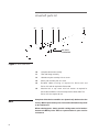
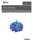
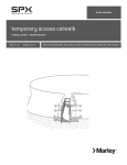
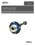
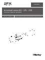
U S E R M A N UA L
driveshaft series 6Q – 175 – 250
I N S TA L L AT I O N - O P E R AT I O N - M A I N T E N A N C E
M92-1442B
I SSU E D 4/2013
R EAD AN D U N D E R STAN D TH I S MAN UAL PR IOR TO OPE RATI NG OR S E RVICI NG TH I S PROD UCT.
driveshaft parts list
1.2
1.4
1.5
1.1
1.3
BALANCE
HARDWARE
Figure 1 Series 250 shown
1.0
Complete driveshaft assembly
1.1
Tube and flange assembly
1.2Geareducer yoke assembly with set screw
Note
1.3
Motor yoke assembly with set screw
1.4
Bonded rubber bushing. 8 required for Series 6Q and
Series 175 and 16 required for Series 250.
1.5
Machine bolt or cap screw with lock washer. 8 required for
Series 6Q and Series 175 and 16 required for Series 250. The Series 175 also requires 8 nuts.
Complete driveshaft assemblies are dynamically balanced at the
factory. When replacement parts are installed, driveshaft may need
to be rebalanced.
When ordering parts, always provide cooling tower serial number.
Contact the Marley sales office or representative in your area for
assistance.
2
installation
General
Marley driveshafts consist of a motor and Geareducer yoke with rubber bushings and a tube and flange assembly. Driveshafts are balanced dynamically
and tube and yoke flanges are match-marked. See Figure 3. Do not change
position or relation of match-marked components during installation.
Driveshafts must be rebalanced whenever yokes or tube and flange
assemblies are replaced. The driveshaft may be rebalanced on the tower.
See instructions on page 6.
Installation
Before installing the driveshaft, be sure the motor and Geareducer are on level
bases and that their shafts are in reasonable alignment.
Note match numbers on the driveshaft flanges and remove the yokes. Coat the
motor shaft and Geareducer shaft with “Thred-Gard” (Crane Packing Co.) or
similar lubricant. Place the key halfway in motor and Geareducer shafts, then
install yokes as shown in Figure 4. Use a rubber mallet or wood block when
tapping yokes to prevent damage. Tighten each yoke set screw against key.
Align match numbers on tube and yoke flanges and bolt the tube and
flange assembly to the Geareducer yoke while supporting the motor end
of the tube and flange assembly. Progressively tighten bolts to 60 ft·lbƒ
(82 N·m) torque. Slide the motor so that motor yoke can be bolted to
the tube and flange assembly without pushing or pulling on the bushings. Align match numbers and bolt the motor yoke to the tube and
flange assembly. Progressively tighten bolts to 60 ft·lbƒ (82 N·m) torque.
The distance between tube and yoke flanges should be as shown in Figure 4.
Alignment
Check the alignment of motor shaft, driveshaft and Geareducer shaft by measuring between the tube and yoke flanges. Alignment requires the distance
between adjacent points on the two flanges not vary more than .005" as the
points make one complete revolution. A preliminary check of alignment can
➠
3
installation
be made by measuring between the flanges at four points: top, bottom and
two sides. Alignment requires measurement with a dial indicator as described
in the following section. A Marley Dial Indicator Alignment Kit is available
from SPX Cooling Technologies.
Checking Alignment with Marley Dial Indicator Kit
1. Screw adapter bushing into one of the balancing holes on the tube flange.
If necessary, remove any balance hardware. Reinstall balance hardware in
original location before running the drive shaft.
2. Insert the dial indicator into the adapter until indicator point contacts the
face of the yoke.
ADAPTER BUSHING
KNURLED SCREW
1/8" x 7/8" STEM
INDICATOR POINT
YOKE FACE
DIAL INDICATOR
YOKE
BALANCE HARDWARE
HOLE
Figure 2 Series 6Q shown
1 1
TUBE FLANGE
BALANCE
HARDWARE
3. The indicator point must remain in contact with the yoke face during one
complete revolution, it must not at any time be pushed in so far that it bottoms out reaching the limit of the stem movement. The total travel of the
indicator point is 0.100".
4. When the dial indicator has been positioned, tighten the knurled screw in
the adapter enough to hold the indicator stem in contact with yoke face.
5. Check alignment at each end of the driveshaft by rotating the shaft 360°
noting the total change in the reading on the dial indicator. Total indicator
reading must not exceed .005". Move the motor and/or Geareducer vertically by shimming, or horizontally by shifting on support. Align driveshaft
4
installation
until the total indicator reading at each end is within .005". Tighten all
mounting bolts on the motor and Geareducer, and recheck alignment.
Maintain gap between face of flange and face of yoke as shown in
Figure 4.
Vibration
Forced vibration is a condition where a mechanical system is caused to vibrate
at other than a natural frequency. A forced vibration can result from driveshaft
imbalance. Vibration at the driveshaft or motor shaft, rotating frequency as
measured on the motor suggests driveshaft or motor rotor imbalance. The
severity of imbalance is measured in terms of mils, or thousands of an inch,
displacement is usually read in peak-to-peak or double amplitude. For example,
a vibration at .002" peak-to-peak at 29.3 CPS (1760 RPM ÷ 60 seconds =
29.3 cycles per second) could indicate a motor rotor or driveshaft imbalance.
Note
Drive shaft vibration resulting from imbalance can generally be reduced to .002" peak-to-peak, but in no case should it exceed .005".
If vibration is considered excessive and driveshaft imbalance is suspected on
a fan-cell of a multicell tower, measure and record vibration amplitude and
frequency in horizontal and vertical planes at the motor and at the Geareducer
with all fans, except the one being tested, in operation. These readings will
show the vibration introduced from outside sources. Do not attempt to compensate for this vibration within the fan-cell under test.
Start the motor on the test cell. Measure and record vibration amplitude and
frequency at the same points and attitudes as above. Three sets of readings
should be obtained and the average compared with vibration measured as
described in the previous paragraph with the test cell not in operation. The
differences in amplitude are the vibration characteristics of the test cell.
If operating conditions permit, stop all motors on the tower except in the test
cell and measure vibration as before. This will verify test cell vibration characteristics as calculated above.
5
installation
Balancing
Note
When balancing a driveshaft on the cooling tower, do not exceed
30 seconds/hour total motor starting time. The motor may become
overheated.
Add or remove washer weight or weights on one of the 3⁄8" balancing bolts in
the driveshaft tube flange at the motor end. Figures 1 and 2. If improvement
is made, continue to add or remove more washer weights at the same point.
Note
Adding weights at one point has the same effect as removing similar
weights directly opposite (180°) . This can be used to keep the total
weights to a minimum.
If vibration increases, restore original condition and repeat the same operation
on a bolt 90° from starting point.
After the motor end is adjusted, repeat the same operation on the Geareducer
end. Recheck the motor end to determine if the Geareducer end balance
operation has increased motor end vibration reading. If so, repeat balancing
of each end until no change in the opposite end is affected.
If a satisfactory balance cannot be obtained, turn the drive shaft tube and
flange assembly end for end and repeat the balancing operation. Vibration
readings can be taken on the motor with the motor yoke installed and the
driveshaft disconnected to determine motor and yoke roughness. If vibration
readings still indicate roughness, remove the yoke from the motor shaft and
repeat the test to determine motor roughness.
Note
Marley driveshafts do not require lubrication.
Inspection of the complete driveshaft should be made at least every six (6)
months. Look for corrosion, checking or cracking of rubber bushings, looseness
of hardware, and alignment of the driveshaft. Accurate drive shaft alignment
is required to insure maximum service life. Check alignment as outlined in the
preceding section on page 4. Repair or replace drive shaft parts as necessary.
6
maintenance
Replacing Bonded Rubber Bushings
1. Remove the tube and flange assembly by removing the 5⁄8" machine bolts or
cap screws at each end of the driveshaft. It may be necessary to loosen the
motor mounting bolts and slide the motor back slightly to provide clearance
for the tube and flange assembly to be removed.
2. Remove bushings by driving or pulling out of yoke sockets in the direction
of the yoke face.
3. Clean yoke sockets but do not polish.
4. Lubricate bushing with rubber lubricant before inserting into the socket
from the yoke face.
5. Using a C-clamp, press the bushing into the socket letting the sleeve end
extend 1⁄4" ± 1⁄32" beyond the Series 6Q and Series 175 yoke face and 3⁄16"
± 1⁄32" beyond the Series 250 yoke face. Bushing bore must be perpendicular to the yoke face.
6. Care must be exercised to insure equal projection of all the bushings.
Should it be necessary to straighten the bushing in the socket, insert a
5
⁄8" bolt into the bushing and drive the bushing lightly from the side to attain perpendicularity between the bore of the bushing and the yoke face.
7. Replace the driveshaft tube and flange assembly. Be sure to match the
numbers on the tube flanges with their respective numbers on the motor
and Geareducer yokes. Install 5⁄8" machine bolts or cap screws in each end
of driveshaft. Tighten to 60 ft·lbƒ (82 N·m) torque. See Figures 3 and 4.
➠
YOKE
2
Figure 3 Series 6Q shown
2
MATCH-MARK
NUMBERS
TUBE AND FLANGE
7
driveshaft user manual
BONDED RUBBER
BUSHING
1/4" ±1/32" (SERIES 6Q AND 175)
3/16" ±1/32" (SERIES 250)
MAX. SHAFT
2 7/8"
1
ENGAGEMENT + /8" -3/8"
Figure 4 Series 250 shown
8. If the motor has been moved back to permit removal of the tube and
flange assembly, reposition the motor, being sure that flange spacing
is maintained. See Figure 4. Tighten the 5⁄8" machine bolts or cap screws to
60 ft·lbƒ (82 N·m) torque. For the Series 6Q and Series 175 driveshaft, use
an Allen wrench to prevent bushing from rotating in its socket. Recheck
driveshaft alignment and tighten motor mounting bolts.
9. Rebalance driveshaft if necessary.
S PX C O O L I N G T E C H N O LO G I E S , I N C .
7401 W 129 STREET
OVERLAND PARK, KANSAS 66213 USA
P: 913 664 7400
F: 913 664 7439
[email protected]
In the interest of technological progress, all products are subject to design
and/or material change without notice
ISSUED 04/2013 M92-1442B
COPYRIGHT ©2013 SPX Corporation