1
P L A N 4 0 0
I N S T A L L E R
G U I D E
lock outputs for the specified door will be switched for the pre-selected lock
delay time.
The RTE is generally used in the following circumstances…
•
to provide an exit signal in the case of alarmed doors.
•
to allow a means of exit for doors with no mechanical override (e.g.
Mag-locks).
•
to allow the location of a remote override button.
•
to provide an interface point between third party systems (such as
required by telephone entry systems).
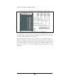
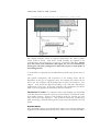
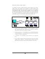
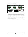
See the diagram in the ‘Readers’ section for termination details.
Door Monitoring Alarm (MC Input)
Using the MC input, the PLAN400 can monitor system for Door Forced or
Door Ajar alarms…
Door Forced: If the MC input is open circuit without there first having been a
valid card or RTE, then a Door Forced alarm will be generated.
Door Ajar: If the MC input remains open circuit for longer than the allocated
door ajar delay then a Door Ajar alarm will be generated.
To use the door monitoring feature, connect a normally closed alarm circuit
between MC and 0V (this input would usually be derived from an integrated
contact within the locking device).
See the diagram in the ‘Readers’ section for termination details.
Note: In addition to the door state monitoring for reader controlled doors,
the PLAN400 features an additional 16 extended supervised alarm inputs…
please see ‘Extended Alarms’ for connection information.
Locks
The PLAN400 provides the installer with two options for the connection of
locking devices or third party control equipment (such as vehicle barriers or
powered doors).
11