1
P L A N 4 0 0
I N S T A L L E R
G U I D E
Mounting
Remove and retain all packaging and documentation that was shipped with the
unit (including the ‘accessories’ pack on the rear of the panel enclosure). The
precise fixing methods will vary from application to application, however as a
general guide…
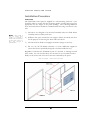
1) Use the key (contained in the accessories pack) to open the outer door
of the panel. Disconnect the earth continuity lead and remove the
outer door and set aside.
2) Remove the screws that retain the ‘inner door’. The ‘inner door’
carries the keypad and display assembly as well as the microprocessor
controller PCB. Again disconnect the earth lead and remove the
complete PCB/Inner lid assembly. Set aside in a safe location.
3) Before fitting the back-box to the wall, establish the preferred route
for cable access into the enclosure… the box is supplied with a
number of 25mm holes to the rear and several 20mm ‘knock-out’
access points to the top, bottom and side walls. Use a hammer and
punch to remove any of ‘knock-outs’ and drill any additional holes that
are required before fixing the box to the wall.
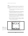
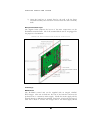
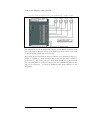
4) There are four fixing holes in the rear of the enclosure… (see diagram
below). If necessary, use the back-box as a template to mark the
fixing holes on the wall - note that the top two fixings are ‘key-holed’
to enable easier single handed installation.
P LAN400 BACK BOX
FIXINGS AND DIMESIONS
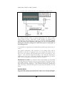
Note:-, the detachable lid
and PCB assembly are hinged
on the left hand side of the
enclosure care should be
taken to allow sufficient
clearance on the left hand
side of the unit for the outer
lid to open approx. 100
degrees.
H=370mm, W=360mm, D=140 (inclusive of door)
7