1
R&S®FSW
Network and Remote Operation
10 Network and Remote Operation
In addition to working with the R&S FSW interactively, located directly at the instrument,
it is also possible to operate and control it from a remote PC. Various methods for remote
control are supported:
●
Connecting the instrument to a (LAN) network
●
Using the LXI browser interface in a LAN network
●
Using the Windows Remote Desktop application in a LAN network
●
Connecting a PC via the GPIB interface
How to configure the remote control interfaces is described in chapter 10.5, "How to Set
Up a Network and Remote Control", on page 598.
10.1
Remote Control Basics.............................................................................................554
10.1.1
Remote Control Interfaces and Protocols...................................................................554
10.1.2
SCPI (Standard Commands for Programmable Instruments).....................................558
10.1.3
VISA Libraries.............................................................................................................558
10.1.4
Messages....................................................................................................................559
10.1.5
SCPI Command Structure...........................................................................................560
10.1.6
Command Sequence and Synchronization.................................................................568
10.1.7
Status Reporting System............................................................................................570
10.1.8
General Programming Recommendations..................................................................586
10.2
GPIB Languages.......................................................................................................587
10.3
The IECWIN Tool.......................................................................................................589
10.4
Network and Remote Control Settings...................................................................590
10.4.1
General Network Settings...........................................................................................590
10.4.2
GPIB Settings..............................................................................................................592
10.4.3
Compatibility Settings..................................................................................................594
10.4.4
LXI Settings.................................................................................................................597
10.5
How to Set Up a Network and Remote Control......................................................598
10.5.1
How to Configure a Network.......................................................................................599
10.5.2
How to Operate the Instrument Without a Network.....................................................605
10.5.3
How to Log on to the Network.....................................................................................605
10.5.4
How to Share Directories (only with Microsoft Networks)...........................................607
10.5.5
How to Set Up Remote Desktop.................................................................................608
10.5.6
How to Start a Remote Control Session from a PC....................................................615
10.5.7
How to Return to Manual Operation............................................................................616
User Manual 1173.9411.02 ─ 13
553
R&S®FSW
Network and Remote Operation
Remote Control Basics
10.1 Remote Control Basics
Basic information on operating an instrument via remote control is provided here. this
information applies to all applications and operating modes on the R&S FSW.
10.1.1 Remote Control Interfaces and Protocols
The instrument supports different interfaces for remote control. The following table gives
an overview.
Table 10-1: Remote control interfaces and protocols
Interface
Protocols, VISA*) address string
Remarks
Local Area
Network
(LAN)
Protocols:
A LAN connector is located on the rear
panel of the instrument.
VXI-11, HiSLIP
VISA*) address string:
TCPIP::host_address[::LAN_device_name][::INSTR]
The interface is based on TCP/IP and
supports various protocols.
Raw socket
For a description of the protocols refer
to:
VISA*) address string:
VXI-11 Protocol
TCPIP::host_address::port::SOCKET
HiSLIP Protocol
Socket Communication
GPIB (IEC/
IEEE Bus
Interface)
VISA*) address string:
GPIB::primary address[::INSTR]
(no secondary address)
A GPIB bus interface (option
R&S FSW-B10) according to the IEC
625.1/IEEE 488.1 standard is located
on the rear panel of the instrument.
For a description of the interface refer
to 10.1.1.2 GPIB Interface (IEC 625/
IEEE 418 Bus Interface).
USB
VISA*) address string:
USB::<vendor ID>::<product_ID>::<serial_number>[::INSTR]
USB connectors are located on the rear
panel of the instrument.
For a description of the interface refer
to 10.1.1.3 USB Interface.
*)
VISA is a standardized software interface library providing input and output functions to communicate with instruments. A VISA
installation on the controller is a prerequisite for remote control using the indicated interfaces (see also chapter 10.1.3, "VISA Libraries", on page 558).
Within this interface description, the term GPIB is used as a synonym for the IEC/IEEE
bus interface.
10.1.1.1
LAN Interface
To be integrated in a LAN, the instrument is equipped with a LAN interface, consisting of
a connector, a network interface card and protocols. The network card can be operated
with the following interfaces:
●
10 Mbit/s Ethernet IEEE 802.3
User Manual 1173.9411.02 ─ 13
554
R&S®FSW
Network and Remote Operation
Remote Control Basics
●
100 Mbit/s Ethernet IEEE 802.3u
●
1Gbit/s Ethernet IEEE 802.3ab
For remote control via a network, the PC and the instrument must be connected via the
LAN interface to a common network with TCP/IP network protocol. They are connected
using a commercial RJ45 cable (shielded or unshielded twisted pair category 5). The
TCP/IP network protocol and the associated network services are preconfigured on the
instrument. Software for instrument control and the VISA program library must be installed on the controller.
VISA library
Instrument access is usually achieved from high level programming platforms using VISA
as an intermediate abstraction layer. VISA encapsulates the low level VXI, GPIB, LAN or
USB function calls and thus makes the transport interface transparent for the user. See
chapter 10.1.3, "VISA Libraries", on page 558 for details.
The R&S FSW supports various LAN protocols such as LXI, RSIB, raw socket or the
newer HiSLIP protocol.
IP address
Only the IP address or a valid DNS host name is required to set up the connection. The
host address is part of the "VISA resource string" used by the programs to identify and
control the instrument.
The VISA resource string has the form:
TCPIP::host address[::LAN device name][::INSTR]
or
TCPIP::host address::port::SOCKET
where:
●
TCPIP designates the network protocol used
●
host address is the IP address or host name of the device
●
LAN device name defines the protocol and the instance number of a sub-instrument;
– inst0 selects the VXI-11 protocol (default)
–
hislip0 selects the newer HiSLIP protocol
●
INSTR indicates the instrument resource class (optional)
●
port determines the used port number
●
SOCKET indicates the raw network socket resource class
User Manual 1173.9411.02 ─ 13
555
R&S®FSW
Network and Remote Operation
Remote Control Basics
Example:
●
Instrument has the IP address 192.1.2.3; the valid resource string using VXI-11 protocol is:
TCPIP::192.1.2.3::INSTR
●
The DNS host name name is FSW-123456; the valid resource string using HiSLIP
is:
TCPIP::FSW-123456::hislip0
●
A raw socket connection can be established using:
TCPIP::192.1.2.3::5025::SOCKET
Identifying instruments in a network
If several instruments are connected to the network, each instrument has its own IP
address and associated resource string. The controller identifies these instruments by
means of the resource string.
For details on configuring the LAN connection, see chapter 10.5.1, "How to Configure a
Network", on page 599.
VXI-11 Protocol
The VXI-11 standard is based on the ONC RPC (Open Network Computing Remote
Procedure Call) protocol which in turn relies on TCP/IP as the network/transport layer.
The TCP/IP network protocol and the associated network services are preconfigured.
TCP/IP ensures connection-oriented communication, where the order of the exchanged
messages is adhered to and interrupted links are identified. With this protocol, messages
cannot be lost.
HiSLIP Protocol
The HiSLIP (High Speed LAN Instrument Protocol) is the successor protocol for VXI-11
for TCP-based instruments specified by the IVI foundation. The protocol uses two TCP
sockets for a single connection - one for fast data transfer, the other for non-sequential
control commands (e.g. Device Clear or SRQ).
HiSLIP has the following characteristics:
●
High performance as with raw socket network connections
●
Compatible IEEE 488.2 support for Message Exchange Protocol, Device Clear,
Serial Poll, Remote/Local, Trigger, and Service Request
●
Uses a single IANA registered port (4880), which simplifies the configuration of firewalls
●
Supports simultaneous access of multiple users by providing versatile locking mechanisms
●
Usable for IPv6 or IPv4 networks
User Manual 1173.9411.02 ─ 13
556
R&S®FSW
Network and Remote Operation
Remote Control Basics
Note that HiSLIP data is sent to the device using the "fire and forget" method with immediate return, as opposed to VXI-11, where each operation is blocked until a VXI-11 device
handshake returns. Thus, a successful return of a VISA operation such as viWrite()
does not guarantee that the instrument has finished or started the requested command,
but is delivered to the TCP/IP buffers.
For more information see also the application note at: http://www.rohde-schwarz.com/
appnote/1MA208.
Socket Communication
An alternative way for remote control of the software is to establish a simple network
communication using sockets. The socket communication, also referred to as "Raw
Ethernet communication", does not necessarily require a VISA installation on the remote
controller side. It is available by default on all operating systems.
The simplest way to establish socket communication is to use the built-in telnet program.
The telnet program is part of every operating system and supports a communication with
the software on a command-by-command basis. For more convenience and to enable
automation by means of programs, user-defined sockets can be programmed.
Socket connections are established on a specially defined port. The socket address is a
combination of the IP address or the host name of the instrument and the number of the
port configured for remote-control. All Signal and Spectrum Analyzers use port number
5025 for this purpose. The port is configured for communication on a command-to-command basis and for remote control from a program.
10.1.1.2
GPIB Interface (IEC 625/IEEE 418 Bus Interface)
A GPIB interface is integrated on the rear panel of the instrument. By connecting a PC
to the R&S FSW via the GPIB connection you can send remote commands to control and
operate the instrument.
To be able to control the instrument via the GPIB bus, the instrument and the controller
must be linked by a GPIB bus cable. A GPIB bus card, the card drivers and the program
libraries for the programming language used must be provided in the controller. The controller must address the instrument with the GPIB bus address (see chapter 10.5.1.5,
"How to Change the GPIB Instrument Address", on page 605). You can set the GPIB
address and the ID response string. The GPIB language is set as SCPI by default and
cannot be changed for the R&S FSW.
Notes and Conditions
In connection with the GPIB interface, note the following:
●
Up to 15 instruments can be connected
●
The total cable length is restricted to a maximum of 15 m or 2 m times the number of
devices, whichever is less; the cable lenth between two instruments should not
exceed 2 m.
●
A wired "OR"-connection is used if several instruments are connected in parallel.
User Manual 1173.9411.02 ─ 13
557
R&S®FSW
Network and Remote Operation
Remote Control Basics
●
10.1.1.3
Any connected IEC-bus cables should be terminated by an instrument or controller.
USB Interface
For remote control via the USB connection, the PC and the instrument must be connected
via the USB type B interface. A USB connection requires the VISA library to be installed.
VISA detects and configures the R&S instrument automatically when the USB connection
is established. You do not have to enter an address string or install a separate driver.
USB address
The used USB address string is:
USB::<vendor ID>::<product ID>::<serial number>[::INSTR]
where:
●
<vendor ID> is the vendor ID for Rohde&Schwarz
●
<product ID> is the product ID for the R&S instrument
●
<serial number> is the individual serial number on the rear of the instrument
Example:
USB::0x0AAD::0x00C6::100001::INSTR
0x0AAD is the vendor ID for Rohde&Schwarz
0xC6 is the product ID for the R&S FSW13
100001 is the serial number of the particular instrument
10.1.2 SCPI (Standard Commands for Programmable Instruments)
SCPI commands - messages - are used for remote control. Commands that are not taken
from the SCPI standard follow the SCPI syntax rules. The instrument supports the SCPI
version 1999. The SCPI standard is based on standard IEEE 488.2 and aims at the
standardization of device-specific commands, error handling and the status registers.
The tutorial "Automatic Measurement Control - A tutorial on SCPI and IEEE 488.2" from
John M. Pieper (R&S order number 0002.3536.00) offers detailed information on concepts and definitions of SCPI.
Tables provide a fast overview of the bit assignment in the status registers. The tables
are supplemented by a comprehensive description of the status registers.
10.1.3 VISA Libraries
VISA is a standardized software interface library providing input and output functions to
communicate with instruments. The I/O channel (LAN or TCP/IP, USB, GPIB,...) is
selected at initialization time by means of the channel–specific address string ("VISA
resource string") indicated in table 10-1, or by an appropriately defined VISA alias (short
name).
A VISA installation is a prerequisite for remote control using the following interfaces:
User Manual 1173.9411.02 ─ 13
558
R&S®FSW
Network and Remote Operation
Remote Control Basics
●
chapter 10.1.1.1, "LAN Interface", on page 554
●
chapter 10.1.1.2, "GPIB Interface (IEC 625/IEEE 418 Bus Interface)", on page 557
●
chapter 10.1.1.3, "USB Interface", on page 558
For more information about VISA refer to the user documentation.
10.1.4 Messages
The messages transferred on the data lines are divided into the following categories:
●
Interface messages
Interface messages are transmitted to the instrument on the data lines, with the
attention line being active (LOW). They are used to communicate between the controller and the instrument. Interface messages can only be sent by instruments that
have GPIB bus functionality. For details see the sections for the required interface.
●
Instrument messages
Instrument messages are employed in the same way for all interfaces, if not indicated
otherwise in the description. Structure and syntax of the instrument messages are
described in chapter 10.1.5, "SCPI Command Structure", on page 560. A detailed
description of all messages available for the instrument is provided in the chapter
"Remote Control Commands".
There are different types of instrument messages, depending on the direction they
are sent:
– Commands
–
Instrument responses
Commands
Commands (program messages) are messages the controller sends to the instrument.
They operate the instrument functions and request information. The commands are subdivided according to two criteria:
●
According to the effect they have on the instrument:
– Setting commands cause instrument settings such as a reset of the instrument
or setting the frequency.
–
●
Queries cause data to be provided for remote control, e.g. for identification of the
instrument or polling a parameter value. Queries are formed by directly appending
a question mark to the command header.
According to their definition in standards:
– Common commands: their function and syntax are precisely defined in standard
IEEE 488.2. They are employed identically on all instruments (if implemented).
They refer to functions such as management of the standardized status registers,
reset and self test.
–
Instrument control commands refer to functions depending on the features of
the instrument such as frequency settings. Many of these commands have also
been standardized by the SCPI committee. These commands are marked as
"SCPI confirmed" in the command reference chapters. Commands without this
SCPI label are device-specific; however, their syntax follows SCPI rules as permitted by the standard.
User Manual 1173.9411.02 ─ 13
559
R&S®FSW
Network and Remote Operation
Remote Control Basics
Instrument responses
Instrument responses (response messages and service requests) are messages the
instrument sends to the controller after a query. They can contain measurement results,
instrument settings and information on the instrument status.
10.1.5 SCPI Command Structure
SCPI commands consist of a so-called header and, in most cases, one or more parameters. The header and the parameters are separated by a "white space" (ASCII code 0
to 9, 11 to 32 decimal, e.g. blank). The headers may consist of several mnemonics (keywords). Queries are formed by appending a question mark directly to the header.
The commands can be either device-specific or device-independent (common commands). Common and device-specific commands differ in their syntax.
10.1.5.1
Syntax for Common Commands
Common (=device-independent) commands consist of a header preceded by an asterisk
(*) and possibly one or more parameters.
Examples:
*RST
RESET
Resets the instrument.
*ESE
EVENT STATUS ENABLE
Sets the bits of the event status enable
registers.
*ESR?
EVENT STATUS QUERY
Queries the contents of the event status
register.
*IDN?
IDENTIFICATION QUERY
Queries the instrument identification
string.
User Manual 1173.9411.02 ─ 13
560
R&S®FSW
Network and Remote Operation
Remote Control Basics
10.1.5.2
Syntax for Device-Specific Commands
Not all commands used in the following examples are necessarily implemented in the
instrument.
For demonstration purposes only, assume the existence of the following commands for
this section:
●
DISPlay[:WINDow<1...4>]:MAXimize <Boolean>
●
FORMat:READings:DATA <type>[,<length>]
●
HCOPy:DEVice:COLor <Boolean>
●
HCOPy:DEVice:CMAP:COLor:RGB <red>,<green>,<blue>
●
HCOPy[:IMMediate]
●
HCOPy:ITEM:ALL
●
HCOPy:ITEM:LABel <string>
●
HCOPy:PAGE:DIMensions:QUADrant[<N>]
●
HCOPy:PAGE:ORIentation LANDscape | PORTrait
●
HCOPy:PAGE:SCALe <numeric value>
●
MMEMory:COPY <file_source>,<file_destination>
●
SENSE:BANDwidth|BWIDth[:RESolution] <numeric_value>
●
SENSe:FREQuency:STOP <numeric value>
●
SENSe:LIST:FREQuency <numeric_value>{,<numeric_value>}
Long and short form
The mnemonics feature a long form and a short form. The short form is marked by upper
case letters, the long form corresponds to the complete word. Either the short form or the
long form can be entered; other abbreviations are not permitted.
Example:
HCOPy:DEVice:COLor ON is equivalent to HCOP:DEV:COL ON.
Case-insensitivity
Upper case and lower case notation only serves to distinguish the two forms in the manual, the instrument itself is case-insensitive.
Numeric suffixes
If a command can be applied to multiple instances of an object, e.g. specific channels or
sources, the required instances can be specified by a suffix added to the command.
Numeric suffixes are indicated by angular brackets (<1...4>, <n>, <i>) and are replaced
by a single value in the command. Entries without a suffix are interpreted as having the
suffix 1.
User Manual 1173.9411.02 ─ 13
561
R&S®FSW
Network and Remote Operation
Remote Control Basics
Example:
Definition: HCOPy:PAGE:DIMensions:QUADrant[<N>]
Command: HCOP:PAGE:DIM:QUAD2
This command refers to the quadrant 2.
Different numbering in remote control
For remote control, the suffix may differ from the number of the corresponding selection
used in manual operation. SCPI prescribes that suffix counting starts with 1. Suffix 1 is
the default state and used when no specific suffix is specified.
Some standards define a fixed numbering, starting with 0. If the numbering differs in
manual operation and remote control, it is indicated for the corresponding command.
Optional mnemonics
Some command systems permit certain mnemonics to be inserted into the header or
omitted. These mnemonics are marked by square brackets in the description. The instrument must recognize the long command to comply with the SCPI standard. Some commands are considerably shortened by these optional mnemonics.
Example:
Definition: HCOPy[:IMMediate]
Command: HCOP:IMM is equivalent to HCOP
Optional mnemonics with numeric suffixes
Do not omit an optional mnemonic if it includes a numeric suffix that is relevant for the
effect of the command.
Example:
Definition:DISPlay[:WINDow<1...4>]:MAXimize <Boolean>
Command: DISP:MAX ON refers to window 1.
In order to refer to a window other than 1, you must include the optional WINDow parameter with the suffix for the required window.
DISP:WIND2:MAX ON refers to window 2.
Parameters
Parameters must be separated from the header by a "white space". If several parameters
are specified in a command, they are separated by a comma (,). For a description of the
parameter types, refer to chapter 10.1.5.3, "SCPI Parameters", on page 563.
Example:
Definition:HCOPy:DEVice:CMAP:COLor:RGB <red>,<green>,<blue>
Command:HCOP:DEV:CMAP:COL:RGB 3,32,44
User Manual 1173.9411.02 ─ 13
562
R&S®FSW
Network and Remote Operation
Remote Control Basics
Special characters
|
Parameters
A vertical stroke in parameter definitions indicates alternative possibilities in the sense of "or". The effect
of the command differs, depending on which parameter is used.
Example:
Definition:HCOPy:PAGE:ORIentation LANDscape | PORTrait
Command HCOP:PAGE:ORI LAND specifies landscape orientation
Command HCOP:PAGE:ORI PORT specifies portrait orientation
Mnemonics
A selection of mnemonics with an identical effect exists for several commands. These mnemonics are
indicated in the same line; they are separated by a vertical stroke. Only one of these mnemonics needs
to be included in the header of the command. The effect of the command is independent of which of the
mnemonics is used.
Example:
DefinitionSENSE:BANDwidth|BWIDth[:RESolution] <numeric_value>
The two following commands with identical meaning can be created:
SENS:BAND:RES 1
SENS:BWID:RES 1
[]
Mnemonics in square brackets are optional and may be inserted into the header or omitted.
Example: HCOPy[:IMMediate]
HCOP:IMM is equivalent to HCOP
{}
Parameters in curly brackets are optional and can be inserted once or several times, or omitted.
Example: SENSe:LIST:FREQuency <numeric_value>{,<numeric_value>}
The following are valid commands:
SENS:LIST:FREQ 10
SENS:LIST:FREQ 10,20
SENS:LIST:FREQ 10,20,30,40
10.1.5.3
SCPI Parameters
Many commands are supplemented by a parameter or a list of parameters. The parameters must be separated from the header by a "white space" (ASCII code 0 to 9, 11 to 32
decimal, e.g. blank). Allowed parameters are:
●
Numeric values
●
Special numeric values
●
Boolean parameters
●
Text
●
Character strings
●
Block data
The parameters required for each command and the allowed range of values are specified in the command description.
User Manual 1173.9411.02 ─ 13
563
R&S®FSW
Network and Remote Operation
Remote Control Basics
Numeric values
Numeric values can be entered in any form, i.e. with sign, decimal point and exponent.
Values exceeding the resolution of the instrument are rounded up or down. The mantissa
may comprise up to 255 characters, the exponent must lie inside the value range -32000
to 32000. The exponent is introduced by an "E" or "e". Entry of the exponent alone is not
allowed. In the case of physical quantities, the unit can be entered. Allowed unit prefixes
are G (giga), MA (mega), MOHM and MHZ are also allowed), K (kilo), M (milli), U (micro)
and N (nano). If the unit is missing, the basic unit is used.
Example: SENS:FREQ:STOP 1.5GHz = SENS:FREQ:STOP 1.5E9
Units
For physical quantities, the unit can be entered. Allowed unit prefixes are:
●
G (giga)
●
MA (mega), MOHM, MHZ
●
K (kilo)
●
M (milli)
●
U (micro)
●
N (nano)
If the unit is missing, the basic unit is used.
Example:
SENSe:FREQ:STOP 1.5GHz = SENSe:FREQ:STOP 1.5E9
Some settings allow relative values to be stated in percent. According to SCPI, this unit
is represented by the PCT string.
Example:
HCOP:PAGE:SCAL 90PCT
Special numeric values
The texts listed below are interpreted as special numeric values. In the case of a query,
the numeric value is provided.
●
MIN/MAX
MINimum and MAXimum denote the minimum and maximum value.
●
DEF
DEFault denotes a preset value which has been stored in the EPROM. This value
conforms to the default setting, as it is called by the *RST command.
●
UP/DOWN
UP, DOWN increases or reduces the numeric value by one step. The step width can
be specified via an allocated step command for each parameter which can be set via
UP, DOWN.
●
INF/NINF
User Manual 1173.9411.02 ─ 13
564
R&S®FSW
Network and Remote Operation
Remote Control Basics
INFinity, Negative INFinity (NINF) represent the numeric values 9.9E37 or -9.9E37,
respectively. INF and NINF are only sent as instrument responses.
●
NAN
Not A Number (NAN) represents the value 9.91E37. NAN is only sent as a instrument
response. This value is not defined. Possible causes are the division of zero by zero,
the subtraction of infinite from infinite and the representation of missing values.
Example:
Setting command: SENSe:LIST:FREQ MAXimum
Query: SENS:LIST:FREQ?, Response: 3.5E9
Queries for special numeric values
The numeric values associated to MAXimum/MINimum/DEFault can be queried by
adding the corresponding mnemonics to the command. They must be entered following
the quotation mark.
Example: SENSe:LIST:FREQ? MAXimum
Returns the maximum numeric value as a result.
Boolean Parameters
Boolean parameters represent two states. The "ON" state (logically true) is represented
by "ON" or a numeric value 1. The "OFF" state (logically untrue) is represented by
"OFF" or the numeric value 0. The numeric values are provided as the response for a
query.
Example:
Setting command: HCOPy:DEV:COL ON
Query: HCOPy:DEV:COL?
Response: 1
Text parameters
Text parameters observe the syntactic rules for mnemonics, i.e. they can be entered
using a short or long form. Like any parameter, they have to be separated from the header
by a white space. In the case of a query, the short form of the text is provided.
Example:
Setting command: HCOPy:PAGE:ORIentation LANDscape
Query: HCOP:PAGE:ORI?
Response: LAND
Character strings
Strings must always be entered in quotation marks (' or ").
User Manual 1173.9411.02 ─ 13
565
R&S®FSW
Network and Remote Operation
Remote Control Basics
Example:
HCOP:ITEM:LABel "Test1" or HCOP:ITEM:LABel 'Test1'
Block data
Block data is a format which is suitable for the transmission of large amounts of data. A
command using a block data parameter has the following structure:
Example:
FORMat:READings:DATA
#45168xxxxxxxx
The ASCII character # introduces the data block. The next number indicates how many
of the following digits describe the length of the data block. In the example the 4 following
digits indicate the length to be 5168 bytes. The data bytes follow. During the transmission
of these data bytes all end or other control signs are ignored until all bytes are transmitted.
#0 specifies a data block of indefinite length. The use of the indefinite format requires a
NL^END message to terminate the data block. This format is useful when the length of
the transmission is not known or if speed or other considerations prevent segmentation
of the data into blocks of definite length.
10.1.5.4
Overview of Syntax Elements
The following table provides an overview of the syntax elements:
:
The colon separates the mnemonics of a command. In a command line the separating semicolon
marks the uppermost command level.
;
The semicolon separates two commands of a command line. It does not alter the path.
,
The comma separates several parameters of a command.
?
The question mark forms a query.
*
The asterisk marks a common command.
''
Quotation marks introduce a string and terminate it (both single and double quotation marks are
possible).
"
#
The hash symbol introduces binary, octal, hexadecimal and block data.
Binary: #B10110
●
Octal: #O7612
●
Hexa: #HF3A7
●
Block: #21312
●
A "white space" (ASCII-Code 0 to 9, 11 to 32 decimal, e.g. blank) separates the header from the
parameters.
10.1.5.5
Structure of a command line
A command line may consist of one or several commands. It is terminated by one of the
following:
●
a <New Line>
User Manual 1173.9411.02 ─ 13
566
R&S®FSW
Network and Remote Operation
Remote Control Basics
●
a <New Line> with EOI
●
an EOI together with the last data byte
Several commands in a command line must be separated by a semicolon ";". If the next
command belongs to a different command system, the semicolon is followed by a colon.
Example:
MMEM:COPY "Test1","MeasurementXY";:HCOP:ITEM ALL
This command line contains two commands. The first command belongs to the MMEM
system, the second command belongs to the HCOP system.
If the successive commands belong to the same system, having one or several levels in
common, the command line can be abbreviated. To this end, the second command after
the semicolon starts with the level that lies below the common levels. The colon following
the semicolon must be omitted in this case.
Example:
HCOP:ITEM ALL;:HCOP:IMM
This command line contains two commands. Both commands are part of the HCOP command system, i.e. they have one level in common.
When abbreviating the command line, the second command begins with the level below
HCOP. The colon after the semicolon is omitted. The abbreviated form of the command
line reads as follows:
HCOP:ITEM ALL;IMM
A new command line always begins with the complete path.
Example:
HCOP:ITEM ALL
HCOP:IMM
10.1.5.6
Responses to Queries
A query is defined for each setting command unless explicitly specified otherwise. It is
formed by adding a question mark to the associated setting command. According to
SCPI, the responses to queries are partly subject to stricter rules than in standard IEEE
488.2.
●
The requested parameter is transmitted without a header.
Example: HCOP:PAGE:ORI?, Response: LAND
●
Maximum values, minimum values and all other quantities that are requested via a
special text parameter are returned as numeric values.
Example: SENSe:FREQuency:STOP? MAX, Response: 3.5E9
●
Numeric values are output without a unit. Physical quantities are referred to the basic
units or to the units set using the Unit command. The response 3.5E9 in the previous example stands for 3.5 GHz.
●
Truth values (Boolean values) are returned as 0 (for OFF) and 1 (for ON).
User Manual 1173.9411.02 ─ 13
567
R&S®FSW
Network and Remote Operation
Remote Control Basics
Example:
Setting command: HCOPy:DEV:COL ON
Query: HCOPy:DEV:COL?
Response: 1
●
Text (character data) is returned in a short form.
Example:
Setting command: HCOPy:PAGE:ORIentation LANDscape
Query: HCOP:PAGE:ORI?
Response: LAND
10.1.6 Command Sequence and Synchronization
IEEE 488.2 defines a distinction between overlapped and sequential commands:
●
A sequential command is one which finishes executing before the next command
starts executing. Commands that are processed quickly are usually implemented as
sequential commands.
●
An overlapping command is one which does not automatically finish executing before
the next command starts executing. Usually, overlapping commands take longer to
process and allow the program to do other tasks while being executed. If overlapping
commands do have to be executed in a defined order, e.g. in order to avoid wrong
measurement results, they must be serviced sequentially. This is called synchronization between the controller and the instrument.
Setting commands within one command line, even though they may be implemented as
sequential commands, are not necessarily serviced in the order in which they have been
received. In order to make sure that commands are actually carried out in a certain order,
each command must be sent in a separate command line.
Example: Commands and queries in one message
The response to a query combined in a program message with commands that affect the
queried value is not predictable.
The following commands always return the specified result:
:FREQ:STAR 1GHZ;SPAN 100;:FREQ:STAR?
Result:
1000000000 (1 GHz)
Whereas the result for the following commands is not specified by SCPI:
:FREQ:STAR 1GHz;STAR?;SPAN 1000000
The result could be the value of STARt before the command was sent since the instrument might defer executing the individual commands until a program message terminator
is received. The result could also be 1 GHz if the instrument executes commands as they
are received.
As a general rule, send commands and queries in different program messages.
User Manual 1173.9411.02 ─ 13
568
R&S®FSW
Network and Remote Operation
Remote Control Basics
Example: Overlapping command with *OPC
The instrument implements INITiate[:IMMediate] as an overlapped command.
Assuming that INITiate[:IMMediate] takes longer to execute than *OPC, sending
the following command sequence results in initiating a sweep and, after some time, setting the OPC bit in the ESR:
INIT; *OPC.
Sending the following commands still initiates a sweep:
INIT; *OPC; *CLS
However, since the operation is still pending when the instrument executes *CLS, forcing
it into the "Operation Complete Command Idle" State (OCIS), *OPC is effectively skipped.
The OPC bit is not set until the instrument executes another *OPC command.
10.1.6.1
Preventing Overlapping Execution
To prevent an overlapping execution of commands, one of the commands *OPC, *OPC?
or *WAI can be used. All three commands cause a certain action only to be carried out
after the hardware has been set. By suitable programming, the controller can be forced
to wait for the corresponding action to occur.
Table 10-2: Synchronization using *OPC, *OPC? and *WAI
Command
Action
Programming the controller
*OPC
Sets the Operation Complete bit in the ESR
●
after all previous commands have been execu- ●
●
ted.
*OPC?
Stops command processing until 1 is returned. Sending *OPC? directly after the command
This is only the case after the Operation Com- whose processing should be terminated before
plete bit has been set in the ESR. This bit indi- other commands can be executed.
cates that the previous setting has been completed.
*WAI
Stops further command processing until all
commands sent before *WAI have been executed.
Setting bit 0 in the ESE
Setting bit 5 in the SRE
Waiting for service request (SRQ)
Sending *WAI directly after the command
whose processing should be terminated before
other commands are executed.
Command synchronization using *WAI or *OPC? appended to an overlapped command
is a good choice if the overlapped command takes only little time to process. The two
synchronization techniques simply block overlapped execution of the command.
For time consuming overlapped commands it is usually desirable to allow the controller
or the instrument to do other useful work while waiting for command execution. Use one
of the following methods:
*OPC with a service request
1. Set the OPC mask bit (bit no. 0) in the ESE: *ESE 1
2. Set bit no. 5 in the SRE: *SRE 32 to enable ESB service request.
3. Send the overlapped command with *OPC
User Manual 1173.9411.02 ─ 13
569
R&S®FSW
Network and Remote Operation
Remote Control Basics
4. Wait for a service request
The service request indicates that the overlapped command has finished.
*OPC? with a service request
1. Set bit no. 4 in the SRE: *SRE 16 to enable MAV service request.
2. Send the overlapped command with *OPC?
3. Wait for a service request
The service request indicates that the overlapped command has finished.
Event Status Register (ESE)
1. Set the OPC mask bit (bit no. 0) in the ESE: *ESE 1
2. Send the overlapped command without *OPC, *OPC? or *WAI
3. Poll the operation complete state periodically (by means of a timer) using the
sequence: *OPC; *ESR?
A return value (LSB) of 1 indicates that the overlapped command has finished.
*OPC? with short timeout
1. Send the overlapped command without *OPC, *OPC? or *WAI
2. Poll the operation complete state periodically (by means of a timer) using the
sequence: <short timeout>; *OPC?
3. A return value (LSB) of 1 indicates that the overlapped command has finished. In
case of a timeout, the operation is ongoing.
4. Reset timeout to former value
5. Clear the error queue with SYStem:ERRor? to remove the "-410, Query interrupted"
entries.
Using several threads in the controller application
As an alternative, provided the programming environment of the controller application
supports threads, separate threads can be used for the application GUI and for controlling
the instrument(s) via SCPI.
A thread waiting for a *OPC? thus will not block the GUI or the communication with other
instruments.
10.1.7 Status Reporting System
The status reporting system stores all information on the current operating state of the
instrument, and on errors which have occurred. This information is stored in the status
registers and in the error queue. Both can be queried via GPIB bus or LAN interface
(STATus... commands, see chapter 11.11, "Using the Status Register", on page 956).
User Manual 1173.9411.02 ─ 13
570
R&S®FSW
Network and Remote Operation
Remote Control Basics
10.1.7.1
Hierarchy of Status Registers
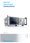
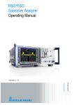
As shown in the following figure, the status information is of hierarchical structure.
&
logic AND
logic OR
*)
15
of all bits
one register for
each channel
SRQ
not used
15
not used
15
14
14
13
13
13
13
12
12
12
12
11
11
11
11
10
Range completed
10
10
10
9
MSRA Capture Finish
9
9
9
8
HCOPy in progress
8
8
8
7
7
CACLR FAIL
7
LMARgin 8 FAIL
7
LIMit 8 FAIL
6
6
ALT3...11 LOWer/UPPer FAIL
6
LMARgin 7 FAIL
6
LIMit 7 FAIL
5
Waiting for TRIGger
5
ALT2 LOWer FAIL
5
LMARgin 6 FAIL
5
LIMit 6 FAIL
4
MEASuring
4
ALT2 UPPer FAIL
4
LMARgin 5 FAIL
4
LIMit 5 FAIL
3
SWEeping
3
ALT1 LOWer FAIL
3
LMARgin 4 FAIL
3
LIMit 4 FAIL
2
2
ALT1 UPPer FAIL
2
LMARgin 3 FAIL
2
LIMit 3 FAIL
1
1
ADJ LOWer FAIL
1
LMARgin 2 FAIL
1
LIMit 2 FAIL
0
ADJ UPPer FAIL
0
LMARgin 1 FAIL
0
CALibrating
STATus:OPERation
STAT:QUES:ACPLimit *)
STAT:QUES:LMARgin<n> *)
LIMit 1 FAIL
STAT:QUES:LIMit<n> *)
7
6
RQS/MSS
&
5
ESB
&
4
MAV
&
3
15
not used
&
2
14
DIQ
1
13
0
12
SRE
not used
15
14
0
&
not used
14
15
15
STB
ACPLimit
SYNC
10
LMARGin
9
LIMit
8
&
7
&
6
&
5
&
4
TEMPerature
&
3
POWer
&
2
TIME
...
9
9
7
7
6
6
6
5
5
5
4
4
4
3
3
2
2
FREQuency
8
8
External REFerence
7
CALibration (=UNCAL)
not used
...
...
9
8
11
not used
15
not used
1
LO UNLocked
0
OVEN COLD
1
3
INPut_overload
2
IF_OVerload
1
UNDerload
0
0
Frontend temp. error
OVERload
STAT:QUES:POWer *)
STAT:QUES:TEMPerature *)
STAT:QUES:FREQuency *)
1
0
PPE
EXTended
STATus:QUEStionable
ISTflag
&
7 Power On
&
6 User Request
&
5 Command Error
&
&
4 Execution Error
Device Dependent
3
Error
2 Query Error
&
1
&
Error/ Event Output
Queue
Buffer
&
ESE
15 not used
15 not used
...
...
...
5
5
5
4
4
4
FATal
3
3
3
ERRor
2
2
2
WARNing
1
INFO
0
MESSage
15
1
not used
Sweep time too low
1
INFO
0
0
STAT:QUES:TIME *)
STAT:QUES:EXTended *)
STAT:QUES:EXTended:INFO *)
0 Operation Complete
ESR
Fig. 10-1: Graphical overview of the R&S FSW status registers hierarchy
●
STB, SRE
The STatus Byte (STB) register and its associated mask register Service Request
Enable (SRE) form the highest level of the status reporting system. The STB provides
a rough overview of the instrument status, collecting the information of the lower-level
registers.
●
ESR, SCPI registers
The STB receives its information from the following registers:
User Manual 1173.9411.02 ─ 13
571
R&S®FSW
Network and Remote Operation
Remote Control Basics
–
The Event Status Register (ESR) with the associated mask register standard
Event Status Enable (ESE).
–
The STATus:OPERation and STATus:QUEStionable registers which are
defined by SCPI and contain detailed information on the instrument.
●
IST, PPE
The IST flag ("Individual STatus"), like the SRQ, combines the entire instrument status
in a single bit. The PPE fulfills the same function for the IST flag as the SRE for the
service request.
●
Output buffer
The output buffer contains the messages the instrument returns to the controller. It
is not part of the status reporting system but determines the value of the MAV bit in
the STB and thus is represented in the overview.
All status registers have the same internal structure.
SRE, ESE
The service request enable register SRE can be used as ENABle part of the STB if the
STB is structured according to SCPI. By analogy, the ESE can be used as the ENABle
part of the ESR.
10.1.7.2
Structure of a SCPI Status Register
Each standard SCPI register consists of 5 parts. Each part has a width of 16 bits and has
different functions. The individual bits are independent of each other, i.e. each hardware
status is assigned a bit number which is valid for all five parts. Bit 15 (the most significant
bit) is set to zero for all parts. Thus the contents of the register parts can be processed
by the controller as positive integers.
Fig. 10-2: The status-register model
Description of the five status register parts
The five parts of a SCPI register have different properties and functions:
User Manual 1173.9411.02 ─ 13
572
R&S®FSW
Network and Remote Operation
Remote Control Basics
●
CONDition
The CONDition part is written into directly by the hardware or the sum bit of the next
lower register. Its contents reflect the current instrument status. This register part can
only be read, but not written into or cleared. Its contents are not affected by reading.
●
PTRansition / NTRansition
The two transition register parts define which state transition of the CONDition part
(none, 0 to 1, 1 to 0 or both) is stored in the EVENt part.
The Positive-TRansition part acts as a transition filter. When a bit of the
CONDition part is changed from 0 to 1, the associated PTR bit decides whether the
EVENt bit is set to 1.
– PTR bit =1: the EVENt bit is set.
–
PTR bit =0: the EVENt bit is not set.
This part can be written into and read as required. Its contents are not affected by
reading.
The Negative-TRansition part also acts as a transition filter. When a bit of the
CONDition part is changed from 1 to 0, the associated NTR bit decides whether the
EVENt bit is set to 1.
– NTR bit =1: the EVENt bit is set.
–
NTR bit =0: the EVENt bit is not set.
This part can be written into and read as required. Its contents are not affected by
reading.
●
EVENt
The EVENt part indicates whether an event has occurred since the last reading, it is
the "memory" of the condition part. It only indicates events passed on by the transition
filters. It is permanently updated by the instrument. This part can only be read by the
user. Reading the register clears it. This part is often equated with the entire register.
●
ENABle
The ENABle part determines whether the associated EVENt bit contributes to the
sum bit (see below). Each bit of the EVENt part is "ANDed" with the associated
ENABle bit (symbol '&'). The results of all logical operations of this part are passed
on to the sum bit via an "OR" function (symbol '+').
ENABle bit = 0: the associated EVENt bit does not contribute to the sum bit
ENABle bit = 1: if the associated EVENt bit is "1", the sum bit is set to "1" as well.
This part can be written into and read by the user as required. Its contents are not
affected by reading.
Sum bit
The sum bit is obtained from the EVENt and ENABle part for each register. The result is
then entered into a bit of the CONDition part of the higher-order register.
The instrument automatically generates the sum bit for each register. Thus an event can
lead to a service request throughout all levels of the hierarchy.
10.1.7.3
Contents of the Status Registers
In the following sections, the contents of the status registers are described in more detail.
User Manual 1173.9411.02 ─ 13
573
R&S®FSW
Network and Remote Operation
Remote Control Basics
Status Byte (STB) and Service Request Enable Register (SRE)
The STatus Byte (STB) is already defined in IEEE 488.2. It provides a rough overview
of the instrument status by collecting the pieces of information of the lower registers. A
special feature is that bit 6 acts as the sum bit of the remaining bits of the status byte.
The STB can thus be compared with the CONDition part of an SCPI register and
assumes the highest level within the SCPI hierarchy.
The STB is read using the command *STB? or a serial poll.
The STatus Byte (STB) is linked to the Service Request Enable (SRE) register.
Each bit of the STB is assigned a bit in the SRE. Bit 6 of the SRE is ignored. If a bit is set
in the SRE and the associated bit in the STB changes from 0 to 1, a service request
(SRQ) is generated. The SRE can be set using the command *SRE and read using the
command *SRE?.
Table 10-3: Meaning of the bits used in the status byte
Bit No.
Meaning
0...1
Not used
2
Error Queue not empty
The bit is set when an entry is made in the error queue. If this bit is enabled by the SRE, each
entry of the error queue generates a service request. Thus an error can be recognized and specified in greater detail by polling the error queue. The poll provides an informative error message.
This procedure is to be recommended since it considerably reduces the problems involved with
remote control.
3
QUEStionable status register summary bit
The bit is set if an EVENt bit is set in the QUEStionable status register and the associated
ENABle bit is set to 1. A set bit indicates a questionable instrument status, which can be specified
in greater detail by querying the STATus:QUEStionable status register.
4
MAV bit (message available)
The bit is set if a message is available in the output queue which can be read. This bit can be used
to enable data to be automatically read from the instrument to the controller.
5
ESB bit
Sum bit of the event status register. It is set if one of the bits in the event status register is set and
enabled in the event status enable register. Setting of this bit indicates a serious error which can
be specified in greater detail by polling the event status register.
6
MSS bit (master status summary bit)
The bit is set if the instrument triggers a service request. This is the case if one of the other bits of
this registers is set together with its mask bit in the service request enable register SRE.
7
STATus:OPERation status register summary bit
The bit is set if an EVENt bit is set in the OPERation status register and the associated
ENABle bit is set to 1. A set bit indicates that the instrument is just performing an action. The type
of action can be determined by querying the STATus:OPERation status register.
IST Flag and Parallel Poll Enable Register (PPE)
As with the SRQ, the IST flag combines the entire status information in a single bit. It can
be read by means of a parallel poll (see "Parallel Poll" on page 584) or using the command *IST?.
User Manual 1173.9411.02 ─ 13
574
R&S®FSW
Network and Remote Operation
Remote Control Basics
The parallel poll enable register (PPE) determines which bits of the STB contribute to the
IST flag. The bits of the STB are "ANDed" with the corresponding bits of the PPE, with
bit 6 being used as well in contrast to the SRE. The IST flag results from the "ORing" of
all results. The PPE can be set using commands *PRE and read using command *PRE?.
Event Status Register (ESR) and Event Status Enable Register (ESE)
The ESR is defined in IEEE 488.2. It can be compared with the EVENt part of a SCPI
register. The event status register can be read out using command *ESR?.
The ESE corresponds to the ENABle part of a SCPI register. If a bit is set in the ESE and
the associated bit in the ESR changes from 0 to 1, the ESB bit in the STB is set. The ESE
register can be set using the command *ESE and read using the command *ESE?.
Table 10-4: Meaning of the bits used in the event status register
Bit No.
Meaning
0
Operation Complete
This bit is set on receipt of the command *OPC exactly when all previous commands have been
executed.
1
Not used
2
Query Error
This bit is set if either the controller wants to read data from the instrument without having sent a
query, or if it does not fetch requested data and sends new instructions to the instrument instead.
The cause is often a query which is faulty and hence cannot be executed.
3
Device-dependent Error
This bit is set if a device-dependent error occurs. An error message with a number between -300
and -399 or a positive error number, which denotes the error in greater detail, is entered into the
error queue.
4
Execution Error
This bit is set if a received command is syntactically correct but cannot be performed for other
reasons. An error message with a number between -200 and -300, which denotes the error in
greater detail, is entered into the error queue.
5
Command Error
This bit is set if a command is received, which is undefined or syntactically incorrect. An error
message with a number between -100 and -200, which denotes the error in greater detail, is
entered into the error queue.
6
User Request
This bit is set when the instrument is switched over to manual control.
7
Power On (supply voltage on)
This bit is set on switching on the instrument.
STATus:OPERation Register
The STATus:OPERation register contains information on current activities of the
R&S FSW. It also contains information on activities that have been executed since the
last read out.
You can read out the register with STATus:OPERation:CONDition? or STATus:
OPERation[:EVENt]?.
User Manual 1173.9411.02 ─ 13
575
R&S®FSW
Network and Remote Operation
Remote Control Basics
Table 10-5: Meaning of the bits used in the STATus:OPERation register
Bit No.
Meaning
0
CALibrating
This bit is set as long as the instrument is performing a calibration.
1-2
Not used
3
SWEeping
Sweep is being performed in base unit (applications are not considered); identical to bit 4
In applications, this bit is not used.
4
MEASuring
Measurement is being performed in base unit (applications are not considered); identical to bit 3
In applications, this bit is not used.
5
Waiting for TRIgger
Instrument is ready to trigger and waiting for trigger signal
6-7
Not used
8
HardCOPy in progress
This bit is set while the instrument is printing a hardcopy.
9
For data acquisition in MSRA mode only:
MSRA capture finish
This bit is set if a data acquisition measurement was completed successfully in MSRA operating
mode and data is available for evaluation
For details on the MSRA operating mode see the R&S FSW MSRA User Manual.
10
Range completed
This bit is set when a range in the sweep list has been completed if "Stop after Range" has been
activated.
11-14
Not used
15
This bit is always 0.
STATus:QUEStionable Register
The STATus:QUEStionable register contains information on instrument states that do not
meet the specifications.
The STAT:QUES:SYNC register is used by the applications and is thus described in the
individual applications' User Manuals.
You can read out the register with STAT:QUES:COND or STAT:QUES:EVEN.
User Manual 1173.9411.02 ─ 13
576
R&S®FSW
Network and Remote Operation
Remote Control Basics
The STATus:QUEStionable register "sums up" the information from all subregisters
(e.g. bit 2 sums up the information for all STATus:QUEStionable:TIMe registers). For
some subregisters, there may be separate registers for each active channel. Thus, if a
status bit in the STATus:QUEStionable register indicates an error, the error may have
occurred in any of the channel-specific subregisters. In this case, you must check the
subregister of each channel to determine which channel caused the error. By default,
querying the status of a subregister always returns the result for the currently selected
channel.
Table 10-6: Meaning of the bits used in the STATus:QUEStionable register
Bit No.
Meaning
0-1
Unused
2
TIMe
This bit is set if a time error occurs in any of the active channels.
The STATus:QUEStionable:TIMe Register provides more information on the error type.
3
POWer
This bit is set if the measured power level in any of the active channels is questionable.
The STATus:QUEStionable:POWer Register provides more information on the error type.
4
TEMPerature
This bit is set if the temperature is questionable.
5
FREQuency
This bit is set if there is anything wrong with the frequency of the local oscillator or the reference
frequency in any of the active channels.
The STATus:QUEStionable:FREQuency Register provides more information on the error type.
6-7
Unused
8
CALibration
This bit is set if the R&S FSW is unaligned ("UNCAL" display)
9
LIMit (device-specific)
This bit is set if a limit value is violated in any of the active channels in any window.
The STATus:QUEStionable:LIMit Register provides more information on the error type.
10
LMARgin (device-specific)
This bit is set if a margin is violated in any of the active channels in any window.
The STATus:QUEStionable:LMARgin Register provides more information on the error type.
11
SYNC (device-specific)
This bit is set if the R&S FSW is not synchronized to the signal that is applied.
The R&S FSW is not synchronized if:
it cannot synchronize to midamble during a measurement or premeasurement
●
it cannot find a burst during a measurement or premeasurement
●
the results deviate too much from the expected value during premeasurements
●
12
ACPLimit (device-specific)
This bit is set if a limit during ACLR measurements is violated in any of the active channels.
The STATus:QUEStionable:ACPLimit Register provides more information on the error type.
User Manual 1173.9411.02 ─ 13
577
R&S®FSW
Network and Remote Operation
Remote Control Basics
Bit No.
Meaning
13
Unused
14
Digital I/Q (device-specific)
This bit is set if a connection error occurs at the Digital Baseband Interface (R&S FSW-B17)
For details see the R&S FSW I/Q Analyzer User Manual.
15
This bit is always 0.
STATus:QUEStionable:ACPLimit Register
The STATus:QUEStionable:ACPLimit register contains information about the results of
a limit check during ACLR measurements. A separate ACPLimit register exists for each
active channel.
You can read out the register withSTATus:QUEStionable:ACPLimit:CONDition?
or STATus:QUEStionable:ACPLimit[:EVENt]?
Table 10-7: Meaning of the bits used in the STATus:QUEStionable:ACPLimit register
Bit No.
Meaning
0
ADJ UPPer FAIL
This bit is set if the limit is exceeded in the upper adjacent channel
1
ADJ LOWer FAIL
This bit is set if the limit is exceeded in the lower adjacent channel.
2
ALT1 UPPer FAIL
This bit is set if the limit is exceeded in the upper 1st alternate channel.
3
ALT1 LOWer FAIL
This bit is set if the limit is exceeded in the lower 1st alternate channel.
4
ALT2 UPPer FAIL
This bit is set if the limit is exceeded in the upper 2nd alternate channel.
5
ALT2 LOWer FAIL
This bit is set if the limit is exceeded in the lower 2nd alternate channel.
6
ALT3 … 11 LOWer/UPPer FAIL
This bit is set if the limit is exceeded in one of the lower or upper alternate channels 3 … 11.
7
CACLR FAIL
This bit is set if the limit is exceeded in one of the gap (CACLR) channels.
8 to 14
Unused
15
This bit is always 0.
STATus:QUEStionable:EXTended Register
The STATus:QUEStionable:EXTended register contains further status information
not covered by the other status registers of the R&S FSW. A separate EXTended register
exists for each active channel.
User Manual 1173.9411.02 ─ 13
578
R&S®FSW
Network and Remote Operation
Remote Control Basics
You can read out the register with STATus:QUEStionable:EXTended:
CONDition? or STATus:QUEStionable:EXTended[:EVENt]?
Table 10-8: Meaning of the bits used in the STATus:QUEStionable:EXTended register
Bit No.
Meaning
0
not used
1
INFO
This bit is set if a status message is available for the application.
Which type of message occurred is indicated in the STATus:QUEStionable:EXTended:INFO Register.
2 to 14
Unused
15
This bit is always 0.
STATus:QUEStionable:EXTended:INFO Register
The STATus:QUEStionable:EXTended:INFO register contains information on the
type of messages that occur during operation of the R&S FSW. A separate INFO register
exists for each active channel.
You can read out the register with STATus:QUEStionable:EXTended:INFO:
CONDition? or STATus:QUEStionable:EXTended:INFO[:EVENt]?. You can
query all messages that occur for a specific channel using the command SYSTem:
ERRor:EXTended? on page 952.
Table 10-9: Meaning of the bits used in the STATus:QUEStionable:EXTended:INFO register
Bit No.
Meaning
0
MESSage
This bit is set if event or state has occurred that may lead to an error during further operation.
1
INFO
This bit is set if an informational status message is available for the application.
2
WARNing
This bit is set if an irregular situation occurs during measurement, e.g. the settings no longer match
the displayed results, or the connection to an external device was interrupted temporarily.
3
ERRor
This bit is set if an error occurs during a measurement, e.g. due to missing data or wrong settings,
so that the measurement cannot be completed correctly.
4
FATal
This bit is set if a serious error occurs in the application and regular operation is no longer possible.
5 to 14
Unused
15
This bit is always 0.
STATus:QUEStionable:FREQuency Register
The STATus:QUEStionable:FREQuency register contains information about the condition of the local oscillator and the reference frequency. A separate frequency register
exists for each active channel.
User Manual 1173.9411.02 ─ 13
579
R&S®FSW
Network and Remote Operation
Remote Control Basics
You can read out the register with STATus:QUEStionable:FREQuency:
CONDition? or STATus:QUEStionable:FREQuency[:EVENt]?.
Table 10-10: Meaning of the bits used in the STATus:QUEStionable:FREQuency register
Bit No.
Meaning
0
OVEN COLD
This bit is set if the reference oscillator has not yet attained its operating temperature. "OCXO" is
displayed.
1
LO UNLocked
This bit is set if the local oscillator no longer locks. "LOUNL" is displayed.
2 to 7
Not used
8
EXTernalREFerence
This bit is set if you have selected an external reference oscillator but did not connect a useable
external reference source.
In that case the synthesizer can not lock. The frequency in all probability is not accurate.
9 to 14
Not used
15
This bit is always 0.
STATus:QUEStionable:LIMit Register
The STATus:QUEStionable:LIMit register contains information about the results of a limit
check when you are working with limit lines.
A separate LIMit register exists for each active channel and for each window.
You can read out the register with STATus:QUEStionable:LIMit<n>:
CONDition? or STATus:QUEStionable:LIMit<n>[:EVENt]?.
Table 10-11: Meaning of the bits used in the STATus:QUEStionable:LIMit register
Bit No.
Meaning
0
LIMit 1 FAIL
This bit is set if limit line 1 is violated.
1
LIMit 2 FAIL
This bit is set if limit line 2 is violated.
2
LIMit 3 FAIL
This bit is set if limit line 3 is violated.
3
LIMit 4 FAIL
This bit is set if limit line 4 is violated.
4
LIMit 5 FAIL
This bit is set if limit line 5 is violated.
5
LIMit 6 FAIL
This bit is set if limit line 6 is violated.
6
LIMit 7 FAIL
This bit is set if limit line 7 is violated.
User Manual 1173.9411.02 ─ 13
580
R&S®FSW
Network and Remote Operation
Remote Control Basics
Bit No.
Meaning
7
LIMit 8 FAIL
This bit is set if limit line 8 is violated.
8 to 14
Unused
15
This bit is always 0.
STATus:QUEStionable:LMARgin Register
This register contains information about the observance of limit margins.
A separate LMARgin register exists for each active channel and for each window.
It can be read using the commands
STATus:QUEStionable:LMARgin:CONDition? and
STATus:QUEStionable:LMARgin[:EVENt]?.
Table 10-12: Meaning of the bits used in the STATus:QUEStionable:LMARgin register
Bit No.
Meaning
0
LMARgin 1 FAIL
This bit is set if limit margin 1 is violated.
1
LMARgin 2 FAIL
This bit is set if limit margin 2 is violated.
2
LMARgin 3 FAIL
This bit is set if limit margin 3 is violated.
3
LMARgin 4 FAIL
This bit is set if limit margin 4 is violated.
4
LMARgin 5 FAIL
This bit is set if limit margin 5 is violated.
5
LMARgin 6 FAIL
This bit is set if limit margin 6 is violated.
6
LMARgin 7 FAIL
This bit is set if limit margin 7 is violated.
7
LMARgin 8 FAIL
This bit is set if limit margin 8 is violated.
8 to 14
Not used
15
This bit is always 0.
STATus:QUEStionable:POWer Register
The STATus:QUEStionable:POWer register contains information about possible overload situations that may occur during operation of the R&S FSW. A separate power register exists for each active channel.
You can read out the register with STATus:QUEStionable:POWer:CONDition? or
STATus:QUEStionable:POWer[:EVENt]?
User Manual 1173.9411.02 ─ 13
581
R&S®FSW
Network and Remote Operation
Remote Control Basics
Table 10-13: Meaning of the bits used in the STATus:QUEStionable:POWer register
Bit No.
Meaning
0
OVERload
This bit is set if an overload occurs at the RF input, causing signal distortion but not yet causing
damage to the device.
The R&S FSW displays the keyword "RF OVLD".
1
UNDerload
This bit is set if an underload occurs at the RF input.
The R&S FSW displays the keyword "UNLD".
2
IF_OVerload
This bit is set if an overload occurs in the IF path.
The R&S FSW displays the keyword "IF OVLD".
3
Input Overload
This bit is set if the signal level at the RF input connector exceeds the maximum (see chapter 6.2.1.1, "RF Input Protection", on page 275).
The RF input is disconnected from the input mixer to protect the device. In order to re-enable
measurement, decrease the level at the RF input connector and reconnect the RF input to the
mixer input (see INPut:ATTenuation:PROTection:RESet on page 795).
The R&S FSW displays the keyword "INPUT OVLD".
4 to 14
Unused
15
This bit is always 0.
STATus:QUEStionable:TEMPerature Register
The STATus:QUEStionable:TEMPerature register contains information about possible
temperature deviations that may occur during operation of the R&S FSW. A separate
temperature register exists for each active channel.
You can read out the register with STATus:QUEStionable:TEMPerature:
CONDition? or STATus:QUEStionable:TEMPerature[:EVENt]?
Table 10-14: Meaning of the bits used in the STATus:QUEStionable:TEMPerature register
Bit No.
Meaning
0
This bit is set if the frontend temperature sensor deviates by a certain degree from the self-alignment temperature.
During warmup, this bit is always 0.
For details see "Temperature check" on page 513.
1 to 14
Unused
15
This bit is always 0.
STATus:QUEStionable:TIMe Register
The STATus:QUEStionable:TIMe register contains information about possible time
errors that may occur during operation of the R&S FSW. A separate time register exists
for each active channel.
User Manual 1173.9411.02 ─ 13
582
R&S®FSW
Network and Remote Operation
Remote Control Basics
You can read out the register with STATus:QUEStionable:TIME:CONDition? or
STATus:QUEStionable:TIME[:EVENt]?
Table 10-15: Meaning of the bits used in the STATus:QUEStionable:TIMe register
Bit No.
Meaning
0
not used
1
Sweep time too low
This bit is set if the sweep time is too low and thus calibration fails.
Note: the STATus:QUEStionable bit for CALibration is not affected by this error.
10.1.7.4
2 to 14
Unused
15
This bit is always 0.
Application of the Status Reporting System
The purpose of the status reporting system is to monitor the status of one or several
devices in a measuring system. To do this and react appropriately, the controller must
receive and evaluate the information of all devices. The following standard methods are
used:
●
Service request (SRQ) initiated by the instrument
●
Serial poll of all devices in the bus system, initiated by the controller in order to find
out who sent a SRQ and why
●
Parallel poll of all devices
●
Query of a specific instrument status by means of commands
●
Query of the error queue
Service Request
Under certain circumstances, the instrument can send a service request (SRQ) to the
controller. Usually this service request initiates an interrupt at the controller, to which the
control program can react appropriately. As evident from figure 10-1, an SRQ is always
initiated if one or several of bits 2, 3, 4, 5 or 7 of the status byte are set and enabled in
the SRE. Each of these bits combines the information of a further register, the error queue
or the output buffer. The ENABle parts of the status registers can be set such that arbitrary
bits in an arbitrary status register initiate an SRQ. In order to make use of the possibilities
of the service request effectively, all bits should be set to "1" in enable registers SRE and
ESE.
Use of the command *OPC to generate an SRQ at the end of a sweep
1. CALL InstrWrite(analyzer, "*ESE 1") 'Set bit 0 in the ESE (Operation
Complete)
2. CALL InstrWrite(analyzer, "*SRE 32") 'Set bit 5 in the SRE (ESB)
3. CALL InstrWrite(analyzer, "*INIT;*OPC") ' Generate an SRQ after operation complete
After its settings have been completed, the instrument generates an SRQ.
User Manual 1173.9411.02 ─ 13
583
R&S®FSW
Network and Remote Operation
Remote Control Basics
The SRQ is the only possibility for the instrument to become active on its own. Each
controller program should cause the instrument to initiate a service request if errors occur.
The program should react appropriately to the service request.
A detailed example for a service request routine can be found in chapter 11.14.1, "Service
Request", on page 998.
Serial Poll
In a serial poll, just as with command *STB, the status byte of an instrument is queried.
However, the query is realized via interface messages and is thus clearly faster.
The serial poll method is defined in IEEE 488.1 and used to be the only standard possibility for different instruments to poll the status byte. The method also works for instruments which do not adhere to SCPI or IEEE 488.2.
The serial poll is mainly used to obtain a fast overview of the state of several instruments
connected to the controller.
Parallel Poll
In a parallel poll, up to eight instruments are simultaneously requested by the controller
using a single command to transmit 1 bit of information each on the data lines, i.e., to set
the data line allocated to each instrument to a logical "0" or "1".
In addition to the SRE register, which determines the conditions under which an SRQ is
generated, there is a Parallel Poll Enable register (PPE) which is ANDed with the STB
bit by bit, considering bit 6 as well. This register is ANDed with the STB bit by bit, considering bit 6 as well. The results are ORed, the result is possibly inverted and then sent
as a response to the parallel poll of the controller. The result can also be queried without
parallel poll using the command *IST?.
The instrument first has to be set for the parallel poll using the command PPC. This command allocates a data line to the instrument and determines whether the response is to
be inverted. The parallel poll itself is executed using PPE.
The parallel poll method is mainly used to find out quickly which one of the instruments
connected to the controller has sent a service request. To this effect, SRE and PPE must
be set to the same value.
Query of an instrument status
Each part of any status register can be read using queries. There are two types of commands:
●
The common commands *ESR?, *IDN?, *IST?, *STB? query the higher-level registers.
●
The commands of the STATus system query the SCPI registers
(STATus:QUEStionable...)
The returned value is always a decimal number that represents the bit pattern of the
queried register. This number is evaluated by the controller program.
Queries are usually used after an SRQ in order to obtain more detailed information on
the cause of the SRQ.
User Manual 1173.9411.02 ─ 13
584
R&S®FSW
Network and Remote Operation
Remote Control Basics
Decimal representation of a bit pattern
The STB and ESR registers contain 8 bits, the SCPI registers 16 bits. The contents of a
status register are specified and transferred as a single decimal number. To make this
possible, each bit is assigned a weighted value. The decimal number is calculated as the
sum of the weighted values of all bits in the register that are set to 1.
Example:
The decimal value 40 = 32 + 8 indicates that bits no. 3 and 5 in the status register (e.g.
the QUEStionable status summary bit and the ESB bit in the STatus Byte ) are set.
Error Queue
Each error state in the instrument leads to an entry in the error queue. The entries of the
error queue are detailed plain text error messages that can be looked up in the Error Log
or queried via remote control using SYSTem:ERRor[:NEXT]? or
SYSTem:ERRor:ALL?. Each call of SYSTem:ERRor[:NEXT]? provides one entry from
the error queue. If no error messages are stored there any more, the instrument responds
with 0, "No error".
The error queue should be queried after every SRQ in the controller program as the
entries describe the cause of an error more precisely than the status registers. Especially
in the test phase of a controller program the error queue should be queried regularly since
faulty commands from the controller to the instrument are recorded there as well.
10.1.7.5
Reset Values of the Status Reporting System
The following table contains the different commands and events causing the status
reporting system to be reset. None of the commands, except *RST and
SYSTem:PRESet, influence the functional instrument settings. In particular, DCL does
not change the instrument settings.
Table 10-16: Resetting the status reporting system
Event
Power-On-StatusClear
DCL, SDC *RST or
STA*CLS
SYSTus:PRE(Device
Tem:PRE- Set
Clear,
Selected Set
Effect
0
1
Device
Clear)
Clear STB, ESR
-
yes
-
-
-
yes
Clear SRE, ESE
-
yes
-
-
-
-
Clear PPE
-
yes
-
-
-
-
User Manual 1173.9411.02 ─ 13
Switching on supply
voltage
585
R&S®FSW
Network and Remote Operation
Remote Control Basics
Event
Switching on supply
voltage
Power-On-StatusClear
DCL, SDC *RST or
STA*CLS
SYSTus:PRE(Device
Tem:PRE- Set
Clear,
Selected Set
Effect
0
1
Device
Clear)
Clear EVENt parts of the registers
-
yes
-
-
-
yes
Clear ENABle parts of all
OPERation and QUEStionable
registers;
-
yes
-
-
yes
-
-
yes
-
-
yes
-
Clear error queue
yes
yes
-
-
-
yes
Clear output buffer
yes
yes
yes
1)
1)
1)
Clear command processing and yes
input buffer
yes
yes
-
-
-
Fill ENABle parts of all other registers with "1".
Fill PTRansition parts with "1";
Clear NTRansition parts
1) The first command in a command line that immediately follows a <PROGRAM MESSAGE TERMINATOR>
clears the output buffer.
10.1.8 General Programming Recommendations
Initial instrument status before changing settings
Manual operation is designed for maximum possible operating convenience. In contrast,
the priority of remote control is the "predictability" of the instrument status. Thus, when a
command attempts to define incompatible settings, the command is ignored and the
instrument status remains unchanged, i.e. other settings are not automatically adapted.
Therefore, control programs should always define an initial instrument status (e.g. using
the *RST command) and then implement the required settings.
Command sequence
As a general rule, send commands and queries in different program messages. Otherwise, the result of the query may vary depending on which operation is performed first
(see also chapter 10.1.6.1, "Preventing Overlapping Execution", on page 569).
Reacting to malfunctions
The service request is the only possibility for the instrument to become active on its own.
Each controller program should instruct the instrument to initiate a service request in case
of malfunction. The program should react appropriately to the service request.
User Manual 1173.9411.02 ─ 13
586
R&S®FSW
Network and Remote Operation
GPIB Languages
Error queues
The error queue should be queried after every service request in the controller program
as the entries describe the cause of an error more precisely than the status registers.
Especially in the test phase of a controller program the error queue should be queried
regularly since faulty commands from the controller to the instrument are recorded there
as well.
10.2 GPIB Languages
The R&S FSW analyzer family supports a subset of the GPIB commands used by other
devices. Thus it can emulate other devices in order to use existing remote control programs.
The device model to be emulated is selected manually using "SETUP > Network +
Remote > GPIB tab > Language". Via the GPIB interface using the SYSTem:
LANGuage on page 961 command.
In order to emulate device models that are not part of the selection list of the GPIB
"Language" setting, you can modify the identification string received in response to the
ID command ("Identification String" setting). Thus, any device model whose command
set is compatible with one of the supported device models can be emulated.
Supported languages
Language
Comment
SCPI
71100C
Compatible to 8566A/B
71200C
Compatible to 8566A/B
71209A
Compatible to 8566A/B
8560E
8561E
8562E
8563E
8564E
8565E
8566A
Command sets A and B are available. Command sets A and B differ in the rules
regarding the command structure.
8566B
8568A
Command sets A and B are available. Command sets A and B differ in the rules
regarding the command structure.
8568A_DC
Uses DC input coupling by default if supported by the instrument
User Manual 1173.9411.02 ─ 13
587
R&S®FSW
Network and Remote Operation
GPIB Languages
Language
Comment
8568B
Command sets A and B are available. Command sets A and B differ in the rules
regarding the command structure.
8568B_DC
Uses DC input coupling by default if supported by the instrument
8591E
Compatible to 8594E
8594E
Command sets A and B are available. Command sets A and B differ in the rules
regarding the command structure.
FSEA
FSEB
FSEM
FSEK
PSA89600
Notes:
●
If you select a language other than "SCPI", the GPIB address is set to 18 if it was 20
before.
●
The Start/stop frequency, reference level and number of sweep points are adapted
to the selected instrument model.
●
When you switch between remote control languages, the following settings or
changes are made:
SCPI:
The instrument performs a PRESET.
8566A/B, 8568A/B, 8594E; FSEA, FSEB, FSEM; FSEK:
– The instrument performs a PRESET.
–
The following instrument settings are changed:
Table 10-17: Instrument settings for emulation of 8566A/B, 8568A/B, 8594E; FSEA, FSEB, FSEM; FSEK
instruments
Model
# of Trace
Points
Start Freq.
Stop Freq.
Ref Level
Input Coupling
8566A/B
1001
2 GHz
22 GHz
0 dBm
AC
8568A/B
1001
0 Hz
1.5 GHz
0 dBm
AC
8560E
601
0 Hz
2.9 GHz
0 dBm
AC
8561E
601
0 Hz
6.5 GHz
0 dBm
AC
8562E
601
0 Hz
13.2 GHz
0 dBm
AC
8563E
601
0 Hz
26.5 GHz
0 dBm
AC
8564E
601
0 Hz
40 GHz
0 dBm
AC
8565E
601
0 Hz
50 GHz
0 dBm
AC
8594E
401
0 Hz
3 GHz
0 dBm
AC
FSEA
500
0 Hz
3.5 GHz
-20 dBm
AC
User Manual 1173.9411.02 ─ 13
588
R&S®FSW
Network and Remote Operation
The IECWIN Tool
Model
# of Trace
Points
Start Freq.
Stop Freq.
Ref Level
Input Coupling
FSEB
500
0 Hz
7 GHz
-20 dBm
AC
FSEM
500
0 Hz
26.5 GHz
-20 dBm
AC
FSEK
500
0 Hz
40 GHz
-20 dBm
AC
Note: The stop frequency indicated in the table may be limited to the corresponding frequency of the R&S FSW, if required.
10.3 The IECWIN Tool
The R&S FSW is delivered with IECWIN installed, an auxiliary tool provided free of charge
by R&S. IECWIN is a program to send SCPI commands to a measuring instrument either
interactively or from a command script.
The R&S IECWIN32 tool is provided free of charge. The functionality may change in a
future version without notice.
IECWIN offers the following features:
●
Connection to instrument via several interfaces/protocols (GPIB, VISA, named pipe
(if IECWIN is run on the instrument itself), RSIB)
●
Interactive command entry
●
Browsing available commands on the instrument
●
Error checking following every command
●
Execution of command scripts
●
Storing binary data to a file
●
Reading binary data from a file
●
Generation of a log file
For command scripts, IECWIN offers the following features:
●
Synchronization with the instrument on every command
●
Checking expected result for query commands (as string or numeric value)
●
Checking for expected errors codes
●
Optional pause on error
●
Nested command scripts
●
Single step mode
●
Conditional execution, based on the *IDN and *OPT strings
You can use the IECWIN to try out the programming examples provided in the R&S FSW
User Manuals.
User Manual 1173.9411.02 ─ 13
589
R&S®FSW
Network and Remote Operation
Network and Remote Control Settings
Starting IECWIN
IECWIN is available from the Windows task bar on the R&S FSW, or by executing the
following file:
C:\Program Files (x86)\Rohde-Schwarz\FSW\<1.10 or higher>\
iecwin32.exe
You can also copy the program to any Windows PC or laptop. Simply copy the
iecwin32.exe, iecwin.chm and rsib32.dll files from the location above to the
same folder on the target computer.
When the tool is started, a "Connection settings" dialog box is displayed. Define the connection from the computer the IECWIN tool is installed on to the R&S FSW you want to
control. If you are using the tool directly on the R&S FSW, you can use an NT Pipe (COM
Parser) connection, which requires no further configuration. For help on setting up other
connection types, check the tool's online help (by clicking the "Help" button in the dialog
box).
The IECWIN offers an online help with extensive information on how to work with the tool.
10.4 Network and Remote Control Settings
The network and remote control settings are defined in the "Network + Remote" dialog
box which is displayed when you press the SETUP key and then select "Network +
Remote".
The remote commands required to define these settings are described in chapter 11.10.6,
"Configuring the Network and Remote Control", on page 947.
Step-by-step instructions are provided in chapter 10.5, "How to Set Up a Network and
Remote Control", on page 598.
●
●
●
●
General Network Settings.....................................................................................590
GPIB Settings........................................................................................................592
Compatibility Settings............................................................................................594
LXI Settings...........................................................................................................597
10.4.1 General Network Settings
The R&S FSW can be operated in a local area network (LAN), for example to control the
instrument from a remote PC or use a network printer.
The general network settings are defined in the "Network" tab of the "Network +
Remote" dialog box.
User Manual 1173.9411.02 ─ 13
590
R&S®FSW
Network and Remote Operation
Network and Remote Control Settings
Risk of network problems
All parameters can be edited here; however, beware that changing the computer name
has major effects in a network. For details, see chapter 10.5.1, "How to Configure a
Network", on page 599.
For step-by-step instructions see chapter 10.5, "How to Set Up a Network and Remote
Control", on page 598.
For details on setting up the R&S FSW for remote control, see chapter 10.5, "How to Set
Up a Network and Remote Control", on page 598.
Computer Name..........................................................................................................591
IP Address...................................................................................................................591
Subnet Mask...............................................................................................................592
DHCP..........................................................................................................................592
Network Configuration.................................................................................................592
Computer Name
Each instrument is delivered with an assigned computer name, but this name can be
changed. The naming conventions of Windows apply. If too many characters and/or
numbers are entered, an error message is displayed in the status line.
IP Address
Defines the IP address. The TCP/IP protocol is preinstalled with the IP address 10.0.0.10.
If the DHCP server is available ("DHCP On"), the setting is read-only.
The IP address consists of four number blocks separated by dots. Each block contains
3 numbers in maximum (e.g. 100.100.100.100), but also one or two numbers are allowed
in a block (as an example see the preinstalled address).
User Manual 1173.9411.02 ─ 13
591
R&S®FSW
Network and Remote Operation
Network and Remote Control Settings
Subnet Mask
Defines the subnet mask. The TCP/IP protocol is preinstalled with the subnet mask
255.255.255.0. If the DHCP server is available ("DHCP On"), this setting is read-only.
The subnet mask consists of four number blocks separated by dots. Each block contains
3 numbers in maximum (e.g. 100.100.100.100), but also one or two numbers are allowed
in a block (as an example see the preinstalled address).
DHCP
Switches between DHCP server available (On) or not available (Off). If a DHCP server
is available in the network, the IP address and subnet mask of the instrument are obtained
automatically from the DHCP server.
Network Configuration
Opens the standard Windows "Network Configuration" dialog box for further configuration.
10.4.2 GPIB Settings
Alternatively to connecting the R&S FSW to a LAN, the GPIB interface can be used to
connect a remote PC. For details see chapter 10.1.1.2, "GPIB Interface (IEC 625/IEEE
418 Bus Interface)", on page 557).
The GPIB settings are defined in the "GPIB" tab of the "Network + Remote" dialog box.
GPIB Address.............................................................................................................593
Identification String......................................................................................................593
Reset to Factory String...............................................................................................593
Remote Display Update..............................................................................................593
GPIB Terminator.........................................................................................................593
*IDN Format................................................................................................................593
I/O Logging..................................................................................................................593
User Manual 1173.9411.02 ─ 13
592
R&S®FSW
Network and Remote Operation
Network and Remote Control Settings
GPIB Address
Defines the GPIB address. Values from 0 to 30 are allowed. The default address is 20.
Remote command:
SYSTem:COMMunicate:GPIB[:SELF]:ADDRess on page 947
Identification String
Defines the identification string for the device which is provided as a response to the
*IDN? query. Maximum 36 characters are allowed.
Remote command:
SYSTem:IDENtify[:STRing] on page 948
Reset to Factory String
Restores the default identification string. Each instrument has a unique ID according to
the following syntax:
Rohde&Schwarz,FSW,<Unique number>
Remote command:
SYSTem:IDENtify:FACTory on page 948
Remote Display Update
Defines whether the instrument display is updated or switched off when changing from
manual operation to remote control.
Remote command:
SYSTem:DISPlay:UPDate on page 948
GPIB Terminator
Changes the GPIB receive terminator.
According to the standard, the terminator in ASCII is <LF> and/or <EOI>. For binary data
transfers (e.g. trace data) from the control computer to the instrument, the binary code
used for <LF> might be included in the binary data block, and therefore should not be
interpreted as a terminator in this particular case. This can be avoided by changing the
receive terminator to EOI.
Remote command:
SYSTem:COMMunicate:GPIB[:SELF]:RTERminator on page 948
*IDN Format
Defines the response format to the remote command *IDN? (see *IDN?
on page 620). This function is intended for re-use of existing control programs together
with the R&S FSW.
"Leg"
Legacy format, compatible to the R&S FSP/FSU/FSQ family
"New"
R&S FSW format
Remote command:
SYSTem:FORMat:IDENt on page 953
I/O Logging
Activates or deactivates the SCPI error log function. All remote control commands
received by the R&S FSW are recorded in the following log file:
User Manual 1173.9411.02 ─ 13
593
R&S®FSW
Network and Remote Operation
Network and Remote Control Settings
C:\R_S\instr\ScpiLogging\ScpiLog.txt
Logging the commands may be extremely useful for debug purposes, e.g. in order to find
misspelled keywords in control programs.
Remote command:
SYSTem:CLOGging on page 930
10.4.3 Compatibility Settings
The R&S FSW can emulate the GPIB interface of other signal and spectrum analyzers,
e.g. in order to use existing control applications.
Compatibility with former R&S signal and spectrum analyzers
As a rule, the R&S FSW supports most commands from previous R&S signal and spectrum analyzers such as the FSQ, FSP, FSU, or FSV. However, the default values, in
particular the number of sweep points or particular bandwidths, may vary. Therefore, the
R&S FSW can emulate these other devices, including their default values, in order to
repeat previous measurements or support existing control applications as in legacy systems.
The required settings are configured in the "Compatibility" tab of the "Network
+Remote" dialog box.
User Manual 1173.9411.02 ─ 13
594
R&S®FSW
Network and Remote Operation
Network and Remote Control Settings
Language....................................................................................................................595
IF Gain........................................................................................................................595
Sweep Repeat.............................................................................................................595
Coupling......................................................................................................................596
Wideband....................................................................................................................596
Revision String............................................................................................................596
Resetting the Factory Revision...................................................................................596
Language
Defines the system language used to control the instrument.
For details on the available GPIB languages, see chapter 11.12.2, "Reference: GPIB
Commands of Emulated HP Models", on page 963.
Note: Emulating previous R&S signal and spectrum analyzers. As of firmware version
1.60, this function is also used to emulate previous R&S signal and spectrum analyzers.
As a rule, the R&S FSW supports most commands from previous R&S signal and spectrum analyzers such as the FSQ, FSP, FSU, or FSV. However, the default values, in
particular the number of sweep points or particular bandwidths, may vary. Therefore, the
R&S FSW can emulate these other devices, including their default values, in order to
repeat previous measurements or support existing control applications as in legacy systems.
Note: For PSA89600 emulation, the option is indicated as "B7J" for the *OPT? query
("B7J, 140" or "B7J, 122" if Wideband is activated, see SYST:PSA:WIDeband
on page 961).
Remote command:
SYSTem:LANGuage on page 961
IF Gain
Configures the internal IF gain settings in HP emulation mode due to the application
needs. This setting is only taken into account for resolution bandwidth < 300 kHz.
NORM
Optimized for high dynamic range, overload limit is close to reference level.
PULS
Optimized for pulsed signals, overload limit up to 10 dB above reference level.
This setting is only available if an HP language is selected (see "Language"
on page 595).
Remote command:
SYSTem:IFGain:MODE on page 960
Sweep Repeat
Controls a repeated sweep of the E1 and MKPK HI HP model commands (for details on
the commands refer to chapter 11.12.2, "Reference: GPIB Commands of Emulated HP
Models", on page 963). If the repeated sweep is OFF, the marker is set without sweeping before.
Note: In single sweep mode, switch off this setting before you set the marker via the E1
and MKPK HI commands in order to avoid sweeping again.
User Manual 1173.9411.02 ─ 13
595
R&S®FSW
Network and Remote Operation
Network and Remote Control Settings
This setting is only available if a HP language is selected (see "Language"
on page 595).
Remote command:
SYSTem:RSW on page 963
Coupling
Controls the default coupling ratios in the HP emulation mode for:
●
●
span and resolution bandwidth (Span/RBW)
resolution bandwidth and video bandwidth (RBW/VBW)
For FSx, the standard parameter coupling of the instrument is used. As a result, in most
cases a shorter sweep time is used than in case of HP.
This setting is only available if a HP language is selected (see "Language"
on page 595).
Remote command:
SYSTem:HPCoupling on page 960
Wideband
This setting defines which option is returned when the *OPT? query is executed, depending on the state of the wideband option.
It is only available for PSA89600 emulation.
"Off"
No wideband is used.
The option is indicated as "B7J".
"40 MHz"
The 40 MHz wideband is used.
The option is indicated as "B7J, 140".
"80 MHz"
The 80 MHz wideband is used.
The option is indicated as "B7J, 122".
Remote command:
SYST:PSA:WIDeband on page 961
Revision String
Defines the response to the REV? query for the revision number (HP emulation only, see
"GPIB Address" on page 593). Max. 36 characters are allowed.
Remote command:
SYSTem:REVision[:STRing] on page 962
Resetting the Factory Revision
Resets the response to the REV? query for the revision number to the factory default (HP
emulation only, see "Language" on page 595).
Remote command:
SYSTem:REVision:FACTory on page 962
User Manual 1173.9411.02 ─ 13
596
R&S®FSW
Network and Remote Operation
Network and Remote Control Settings
10.4.4 LXI Settings
On the R&S FSW the LXI Class C functionality is already installed and enabled; thus, the
instrument can be accessed via any web browser (e.g. the Microsoft Internet Explorer)
to perform the following tasks:
●
modifying network configurations
●
modifying device configurations
●
monitoring connections from the device to other devices
The "LXI" tab of the "Network + Remote" dialog box provides basic LXI functions and
information for the R&S FSW.
Alternatively, you can change the LAN settings using the LXI Web browser interface, see
chapter 10.5.1.4, "How to Configure the LAN Using the LXI Browser Interface",
on page 602.
Only user accounts with administrator rights are able to use LXI functionality.
Current LXI Configuration...........................................................................................597
LXI Password..............................................................................................................598
LXI Manufacturer Description......................................................................................598
LAN Reset...................................................................................................................598
Current LXI Configuration
Displays the current LXI information from the R&S FSW (read-only).
"Current version"
Current LXI version
"LXI Class"
LXI device class
"Computer
name"
Name of the R&S FSW as defined in the operating system (see also
"Computer Name" on page 591)
User Manual 1173.9411.02 ─ 13
597
R&S®FSW
Network and Remote Operation
How to Set Up a Network and Remote Control
"MAC address" Media Access Control address (MAC address), a unique identifier for
the network card in the R&S FSW
"IP address"
IP address of the R&S FSW as defined in the operating system (see
also "IP Address" on page 591).
"Auto MDIX"
Enables the use of the built-in Auto-MDI(X) Ethernet functionality.
Remote command:
SYSTem:LXI:INFo? on page 949
LXI Password
Password for LAN configuration. The default password is LxiWebIfc.
Remote command:
SYSTem:LXI:PASSword on page 949
LXI Manufacturer Description
Instrument description of the R&S FSW
Remote command:
SYSTem:LXI:MDEScription on page 949
LAN Reset
Resets the LAN configuration to its default settings (LCI function).
According to the LXI standard, an LCI must set the following parameters to a default state.
Parameter
Value
TCP/IP Mode
DHCP + Auto IP Address
Dynamic DNS
Enabled
ICMP Ping
Enabled
Password for LAN configuration
LxiWebIfc
The LAN settings are configured in the "Network" tab of the "Network + Remote" dialog
box or using the instrument's LXI Browser interface.
Remote command:
SYSTem:LXI:LANReset on page 949
10.5 How to Set Up a Network and Remote Control
Risk of network failure
Before connecting the instrument to the network or configuring the network, consult your
network administrator. Errors may affect the entire network.
User Manual 1173.9411.02 ─ 13
598
R&S®FSW
Network and Remote Operation
How to Set Up a Network and Remote Control
Remote operation
Remote operation of the instrument from a connected computer is possible using SCPI
commands (see chapter 10.1.2, "SCPI (Standard Commands for Programmable Instruments)", on page 558). Sending remote commands requires the instrument to be configured in a LAN network or connected to a PC via the GPIB interface as described in
chapter 10.5.1, "How to Configure a Network", on page 599.
Remote Desktop
In production test and measurement, a common requirement is central monitoring of the
T&M instruments for remote maintenance and remote diagnostics. Equipped with the
Remote Desktop software of Windows, the R&S FSW ideally meets requirements for use
in production. The computer that is used for remote operation is called "controller" here.
The following tasks can be performed using Remote Desktop:
●
Access to the control functions via a virtual front panel (soft front panel)
●
Printout of measurement results directly from the controller
●
Storage of measured data on the controller's hard disk
This documentation provides basic instructions on setting up the Remote Desktop for the
R&S FSW. For details refer to the Windows operating system documentation.
10.5.1 How to Configure a Network
A precondition for operating or monitoring the R&S FSW remotely is that it is connected
to a LAN network or a PC connected to the GPIB interface. This is described here.
Windows Firewall Settings
A firewall protects an instrument by preventing unauthorized users from gaining access
to it through a network. Rohde & Schwarz highly recommends the use of the firewall on
your instrument. R&S instruments are shipped with the Windows firewall enabled and
preconfigured in such a way that all ports and connections for remote control are enabled.
For more details on firewall configuration see the R&S White Paper "Malware Protection"
(available at http://www.rohde-schwarz.com/appnote/1EF73) and the Windows help system.
10.5.1.1
How to Connect the Instrument to the Network
There are two methods to establish a LAN connection to the instrument:
●
A non-dedicated network (Ethernet) connection from the instrument to an existing
network made with an ordinary RJ-45 network cable. The instrument is assigned an
IP address and can coexist with a computer and with other hosts on the same network.
●
A dedicated network connection (Point-to-point connection) between the instrument
and a single computer made with a (crossover) RJ-45 network cable. The computer
must be equipped with a network adapter and is directly connected to the instrument.
The use of hubs, switches, or gateways is not required, however, data transfer is still
User Manual 1173.9411.02 ─ 13
599
R&S®FSW
Network and Remote Operation
How to Set Up a Network and Remote Control
performed using the TCP/IP protocol. An IP address has to be assigned to the instrument and the computer, see chapter 10.5.1.2, "How to Assign the IP Address",
on page 600.
Note: As the R&S FSW uses a 1 GBit LAN, a crossover cable is not necessary (due
to Auto-MDI(X) functionality).
► To establish a non-dedicated network connection, connect a commercial RJ-45 cable
to one of the LAN ports.
To establish a dedicated connection, connect a (crossover) RJ-45 cable between the
instrument and a single PC.
If the instrument is connected to the LAN, Windows automatically detects the network
connection and activates the required drivers.
The network card can be operated with a 1 GBit Ethernet IEEE 802.3u interface.
10.5.1.2
How to Assign the IP Address
Depending on the network capacities, the TCP/IP address information for the instrument
can be obtained in different ways.
●
If the network supports dynamic TCP/IP configuration using the Dynamic Host Configuration Protocol (DHCP), all address information can be assigned automatically.
●
If the network does not support DHCP, or if the instrument is set to use alternate TCP/
IP configuration, the addresses must be set manually.
By default, the instrument is configured to use dynamic TCP/IP configuration and obtain
all address information automatically. This means that it is safe to establish a physical
connection to the LAN without any previous instrument configuration.
Risk of network errors
Connection errors can affect the entire network. If your network does not support DHCP,
or if you choose to disable dynamic TCP/IP configuration, you must assign valid address
information before connecting the instrument to the LAN. Contact your network administrator to obtain a valid IP address.
Assigning the IP address on the R&S FSW
1. Press the SETUP key.
2. Press the "Network + Remote" softkey.
3. Select the "Network" tab.
4. In the "Network + Remote" dialog, toggle the "DHCP On/Off" setting to the required
mode.
If DHCP is "Off", you must enter the IP address manually, as described in the following
steps.
User Manual 1173.9411.02 ─ 13
600
R&S®FSW
Network and Remote Operation
How to Set Up a Network and Remote Control
Note: When DHCP is changed from "On" to "Off", the previously set IP address and
subnet mask are retrieved.
If DHCP is "On", the IP address of the DHCP server is obtained automatically. The
configuration is saved, and you are prompted to restart the instrument. You can skip
the remaining steps.
Note: When a DHCP server is used, a new IP address may be assigned each time
the instrument is restarted. This address must first be determined on the instrument
itself. Thus, when using a DHCP server, it is recommended that you use the permanent computer name, which determines the address via the DNS server.
5. Enter the "IP Address", for example 10.0.0.10. The IP address consists of four number blocks separated by dots. Every block contains 3 numbers in maximum.
6. Enter the "Subnet Mask", for example 255.255.255.0. The subnet mask consists of
four number blocks separated by dots. Every block contains 3 numbers in maximum.
7. Close the dialog box.
If you have entered an invalid IP address or subnet mask, the message "out of
range" is displayed in the status line. If the settings are correct, the configuration is
saved, and you are prompted to restart the instrument.
8. Confirm the displayed message ("Yes" button) to restart the instrument.
Using a DNS server to determine the IP address
If a DNS server is configured on the R&S FSW, the server can determine the current IP
address for the connection using the permanent computer name.
1. Obtain the name of your DNS domain and the IP addresses of the DNS and WINS
servers on your network (see chapter 10.5.1.3, "How to Change the Instrument
Name", on page 602).
2. Press the SETUP key and then the "Network + Remote" softkey.
3. In the "Network" tab, select the "Open Dialog 'Network Connections'" button.
4. Double-tap the "Local Area Network" icon.
5. In the "Local Area Connection Status" dialog box, select the "Properties" button.
The items used by the LAN connection are displayed.
6. Tap the entry named "Internet Protocol Version 4 (TCP/IPv4)" to highlight it.
User Manual 1173.9411.02 ─ 13
601
R&S®FSW
Network and Remote Operation
How to Set Up a Network and Remote Control
7. Select the "Properties" button.
8. On the "General" tab, select "Use the following DNS server addresses" and enter
your own DNS addresses.
For more information refer to the Windows operating system Help.
10.5.1.3
How to Change the Instrument Name
In a LAN that uses a DNS server (Domain Name System server), each PC or instrument
connected in the LAN can be accessed via an unambiguous computer name instead of
the IP address. The DNS server translates the host name to the IP address. This is
especially useful when a DHCP server is used, as a new IP address may be assigned
each time the instrument is restarted.
Each instrument is delivered with an assigned computer name, but this name can be
changed.
To change the computer name
1. Press the SETUP key and then the "Network + Remote" softkey.
The current "Computer Name" is displayed in the "Network" tab.
2. Enter the new computer name and close the dialog box.
The configuration is saved, and you are prompted to restart the instrument.
3. Confirm the displayed message ("Yes" button) to restart the instrument.
10.5.1.4
How to Configure the LAN Using the LXI Browser Interface
The instrument's LXI browser interface works correctly with all W3C compliant browsers.
User Manual 1173.9411.02 ─ 13
602
R&S®FSW
Network and Remote Operation
How to Set Up a Network and Remote Control
► In the web browser, open the http://<instrument-hostname> or http://
<instrument-ip-address> page, e.g. http://10.113.10.203.
The default password to change LAN configurations is LxiWebIfc.
The "Instrument Home Page" (welcome page) opens.
The instrument home page displays the device information required by the LXI standard
including the VISA resource string in read-only format.
► Press the "Device Indicator" button on the "Instrument Home Page" to activate or
deactivate the LXI status icon on the status bar of the R&S FSW. A green LXI status
symbol indicates that a LAN connection has been established; a red symbol indicates
an error, for example, that no LAN cable is connected. When a device is connecting
to the instrument, the LXI logo blinks. The "Device Indicator" setting is not passwordprotected.
The most important control elements in the navigation pane of the browser interface are
the following:
●
"LAN Configuration" opens the menu with configuration pages.
●
"Status" displays information about the LXI status of the instrument.
●
"Help > Glossary" opens a document with a glossary of terms related to the LXI
standard.
LAN Configuration
The LAN configuration consists of three parts:
●
"IP configuration" provides all mandatory LAN parameters.
User Manual 1173.9411.02 ─ 13
603
R&S®FSW
Network and Remote Operation
How to Set Up a Network and Remote Control
●
"Advanced LAN Configuration" provides LAN settings that are not declared mandatory by the LXI standard.
●
"Ping Client" provides the ping utility to verify the connection between the instrument
and other devices.
IP Configuration
The "LAN Configuration > IP configuration" web page displays all mandatory LAN parameters and allows their modification.
The "TCP/IP Mode" configuration field controls how the IP address for the instrument
gets assigned (see also chapter 10.5.1.2, "How to Assign the IP Address",
on page 600). For the manual configuration mode, the static IP address, subnet mask,
and default gateway are used to configure the LAN. The automatic configuration mode
uses DHCP server or Dynamic Link Local Addressing (Automatic IP) to obtain the instrument IP address.
Changing the LAN configuration is password-protected. The default password is LxiWebIfc (notice upper and lower case characters).
You can change the LXI password in the "Network + Remote" dialog box, see chapter 10.4.4, "LXI Settings", on page 597.
Advanced LAN Configuration
The "LAN Configuration > Advanced LAN Configuration" parameters are used as follows:
●
The "Negotiation" configuration field provides different Ethernet speed and duplex
mode settings. In general, the "Auto Detect" mode is sufficient.
●
"ICMP Ping" must be enabled to use the ping utility.
●
"VXI-11" is the protocol that is used to detect the instrument in the LAN. According
to the standard, LXI devices must use VXI-11 to provide a detection mechanism;
other additional detection mechanisms are permitted.
●
mDNS and DNS-SD are two additional protocols: Multicast DNS and DNS Service
Discovery. They are used for device communication in zero configuration networks
working without DNS and DHCP
Ping Client
Ping is a utility that verifies the connection between the LXI-compliant instrument and
another device. The ping command uses the ICMP echo request and echo reply packets
to determine whether the LAN connection is functional. Ping is useful for diagnosing IP
network or router failures. The ping utility is not password-protected.
To initiate a ping between the LXI-compliant instrument and a second connected device:
1. Enable "ICMP Ping" on the "Advanced LAN Configuration" page (enabled after an
LCI).
2. Enter the IP address of the second device without the ping command and without
any further parameters into the "Destination Address" field (e.g. 10.113.10.203).
User Manual 1173.9411.02 ─ 13
604
R&S®FSW
Network and Remote Operation
How to Set Up a Network and Remote Control
3. Select "Submit".
10.5.1.5
How to Change the GPIB Instrument Address
In order to operate the instrument via remote control, it must be addressed using the
GPIB address. The remote control address is factory-set to 20, but it can be changed if
it does not fit in the network environment. For remote control, addresses 0 through 30
are allowed. The GPIB address is maintained after a reset of the instrument settings.
Setting the GPIB address
1. On the R&S FSW, press the SETUP key.
2. Press the "Network + Remote" softkey.
3. In the "Network + Remote" dialog box, select the "GPIB" tab.
4. In the "GPIB Address" field, enter a value between 0 and 30.
Remote command:
SYST:COMM:GPIB:ADDR 18
10.5.2 How to Operate the Instrument Without a Network
To operate the instrument without a network connection either temporarily or permanently, no special measures are necessary. Windows automatically detects the interruption of the network connection and does not set up the connection when the instrument
is switched on.
If you are not prompted to enter the user name and password, proceed as described in
"Reactivating the automatic login mechanism" on page 607.
10.5.3 How to Log on to the Network
Windows requires that users identify themselves by entering a user name and password
in a login window. You can set up two types of user accounts, either an administrator
account with unrestricted access to the computer/domain or a standard user account with
limited access. The instrument provides an auto-login function for the administrator
account, i.e. login with unrestricted access is carried out automatically in the background.
By default, the user name for the administrator account is "Instrument", and the user
name for the standard user account is "NormalUser". In both cases the initial password
is "894129". You can change the password in Windows for any user at any time. Some
administrative tasks require administrator rights (e.g. firmware updates or the configuration of a LAN network). Refer to chapter 9, "General Instrument Setup", on page 512 to
find out which functions are affected.
At the same time you log on to the operating system, you are automatically logged on to
the network. As a prerequisite, the user name and the password must be identical on the
instrument and on the network.
User Manual 1173.9411.02 ─ 13
605
R&S®FSW
Network and Remote Operation
How to Set Up a Network and Remote Control
10.5.3.1
How to Create Users
After the software for the network has been installed, the instrument issues an error
message the next time it is switched on because there is no user named "instrument" (=
default user ID for Windows automatic login) in the network. Thus, a matching user must
be created in the R&S FSW and in the network, the password must be adapted to the
network password, and the automatic login mechanism must then be deactivated.
The network administrator is responsible for creating new users in the network. A new
user can be created on the instrument using the "User Account" dialog box:
1.
Select the "Windows" icon in the toolbar to access the operating system.
2. In the "Start" menu, select "Control Panel" and then select "User Accounts."
3. Select "Give other users access to this computer" and then "Add".
The "Add New User" dialog box is displayed.
4. Enter the name of the new user in the text field and select "Next".
5. Define the level of access you want to allow the new user:
●
●
Select "Standard" to create an account with limited rights.
Select "Administrator" to create an account with administrator rights.
Note: Full firmware functionality requires administrator rights.
6. Select the "Finish" button.
The new user is created.
10.5.3.2
How to Change the User Password
After the new user has been created on the instrument, the password must be adapted
to the network password. This is also done using the "User Accounts" dialog box.
1.
Select the "Windows" icon in the toolbar to access the operating system.
2. Press CTRL + ALT + DELETE, then select "Change a password".
3. Enter the user account name.
4. Enter the old password.
5. Enter the new password in the upper text line and repeat it in the following line.
6. Press ENTER.
The new password is now active.
User Manual 1173.9411.02 ─ 13
606
R&S®FSW
Network and Remote Operation
How to Set Up a Network and Remote Control
10.5.3.3
How to Activate or Deactivate the Automatic Login Mechanism
Deactivating the automatic login mechanism
When shipped, the instrument is already configured to automatically log on under Windows. To deactivate the automatic login mechanism, perform the following steps:
1. In the "Start" menu, select "Run".
The "Run" dialog box is displayed.
2. Enter the command C:\R_S\INSTR\USER\NO_AUTOLOGIN.REG.
3. Press the ENTER key to confirm.
The automatic login mechanism is deactivated. The next time you switch on the
instrument, you are prompted to enter your user name and password before the firmware is started.
Reactivating the automatic login mechanism
1. In the "Start" menu, select "Run".
The "Run" dialog box is displayed.
2. Enter the command C:\R_S\INSTR\USER\AUTOLOGIN.REG.
3. Press the ENTER key to confirm.
The automatic login mechanism is reactivated. It will be applied the next time the
instrument is switched on.
10.5.4 How to Share Directories (only with Microsoft Networks)
Sharing directories makes data available for other users. This is only possible in Microsoft
networks. Sharing is a property of a file or directory.
1. In the "Start" menu, select "Programs", "Accessories" and then select "Windows
Explorer".
2. Select the desired folder with the right mouse button.
3. In the context menu, select "Sharing with > Specific people".
The dialog box for sharing a directory is displayed.
User Manual 1173.9411.02 ─ 13
607
R&S®FSW
Network and Remote Operation
How to Set Up a Network and Remote Control
4. Select a user from the list or add a new name and select the "Add" button.
5. Select the "Share" button.
6. Select "Done" to close the dialog box.
The drive is shared and can be accessed by the selected users.
10.5.5 How to Set Up Remote Desktop
Remote Desktop is a Windows application which can be used to access and control the
instrument from a remote computer through a LAN connection. While the instrument is
in operation, the instrument screen contents are displayed on the remote computer, and
Remote Desktop provides access to all of the applications, files, and network resources
of the instrument. Thus, remote operation of the R&S FSW is possible.
With Windows7, Remote Desktop Client is part of the operating system. For other versions of Windows, Microsoft offers the Remote Desktop Client as an add-on.
This section provides basic instructions on setting up the Remote Desktop for the
R&S FSW. For details refer to the Windows operating system documentation.
10.5.5.1
How to Configure the R&S FSW for Remote Operation via Remote Desktop
1. Create a fixed IP address for the TCP/IP protocol as described in "Assigning the IP
address on the R&S FSW" on page 600.
Note: To avoid problems, use a fixed IP address.
User Manual 1173.9411.02 ─ 13
608
R&S®FSW
Network and Remote Operation
How to Set Up a Network and Remote Control
When a DHCP server is used, a new IP address is assigned each time the instrument
is restarted. This address must first be determined on the instrument itself. Thus,
using a DHCP server is not suitable for remote operation of the R&S FSW via Remote
Desktop.
2.
Select the "Windows" icon in the toolbar to access the operating system.
3. In the "Start" menu, select the "Control Panel" and then "System and Security".
4. In the "System" area, select "Allow remote access".
5. In the "Remote" tab, in the "Remote Desktop" area, activate the "Allow connections
from computers running Remote Desktop" option.
6. Define which users are to be given access to the R&S FSW via Remote Desktop.
Note: The user account under which configuration is carried out is automatically
enabled for Remote Desktop.
a) Select the "Select Users" button.
b) Select the users or create new user accounts as described in chapter 10.5.3.1,
"How to Create Users", on page 606.
c) Select "OK" to confirm the settings.
7. The R&S FSW is now ready for connection setup with the Remote Desktop program
of the controller.
10.5.5.2
How to Add or Remove Users to the Remote Desktop Users Group
Only users in the Remote Desktop Users Group are allowed to connect to the R&S FSW
via Remote Desktop. You can add the users to this group directly when you allow remote
User Manual 1173.9411.02 ─ 13
609
R&S®FSW
Network and Remote Operation
How to Set Up a Network and Remote Control
access on the R&S FSW, as described in chapter 10.5.5, "How to Set Up Remote Desktop", on page 608. Furthermore, you can add or remove users to this group at any time.
1.
Select the "Windows" icon in the toolbar to access the operating system.
2. In the "Start" menu, select "Control Panel" and then select "User Accounts."
3. Select "Give other users access to this computer".
The "User Accounts" dialog box is displayed with a list of users and the user group
they are assigned to.
4. Give existing users the right to access the R&S FSW via Remote Desktop:
a) Select the user from the list and then select the "Properties" button.
b) As the level of access you want to allow the user, select "Other", then select
"Remote Desktop Users" from the dropdown list.
c) Select the "Finish" button.
The user is added to the Remote Desktop Users Group.
5. Create new users who may access the R&S FSW via Remote Desktop:
a) Select "Add".
b) Enter the name of the new remote user in the text field and select "Next".
User Manual 1173.9411.02 ─ 13
610
R&S®FSW
Network and Remote Operation
How to Set Up a Network and Remote Control
c) As the level of access you want to allow the new user, select "Other", then select
"Remote Desktop Users" from the dropdown list.
d) Select the "Finish" button.
The user is created.
6. Remove users from the Remote Desktop Users Group:
a) Select the user from the list and then select the "Remove" button.
b) Select "OK" to confirm the action.
Note: Users with administrator rights retain their access rights via Remote Desktop
even when they have been removed from the Remote Desktop Users Group.
7. Select "OK" to close the dialog box.
10.5.5.3
How to Configure the Controller
Remote Desktop Client
With Windows7, Remote Desktop Client is part of the operating system and can be
accessed via "Start > Programs > Accessories > Remote Desktop Connection".
For other versions of Windows, Microsoft offers the Remote Desktop Client as an addon.
User Manual 1173.9411.02 ─ 13
611
R&S®FSW
Network and Remote Operation
How to Set Up a Network and Remote Control
1. In the "Start" menu of the controller, select "All Programs > Accessories > Remote
Desktop Connection".
The "Remote Desktop Connection" dialog box is displayed.
2. Select the "Options >>" button.
The dialog box is expanded to display the configuration data.
3. Open the "Experience" tab.
The settings on this tab are used to select and optimize the connection speed.
4. In the list, select the appropriate connection (for example: LAN (10 Mbps or higher)).
Depending on your selection (and how powerful the connection is), the options are
activated or deactivated.
5. To improve the performance, you can deactivate the "Desktop background", "Show
window contents while dragging" and "Menu and window animation" options.
6. Open the "Local Resources" tab to enable printers, local drives and serial interfaces.
7. If you will need to access drives of the controller from the R&S FSW (e.g. in order to
store settings or to copy files from the controller to the R&S FSW), activate the "Disk
drives" option.
Windows will then map drives of the controller to the corresponding network drives.
8. To use printers connected to the controller while accessing them from the R&S FSW,
activate the "Printers" options. Do not change the remaining settings.
9. Open the "Display" tab.
The options to configure the R&S FSW screen display are displayed.
User Manual 1173.9411.02 ─ 13
612
R&S®FSW
Network and Remote Operation
How to Set Up a Network and Remote Control
10. Under "Remote desktop size", you can set the size of the R&S FSW window on the
desktop of the controller.
11. Under "Colors", do not change the settings.
12. Set the "Display the connection bar when I use the full screen" option:
If activated, a bar showing the network address of the R&S FSW will appear at the
top edge of the screen. You can use this bar to reduce, minimize or close the window.
If deactivated, the only way you can return to the controller desktop from the
R&S FSW screen in full screen mode is to select "Disconnect" from the "Start" menu.
10.5.5.4
How to Start and Close the Remote Desktop
To set up a connection to the R&S FSW
1. In the "Remote Desktop Connection" dialog box (see chapter 10.5.5.3, "How to Configure the Controller", on page 611), open the "General" tab.
2. In the "Computer" field, enter the IP address of the R&S FSW.
In the "User name" field, enter instrument to log in as an administrator, or Normal
User to log in as a standard user.
In the "Password" field, enter 894129.
3. To save the connection configuration for later use:
a) Select the "Save As" button.
The "Save As" dialog box is displayed.
b) Enter the name for the connection information (*.RDP).
4. To load an existing connection configuration:
a) Select the "Open" button.
The "Open" dialog box is displayed.
b) Select the *.RDP file.
5. Select the "Connect" button.
The connection is set up.
6. If the "Disk drives" option is activated on the "Local Resources" tab, a warning is
displayed indicating that the drives are enabled for access from the R&S FSW.
Select "OK" to confirm the warning.
7. After a few moments, the R&S FSW screen is displayed.
If a dark screen appears or a dark square appears in the upper left-hand corner of
the screen, you must restart the R&S FSW in order to see the modified screen resolution.
●
●
●
User Manual 1173.9411.02 ─ 13
Press the key combination ALT + F4.
The R&S FSW firmware is shut down, which may take a few seconds.
On the desktop, double-tap the "Analyzer" icon.
613
R&S®FSW
Network and Remote Operation
How to Set Up a Network and Remote Control
The firmware restarts and then automatically opens the "Soft Front Panel", i.e. the
user interface on which all front panel controls and the rotary knob are mapped to
buttons. For details see chapter 9.6.7, "How to Work with the Soft Front Panels",
on page 551.
8. To deactivate or activate the "Softfrontpanel", press the F6 key.
After the connection is established, the R&S FSW screen is displayed in the "Remote
Desktop" application window.
The Windows "Start" menu can be made available by expanding the "Remote Desktop" window to full size.
During the connection with the controller, the login entry is displayed on the R&S FSW
screen.
To terminate Remote Desktop control
The connection can be terminated by the controller or by a user at the R&S FSW:
1. On the controller, close the "Remote Desktop" window at any time.
The connection to the R&S FSW is terminated.
2. On the R&S FSW, a user logs on.
The connection to the controller is terminated as a result. A message is displayed on
the controller display indicating that another user has assumed control of the instrument.
User Manual 1173.9411.02 ─ 13
614
R&S®FSW
Network and Remote Operation
How to Set Up a Network and Remote Control
Restoring the connection to the R&S FSW
Follow the instructions above for setting up a connection to the R&S FSW. If the connection is terminated and then restored, the R&S FSW remains in the same state.
10.5.5.5
How to Shut Down the R&S FSW via Remote Operation
1. Select the R&S FSW softfrontpanel and close the application with the key combination ALT + F4.
2. Select the desktop and press the key combination ALT + F4.
A safety query is displayed to warn you that the instrument cannot be reactivated via
remote operation and asks you whether you want to continue the shutdown process.
3. Respond to the safety query with "Yes".
The connection with the controller is terminated and the R&S FSW is shut down.
10.5.6 How to Start a Remote Control Session from a PC
When you switch on the instrument, it is always in manual operation state ("local" state)
and can be operated via the front panel.
To start remote control
1. Send an addressed command (GTR - Go to Remote) from a controller to the instrument.
The instrument is switched to remote control ("remote" state). Operation via the front
panel is disabled. Only the "Local" softkey is displayed to return to manual operation.
The instrument remains in the remote state until it is reset to the manual state via the
instrument or via remote control interfaces. Switching from manual operation to
remote control and vice versa does not affect the other instrument settings.
2. During program execution, send the SYSTem:DISPlay:UPDate ON command to
activate the display of results (see SYSTem:DISPlay:UPDate on page 948).
The changes in the device settings and the recorded measurement values are displayed on the instrument screen.
3. To obtain optimum performance during remote control, send the
SYSTem:DISPlay:UPDate OFF command to hide the display of results and diagrams again (default setting in remote control).
4. To prevent unintentional return to manual operation, disable the keys of the instrument using the universal command LLO.
Switching to manual mode is only possible via remote control then. This function is
only available for the GPIB interface.
User Manual 1173.9411.02 ─ 13
615
R&S®FSW
Network and Remote Operation
How to Set Up a Network and Remote Control
5. To enable the keys of the R&S FSW again, switch the instrument to local mode
(GTL - Go to Local), i.e. deactivate the REN line of the remote control interface.
If the instrument is operated exclusively in remote control, it is recommended that you
switch on the power-save mode for the display. For more details on this mode refer to
the "Overview".
10.5.7 How to Return to Manual Operation
Before you switch back to manual operation, all remote command processing must be
completed. Otherwise, the instrument will switch back to remote control immediately.
► Select the "Local" softkey or the PRESET key, or use the following GPIB command:
status = viGpibControlREN(vi, VI_GPIB_REN_ADDRESS_GTL)
User Manual 1173.9411.02 ─ 13
616
R&S®FSW
Remote Commands
Conventions used in SCPI Command Descriptions
11 Remote Commands
The commands required to perform measurements in the Spectrum application in a
remote environment are described here. It is assumed that the R&S FSW has already
been set up for remote operation in a network as described in chapter 10.5, "How to Set
Up a Network and Remote Control", on page 598.
Compatibility with former R&S signal and spectrum analyzers
As a rule, the R&S FSW supports most commands from previous R&S signal and spectrum analyzers such as the FSQ, FSP, FSU, or FSV. However, the default values, in
particular the number of sweep points or particular bandwidths, may vary. Therefore, the
R&S FSW can emulate these other devices, including their default values, in order to
repeat previous measurements or support existing control applications as in legacy systems.
●
●
●
●
●
●
●
●
●
●
●
●
●
●
Conventions used in SCPI Command Descriptions..............................................617
Common Suffixes..................................................................................................618
Common Commands............................................................................................618
Selecting the Operating Mode and Application.....................................................623
Configuring and Performing Measurements.........................................................632
Configuring the Result Display..............................................................................754
Setting Basic Measurement Parameters...............................................................761
Analyzing Measurements (Basics)........................................................................838
Managing Settings and Results............................................................................905
Configuring the R&S FSW....................................................................................930
Using the Status Register.....................................................................................956
Emulating Other Instruments' Commands............................................................959
Commands for Compatibility.................................................................................995
Programming Examples........................................................................................998
11.1 Conventions used in SCPI Command Descriptions
Note the following conventions used in the remote command descriptions:
●
Command usage
If not specified otherwise, commands can be used both for setting and for querying
parameters.
If a command can be used for setting or querying only, or if it initiates an event, the
usage is stated explicitely.
●
Parameter usage
If not specified otherwise, a parameter can be used to set a value and it is the result
of a query.
Parameters required only for setting are indicated as Setting parameters.
Parameters required only to refine a query are indicated as Query parameters.
Parameters that are only returned as the result of a query are indicated as Return
values.
User Manual 1173.9411.02 ─ 13
617
R&S®FSW
Remote Commands
Common Suffixes
●
Conformity
Commands that are taken from the SCPI standard are indicated as SCPI confirmed. All commands used by the R&S FSW follow the SCPI syntax rules.
●
Asynchronous commands
A command which does not automatically finish executing before the next command
starts executing (overlapping command) is indicated as an Asynchronous command.
●
Reset values (*RST)
Default parameter values that are used directly after resetting the instrument (*RST
command) are indicated as *RST values, if available.
●
Manual operation
If the result of a remote command can also be achieved in manual operation, a link
to the description is inserted.
11.2 Common Suffixes
In the Spectrum application, the following common suffixes are used in remote commands:
Suffix
Value range
Description
<ch>
1..18 (TX channel)
Channel
1..11 (ALT channel)
<k>
1..8 (Limit line)
Line
1 | 2 (Display line)
<m>
1..16
Marker
<n>
1..16
Window
<t>
1..6
Trace
11.3 Common Commands
Common commands are described in the IEEE 488.2 (IEC 625-2) standard. These commands have the same effect and are employed in the same way on different devices.
The headers of these commands consist of "*" followed by three letters. Many common
commands are related to the Status Reporting System.
Available common commands:
*CAL?...........................................................................................................................619
*CLS.............................................................................................................................619
*ESE.............................................................................................................................619
*ESR?...........................................................................................................................619
*IDN?............................................................................................................................620
*IST?............................................................................................................................620
User Manual 1173.9411.02 ─ 13
618
R&S®FSW
Remote Commands
Common Commands
*OPC............................................................................................................................620
*OPT?...........................................................................................................................620
*PCB............................................................................................................................621
*PRE............................................................................................................................621
*PSC............................................................................................................................621
*RST.............................................................................................................................621
*SRE............................................................................................................................622
*STB?...........................................................................................................................622
*TRG............................................................................................................................622
*TST?...........................................................................................................................622
*WAI.............................................................................................................................622
*CAL?
Calibration Query
Initiates a calibration of the instrument and subsequently queries the calibration status.
Responses > 0 indicate errors.
Usage:
Query only
Manual operation:
See "Starting a Self-alignment" on page 523
*CLS
CLear Status
Sets the status byte (STB), the standard event register (ESR) and the EVENt part of the
QUEStionable and the OPERation registers to zero. The command does not alter the
mask and transition parts of the registers. It clears the output buffer.
Usage:
Setting only
*ESE <Value>
Event Status Enable
Sets the event status enable register to the specified value. The query returns the contents of the event status enable register in decimal form.
Parameters:
<Value>
Range:
0 to 255
*ESR?
Event Status Read
Returns the contents of the event status register in decimal form and subsequently sets
the register to zero.
Return values:
<Contents>
User Manual 1173.9411.02 ─ 13
Range:
0 to 255
619
R&S®FSW
Remote Commands
Common Commands
Usage:
Query only
*IDN?
IDeNtification: returns the instrument identification.
Return values:
<ID>
"Rohde&Schwarz,<device type>,<serial number>,<firmware version>"
Example:
Rohde&Schwarz,FSW-26,1312.8000K26/100005,1.30
Usage:
Query only
Manual operation:
See "*IDN Format" on page 593
*IST?
Individual STatus query
Returns the contents of the IST flag in decimal form. The IST flag is the status bit which
is sent during a parallel poll.
Return values:
<ISTflag>
0|1
Usage:
Query only
*OPC
OPeration Complete
Sets bit 0 in the event status register when all preceding commands have been executed.
This bit can be used to initiate a service request. The query form writes a "1" into the
output buffer as soon as all preceding commands have been executed. This is used for
command synchronization.
*OPT?
OPTion identification query
Queries the options included in the instrument. For a list of all available options and their
description refer to the CD-ROM.
Return values:
<Options>
Usage:
User Manual 1173.9411.02 ─ 13
The query returns a list of all installed and activated options, separated by commas, where:
B<number> describes hardware options
K<number> describes software options
For PSA89600 emulation, the option is indicated as "B7J" for the
*OPT? query ("B7J, 140" if SYST:PSA:WIDeband is activated).
Query only
620
R&S®FSW
Remote Commands
Common Commands
*PCB <Address>
Pass Control Back
Indicates the controller address to which remote control is returned after termination of
the triggered action.
Setting parameters:
<Address>
Range:
Usage:
0 to 30
Setting only
*PRE <Value>
Parallel poll Register Enable
Sets parallel poll enable register to the indicated value. The query returns the contents
of the parallel poll enable register in decimal form.
Parameters:
<Value>
Range:
0 to 255
*PSC <Action>
Power on Status Clear
Determines whether the contents of the ENABle registers are preserved or reset when
the instrument is switched on. Thus a service request can be triggered when the instrument is switched on, if the status registers ESE and SRE are suitably configured. The
query reads out the contents of the "power-on-status-clear" flag.
Parameters:
<Action>
0|1
0
The contents of the status registers are preserved.
1
Resets the status registers.
*RST
ReSeT
Sets the instrument to a defined default status. The default settings are indicated in the
description of commands.
The command is equivalent to SYSTem:PRESet.
Note that the factory set default values can be modified to user-defined settings (see
MMEMory:LOAD:STATe on page 916). For more details on default values see chapter 8.1, "Restoring the Default Instrument Configuration (Preset)", on page 489.
Usage:
User Manual 1173.9411.02 ─ 13
Setting only
621
R&S®FSW
Remote Commands
Common Commands
*SRE <Contents>
Service Request Enable
Sets the service request enable register to the indicated value. This command determines
under which conditions a service request is triggered.
Parameters:
<Contents>
Contents of the service request enable register in decimal form.
Bit 6 (MSS mask bit) is always 0.
Range:
0 to 255
*STB?
STatus Byte query
Reads the contents of the status byte in decimal form.
Usage:
Query only
*TRG
TRiGger
Triggers all actions waiting for a trigger event. In particular, *TRG generates a manual
trigger signal (Manual Trigger). This common command complements the commands of
the TRIGger subsystem.
*TRG corresponds to the INITiate:IMMediate command (see INITiate[:
IMMediate] on page 635).
Usage:
Event
*TST?
self TeST query
Triggers selftests of the instrument and returns an error code in decimal form (see Service
Manual supplied with the instrument). "0" indicates no errors occured.
Usage:
Query only
*WAI
WAIt to continue
Prevents servicing of the subsequent commands until all preceding commands have
been executed and all signals have settled (see also command synchronization and
*OPC).
Usage:
User Manual 1173.9411.02 ─ 13
Event
622
R&S®FSW
Remote Commands
Selecting the Operating Mode and Application
11.4 Selecting the Operating Mode and Application
The following commands are required to select the operating mode or the application and
to configure a Sequencer in a remote environment. The tasks for manual operation are
described in chapter 4, "Applications and Operating Modes", on page 88.
●
●
●
Selecting the Mode and Applications....................................................................623
Performing a Sequence of Measurements............................................................628
Programming Example: Performing a Sequence of Measurements.....................630
11.4.1 Selecting the Mode and Applications
DISPlay:ATAB...............................................................................................................623
INSTrument:CREate:DUPLicate......................................................................................623
INSTrument:CREate[:NEW]............................................................................................624
INSTrument:CREate:REPLace........................................................................................624
INSTrument:DELete.......................................................................................................625
INSTrument:LIST?.........................................................................................................625
INSTrument:MODE........................................................................................................626
INSTrument:REName ....................................................................................................626
INSTrument[:SELect]......................................................................................................627
DISPlay:ATAB <State>
This command switches between the MultiView tab and the most recently displayed
measurement channel.
Parameters:
<State>
ON | OFF
ON
The MultiView tab is displayed.
OFF
The most recently displayed measurement channel is displayed.
*RST:
OFF
INSTrument:CREate:DUPLicate
This command duplicates the currently selected measurement channel, i.e starts a new
measurement channel of the same type and with the identical measurement settings.
The name of the new channel is the same as the copied channel, extended by a consecutive number (e.g. "Spectrum" -> "Spectrum 2").
The channel to be duplicated must be selected first using the INST:SEL command.
This command is not available if the MSRA Master channel is selected.
Example:
User Manual 1173.9411.02 ─ 13
INST:SEL 'Spectrum'
INST:CRE:DUPL
Duplicates the channel named 'Spectrum' and creates a new measurement channel named 'Spectrum 2'.
623
R&S®FSW
Remote Commands
Selecting the Operating Mode and Application
Usage:
Event
Manual operation:
See "Duplicate Current Channel" on page 96
INSTrument:CREate[:NEW] <ChannelType>, <ChannelName>
This command adds an additional measurement channel. The number of measurement
channels you can configure at the same time depends on available memory.
See also
●
INSTrument[:SELect] on page 627
●
INSTrument:DELete on page 625
Parameters:
<ChannelType>
Channel type of the new channel.
For a list of available channel types see table 11-1.
<ChannelName>
String containing the name of the channel. The channel name is
displayed as the tab label for the measurement channel.
Note: If the specified name for a new channel already exists, the
default name, extended by a sequential number, is used for the
new channel (see table 11-1).
Example:
INST:CRE SAN, 'Spectrum 2'
Adds an additional spectrum display named "Spectrum 2".
Manual operation:
See "New Channel" on page 96
INSTrument:CREate:REPLace <ChannelName1>,<ChannelType>,<ChannelName2>
This command replaces a measurement channel with another one.
Parameters:
<ChannelName1>
String containing the name of the measurement channel you want
to replace.
<ChannelType>
Channel type of the new channel.
For a list of available channel types see table 11-1.
<ChannelName2>
String containing the name of the new channel.
Note: If the specified name for a new channel already exists, the
default name, extended by a sequential number, is used for the
new channel (see table 11-1).
Example:
INST:CRE:REPL 'Spectrum2',IQ,'IQAnalyzer'
Replaces the channel named 'Spectrum2' by a new measurement
channel of type 'IQ Analyzer' named 'IQAnalyzer'.
Manual operation:
See "Replace Current Channel" on page 96
User Manual 1173.9411.02 ─ 13
624
R&S®FSW
Remote Commands
Selecting the Operating Mode and Application
INSTrument:DELete <ChannelName>
This command deletes a measurement channel. If you delete the last measurement
channel, the default "Spectrum" channel is activated.
Parameters:
<ChannelName>
Example:
String containing the name of the channel you want to delete.
A measurement channel must exist in order to be able delete it.
INST:DEL 'Spectrum4'
Deletes the spectrum channel with the name 'Spectrum4'.
INSTrument:LIST?
This command queries all active measurement channels. This is useful in order to obtain
the names of the existing measurement channels, which are required in order to replace
or delete the channels.
Return values:
<ChannelType>,
<ChannelName>
For each channel, the command returns the channel type and
channel name (see table 11-1).
Tip: to change the channel name, use the INSTrument:REName
command.
Example:
INST:LIST?
Result for 3 measurement channels:
'ADEM','Analog Demod','IQ','IQ
Analyzer','SANALYZER','Spectrum'
Usage:
Query only
Table 11-1: Available measurement channel types and default channel names
Application
<ChannelType> Parameter
Default Channel Name*)
Spectrum
SANALYZER
Spectrum
I/Q Analyzer
IQ
IQ Analyzer
Pulse (R&S FSW-K6)
PULSE
Pulse
Analog Demodulation
(R&S FSW-K7)
ADEM
Analog Demod
GSM (R&S FSW-K10)
GSM
GSM
Multi-Carrier Group Delay
(R&S FSW-K17)
MCGD
MC Group Delay
Noise (R&S FSW-K30)
NOISE
Noise
Phase Noise (R&S FSWK40)
PNOISE
Phase Noise
VSA (R&S FSW-K70)
DDEM
VSA
Note: the default channel name is also listed in the table. If the specified name for a new channel already
exists, the default name, extended by a sequential number, is used for the new channel.
User Manual 1173.9411.02 ─ 13
625
R&S®FSW
Remote Commands
Selecting the Operating Mode and Application
Application
<ChannelType> Parameter
Default Channel Name*)
3GPP FDD BTS
(R&S FSW-K72)
BWCD
3G FDD BTS
3GPP FDD UE (R&S FSW- MWCD
K73)
3G FDD UE
TD-SCDMA BTS
(R&S FSW-K76)
TD-SCDMA BTS
BTDS
TD-SCDMA UE (R&S FSW- MTDS
K77)
TD-SCDMA UE
cdma2000 BTS (R&S FSW- BC2K
K82)
CDMA2000 BTS
cdma2000 MS (R&S FSWK83)
MC2K
CDMA2000 MS
1xEV-DO BTS (R&S FSWK84)
BDO
1xEV-DO BTS
1xEV-DO MS (R&S FSWK85)
MDO
1xEV-DO MS
WLAN (R&S FSW-K91)
WLAN
WLAN
LTE (R&S FSW-K10x)
LTE
LTE
Note: the default channel name is also listed in the table. If the specified name for a new channel already
exists, the default name, extended by a sequential number, is used for the new channel.
INSTrument:MODE <OpMode>
The operating mode of the R&S FSW determines which applications are available and
active. Whenever you change the operating mode, the currently active measurement
channels are stored. The default operating mode is Signal and Spectrum Analyzer mode,
however, the presetting can be changed.
For details on operating modes and applications see chapter 4, "Applications and Operating Modes", on page 88.
Parameters:
<OpMode>
SANalyzer | MSRanalyzer
Example:
INST:MODE MSR
Switches to MSRA mode.
Usage:
SCPI confirmed
INSTrument:REName <ChannelName1>, <ChannelName2>
This command renames a measurement channel.
Parameters:
<ChannelName1>
User Manual 1173.9411.02 ─ 13
String containing the name of the channel you want to rename.
626
R&S®FSW
Remote Commands
Selecting the Operating Mode and Application
<ChannelName2>
String containing the new channel name.
Note that you can not assign an existing channel name to a new
channel; this will cause an error.
Example:
INST:REN 'Spectrum2','Spectrum3'
Renames the channel with the name 'Spectrum2' to 'Spectrum3'.
INSTrument[:SELect] <ChannelType> | <ChannelName>
This command activates a new measurement channel with the defined channel type, or
selects an existing measurement channel with the specified name.
Also see
●
INSTrument:CREate[:NEW] on page 624
●
chapter 11.4.3, "Programming Example: Performing a Sequence of Measurements", on page 630
Parameters:
<ChannelType>
Channel type of the new channel.
For a list of available channel types see table 11-1.
<ChannelName>
String containing the name of the channel.
Example:
INST SAN
Activates a measurement channel for the Spectrum application.
INST 'MySpectrum'
Selects the measurement channel named 'MySpectrum' (for
example before executing further commands for that channel).
Usage:
SCPI confirmed
Manual operation:
See "Spectrum" on page 90
See "1xEV-DO BTS" on page 90
See "1xEV-DO MS" on page 91
See "3G FDD BTS" on page 91
See "3G FDD UE" on page 91
See "Analog Demodulation" on page 91
See "cdma2000 BTS" on page 91
See "cdma2000 MS" on page 91
See "(Multi-Carrier) Group Delay" on page 92
See "GSM" on page 92
See "I/Q Analyzer" on page 92
See "LTE" on page 92
See "Noise Figure" on page 92
See "Phase Noise" on page 92
See "Pulse Measurements" on page 93
See "TD-SCDMA BTS" on page 93
See "TD-SCDMA UE" on page 93
See "Vector Signal Analysis (VSA)" on page 93
See "WLAN" on page 93
See "New Channel" on page 96
User Manual 1173.9411.02 ─ 13
627
R&S®FSW
Remote Commands
Selecting the Operating Mode and Application
11.4.2 Performing a Sequence of Measurements
The following commands control the sequencer.
For details on the Sequencer see chapter 4.5.1, "The Sequencer Concept", on page 96.
INITiate:SEQuencer:ABORt............................................................................................628
INITiate:SEQuencer:IMMediate.......................................................................................628
INITiate:SEQuencer:MODE.............................................................................................628
SYSTem:SEQuencer......................................................................................................629
INITiate:SEQuencer:ABORt
This command stops the currently active sequence of measurements. The Sequencer
itself is not deactivated, so you can start a new sequence immediately using
INITiate:SEQuencer:IMMediate on page 628.
To deactivate the Sequencer use SYSTem:SEQuencer on page 629.
Usage:
Event
Manual operation:
See "Sequencer State" on page 98
INITiate:SEQuencer:IMMediate
This command starts a new sequence of measurements by the Sequencer. Its effect is
similar to the INITiate[:IMMediate] command used for a single measurement.
Before this command can be executed, the Sequencer must be activated (see
SYSTem:SEQuencer on page 629).
Example:
SYST:SEQ ON
Activates the Sequencer.
INIT:SEQ:MODE SING
Sets single sequence mode so each active measurement will be
performed once.
INIT:SEQ:IMM
Starts the sequential measurements.
Usage:
Event
Manual operation:
See "Sequencer State" on page 98
INITiate:SEQuencer:MODE <Mode>
This command selects the way the R&S FSW application performs measurements
sequentially.
Before this command can be executed, the Sequencer must be activated (see
SYSTem:SEQuencer on page 629).
A detailed programming example is provided in chapter 11.4.3, "Programming Example:
Performing a Sequence of Measurements", on page 630.
User Manual 1173.9411.02 ─ 13
628
R&S®FSW
Remote Commands
Selecting the Operating Mode and Application
A detailed programming example is provided in the "Operating Modes" chapter in the
R&S FSW User Manual.
Note: In order to synchronize to the end of a sequential measurement using *OPC,
*OPC? or *WAI you must use SINGle Sequence mode.
For details on synchronization see chapter 10.1.6, "Command Sequence and Synchronization", on page 568
For details on synchronization see the "Remote Basics" chapter in the R&S FSW User
Manual.
Parameters:
<Mode>
SINGle
Each measurement is performed once (regardless of the channel's sweep mode), considering each channels' sweep count, until
all measurements in all active channels have been performed.
CONTinuous
The measurements in each active channel are performed one
after the other, repeatedly (regardless of the channel's sweep
mode), in the same order, until the Sequencer is stopped.
CDEFined
First, a single sequence is performed. Then, only those channels
in continuous sweep mode (INIT:CONT ON) are repeated.
*RST:
CONTinuous
Example:
SYST:SEQ ON
Activates the Sequencer.
INIT:SEQ:MODE SING
Sets single sequence mode so each active measurement will be
performed once.
INIT:SEQ:IMM
Starts the sequential measurements.
Manual operation:
See "Sequencer Mode" on page 99
SYSTem:SEQuencer <State>
This command turns the Sequencer on and off. The Sequencer must be active before
any other Sequencer commands (INIT:SEQ...) are executed, otherwise an error will
occur.
A detailed programming example is provided in chapter 11.4.3, "Programming Example:
Performing a Sequence of Measurements", on page 630.
A detailed programming example is provided in the "Operating Modes" chapter in the
R&S FSW User Manual.
User Manual 1173.9411.02 ─ 13
629
R&S®FSW
Remote Commands
Selecting the Operating Mode and Application
Parameters:
<State>
ON | OFF | 0 | 1
ON | 1
The Sequencer is activated and a sequential measurement is
started immediately.
OFF | 0
The Sequencer is deactivated. Any running sequential measurements are stopped. Further Sequencer commands
(INIT:SEQ...) are not available.
*RST:
0
Example:
SYST:SEQ ON
Activates the Sequencer.
INIT:SEQ:MODE SING
Sets single Sequencer mode so each active measurement will be
performed once.
INIT:SEQ:IMM
Starts the sequential measurements.
SYST:SEQ OFF
Manual operation:
See "Sequencer State" on page 98
11.4.3 Programming Example: Performing a Sequence of Measurements
This example demonstrates how to perform several measurements in a sequence in a
remote environment.
//2xSpectrumanalyzer + 2xIQ, start Sequencer at the end, test OPC?
// ------------------------------------------------------------------------
//------Preparing the instrument and first channel ----------*RST
//Activate new IQ channel
INSTrument:CREate:NEW IQ,'IQ 1'
//Set sweep count for new IQ channel
SENS:SWEEP:COUNT 6
//Change trace modes for IQ channel
DISP:TRAC1:MODE BLANK
DISP:TRAC2:MODE MAXH
DISP:TRAC3:MODE MINH
//Switch to single sweep mode
INIT:CONT OFF
//switch back to first (default) analyzer channel
INST:SEL 'Spectrum';*WAI
//Switch into SEM
SENSe:SWEep:MODE ESPectrum
//Load Sem standard file for W-CDMA
SENSe:ESPectrum:PRESet:STANdard 'WCDMA\3GPP\DL\3GPP_DL.xml'
User Manual 1173.9411.02 ─ 13
630
R&S®FSW
Remote Commands
Selecting the Operating Mode and Application
//Set sweep count in Spectrum channel
SENS:SWEEP:COUNT 5
//----------Creating a second measurement channel ---------------//Create second IQ channel
INSTrument:CREate:NEW IQ,'IQ 2'
//Set sweep count
SENS:SWEEP:COUNT 2
//Change trace modes
DISP:TRAC1:MODE MAXH
DISP:TRAC2:MODE MINH
//Create new analyzer channel
INSTrument:CREate:NEW SANalyzer,'Spectrum 2'
//Activate ACLR measurement in channel 'Spectrum 2'
CALCulate:MARKer:FUNCtion:POWer:SELect ACPower
//Load W-CDMA Standard
CALCulate:MARKer:FUNCtion:POWer:PRESet FW3Gppcdma
//Change trace modes
DISP:TRAC2:MODE MAXH
DISP:TRAC1:MODE MINH
//--------Performing a sweep and retrieving results---------------//Change sweep count
SENS:SWEep:COUNt 7
//Single Sweep mode
INIT:CONT OFF
//Switch back to first IQ channel
INST:SEL 'IQ 1';*WAI
//Perform a measurement
INIT:IMM;*OPC?
//Retrieve results
CALC:MARK:Y?
//Activate Multiview
DISPlay:ATAB
ON
//---------Performing a sequence of measurements with the Sequencer-----------//Activate Sequencer
SYSTem:SEQuencer ON
//Start sweep in Sequencer
INITiate:SEQuencer:IMMediate;*OPC?
//Switch into first IQ channel to get results
INST:SEL 'IQ 1';*WAI
CALCulate:MARKer:MAXimum
CALC:MARK:Y?
//Change sweep time in IQ
SENS:SWE:TIME 300us
//Switch to single Sequencer mode
INITiate:SEQuencer:MODE SINGle
User Manual 1173.9411.02 ─ 13
631
R&S®FSW
Remote Commands
Configuring and Performing Measurements
//Sweep all channels once, taking the sweep count in each channel into account
INITiate:SEQuencer:IMMediate;*OPC?
//Set marker to maximum in IQ1 and query result
CALCulate:MARKer:MAXimum
CALC:MARK:Y?
//Switch to second IQ channel and retrieve results
INST:SEL 'IQ 2';*WAI
CALCulate:MARKer:MIN
CALC:MARK:Y?
//Switch to first Spectrum channel
INST:SEL 'Spectrum';*WAI
//Query one of the SEM results
CALCulate:MARKer:FUNCtion:POWer:RESult? CPOWer
//Switch to second Spectrum channel
INST:SEL 'Spectrum 2';*WAI
//Query channel power result
CALCulate:MARKer:FUNCtion:POWer:RESult? ACPower
11.5 Configuring and Performing Measurements
The following commands are required to configure measurements in a remote environment. The tasks for manual operation are described in chapter 5, "Measurements",
on page 101.
●
●
●
●
●
●
●
●
●
●
●
●
●
●
●
Performing Measurements....................................................................................632
Configuring Power Measurements........................................................................639
Measuring the Channel Power and ACLR............................................................643
Measuring the Carrier-to-Noise Ratio...................................................................670
Measuring the Occupied Bandwidth.....................................................................671
Measuring the Spectrum Emission Mask..............................................................673
Measuring Spurious Emissions.............................................................................699
Analyzing Statistics (APD, CCDF)........................................................................712
Measuring the Time Domain Power......................................................................721
Measuring the Harmonic Distortion.......................................................................729
Measuring the Third Order Intercept Point............................................................732
Measuring the AM Modulation Depth....................................................................734
Remote Commands for EMI Measurements.........................................................736
List Evaluations.....................................................................................................745
Measuring the Pulse Power..................................................................................750
11.5.1 Performing Measurements
●
●
Commands............................................................................................................633
Programming Example: Performing a Basic Frequency Sweep...........................636
User Manual 1173.9411.02 ─ 13
632
R&S®FSW
Remote Commands
Configuring and Performing Measurements
11.5.1.1
Commands
Useful commands for performing measurements described elsewhere
●
INITiate:ESPectrum on page 674
●
INITiate:SPURious on page 700
Remote commands exclusive for performing measurements
ABORt..........................................................................................................................633
INITiate:CONMeas.........................................................................................................634
INITiate:CONTinuous.....................................................................................................634
INITiate[:IMMediate].......................................................................................................635
[SENSe:]SWEep:COUNt:CURRent?................................................................................636
ABORt
This command aborts a current measurement and resets the trigger system.
To prevent overlapping execution of the subsequent command before the measurement
has been aborted successfully, use the *OPC? or *WAI command after ABOR and before
the next command.
For details see chapter 10.1.6.1, "Preventing Overlapping Execution", on page 569.
For details see the "Remote Basics" chapter in the R&S FSW User Manual.
To abort a sequence of measurements by the Sequencer, use the INITiate:
SEQuencer:ABORt on page 628 command.
Note on blocked remote control programs:
If a sequential command cannot be completed, for example because a triggered sweep
never receives a trigger, the remote control program will never finish and the remote
channel (GPIB, LAN or other interface) to the R&S FSW is blocked for further commands.
In this case, you must interrupt processing on the remote channel first in order to abort
the measurement.
To do so, send a "Device Clear" command from the control instrument to the R&S FSW
on a parallel channel to clear all currently active remote channels. Depending on the used
interface and protocol, send the following commands:
●
Visa: viClear()
●
GPIB: ibclr()
●
RSIB: RSDLLibclr()
Now you can send the ABORt command on the remote channel performing the measurement.
Example:
User Manual 1173.9411.02 ─ 13
ABOR;:INIT:IMM
Aborts the current measurement and immediately starts a new
one.
633
R&S®FSW
Remote Commands
Configuring and Performing Measurements
Example:
ABOR;*WAI
INIT:IMM
Aborts the current measurement and starts a new one once abortion has been completed.
Usage:
SCPI confirmed
INITiate:CONMeas
This command restarts a (single) measurement that has been stopped (using
INIT:CONT OFF) or finished in single sweep mode.
The measurement is restarted at the beginning, not where the previous measurement
was stopped.
As opposed to INITiate[:IMMediate], this command does not reset traces in maxhold, minhold or average mode. Therefore it can be used to continue measurements
using maxhold or averaging functions.
Example:
(for Spectrum application:)
INIT:CONT OFF
Switches to single sweep mode.
DISP:WIND:TRAC:MODE AVER
Switches on trace averaging.
SWE:COUN 20
Setting the sweep counter to 20 sweeps.
INIT;*WAI
Starts the measurement and waits for the end of the 20 sweeps.
INIT:CONM;*WAI
Continues the measurement (next 20 sweeps) and waits for the
end.
Result: Averaging is performed over 40 sweeps.
Manual operation:
See "Continue Single Sweep" on page 373
INITiate:CONTinuous <State>
This command controls the sweep mode.
Note that in single sweep mode, you can synchronize to the end of the measurement with
*OPC, *OPC? or *WAI. In continuous sweep mode, synchronization to the end of the
measurement is not possible. Thus, it is not recommended that you use continuous
sweep mode in remote control, as results like trace data or markers are only valid after
a single sweep end synchronization.
For details on synchronization see chapter 10.1.6, "Command Sequence and Synchronization", on page 568
For details on synchronization see the "Remote Basics" chapter in the R&S FSW User
Manual.
User Manual 1173.9411.02 ─ 13
634
R&S®FSW
Remote Commands
Configuring and Performing Measurements
If the sweep mode is changed for a measurement channel while the Sequencer is active
(see INITiate:SEQuencer:IMMediate on page 628) the mode is only considered
the next time the measurement in that channel is activated by the Sequencer.
Parameters:
<State>
ON | OFF | 0 | 1
ON | 1
Continuous sweep
OFF | 0
Single sweep
*RST:
1
Example:
INIT:CONT OFF
Switches the sweep mode to single sweep.
INIT:CONT ON
Switches the sweep mode to continuous sweep.
Manual operation:
See "Frequency Sweep" on page 102
See "Zero Span" on page 102
See "Continuous Sweep/RUN CONT" on page 373
INITiate[:IMMediate]
This command starts a (single) new measurement.
With sweep count or average count > 0, this means a restart of the corresponding number
of measurements. With trace mode MAXHold, MINHold and AVERage, the previous
results are reset on restarting the measurement.
You can synchronize to the end of the measurement with *OPC, *OPC? or *WAI.
For details on synchronization see chapter 10.1.6, "Command Sequence and Synchronization", on page 568
For details on synchronization see the "Remote Basics" chapter in the R&S FSW User
Manual.
Example:
(For Spectrum application:)
INIT:CONT OFF
Switches to single sweep mode.
DISP:WIND:TRAC:MODE AVER
Switches on trace averaging.
SWE:COUN 20
Sets the sweep counter to 20 sweeps.
INIT;*WAI
Starts the measurement and waits for the end of the 20 sweeps.
Manual operation:
See "Frequency Sweep" on page 102
See "Zero Span" on page 102
See "Single Sweep/ RUN SINGLE" on page 373
User Manual 1173.9411.02 ─ 13
635
R&S®FSW
Remote Commands
Configuring and Performing Measurements
[SENSe:]SWEep:COUNt:CURRent?
This query returns the current number of started sweeps or measurements. This command is only available if a sweep count value is defined and the instrument is in single
sweep mode.
11.5.1.2
Example:
SWE:COUNt 64
Sets sweep count to 64
INIT:CONT OFF
Switches to single sweep mode
INIT
Starts a sweep (without waiting for the sweep end!)
SWE:COUN:CURR?
Queries the number of started sweeps
Usage:
Query only
Programming Example: Performing a Basic Frequency Sweep
This example demonstrates how to configure and perform a basic frequency sweep
measurement in a remote environment.
//--------------Preparing the measurement --------------------*RST
//Resets the instrument
INIT:CONT OFF
//Selects single sweep mode.
//--------------Configuring the Frequency and Span------------FREQ:CENT 100MHz
//Defines the center frequency
FREQ:SPAN 200MHz
//Sets the span to 100 MHz on either side of the center frequency.
//Activate signal tracking to keep the center frequency on the signal peak:
CALC:MARK:FUNC:STR ON
CALC:MARK:FUNC:STR:BAND 20MHz
CALC:MARK:FUNC:STR:THR -90dBm
CALC:MARK:FUNC:STR:TRAC 1
//After each sweep the maximum on trace 1 is searched within a range of 20 MHz
//around the center frequency. It must have a minimum power of -90dBm.
//--------------Configuring the Bandwidth---------------------BAND:AUTO OFF
BAND 1MHz
BAND:TYPE RRC
//Defines the RBW as 1 MHz using an RRC filter
BAND:VID:AUTO OFF
BAND:VID 500kHz
//Decouples the VBW from the RBW and decreases it to smooth the trace.
User Manual 1173.9411.02 ─ 13
636
R&S®FSW
Remote Commands
Configuring and Performing Measurements
//--------------Configuring the Sweep-------------------------SENS:SWE:COUN 10
//Defines 10 sweeps to be performed in each measurement.
SENS:SWE:POIN 500
//During each sweep, 500 trace points will be measured.
SENS:SWE:TIME:AUTO OFF
SENS:SWE:TIME 50ms
//Decouples the sweep time from the RBW,VBW and span and increases it to
//make the measurement more precise.
//--------------Configuring Attenuation-----------------------//Only if electronic attenuator is available:
//INP:EATT:STAT ON
//Switches on the electronic attenuator.
//INP:EATT 30dB
//Sets the electronic attenuation to 30 dB.
INP:ATT 10dB
//Sets the mechanical attenuation to 10 dB and couples the reference level
//to the attenuation instead of vice versa.
//--------------Configuring the Amplitude and Scaling---------DISP:TRAC1:Y:RLEV -10dBm
//Sets the reference level to -10 dBm.
DISP:TRAC1:Y:RLEV:OFFS 10dB
//Shifts the trace display in the diagram up by 10dB.
CALC:UNIT:POW V
//Sets the unit of the y-axis to Volt. The reference level is now 70.711 mV.
DISP:TRAC1:Y:SPAC LOG
//Uses logarithmic scaling with absolute values (V).
DISP:TRAC1:Y 110dB
//Increases the displayed range of the y-axis to 110 dB.
DISP:TRAC1:Y:RPOS 80PCT
//Shifts the display of the reference level down, it is no longer the top line
//in the diagram. The reference level is displayed as a red line.
//--------------Triggering------------------------------------TRIG:SOUR IFP
TRIG:LEV:IFP -10dBm
TRIG:SLOP POS
TRIG:DTIM 50ms
TRIG:IFP:HYST 5dB
TRIG:HOLD 10ms
//Defines triggering when the second intermediate frequency rises to a level
//of -10 dBm, with a dropout time of 50 ms, a hysteresis of 5 dB and a delay
//of 10 ms.
SWE:EGAT ON
SWE:EGAT:TYPE EDGE
User Manual 1173.9411.02 ─ 13
637
R&S®FSW
Remote Commands
Configuring and Performing Measurements
SWE:EGAT:LENG 5ms
//Defines gating. Values are measured for 5 ms after triggering.
OUTP:TRIG2:DIR OUTP
OUTP:TRIG2:OTYP UDEF
OUTP:TRIG2:LEV HIGH
OUTP:TRIG2:PULS:LENG 100us
OUTP:TRIG2:PULS:IMM
//Configures a high trigger signal with a pulse length of 100 us to be output at
//the front TRIGGER INPUT/OUTPUT connector once.
//--------------Configuring the Trace-------------------------DISP:TRAC2 ON
DISP:TRAC2:MODE AVER
DISP:TRAC3 ON
DISP:TRAC3:MODE MAXH
//Configures 3 traces: 1 (default): clear/write; 2: average; 3: max hold
SENS:DET1 POS
SENS:DET2 RMS
SENS:DET3 POS
//Configures traces 1 and 3 to use the positive peak detector; trace 2 uses
//the RMS detector.
TRAC:COPY TRACE4,TRACE1
//Copies trace 1 to a new trace 4 which will then be averaged.
SENS:AVER:STAT4 ON
SENS:AVER:COUN 10
SENS:AVER:TYPE LIN
//Configures trace 4 to be averaged linearly over 10 sweeps.
CALC:MATH:STAT ON
CALC:MATH:MODE LIN
CALC:MATH (TRACE1-TRACE2)
CALC:MATH:POS 100
//Calculates the linear difference between the measured and average values.
//The resulting trace is displayed at the top of the diagram.
//--------------Performing the Measurement--------------------INIT;*WAI
//Initiates a new measurement and waits until the last sweep has finished.
//---------------Retrieving Results---------------------------TRAC:DATA? TRACE1
TRAC:DATA? TRACE2
TRAC:DATA? TRACE3
TRAC:DATA? TRACE4
//Returns one power and one frequency value per sweep point for each trace.
User Manual 1173.9411.02 ─ 13
638
R&S®FSW
Remote Commands
Configuring and Performing Measurements
11.5.2 Configuring Power Measurements
The following commands work for several power measurements.
CALCulate<n>:MARKer<m>:FUNCtion:POWer:MODE......................................................639
CALCulate:MARKer:FUNCtion:POWer:RESult?................................................................639
CALCulate<n>:MARKer<m>:FUNCtion:POWer:SELect.....................................................641
CALCulate<n>:MARKer<m>:FUNCtion:POWer[:STATe]....................................................641
[SENSe:]POWer:ACHannel:PRESet................................................................................642
[SENSe:]POWer:ACHannel:PRESet:RLEVel....................................................................642
[SENSe:]POWer:TRACe.................................................................................................642
CALCulate<n>:MARKer<m>:FUNCtion:POWer:MODE <Mode>
This command selects the trace display mode for power measurements.
Parameters:
<Mode>
WRITe
The power is calculated from the current trace.
MAXHold
The power is calculated from the current trace and compared with
the previous power value using a maximum algorithm.
Manual operation:
See "Power Mode" on page 125
CALCulate:MARKer:FUNCtion:POWer:RESult? <Measurement>
This command queries the results of power measurements.
To get a valid result, you have to perform a complete measurement with synchronization
to the end of the measurement before reading out the result. This is only possible for
single sweeps. See also INITiate:CONTinuous on page 634.
User Manual 1173.9411.02 ─ 13
639
R&S®FSW
Remote Commands
Configuring and Performing Measurements
Query parameters:
<Measurement>
ACPower | MCACpower
ACLR measurements (also known as adjacent channel power or
multicarrier adjacent channel measurements).
Returns the power for every active transmission and adjacent
channel. The order is:
• power of the transmission channels
• power of adjacent channel (lower,upper)
• power of alternate channels (lower,upper)
MSR ACLR results:
For MSR ACLR measurements, the order of the returned results
is slightly different:
• power of the transmission channels
• total power of the transmission channels for each subblock
• power of adjacent channels (lower, upper)
• power of alternate channels (lower, upper)
• power of gap channels (lower1, upper1, lower2, upper2)
The unit of the return values depends on the scaling of the y-axis:
• logarithmic scaling returns the power in the current unit
• linear scaling returns the power in W
CN
Carrier-to-noise measurements.
Returns the C/N ratio in dB.
CN0
Carrier-to-noise measurements.
Returns the C/N ratio referenced to a 1 Hz bandwidth in dBm/Hz.
CPOWer
Channel power measurements.
Returns the channel power. The unit of the return values depends
on the scaling of the y-axis:
• logarithmic scaling returns the power in the current unit
• linear scaling returns the power in W
For SEM measurements, the return value is the channel power of
the reference range.
PPOWer
Peak power measurements.
Returns the peak power. The unit of the return values depends on
the scaling of the y-axis:
• logarithmic scaling returns the power in the current unit
• linear scaling returns the power in W
For SEM measurements, the return value is the peak power of the
reference range.
OBANdwidth | OBWidth
Occupied bandwidth.
Returns the occupied bandwidth in Hz.
Usage:
User Manual 1173.9411.02 ─ 13
Query only
640
R&S®FSW
Remote Commands
Configuring and Performing Measurements
Manual operation:
See "Ch Power ACLR" on page 103
See "C/N, C/No" on page 103
See "OBW" on page 103
See "Spectrum Emission Mask" on page 104
See "C/N" on page 157
See "C/No" on page 157
CALCulate<n>:MARKer<m>:FUNCtion:POWer:SELect <MeasType>
This command selects a power measurement and turns the measurement on.
Parameters:
<MeasType>
ACPower | MCACpower
Adjacent channel leakage ratio (ACLR) aka adjacent channel
power or multicarrier adjacent channel.
The R&S FSW performs the measurement on the trace selected
with [SENSe:]POWer:TRACe.
CPOWer
Channel power measurement with a single carrier.
The R&S FSW performs the measurement on the trace selected
with [SENSe:]POWer:TRACe.
OBANdwidth | OBWidth
Occupied bandwidth measurement.
The R&S FSW performs the measurement on the trace that
marker 1 is positioned on.
CN
Carrier-to-noise ratio measurement.
CN0
Carrier-to-noise ratio measurement referenced to 1 Hz bandwidth
Manual operation:
See "Ch Power ACLR" on page 103
See "C/N, C/No" on page 103
See "OBW" on page 103
See "C/N" on page 157
See "C/No" on page 157
CALCulate<n>:MARKer<m>:FUNCtion:POWer[:STATe] <State>
This command turns a power measurement on and off.
You can select a particular power measurement with CALCulate<n>:MARKer<m>:
FUNCtion:POWer:SELect.
Parameters:
<State>
ON | OFF
*RST:
Manual operation:
User Manual 1173.9411.02 ─ 13
OFF
See "C/N" on page 157
See "C/No" on page 157
641
R&S®FSW
Remote Commands
Configuring and Performing Measurements
[SENSe:]POWer:ACHannel:PRESet <Measurement>
This command determines the ideal span, bandwidths and detector for the current power
measurement.
To get a valid result, you have to perform a complete measurement with synchronization
to the end of the measurement before reading out the result. This is only possible for
single sweeps. See also INITiate:CONTinuous on page 634.
Parameters:
<Measurement>
ACPower | MCACpower
ACLR measurement
CPOWer
channel power measurement
OBANdwidth | OBWidth
Occupied bandwidth measurement
CN
Carrier to noise ratio
CN0
Carrier to noise ration referenced to a 1 Hz bandwidth
Manual operation:
See "Optimized Settings (Adjust Settings)" on page 125
See "Adjust Settings" on page 157
See "Adjust Settings" on page 162
[SENSe:]POWer:ACHannel:PRESet:RLEVel
This command determines the ideal reference level for the current measurement.
This automatic routine makes sure that the that the signal power level does not overload
the R&S FSW or limit the dynamic range by too small a S/N ratio.
To determine the best reference level, the R&S FSW aborts current measurements and
performs a series of test sweeps. After it has finished the test, it continues with the actual
measurement.
To get a valid result, you have to perform a complete sweep with synchronization to the
sweep end. This is only possible in single sweep mode.
Usage:
Event
[SENSe:]POWer:TRACe <TraceNumber>
This command selects the trace channel power measurements are performed on.
For the measurement to work, the corresponding trace has to be active.
Parameters:
<TraceNumber>
Example:
User Manual 1173.9411.02 ─ 13
Range:
*RST:
1 to 6
1
POW:TRAC 2
Assigns the measurement to trace 2.
642
R&S®FSW
Remote Commands
Configuring and Performing Measurements
Manual operation:
See "Selected Trace" on page 124
11.5.3 Measuring the Channel Power and ACLR
All remote control commands specific to channel power or ACLR measurements are
described here.
See also chapter 11.5.2, "Configuring Power Measurements", on page 639.
●
●
●
●
●
●
●
●
●
●
11.5.3.1
Managing Measurement Configurations...............................................................643
Configuring the Channels......................................................................................644
Defining Weighting Filters.....................................................................................648
Selecting the Reference Channel.........................................................................650
Checking Limits.....................................................................................................651
General ACLR Measurement Settings..................................................................655
Configuring MSR ACLR Measurements...............................................................656
Performing an ACLR Measurement......................................................................664
Analyzing Measurement Results...........................................................................665
Programming Examples for Channel Power Measurements................................666
Managing Measurement Configurations
The following commands control measurement configurations for ACLR measurements.
CALCulate<n>:MARKer<m>:FUNCtion:POWer:PRESet....................................................643
CALCulate<n>:MARKer<m>:FUNCtion:POWer:STANdard:CATalog?.................................644
CALCulate<n>:MARKer<m>:FUNCtion:POWer:STANdard:DELete.....................................644
CALCulate<n>:MARKer<m>:FUNCtion:POWer:STANdard:SAVE.......................................644
CALCulate<n>:MARKer<m>:FUNCtion:POWer:PRESet <Standard>
This command loads a measurement configuration.
The measurement configuration for power measurements consists of weighting filter,
channel bandwidth and spacing, resolution and video bandwidth, detector and sweep
time.
If the "Multi-Standard Radio" standard is selected (see "Standard" on page 121), different
commands are required to configure ACLR measurements (see chapter 11.5.3.7, "Configuring MSR ACLR Measurements", on page 656.
Parameters:
<Standard>
User Manual 1173.9411.02 ─ 13
For more information see chapter 5.2.8, "Reference: Predefined
CP/ACLR Standards", on page 153.
If you want to load a customized configuration, the parameter is a
string containing the file name.
643
R&S®FSW
Remote Commands
Configuring and Performing Measurements
Manual operation:
See "Standard" on page 121
See "Predefined Standards" on page 121
See "User-Defined Standards" on page 121
CALCulate<n>:MARKer<m>:FUNCtion:POWer:STANdard:CATalog?
This command queries all files containing ACLR standards.
Return values:
<Standards>
List of standard files.
Usage:
Query only
Manual operation:
See "Standard" on page 121
See "User-Defined Standards" on page 121
CALCulate<n>:MARKer<m>:FUNCtion:POWer:STANdard:DELete <Standard>
This command deletes a file containing an ACLR standard.
Parameters:
<Standard>
String containing the file name of the standard.
Usage:
Event
Manual operation:
See "Standard" on page 121
See "User-Defined Standards" on page 121
CALCulate<n>:MARKer<m>:FUNCtion:POWer:STANdard:SAVE <Standard>
This command saves the current ACLR measurement configuration as a new ACLR
standard.
The measurement configuration for power measurements consists of weighting filter,
channel bandwidth and spacing, resolution and video bandwidth, detector and sweep
time.
Parameters:
<Standard>
Manual operation:
11.5.3.2
String containing the file name. The file format is xml.
See "Standard" on page 121
See "User-Defined Standards" on page 121
Configuring the Channels
The following commands configure channels for channel power and ACLR measurements.
[SENSe:]POWer:ACHannel:ACPairs................................................................................645
[SENSe:]POWer:ACHannel:BANDwidth|BWIDth:ACHannel................................................645
[SENSe:]POWer:ACHannel:BANDwidth|BWIDth:ALTernate<ch>........................................645
[SENSe:]POWer:ACHannel:BANDwidth|BWIDth[:CHANnel<ch>]........................................646
[SENSe:]POWer:ACHannel:NAME:ACHannel...................................................................646
User Manual 1173.9411.02 ─ 13
644
R&S®FSW
Remote Commands
Configuring and Performing Measurements
[SENSe:]POWer:ACHannel:NAME:ALTernate<ch>...........................................................646
[SENSe:]POWer:ACHannel:NAME:CHANnel<ch>.............................................................646
[SENSe:]POWer:ACHannel:SPACing[:ACHannel].............................................................646
[SENSe:]POWer:ACHannel:SPACing:ALTernate<ch>.......................................................647
[SENSe:]POWer:ACHannel:SPACing:CHANnel<ch>.........................................................647
[SENSe:]POWer:ACHannel:TXCHannel:COUNt................................................................648
[SENSe:]POWer:ACHannel:ACPairs <ChannelPairs>
This command defines the number of pairs of adjacent and alternate channels.
Parameters:
<ChannelPairs>
Manual operation:
Range:
*RST:
0 to 12
1
See "Number of Channels (Tx, ADJ)" on page 123
See "Number of Adjacent Channels (ADJ Count)" on page 139
[SENSe:]POWer:ACHannel:BANDwidth|BWIDth:ACHannel <Bandwidth>
This command defines the channel bandwidth of the adjacent channel.
The adjacent channel is the first pair of channels next to the transmission channels. If
you set the channel bandwidth for these channels, the R&S FSW sets the bandwidth of
the alternate channels to the same value.
Steep-edged channel filters are available for fast ACLR measurements.
Parameters:
<Bandwidth>
Manual operation:
Range:
*RST:
100 Hz to 1000 MHz
14 kHz
See "Channel Bandwidths" on page 127
See "Adjacent Channel Definition" on page 140
See "Adjacent Channel Bandwidths" on page 140
[SENSe:]POWer:ACHannel:BANDwidth|BWIDth:ALTernate<ch> <Bandwidth>
This command defines the channel bandwidth of the alternate channels.
If you set the channel bandwidth for the first alternate channel, the R&S FSW sets the
bandwidth of the other alternate channels to the same value, but not the other way round.
The command works hierarchically: to set a bandwidth of the 3rd and 4th channel, you
have to set the bandwidth of the 3rd channel first.
Steep-edged channel filters are available for fast ACLR measurements.
Parameters:
<Bandwidth>
Manual operation:
User Manual 1173.9411.02 ─ 13
Range:
*RST:
100 Hz to 1000 MHz
14 kHz
See "Channel Bandwidths" on page 127
See "Adjacent Channel Definition" on page 140
See "Adjacent Channel Bandwidths" on page 140
645
R&S®FSW
Remote Commands
Configuring and Performing Measurements
[SENSe:]POWer:ACHannel:BANDwidth|BWIDth[:CHANnel<ch>] <Bandwidth>
This command defines the channel bandwidth of the transmission channels.
Steep-edged channel filters are available for fast ACLR measurements.
Parameters:
<Bandwidth>
Manual operation:
Range:
*RST:
100 Hz to 1000 MHz
14 kHz
See "Channel Bandwidths" on page 127
See "Channel Bandwidth" on page 157
See "Channel Bandwidth" on page 162
[SENSe:]POWer:ACHannel:NAME:ACHannel <Name>
This command defines a name for the adjacent channel.
For MSR ACLR measurements, the channel names cannot be defined manually. In this
case, this command is for query only.
Parameters:
<Name>
String containing the name of the channel
*RST:
Manual operation:
ADJ
See "Channel Names" on page 129
[SENSe:]POWer:ACHannel:NAME:ALTernate<ch> <Name>
This command defines a name for an alternate channel.
For MSR ACLR measurements, the channel names cannot be defined manually. In this
case, this command is for query only.
Parameters:
<Name>
String containing the name of the channel
*RST:
Manual operation:
ALT<1...11>
See "Channel Names" on page 129
[SENSe:]POWer:ACHannel:NAME:CHANnel<ch> <Name>
This command defines a name for a transmission channel.
Parameters:
<Name>
String containing the name of the channel
*RST:
Manual operation:
TX<1...12>
See "Channel Names" on page 129
[SENSe:]POWer:ACHannel:SPACing[:ACHannel] <Spacing>
This command defines the distance from transmission channel to adjacent channel.
User Manual 1173.9411.02 ─ 13
646
R&S®FSW
Remote Commands
Configuring and Performing Measurements
For MSR signals, this command defines the distance from the CF of the first Tx channel
in the first subblock to the lower adjacent channel, and the distance from the CF of the
last Tx channel in the last subblock to the upper adjacent channel.
A change of the adjacent channel spacing causes a change in the spacing of all alternate
channels below the adjacent channel.
Parameters:
<Spacing>
Range:
*RST:
100 Hz to 2000 MHz
14 kHz
Usage:
SCPI confirmed
Manual operation:
See "Channel Spacings" on page 127
See "Adjacent Channel Definition" on page 140
See "Adjacent Channel Spacings" on page 140
[SENSe:]POWer:ACHannel:SPACing:ALTernate<ch> <Spacing>
This command defines the distance from transmission channel to alternate channels.
For MSR signals, this command defines the distance from the CF of the first Tx channel
in the first subblock to the lower alternate channel, and the distance from the CF of the
last Tx channel in the last subblock to the upper alternate channel.
If you set the channel spacing for the first alternate channel, the R&S FSW adjusts the
spacing of alternate channels of a lower order, but not the other way round. The command
works hierarchically: to set a distance from the transmission channel to the 2nd and 3rd
alternate channel, you have to define a spacing for the 2nd alternate channel first.
Parameters:
<Spacing>
Manual operation:
Range:
*RST:
100 Hz to 2000 MHz
40 kHz (ALT1), 60 kHz (ALT2), 80 kHz (ALT3), ...
See "Channel Spacings" on page 127
See "Adjacent Channel Definition" on page 140
See "Adjacent Channel Spacings" on page 140
[SENSe:]POWer:ACHannel:SPACing:CHANnel<ch> <Spacing>
This command defines the distance between transmission channels.
If you set the channel spacing for a transmission channel, the R&S FSW sets the spacing
of the lower transmission channels to the same value, but not the other way round. The
command works hierarchically: to set a distance between the 2nd and 3rd and 3rd and
4th channel, you have to set the spacing between the 2nd and 3rd channel first.
Parameters:
<Spacing>
Manual operation:
User Manual 1173.9411.02 ─ 13
Range:
*RST:
14 kHz to 2000 MHz
20 kHz
See "Channel Spacings" on page 127
647
R&S®FSW
Remote Commands
Configuring and Performing Measurements
[SENSe:]POWer:ACHannel:TXCHannel:COUNt <Number>
This command defines the number of transmission channels.
The command works for measurements in the frequency domain.
Parameters:
<Number>
Manual operation:
11.5.3.3
Range:
*RST:
1 to 18
1
See "Number of Channels (Tx, ADJ)" on page 123
Defining Weighting Filters
The following commands define weighting filters for ACLR measurements.
[SENSe:]POWer:ACHannel:FILTer:ALPHa:ACHannel.......................................................648
[SENSe:]POWer:ACHannel:FILTer:ALPHa[:ALL]...............................................................648
[SENSe:]POWer:ACHannel:FILTer:ALPHa:ALTernate<ch>................................................648
[SENSe:]POWer:ACHannel:FILTer:ALPHa:CHANnel<ch>.................................................649
[SENSe:]POWer:ACHannel:FILTer[:STATe]:ACHannel......................................................649
[SENSe:]POWer:ACHannel:FILTer[:STATe]:ALL...............................................................649
[SENSe:]POWer:ACHannel:FILTer[:STATe]:ALTernate<ch>..............................................649
[SENSe:]POWer:ACHannel:FILTer[:STATe]:CHANnel<ch>................................................650
[SENSe:]POWer:ACHannel:FILTer:ALPHa:ACHannel <Alpha>
This command defines the roll-off factor for the adjacent channel weighting filter.
Parameters:
<Alpha>
Roll-off factor
Range:
*RST:
Manual operation:
0 to 1
0.22
See "Weighting Filters" on page 129
See "Adjacent Channel Definition" on page 140
See "Weighting Filters" on page 141
[SENSe:]POWer:ACHannel:FILTer:ALPHa[:ALL] <Value>
This command defines the alpha value for the weighting filter for all channels.
Parameters:
<Value>
<numeric value>
*RST:
Example:
0,22
POW:ACH:FILT:ALPH:ALL 0,35
[SENSe:]POWer:ACHannel:FILTer:ALPHa:ALTernate<ch> <Alpha>
This command defines the roll-off factor for the alternate channel weighting filter.
User Manual 1173.9411.02 ─ 13
648
R&S®FSW
Remote Commands
Configuring and Performing Measurements
Parameters:
<Alpha>
Roll-off factor
Range:
*RST:
Manual operation:
0 to 1
0.22
See "Weighting Filters" on page 129
See "Adjacent Channel Definition" on page 140
See "Weighting Filters" on page 141
[SENSe:]POWer:ACHannel:FILTer:ALPHa:CHANnel<ch> <Alpha>
This command defines the roll-off factor for the transmission channel weighting filter.
Parameters:
<Alpha>
Roll-off factor
Range:
*RST:
Manual operation:
0 to 1
0.22
See "Weighting Filters" on page 129
[SENSe:]POWer:ACHannel:FILTer[:STATe]:ACHannel <State>
This command turns the weighting filter for the adjacent channel on and off.
Parameters:
<State>
ON | OFF
*RST:
Manual operation:
OFF
See "Weighting Filters" on page 129
See "Adjacent Channel Definition" on page 140
See "Weighting Filters" on page 141
[SENSe:]POWer:ACHannel:FILTer[:STATe]:ALL <State>
This command turns the weighting filters for all channels on and off.
Parameters:
<State>
ON | OFF
*RST:
OFF
[SENSe:]POWer:ACHannel:FILTer[:STATe]:ALTernate<ch> <State>
This command turns the weighting filter for an alternate channel on and off.
Parameters:
<State>
ON | OFF
*RST:
Manual operation:
User Manual 1173.9411.02 ─ 13
OFF
See "Weighting Filters" on page 129
See "Adjacent Channel Definition" on page 140
See "Weighting Filters" on page 141
649
R&S®FSW
Remote Commands
Configuring and Performing Measurements
[SENSe:]POWer:ACHannel:FILTer[:STATe]:CHANnel<ch> <State>
This command turns the weighting filter for a transmission channel on and off.
Parameters:
<State>
ON | OFF
*RST:
Manual operation:
11.5.3.4
OFF
See "Weighting Filters" on page 129
Selecting the Reference Channel
The following commands define the reference channel for relative ACLR measurements.
[SENSe:]POWer:ACHannel:REFerence:AUTO ONCE.......................................................650
[SENSe:]POWer:ACHannel:REFerence:TXCHannel:AUTO................................................650
[SENSe:]POWer:ACHannel:REFerence:TXCHannel:MANual.............................................650
[SENSe:]POWer:ACHannel:REFerence:AUTO ONCE
This command sets the channel power as the reference for relative ACLR measurements.
Example:
POW:ACH:REF:AUTO ONCE
Usage:
Event
Manual operation:
See "Setting a Fixed Reference for Channel Power Measurements
(Set CP Reference)" on page 125
[SENSe:]POWer:ACHannel:REFerence:TXCHannel:AUTO <RefChannel>
This command selects the reference channel for relative measurements.
You need at least one channel for the command to work.
Parameters:
<RefChannel>
MINimum
Transmission channel with the lowest power
MAXimum
Transmission channel with the highest power
LHIGhest
Lowest transmission channel for lower adjacent channels and
highest transmission channel for upper adjacent channels
Example:
POW:ACH:REF:TXCH:AUTO MAX
Selects the channel with the peak power as reference channel.
Manual operation:
See "Reference Channel" on page 123
[SENSe:]POWer:ACHannel:REFerence:TXCHannel:MANual <ChannelNumber>
This command defines a reference channel for relative ACLR measurements.
User Manual 1173.9411.02 ─ 13
650
R&S®FSW
Remote Commands
Configuring and Performing Measurements
You need at least one channel for the command to work.
Note that this command is not available for MSR ACLR measurements (see
CALCulate<n>:MARKer<m>:FUNCtion:POWer:PRESet on page 643).
Parameters:
<ChannelNumber>
Manual operation:
11.5.3.5
Range:
*RST:
1 to 18
1
See "Reference Channel" on page 123
Checking Limits
The following commands configure and query limit checks for channel power and ACLR
measurements.
The results of the power limit checks are also indicated in the STAT:QUES:ACPL status
registry (see "STATus:QUEStionable:ACPLimit Register" on page 578).
CALCulate:LIMit:ACPower:ACHannel:ABSolute................................................................651
CALCulate:LIMit:ACPower:ACHannel:ABSolute:STATe.....................................................652
CALCulate:LIMit:ACPower:ACHannel[:RELative]...............................................................652
CALCulate:LIMit:ACPower:ACHannel:RESult?..................................................................652
CALCulate:LIMit:ACPower:ACHannel[:RELative]:STATe....................................................653
CALCulate:LIMit:ACPower:ALTernate<ch>:ABSolute........................................................653
CALCulate:LIMit:ACPower:ALTernate<ch>:ABSolute:STATe.............................................653
CALCulate:LIMit:ACPower:ALTernate<ch>[:RELative].......................................................654
CALCulate:LIMit:ACPower:ALTernate<ch>:RESult?..........................................................654
CALCulate:LIMit:ACPower:ALTernate<ch>[:RELative]:STATe............................................654
CALCulate:LIMit:ACPower[:STATe].................................................................................655
CALCulate:LIMit:ACPower:ACHannel:ABSolute <LowerLimit>, <UpperLimit>
This command defines the absolute limit of the adjacent channels.
If you have defined an absolute limit as well as a relative limit, the R&S FSW uses the
lower value for the limit check.
Parameters:
<LowerLimit>,
<UpperLimit>
The first value defines the limit of the lower adjacent channel, the
second value the limit of the upper adjacent channel.
Range:
*RST:
Manual operation:
User Manual 1173.9411.02 ─ 13
-200 dBm to 200 dBm
-200 dBm
See "Limit Checking" on page 128
See "Adjacent Channel Definition" on page 140
See "Limit Checking" on page 141
651
R&S®FSW
Remote Commands
Configuring and Performing Measurements
CALCulate:LIMit:ACPower:ACHannel:ABSolute:STATe <State>
This command turns the absolute limit check for the adjacent channels on and off.
You have to activate the general ACLR limit check before using this command with
CALCulate:LIMit:ACPower[:STATe].
Parameters:
<State>
ON | OFF
*RST:
Manual operation:
OFF
See "Limit Checking" on page 128
See "Adjacent Channel Definition" on page 140
See "Limit Checking" on page 141
CALCulate:LIMit:ACPower:ACHannel[:RELative] <LowerLimit>, <UpperLimit>
This command defines the relative limit of the adjacent channels. The reference value
for the relative limit is the measured channel power.
If you have defined an absolute limit as well as a relative limit, the R&S FSW uses the
lower value for the limit check.
Parameters:
<LowerLimit>,
<UpperLimit>
The first value defines the limit of the lower adjacent channel, the
second value the limit of the upper adjacent channel.
Range:
0 dB to 100 dB
*RST:
0 dB
Default unit: dB
Manual operation:
See "Limit Checking" on page 128
See "Adjacent Channel Definition" on page 140
See "Limit Checking" on page 141
CALCulate:LIMit:ACPower:ACHannel:RESult?
This command queries the state of the limit check for the adjacent channels in an ACLR
measurement.
To get a valid result, you have to perform a complete measurement with synchronization
to the end of the measurement before reading out the result. This is only possible for
single sweeps. See also INITiate:CONTinuous on page 634.
Return values:
<LowerACH>,
<UpperACH>
text value
The command returns two results. The first is the result for the
lower, the second for the upper adjacent channel.
PASSED
Limit check has passed.
FAIL
Limit check has failed.
User Manual 1173.9411.02 ─ 13
652
R&S®FSW
Remote Commands
Configuring and Performing Measurements
Example:
INIT:IMM;*WAI;
CALC:LIM:ACP:ACH:RES?
PASSED,PASSED
Usage:
Query only
Manual operation:
See "Limit Checking" on page 128
See "Adjacent Channel Definition" on page 140
See "Limit Checking" on page 141
CALCulate:LIMit:ACPower:ACHannel[:RELative]:STATe <State>
This command turns the relative limit check for the adjacent channels on and off.
You have to activate the general ACLR limit check before using this command with
CALCulate:LIMit:ACPower[:STATe].
Parameters:
<State>
ON | OFF
*RST:
Manual operation:
OFF
See "Limit Checking" on page 128
See "Adjacent Channel Definition" on page 140
See "Limit Checking" on page 141
CALCulate:LIMit:ACPower:ALTernate<ch>:ABSolute <LowerLimit>, <UpperLimit>
This command defines the absolute limit of the alternate channels.
If you have defined an absolute limit as well as a relative limit, the R&S FSW uses the
lower value for the limit check.
Parameters:
<LowerLimit>,
<UpperLimit>
The first value defines the limit of the lower alternate channel, the
second value the limit of the upper alternate channel.
Range:
*RST:
Manual operation:
-200 dBm to 200 dBm
-200 dBm
See "Limit Checking" on page 128
See "Adjacent Channel Definition" on page 140
See "Limit Checking" on page 141
CALCulate:LIMit:ACPower:ALTernate<ch>:ABSolute:STATe <State>
This command turns the absolute limit check for the alternate channels on and off.
You have to activate the general ACLR limit check before using this command with
CALCulate:LIMit:ACPower[:STATe].
Parameters:
<State>
ON | OFF
*RST:
User Manual 1173.9411.02 ─ 13
OFF
653
R&S®FSW
Remote Commands
Configuring and Performing Measurements
Manual operation:
See "Limit Checking" on page 128
See "Adjacent Channel Definition" on page 140
See "Limit Checking" on page 141
CALCulate:LIMit:ACPower:ALTernate<ch>[:RELative] <LowerLimit>, <UpperLimit>
This command defines the relative limit of the alternate channels. The reference value
for the relative limit is the measured channel power.
If you have defined an absolute limit as well as a relative limit, the R&S FSW uses the
lower value for the limit check.
Parameters:
<LowerLimit>,
<UpperLimit>
The first value defines the limit of the lower alternate channel, the
second value the limit of the upper alternate channel.
Range:
0 dB to 100 dB
*RST:
0 DB
Default unit: dB
Manual operation:
See "Limit Checking" on page 128
See "Adjacent Channel Definition" on page 140
See "Limit Checking" on page 141
CALCulate:LIMit:ACPower:ALTernate<ch>:RESult?
This command queries the state of the limit check for the adjacent or alternate channels
in an ACLR measurement.
To get a valid result, you have to perform a complete measurement with synchronization
to the end of the measurement before reading out the result. This is only possible for
single sweeps. See also INITiate:CONTinuous on page 634.
Return values:
<LowerChan>,
<UpperChan>
text value
The command returns two results. The first is the result for the
lower, the second for the upper adjacent or alternate channel.
PASSED
Limit check has passed.
FAIL
Limit check has failed.
Example:
INIT:IMM;*WAI;
CALC:LIM:ACP:ACH:RES?
PASSED,PASSED
Usage:
Query only
CALCulate:LIMit:ACPower:ALTernate<ch>[:RELative]:STATe <State>
This command turns the relative limit check for the alternate channels on and off.
User Manual 1173.9411.02 ─ 13
654
R&S®FSW
Remote Commands
Configuring and Performing Measurements
You have to activate the general ACLR limit check before using this command with
CALCulate:LIMit:ACPower[:STATe].
Parameters:
<State>
ON | OFF
*RST:
Manual operation:
OFF
See "Limit Checking" on page 128
See "Adjacent Channel Definition" on page 140
See "Limit Checking" on page 141
CALCulate:LIMit:ACPower[:STATe] <State>
This command turns the limit check for ACLR measurements on and off.
In addition, limits must be defined and activated individually for each channel (see
CALCulate:LIMit:ACPower:ACHannel[:RELative]:STATe, CALCulate:
LIMit:ACPower:ALTernate<ch>[:RELative]:STATe, CALCulate:LIMit:
ACPower:GAP<gap>:ABSolute:STATe and CALCulate:LIMit:ACPower:
GAP<gap>[:RELative:]STATe).
Parameters:
<State>
ON | OFF
*RST:
Manual operation:
11.5.3.6
OFF
See "Limit Checking" on page 128
See "Limit Checking" on page 139
See "Adjacent Channel Definition" on page 140
See "Limit Checking" on page 141
See "Gap (CACLR) Channel Definition" on page 142
See "Limit Checking" on page 143
General ACLR Measurement Settings
The following commands control the measurement algorithm.
Useful commands for the ACLR measurement described elsewhere:
●
[SENSe:]POWer:NCORrection on page 776
●
[SENSe:]POWer:ACHannel:PRESet on page 642
●
[SENSe:]POWer:ACHannel:PRESet:RLEVel on page 642
●
[SENSe:]POWer:TRACe on page 642
●
CALCulate<n>:MARKer<m>:FUNCtion:POWer:MODE on page 639
Remote commands exclusive to ACLR measurement
[SENSe:]POWer:HSPeed...............................................................................................656
User Manual 1173.9411.02 ─ 13
655
R&S®FSW
Remote Commands
Configuring and Performing Measurements
[SENSe:]POWer:HSPeed <State>
This command turns high speed ACLR and channel power measurements on and off.
If on, the R&S FSW performs a measurement on each channel in the time domain. It
returns to the frequency domain when the measurement is done.
In some telecommunications standards, high speed measurements use weighting filters
with characteristic or steep-edged channel filters for band limitation.
Parameters:
<State>
ON | OFF
*RST:
11.5.3.7
OFF
Example:
POW:HSP ON
Manual operation:
See "Fast ACLR" on page 124
Configuring MSR ACLR Measurements
If the "Multi-Standard Radio" standard is selected (see CALCulate<n>:MARKer<m>:
FUNCtion:POWer:PRESet on page 643), the channels for the ACLR measurement are
configured differently. (For more information see chapter 5.2.3.4, "Measurement on MultiStandard Radio (MSR) Signals", on page 116.)
In this case, use the following commands.
Useful commands for configuring MSR ACLR measurements described elsewhere:
●
CALCulate<n>:MARKer<m>:FUNCtion:POWer:PRESet on page 643
●
CALCulate<n>:MARKer<m>:FUNCtion:POWer:PRESet on page 643
●
CALCulate<n>:MARKer<m>:FUNCtion:POWer:RESult:PHZ on page 665
●
CALCulate<n>:MARKer<m>:FUNCtion:POWer:MODE on page 639
●
CALCulate:LIMit:ACPower[:STATe] on page 655
●
[SENSe:]POWer:ACHannel:REFerence:TXCHannel:AUTO on page 650
●
[SENSe:]POWer:NCORrection on page 776
●
[SENSe:]POWer:TRACe on page 642
●
[SENSe:]POWer:ACHannel:MODE on page 665
●
[SENSe:]POWer:ACHannel:PRESet on page 642
Remote commands exclusive to configuring MSR ACLR measurements
CALCulate:LIMit:ACPower:GAP<gap>:ABSolute...............................................................657
CALCulate:LIMit:ACPower:GAP<gap>:ABSolute:STATe....................................................657
CALCulate:LIMit:ACPower:GAP<gap>[:RELative].............................................................658
CALCulate:LIMit:ACPower:GAP<gap>[:RELative:]STATe..................................................658
CALCulate:LIMit:ACPower:GAP<gap>:RESult?................................................................658
[SENSe:]POWer:ACHannel:BANDwidth|BWIDth:GAP<gap>..............................................659
[SENSe:]POWer:ACHannel:FILTer:ALPHa:GAP<gap>......................................................659
[SENSe:]POWer:ACHannel:FILTer:ALPHa:SBLock<sb>:CHANnel<ch>..............................660
User Manual 1173.9411.02 ─ 13
656
R&S®FSW
Remote Commands
Configuring and Performing Measurements
[SENSe:]POWer:ACHannel:FILTer:STATe:GAP<gap>......................................................660
[SENSe:]POWer:ACHannel:FILTer:STATe:SBLock<sb>:CHANnel<ch>..............................660
[SENSe:]POWer:ACHannel:SBCount...............................................................................661
[SENSe:]POWer:ACHannel:SBLock<sb>:BANDwidth|BWIDth[:CHANnel<ch>].....................661
[SENSe:]POWer:ACHannel:SBLock<sb>:CENTer[:CHANnel<ch>].....................................661
[SENSe:]POWer:ACHannel:SBLock<sb>:FREQuency:CENTer..........................................662
[SENSe:]POWer:ACHannel:SBLock<sb>:NAME[:CHANnel<ch>]?......................................662
[SENSe:]POWer:ACHannel:SBLock<sb>:RFBWidth..........................................................662
[SENSe:]POWer:ACHannel:SBLock<sb>:TECHnology[:CHANnel<ch>]...............................663
[SENSe:]POWer:ACHannel:SBLock<sb>:TXCHannel:COUNt............................................663
[SENSe:]POWer:ACHannel:SPACing:GAP<gap>..............................................................664
CALCulate:LIMit:ACPower:GAP<gap>:ABSolute <Limit>, <Reserved>
This command defines the absolute limit of the specified gap (CACLR) channel.
If you have defined an absolute limit as well as a relative limit, the R&S FSW uses the
lower value for the limit check.
Suffix:
<gap>
.
1|2
Gap (CACLR) channel number
Parameters:
<Limit>
Defines the absolute limit of the specified gap channel in dBm.
<Reserved>
Ignored.
Example:
CALC:LIM:ACP:GAP2:ABS 44.2dBm,0
Manual operation:
See "Gap (CACLR) Channel Definition" on page 142
See "Limit Checking" on page 143
CALCulate:LIMit:ACPower:GAP<gap>:ABSolute:STATe <State>
This command turns the absolute limit check for the specified gap (CACLR) channel on
and off.
You have to activate the general ACLR limit check before using this command with
CALCulate:LIMit:ACPower[:STATe].
Suffix:
<gap>
Parameters:
<State>
.
1|2
Gap (CACLR) channel number
ON | OFF
*RST:
Manual operation:
User Manual 1173.9411.02 ─ 13
OFF
See "Gap (CACLR) Channel Definition" on page 142
See "Limit Checking" on page 143
657
R&S®FSW
Remote Commands
Configuring and Performing Measurements
CALCulate:LIMit:ACPower:GAP<gap>[:RELative] <Limit>, <Reserved>
This command defines the relative limit of the specified gap (CACLR) channel. The reference value for the relative limit is the measured channel power.
If you have defined an absolute limit as well as a relative limit, the R&S FSW uses the
lower value for the limit check.
Suffix:
<gap>
.
1|2
Gap (CACLR) channel number
Parameters:
<Limit>
Defines the relative limit of the specified gap channel in dB.
<Reserved>
Ignored.
Example:
CALC:LIM:ACP:GAP1:REL 3dB,0
Manual operation:
See "Gap (CACLR) Channel Definition" on page 142
See "Limit Checking" on page 143
CALCulate:LIMit:ACPower:GAP<gap>[:RELative:]STATe <State>
This command turns the relative limit check for the specified gap (CACLR) channel on
and off.
You have to activate the general ACLR limit check before using this command with
CALCulate:LIMit:ACPower[:STATe].
Suffix:
<gap>
Parameters:
<State>
.
1|2
Gap (CACLR) channel number
ON | OFF
*RST:
OFF
Example:
CALC:LIM:ACP:GAP1:REL:STAT ON
Manual operation:
See "Gap (CACLR) Channel Definition" on page 142
See "Limit Checking" on page 143
CALCulate:LIMit:ACPower:GAP<gap>:RESult?
This command queries the state of the limit check for all gap (CACLR) channels in an
MSR ACLR measurement.
To get a valid result, you have to perform a complete measurement with synchronization
to the end of the measurement before reading out the result. This is only possible for
single sweeps. See also INITiate:CONTinuous on page 634.
The results of the power limit checks are also indicated in the STAT:QUES:ACPL status
registry (see "STATus:QUEStionable:ACPLimit Register" on page 578).
User Manual 1173.9411.02 ─ 13
658
R&S®FSW
Remote Commands
Configuring and Performing Measurements
Suffix:
<gap>
Return values:
<LowerGap1>,
<UpperGap1>,
<LowerGap2>,
<UpperGap2>
.
1|2
irrelevant
The command returns the results for the four gap channels for
each gap (max. 4).
PASSED
Limit check has passed.
FAIL
Limit check has failed.
NONE
No results available, e.g. because limit checking was deactivated
Example:
INIT:IMM;*WAI;
CALC:LIM:ACP:GAP2:RES?
PASSED,PASSED,
Usage:
Query only
Manual operation:
See "Gap (CACLR) Channel Definition" on page 142
See "Limit Checking" on page 143
[SENSe:]POWer:ACHannel:BANDwidth|BWIDth:GAP<gap> <Bandwidth>
This command defines the bandwidth of the specified MSR gap (CACLR) channel.
This command is for MSR signals only (see CALCulate<n>:MARKer<m>:
FUNCtion:POWer:PRESet on page 643).
Suffix:
<gap>
Parameters:
<Bandwidth>
.
1|2
Gap (CACLR) channel number
numeric value in Hz
*RST:
Manual operation:
3.84 MHz
See "Gap (CACLR) Channel Definition" on page 142
See "Gap (CACLR) Channel Bandwidths" on page 142
[SENSe:]POWer:ACHannel:FILTer:ALPHa:GAP<gap> <Alpha>
This command defines the roll-off factor for the specified gap (CACLR) channel's weighting filter.
Suffix:
<gap>
User Manual 1173.9411.02 ─ 13
.
1|2
Gap (CACLR) channel number
659
R&S®FSW
Remote Commands
Configuring and Performing Measurements
Parameters:
<Alpha>
Roll-off factor
Range:
*RST:
Manual operation:
0 to 1
0.22
See "Gap (CACLR) Channel Definition" on page 142
See "Weighting Filters" on page 142
[SENSe:]POWer:ACHannel:FILTer:ALPHa:SBLock<sb>:CHANnel<ch> <Alpha>
This command defines the roll-off factor for the specified transmission channel's weighting filter.
Suffix:
<sb>
Parameters:
<Alpha>
.
1|2|3|4|5
Subblock number
Roll-off factor
Range:
*RST:
Manual operation:
0 to 1
0.22
See "Tx Channel Definition" on page 137
See "Weighting Filters" on page 138
[SENSe:]POWer:ACHannel:FILTer:STATe:GAP<gap> <State>
This command turns the weighting filter for the specified gap (CACLR) channel on and
off.
Suffix:
<gap>
Parameters:
<State>
.
1|2
Gap (CACLR) channel number
ON | OFF
*RST:
Manual operation:
OFF
See "Gap (CACLR) Channel Definition" on page 142
See "Weighting Filters" on page 142
[SENSe:]POWer:ACHannel:FILTer:STATe:SBLock<sb>:CHANnel<ch> <State>
This command turns the weighting filter for the specified transmission channel on and
off.
Suffix:
<sb>
User Manual 1173.9411.02 ─ 13
.
1|2|3|4|5
Subblock number
660
R&S®FSW
Remote Commands
Configuring and Performing Measurements
Parameters:
<State>
ON | OFF
*RST:
Manual operation:
W-CDMA: ON, other technologies: OFF
See "Tx Channel Definition" on page 137
See "Weighting Filters" on page 138
[SENSe:]POWer:ACHannel:SBCount <Number>
This command defines the number of subblocks, i.e. groups of transmission channels in
an MSR signal.
For more information see chapter 5.2.3.4, "Measurement on Multi-Standard Radio (MSR)
Signals", on page 116.
Parameters:
<Number>
Manual operation:
Range:
*RST:
1 to 5
1
See "Number of Subblocks" on page 133
[SENSe:]POWer:ACHannel:SBLock<sb>:BANDwidth|BWIDth[:CHANnel<ch>]
<Bandwidth>
This command defines the bandwidth of the specified MSR Tx channel.
This command is for MSR signals only (see CALCulate<n>:MARKer<m>:
FUNCtion:POWer:PRESet on page 643).
Suffix:
<sb>
Parameters:
<Bandwidth>
Manual operation:
.
1|2|3|4|5
Subblock number
Bandwidth in Hz
See "Tx Channel Definition" on page 137
See "Tx Channel Bandwidth" on page 138
[SENSe:]POWer:ACHannel:SBLock<sb>:CENTer[:CHANnel<ch>] <Frequency>
This command defines the (absolute) center frequency of the specified MSR Tx channel.
Note that the position of the first Tx channel in the first subblock and the last Tx channel
in the last subblock also affect the position of the adjacent channels.
This command is for MSR signals only (see CALCulate<n>:MARKer<m>:
FUNCtion:POWer:PRESet on page 643).
Suffix:
<sb>
User Manual 1173.9411.02 ─ 13
.
1|2|3|4|5
Subblock number
661
R&S®FSW
Remote Commands
Configuring and Performing Measurements
Parameters:
<Frequency>
Manual operation:
absolute frequency in Hz
See "Tx Channel Definition" on page 137
See "Tx Center Frequency" on page 137
[SENSe:]POWer:ACHannel:SBLock<sb>:FREQuency:CENTer <Frequency>
This command defines the center of the specified MSR subblock. Note that the position
of the subblock also affects the position of the adjacent gap (CACLR) channels.
This command is for MSR signals only (see CALCulate<n>:MARKer<m>:
FUNCtion:POWer:PRESet on page 643).
Suffix:
<sb>
Parameters:
<Frequency>
Manual operation:
.
1|2|3|4|5
Subblock number
absolute frequency in Hz
See "Subblock Definition" on page 136
See "Subblock Center Frequency" on page 137
[SENSe:]POWer:ACHannel:SBLock<sb>:NAME[:CHANnel<ch>]? <Name>
This command queries the name of the specified MSR Tx channel.
In MSR ACLR measurements, TX channel names correspond to the specified technology, followed by a consecutive number. The assigned subblock (A,B,C,D,E) is indicated
as a prefix (e.g. A: WCDMA1). Channel names cannot be defined manually.
This command is for MSR signals only (see CALCulate<n>:MARKer<m>:
FUNCtion:POWer:PRESet on page 643).
Suffix:
<sb>
Parameters:
<Name>
.
1|2|3|4|5
Subblock number
String containing the name of the channel
Example:
POW:ACH:SBL2:NAME:CHAN2?
Result:
'B:WCDMA'
Usage:
Query only
Manual operation:
See "Tx Channel Definition" on page 137
[SENSe:]POWer:ACHannel:SBLock<sb>:RFBWidth <Bandwidth>
This command defines the bandwidth of the individual MSR subblock. Note that subblock
ranges also affect the position of the adjacent gap channels (CACLR).
User Manual 1173.9411.02 ─ 13
662
R&S®FSW
Remote Commands
Configuring and Performing Measurements
This command is for MSR signals only (see CALCulate<n>:MARKer<m>:
FUNCtion:POWer:PRESet on page 643).
Suffix:
<sb>
Parameters:
<Bandwidth>
Manual operation:
.
1|2|3|4|5
Subblock number
Bandwidth in Hz
See "Subblock Definition" on page 136
See "RF Bandwidth" on page 137
[SENSe:]POWer:ACHannel:SBLock<sb>:TECHnology[:CHANnel<ch>] <Standard>
This command defines the technology used for transmission by the specified MSR Tx
channel.
This command is for MSR signals only (see CALCulate<n>:MARKer<m>:
FUNCtion:POWer:PRESet on page 643).
Suffix:
<sb>
Parameters:
<Standard>
.
1|2|3|4|5
Subblock number
GSM | WCDMa | LTE_1_40 | LTE_3_00 | LTE_5_00 | LTE_10_00 |
LTE_15_00 | LTE_20_00 | USER
Technology used for transmission
GSM
Transmission according to GSM standard
WCDMa
Transmission according to W-CDMA standard
LTE_1_40 | LTE_3_00 | LTE_5_00 | LTE_10_00 | LTE_15_00 |
LTE_20_00
Transmission according to LTE standard for different channel
bandwidths
USER
User-defined transmission; no automatic preconfiguration possible
Manual operation:
See "Tx Channel Definition" on page 137
See "Technology Used for Transmission" on page 138
[SENSe:]POWer:ACHannel:SBLock<sb>:TXCHannel:COUNt <Number>
This command defines the number of transmission channels the specific subblock contains.
This command is for MSR signals only (see CALCulate<n>:MARKer<m>:
FUNCtion:POWer:PRESet on page 643).
User Manual 1173.9411.02 ─ 13
663
R&S®FSW
Remote Commands
Configuring and Performing Measurements
Suffix:
<sb>
Parameters:
<Number>
Manual operation:
.
1|2|3|4|5
Subblock number
Range:
*RST:
1 to 18
1
See "Subblock Definition" on page 136
See "Number of Tx Channels (Tx Count)" on page 137
[SENSe:]POWer:ACHannel:SPACing:GAP<gap> <Spacing>
This command defines the distance from subblock to the specified gap channel.
The channels in the upper gap are identical to those in the lower gap. Thus, in the
R&S FSW MSR ACLR measurement, only 2 gap channels are configured.
The spacing for gap channels is defined in relation to the outer edges of the surrounding
subblocks, i.e.
Spacing = [CF of the gap channel] - [left subblock center] + ([RF bandwidth of left subblock] /2)
(See also figure 5-5 and figure 5-6.)
Suffix:
<gap>
Parameters:
<Spacing>
.
1|2
Gap channel number
numeric value in Hz
*RST:
11.5.3.8
2.5 MHz
Usage:
SCPI confirmed
Manual operation:
See "Gap (CACLR) Channel Definition" on page 142
See "Gap (CACLR) Channel Spacings" on page 142
Performing an ACLR Measurement
The following commands are required to perform an ACLR measurement:
CALC:MARK:FUNC:POW:SEL ACP, see CALCulate<n>:MARKer<m>:FUNCtion:
POWer:SELect on page 641
CALCulate<n>:MARKer<m>:FUNCtion:POWer[:STATe] on page 641
INITiate[:IMMediate] on page 635, see chapter 11.5.1, "Performing Measurements", on page 632
User Manual 1173.9411.02 ─ 13
664
R&S®FSW
Remote Commands
Configuring and Performing Measurements
11.5.3.9
Analyzing Measurement Results
The following commands analyze and retrieve measurement results for ACLR measurements.
Useful commands for channel power measurements described elsewhere
●
CALCulate:MARKer:FUNCtion:POWer:RESult? on page 639
●
TRACe<n>[:DATA] on page 853
Remote commands exclusive to channel power measurements
CALCulate<n>:MARKer<m>:FUNCtion:POWer:RESult:PHZ..............................................665
[SENSe:]POWer:ACHannel:MODE..................................................................................665
CALCulate<n>:MARKer<m>:FUNCtion:POWer:RESult:PHZ <State>
This command selects the way the R&S FSW returns results for power measurements.
You can query results with CALCulate:MARKer:FUNCtion:POWer:RESult?.
Parameters:
<State>
ON | OFF
ON
Channel power density in dBm/Hz
OFF
Channel power in dBm
*RST:
OFF
Example:
CALC:MARK:FUNC:POW:RES:PHZ ON
Output of results referred to the channel bandwidth.
Manual operation:
See "Channel Power Levels and Density (Power Unit)"
on page 125
[SENSe:]POWer:ACHannel:MODE <Mode>
This command selects the way the R&S FSW displays the power of adjacent channels.
You need at least one adjacent channel for the command to work.
Parameters:
<Mode>
ABSolute
Shows the absolute power of all channels
RELative
Shows the power of adjacent and alternate channels in relation to
the transmission channel
*RST:
Manual operation:
User Manual 1173.9411.02 ─ 13
RELative
See "Absolute and Relative Values (ACLR Mode)" on page 124
665
R&S®FSW
Remote Commands
Configuring and Performing Measurements
11.5.3.10
Programming Examples for Channel Power Measurements
The following programming examples are meant to demonstrate the most important
commands to perform channel power measurements in a remote environment.
●
●
Example: Configuring and Performing an ACLR Measurement............................666
Example: Configuring and Performing an MSR ACLR Measurement...................668
Example: Configuring and Performing an ACLR Measurement
In this example we will configure and perform an adjacent-channel power measurement.
Note that this example is primarily meant to demonstrate the remote control commands,
it does not necessarily reflect a useful measurement task. For most common measurement standards, the R&S FSW performs the measurement optimally with the predefined
settings, without further configuration.
//-------------Preparing the measurement--------------------*RST
//Resets the instrument
INIT:CONT OFF
//Selects single sweep mode.
CALC:MARK:FUNC:POW:SEL ACP
//Activates adjacent-channel power measurement.
CALC:MARK:FUNC:POW:PRES GSM
//Selects the user standard "GSM"
//---------------Setting Up Channels-----------POW:ACH:TXCH:COUN 1
//Creates one transmission channel.
POW:ACH:NAME:CHAN1 'TX Channel'
//Names the first transmission channel 'TX Channel'.
POW:ACH:ACP 2
//Creates two adjacent channels - one adjacent channel and one alternate channel.
POW:ACH:NAME:ACH 'ABC'
//Names the adjacent channel 'ABC'
POW:ACH:NAME:ALT1 'XYZ'
//Names the first alternate channel 'XYZ'.
POW:ACH:BWID:CHAN1 30kHz
//Defines a bandwidth of 30 kHz for the transmission channel.
POW:ACH:BWID:ACH 30kHz
//Defines a bandwidth of 30 kHz for the adjacent channel.
POW:ACH:BWID:ALT1 30kHz
//Defines a bandwidth of 30 kHz for the first alternate channel.
POW:ACH:SPAC 33kHz
//Defines a distance of 33 kHz from the center of the transmission channel to the
//center of the adjacent channel.
//Also adjusts the distance to the alternate channels (66 kHz).
POW:ACH:SPAC:ALT1 100kHz
//Defines a distance of 100 kHz from the center of the transmission channel to the
//center of the first alternate channel.
User Manual 1173.9411.02 ─ 13
666
R&S®FSW
Remote Commands
Configuring and Performing Measurements
//---------------Selecting a Reference Channel-POW:ACH:MODE REL
//Selects relative display of the channel power.
POW:ACH:REF:TXCH:MAN 1
//Defines transmission channel 1 as the reference channel.
//-----------Saving the settings as a user standard-------------CALC:MARK:FUNC:POW:STAN:SAVE 'my_aclr_standard'
//Saves the user standard with the name "my_aclr_standard".
//Weighting filters can only be defined for user-defined standards.
//---------------Defining Weighting Filters----POW:ACH:FILT:ALPH:CHAN1 0.35
//Defines a roll-off factor of 0.35 for the weighting filter of the first
//transmission channel.
POW:ACH:FILT:CHAN1 ON
//Turns the weighting filter for the first transmission channel on.
POW:ACH:FILT:ALPH:ACH 0.35
//Defines a roll-off factor of 0.35 for the weighting filter of the adjacent
//channel.
POW:ACH:FILT:ACH ON
//Turns the weighting filter for the adjacent channel on.
POW:ACH:FILT:ALPH:ALT1 0.35
//Defines a roll-off factor of 0.35 for the weighting filter of the first
//alternate channel.
POW:ACH:FILT:ALT1 ON
//Turns the weighting filter for the first alternate channel on.
//---------------Working with Limits-----------CALC:LIM:ACP:ACH 30DB,30DB
//Defines a relative limit of 30 dB below the power of the reference channel
//for both adjacent channels.
CALC:LIM:ACP:ALT1 25DB,25DB
//Defines a relative limit of 25 dB below the power of the reference channel
//for the first alternate channels.
CALC:LIM:ACP:ACH:ABS -35DBM,-35DBM
//Defines an absolute limit of -35 dBm for both adjacent channels.
CALC:LIM:ACP ON
//Turns the ACLR limit check on.
CALC:LIM:ACP:ACH:STAT ON
//Turns the relative limit check for adjacent channels on.
CALC:LIM:ACP:ACH:ABS:STAT ON
//Turns the absolute limit check for adjacent channels on.
CALC:LIM:ACP:ALT1:ABS:STAT ON
//Turns the absolute limit check for the first alternate channel on.
//--------------Performing the Measurement----POW:ACH:PRES ACP;*WAI
//Determines the ideal ACLR measurement configuration.
User Manual 1173.9411.02 ─ 13
667
R&S®FSW
Remote Commands
Configuring and Performing Measurements
POW:ACH:PRES:RLEV;*WAI
//Determines the ideal reference level for the measurement.
INIT;*WAI
//Initiates a new measurement and waits until the sweep has finished.
//---------------Limit Check-------------------CALC:LIM:ACP:ACH:RES?
//Queries the results of the limit check for the adjacent channels.
CALC:LIM:ACP:ALT1:RES?
//Queries the results of the limit check for the first alternate channels.
//---------------Retrieving Results------------CALC:MARK:FUNC:POW:RES? ACP
//Returns the results for the ACLR measurement.
Example: Configuring and Performing an MSR ACLR Measurement
This example demonstrates how to configure and perform an ACLR measurement on a
multi-standard radio signal in a remote environment.
//--------------Preparing the instrument ----------//Reset the instrument
*RST
// Select ACLR measurement
:CALCulate:MARKer:FUNCtion:POWer:SELect ACPower
// Select MSR Standard :CALCulate:MARKer:FUNCtion:POWer:PRESet MSR
//Configure general measurement settings
:SENSe:FREQuency:CENTer 1.25GHz
:SENSe:FREQuency:SPAN 62.0MHz
:SENSe:POWer:ACHannel:SBCount 3
//----------------- Configuring SUBBLOCK A
:SENSe:POWer:ACHannel:SBLock1:TXCHannel:COUNt 3
:SENSe:POWer:ACHannel:SBLock1:FREQuency:CENTer 1.230GHZ
:SENSe:POWer:ACHannel:SBLock1:RFBWidth 12MHZ
:SENSe:POWer:ACHannel:SBLock1:CENTer:CHANnel1 1.226GHZ
:SENSe:POWer:ACHannel:SBLock1:CENTer:CHANnel2 1.230GHZ
:SENSe:POWer:ACHannel:SBLock1:CENTer:CHANnel3 1.234GHZ
:SENSe:POWer:ACHannel:SBLock1:TECHnology:CHANnel1 WCDMA
:SENSe:POWer:ACHannel:SBLock1:TECHnology:CHANnel2 WCDMA
:SENSe:POWer:ACHannel:SBLock1:TECHnology:CHANnel3 GSM
:SENSe:POWer:ACHannel:SBLock1:BANDwidth:CHANnel1 2.5MHZ
:SENSe:POWer:ACHannel:SBLock1:BANDwidth:CHANnel2 2.5MHZ
User Manual 1173.9411.02 ─ 13
668
R&S®FSW
Remote Commands
Configuring and Performing Measurements
:SENSe:POWer:ACHannel:SBLock1:BANDwidth:CHANnel3 2.5MHZ
//----------------- Configuring SUBBLOCK B
:SENSe:POWer:ACHannel:SBLock2:TXCHannel:COUNt 1
:SENSe:POWer:ACHannel:SBLock2:FREQuency:CENTer 1.255GHZ
:SENSe:POWer:ACHannel:SBLock2:RFBWidth 4MHZ
:SENSe:POWer:ACHannel:SBLock2:CENTer:CHANnel1 1.255GHZ
:SENSe:POWer:ACHannel:SBLock2:TECHnology:CHANnel1 LTE_1_40
:SENSe:POWer:ACHannel:SBLock2:BANDwidth:CHANnel1 3.25MHZ
//----------------- Configuring SUBBLOCK C
:SENSe:POWer:ACHannel:SBLock3:TXCHannel:COUNt 2
:SENSe:POWer:ACHannel:SBLock3:FREQuency:CENTer 1.268GHZ
:SENSe:POWer:ACHannel:SBLock3:RFBWidth 8MHZ
:SENSe:POWer:ACHannel:SBLock3:CENTer:CHANnel1 1.266GHZ
:SENSe:POWer:ACHannel:SBLock3:CENTer:CHANnel2 1.270GHZ
:SENSe:POWer:ACHannel:SBLock3:BANDwidth:CHANnel1 2.75MHZ
:SENSe:POWer:ACHannel:SBLock3:BANDwidth:CHANnel2 2.75MHZ
//----------------- Configuring ADJ channels
:SENSe:POWer:ACHannel:BANDwidth:ACHannel 1.60MHZ
:SENSe:POWer:ACHannel:BANDwidth:ALTernate1 1.60MHZ
:SENSe:POWer:ACHannel:SPACing:ACHannel 3MHZ
:SENSe:POWer:ACHannel:SPACing:ALTernate1 5MHZ
//----------------- Configuring gap (CACLR) channels
:SENSe:POWer:ACHannel:SPACing:GAP1 2.0MHZ
:SENSe:POWer:ACHannel:SPACing:GAP2 5.0MHZ
:SENSe:POWer:ACHannel:BANDwidth:GAP1 2.0MHZ
:SENSe:POWer:ACHannel:BANDwidth:GAP2 2.0MHZ
//--------------Performing the Measurement----//Select single sweep mode.
INIT:CONT OFF
//Initiate a new measurement and wait until the sweep has finished.
INIT;*WAI
User Manual 1173.9411.02 ─ 13
669
R&S®FSW
Remote Commands
Configuring and Performing Measurements
//---------------Retrieving Results------------//Return the results for the ACLR measurement.
CALC:MARK:FUNC:POW:RES? MCAC
//Results:
//Transmission channels in subblock A
//-13.2346727385,-13.2346723793,-13.2390131759,
//Transmission channels in subblock B
//-17.0863336597,
//Transmission channels in subblock C
//-13.2390127767,-13.2390134744,
//Totals for each subblock
//-8.4649064021,-17.0863336597,-10.2287131689,
//Adjacent channels
//-67.9740721019,-67.9740728014,-0.00434041734,-0.00434041734,
//CACLR channels
//-0.52933512766,-64.9990115835,-64.5012521492,-0.33507330922,
//-64.4924159646,-0.52932552499,-0.52932552495,-64.4934163414
11.5.4 Measuring the Carrier-to-Noise Ratio
The following commands are necessary to perform carrier-to-noise measurements.
●
CALC:MARK:FUNC:POW:SEL CN | CN0, see CALCulate<n>:MARKer<m>:
FUNCtion:POWer:SELect
●
CALCulate<n>:MARKer<m>:FUNCtion:POWer[:STATe]
●
CALCulate:MARKer:FUNCtion:POWer:RESult?
●
[SENSe:]POWer:ACHannel:BANDwidth|BWIDth[:CHANnel<ch>]
●
[SENSe:]POWer:ACHannel:PRESet
Programming example
This programming example demonstrates how to perform a Carrier-to-noise measurement in a remote environment.
//----------Preparing the measurement-----------*RST
//Reset the instrument
FREQ:CENT 800MHz
//Sets the center frequency to the carrier frequency of 800 MHz.
CALC:MARK:FUNC:POW:SEL CN
//Activates carrier-to-noise ratio measurement.
POW:ACH:PRES CN
//Optimizes the instrument settings according to the channel bandwidth.
POW:ACH:PRES:RLEV
//Determines the ideal reference level for the measurement.
//--------------Performing the Measurement----INIT:CONT OFF
User Manual 1173.9411.02 ─ 13
670
R&S®FSW
Remote Commands
Configuring and Performing Measurements
//Selects single sweep mode.
INIT;*WAI
//Initiates a new measurement and waits until the sweep has finished.
// Now turn off the carrier signal and repeat the measurement:
INIT;*WAI
//Initiates a new measurement and waits until the sweep has finished.
//---------------Retrieving Results------------CALC:MARK:FUNC:POW:RES? CN
//Returns the carrier-to-noise ratio.
11.5.5 Measuring the Occupied Bandwidth
All remote control commands specific to occupied bandwidth measurements are described here.
●
●
11.5.5.1
Configuring the Measurement...............................................................................671
Programming Example: OBW Measurement........................................................672
Configuring the Measurement
The following commands configure measurements of the occupied bandwidth.
Useful commands for occupied bandwidth measurements described elsewhere
Configuring the channel:
●
[SENSe:]POWer:ACHannel:BANDwidth|BWIDth[:CHANnel<ch>]
●
[SENSe:]POWer:ACHannel:PRESet
●
[SENSe:]POWer:ACHannel:PRESet:RLEVel
Defining search limits:
●
CALCulate:MARKer:X:SLIMits[:STATe] on page 862
●
CALCulate:MARKer:X:SLIMits:LEFT on page 863
●
CALCulate:MARKer:X:SLIMits:RIGHT on page 863
Performing the measurement:
●
CALCulate<n>:MARKer<m>:FUNCtion:POWer:SELect on page 641
●
CALCulate<n>:MARKer<m>:FUNCtion:POWer[:STATe] on page 641
Retrieving results:
●
CALCulate:MARKer:FUNCtion:POWer:RESult? on page 639
●
CALCulate<n>:MARKer<m>:FUNCtion:POWer:SELect on page 641
●
CALCulate<n>:MARKer<m>:FUNCtion:POWer[:STATe] on page 641
User Manual 1173.9411.02 ─ 13
671
R&S®FSW
Remote Commands
Configuring and Performing Measurements
Remote commands exclusive to occupied bandwidth measurements
[SENSe:]POWer:BANDwidth|BWIDth...............................................................................672
[SENSe:]POWer:BANDwidth|BWIDth <Percentage>
This command selects the percentage of the total power that defines the occupied bandwidth.
Parameters:
<Percentage>
11.5.5.2
Range:
*RST:
10 PCT to 99.9 PCT
99 PCT
Example:
POW:BWID 95PCT
Manual operation:
See "% Power Bandwidth" on page 161
Programming Example: OBW Measurement
This programming example demonstrates the measurement example described in chapter 5.4.5, "Measurement Example", on page 163 in a remote environment.
//-------------Configuring the Measurement----------------------*RST
//Resets the instrument
FREQ:CENT 800MHz
//Sets the center frequency to 800 MHz.
DISP:TRAC:Y:RLEV -10dBm
//Sets the reference level to -10 dBm.
CALC:MARK:FUNC:POW:SEL OBW
//Activates occupied bandwidth measurement.
POW:BWID 99PCT
//Sets the percentage of power to 99%.
POW:ACH:BAND 21kHz
//Sets the channel bandwidth to 21 kHz.
POW:ACH:PRES OBW
//Optimizes the instrument settings according to the channel bandwidth.
POW:ACH:PRES:RLEV
//Determines the ideal reference level for the measurement.
DET APE
//Sets the trace detector to positive peak.
//--------------Performing the Measurement----INIT:CONT OFF
//Selects single sweep mode.
INIT;*WAI
//Initiates a new measurement and waits until the sweep has finished.
//---------------Retrieving Results------------CALC:MARK:FUNC:POW:RES? OBW
//Returns the occupied bandwidth.
User Manual 1173.9411.02 ─ 13
672
R&S®FSW
Remote Commands
Configuring and Performing Measurements
11.5.6 Measuring the Spectrum Emission Mask
All remote control commands specific to spectrum emission mask measurements are
described here.
See also chapter 11.5.2, "Configuring Power Measurements", on page 639.
●
●
●
●
●
●
●
●
●
●
11.5.6.1
Managing Measurement Configurations...............................................................673
Controlling the Measurement................................................................................674
Configuring a Sweep List......................................................................................675
Configuring the Reference Range.........................................................................687
Configuring the Power Classes.............................................................................689
Configuring MSR SEM Measurements.................................................................693
Configuring the List Evaluation.............................................................................695
Performing an SEM Measurement........................................................................696
Retrieving Results.................................................................................................696
Example: SEM Measurement...............................................................................696
Managing Measurement Configurations
The following commands control measurement configurations for SEM measurements.
CALCulate:LIMit:ESPectrum:RESTore.............................................................................673
[SENSe:]ESPectrum:PRESet[:STANdard]........................................................................673
[SENSe:]ESPectrum:PRESet:RESTore............................................................................674
[SENSe:]ESPectrum:PRESet:STORe..............................................................................674
CALCulate:LIMit:ESPectrum:RESTore
This command restores the predefined limit lines for the selected Spectrum Emission
Mask standard.
All modifications made to the predefined limit lines are lost and the factory-set values are
restored.
Example:
CALC:LIM:ESP:REST
Resets the limit lines for the current Spectrum Emission Mask
standard to the default setting.
[SENSe:]ESPectrum:PRESet[:STANdard] <Standard>
This command loads a measurement configuration.
Standard definitions are stored in an xml file. The default directory for SEM standards is
C:\r_s\instr\sem_std.
User Manual 1173.9411.02 ─ 13
673
R&S®FSW
Remote Commands
Configuring and Performing Measurements
Parameters:
<Standard>
Return values:
<Standard>
String containing the file name.
If you have stored the file in a subdirectory of the directory mentioned above, you have to include the relative path to the file.
The query returns the name of the currently loaded standard.
[SENSe:]ESPectrum:PRESet:RESTore
This command restores the default configurations of predefined SEM standards.
Note that the command will overwrite customized standards that have the same name
as predefined standards.
Usage:
Event
Manual operation:
See "Restore Standard Files" on page 183
[SENSe:]ESPectrum:PRESet:STORe <Standard>
This command saves the current SEM measurement configuration.
Standard definitions are stored in an xml file. The default directory for SEM standards is
C:\r_s\instr\sem_std.
Parameters:
<Standard>
11.5.6.2
String containing the file name.
You can save the file in a subdirectory of the directory mentioned
above. In that case, you have to include the relative path to the
file.
Controlling the Measurement
The following commands control the measurement itself.
INITiate:ESPectrum .......................................................................................................674
[SENSe:]SWEep:MODE.................................................................................................674
INITiate:ESPectrum
This command initiates a Spectrum Emission Mask measurement.
Usage:
Event
[SENSe:]SWEep:MODE <Mode>
This command selects the spurious emission and spectrum emission mask measurements.
You can select other measurements with
●
CALCulate<n>:MARKer<m>:FUNCtion:POWer[:STATe]
User Manual 1173.9411.02 ─ 13
674
R&S®FSW
Remote Commands
Configuring and Performing Measurements
Parameters:
<Mode>
AUTO
Turns on basic spectrum measurements.
ESPectrum
Turns on spectrum emission mask measurements.
LIST
Turns on spurious emission measurements.
*RST:
11.5.6.3
AUTO
Usage:
SCPI confirmed
Manual operation:
See "Spectrum Emission Mask" on page 104
See "Spurious Emissions" on page 104
Configuring a Sweep List
The following commands define a sweep list for SEM measurements.
See also:
●
CALCulate:LIMit:ESPectrum:PCLass<class>:LIMit[:STATe]
on page 691
[SENSe:]ESPectrum:HighSPeed.....................................................................................676
[SENSe:]ESPectrum:RANGe<range>:BANDwidth[:RESolution]..........................................676
[SENSe:]ESPectrum:RANGe<range>:BANDwidth:VIDeo...................................................676
[SENSe:]ESPectrum:RANGe:COUNt?.............................................................................677
[SENSe:]ESPectrum:RANGe<range>:DELete...................................................................677
[SENSe:]ESPectrum:RANGe<range>:FILTer:TYPE...........................................................677
[SENSe:]ESPectrum:RANGe<range>[:FREQuency]:STARt................................................678
[SENSe:]ESPectrum:RANGe<range>[:FREQuency]:STOP................................................678
[SENSe:]ESPectrum:RANGe<range>:INPut:ATTenuation..................................................679
[SENSe:]ESPectrum:RANGe<range>:INPut:ATTenuation:AUTO........................................679
[SENSe:]ESPectrum:RANGe<range>:INPut:GAIN.............................................................680
[SENSe:]ESPectrum:RANGe<range>:INPut:GAIN:STATe..................................................680
[SENSe:]ESPectrum:RANGe<range>:INSert....................................................................680
[SENSe:]ESPectrum:RANGe<range>:LIMit<PClass>:ABSolute:STARt................................681
[SENSe:]ESPectrum:RANGe<range>:LIMit<PClass>:ABSolute:STOP................................681
[SENSe:]ESPectrum:RANGe<range>:LIMit<PClass>:RELative:STARt................................682
[SENSe:]ESPectrum:RANGe<range>:LIMit<PClass>:RELative:STARt:ABS.........................682
[SENSe:]ESPectrum:RANGe<range>:LIMit<PClass>:RELative:STARt:FUNCtion.................683
[SENSe:]ESPectrum:RANGe<range>:LIMit<PClass>:RELative:STOP.................................684
[SENSe:]ESPectrum:RANGe<range>:LIMit<PClass>:RELative:STOP:ABSolute..................684
[SENSe:]ESPectrum:RANGe<range>:LIMit<PClass>:RELative:STOP:FUNCtion..................685
[SENSe:]ESPectrum:RANGe:LIMit<PClass>:STATe..........................................................685
[SENSe:]ESPectrum:RANGe<range>:RLEVel...................................................................686
[SENSe:]ESPectrum:RANGe<range>:SWEep:TIME..........................................................686
[SENSe:]ESPectrum:RANGe<range>:SWEep:TIME:AUTO................................................687
[SENSe:]ESPectrum:RANGe<range>:TRANsducer...........................................................687
User Manual 1173.9411.02 ─ 13
675
R&S®FSW
Remote Commands
Configuring and Performing Measurements
[SENSe:]ESPectrum:HighSPeed <State>
This command turns high speed mode for SEM measurements on and off.
For more information including restrictions see chapter 5.5.4.3, "Fast SEM Measurements", on page 171.
Parameters:
<State>
ON | OFF
*RST:
OFF
Example:
ESP:HSP ON
Manual operation:
See "Fast SEM" on page 174
[SENSe:]ESPectrum:RANGe<range>:BANDwidth[:RESolution] <RBW>
This command defines the resolution bandwidth for a SEM range.
In case of high speed measurements, the resolution bandwidth has to be identical for all
ranges.
Suffix:
<range>
Parameters:
<RBW>
.
1...30
Selects the measurement range.
Resolution bandwidth.
Refer to the data sheet for available resolution bandwidths.
*RST:
30.0 kHz
Default unit: Hz
Manual operation:
See "RBW" on page 175
[SENSe:]ESPectrum:RANGe<range>:BANDwidth:VIDeo <VBW>
This command defines the video bandwidth for a SEM range.
In case of high speed measurements, the video bandwidth has to be identical for all
ranges.
Suffix:
<range>
Parameters:
<VBW>
.
1...30
Selects the measurement range.
Video bandwidth.
Refer to the data sheet for available video bandwidths.
*RST:
10.0 MHz
Default unit: Hz
Manual operation:
User Manual 1173.9411.02 ─ 13
See "VBW" on page 175
676
R&S®FSW
Remote Commands
Configuring and Performing Measurements
[SENSe:]ESPectrum:RANGe:COUNt? <Ranges>
This command queries the number of ranges in the sweep list.
Return values:
<Ranges>
Number of ranges in the sweep list.
Usage:
Query only
[SENSe:]ESPectrum:RANGe<range>:DELete
This command removes a range from the sweep list.
Note that
●
you cannot delete the reference range
●
a minimum of three ranges is mandatory.
Suffix:
<range>
.
1...30
Selects the measurement range.
Usage:
Event
Manual operation:
See "Delete Range" on page 177
[SENSe:]ESPectrum:RANGe<range>:FILTer:TYPE <FilterType>
This command selects the filter type for an SEM range.
In case of high speed measurements, the filter has to be identical for all ranges.
The EMI-specific filter types are available if the EMI (R&S FSW-K54) measurement option
is installed, even if EMI measurement is not active. For details see chapter 5.13.3.1,
"Resolution Bandwidth and Filter Types", on page 252.
Suffix:
<range>
User Manual 1173.9411.02 ─ 13
.
1...30
Selects the measurement range.
677
R&S®FSW
Remote Commands
Configuring and Performing Measurements
Parameters:
<FilterType>
NORMal
Gaussian filters
CFILter
channel filters
RRC
RRC filters
CISPr | PULSe
CISPR (6 dB) - requires EMI (R&S FSW-K54) option
Return value for query is always PULS.
MIL
MIL Std (6 dB) - requires EMI (R&S FSW-K54) option
P5
5 Pole filters
*RST:
NORM
Refer to the datasheet for available filter bandwidths.
Manual operation:
See "Filter Type" on page 174
[SENSe:]ESPectrum:RANGe<range>[:FREQuency]:STARt <Frequency>
This command defines the start frequency of a SEM range.
Make sure to set an appropriate span. If you set a span that is
●
smaller than the span the SEM sweep list covers, the R&S FSW will not measure the
ranges that are outside the span - results may be invalid.
●
greater than the span the SEM sweep list covers, the R&S FSW will adjust the start
frequency of the first SEM range and the stop frequency of the last SEM range to the
span
For more information see chapter 5.5.4.1, "Ranges and Range Settings", on page 167.
Suffix:
<range>
Parameters:
<Frequency>
.
1...30
Selects the measurement range.
Numeric value. Note that the minimum frequency range of a SEM
range is 20 Hz.
*RST:
-12.75 MHz (range 1), -2.515 MHz (range 2), 2.515
MHz (range 3)
Default unit: Hz
Manual operation:
See "Range Start / Range Stop" on page 174
[SENSe:]ESPectrum:RANGe<range>[:FREQuency]:STOP <Frequency>
This command defines the stop frequency of a SEM range.
Make sure to set an appropriate span. If you set a span that is
User Manual 1173.9411.02 ─ 13
678
R&S®FSW
Remote Commands
Configuring and Performing Measurements
●
smaller than the span the SEM sweep list covers, the R&S FSW will not measure the
ranges that are outside the span - results may be invalid.
●
greater than the span the SEM sweep list covers, the R&S FSW will adjust the start
frequency of the first SEM range and the stop frequency of the last SEM range to the
span
For more information see chapter 5.5.4.1, "Ranges and Range Settings", on page 167.
Suffix:
<range>
Parameters:
<Frequency>
.
1...30
Selects the measurement range.
Numeric value.
*RST:
-2.52 MHz (range 1), 2.52 MHz (range 2), 250.0 MHz
(range 3)
Default unit: Hz
Manual operation:
See "Range Start / Range Stop" on page 174
[SENSe:]ESPectrum:RANGe<range>:INPut:ATTenuation <Attenuation>
This command defines the input attenuation for a SEM range.
In case of high speed measurements, the input attenuation has to be identical for all
ranges.
Suffix:
<range>
Parameters:
<Attenuation>
.
1...20
Selects the measurement range.
Numeric value.
Refer to the data sheet for the attenuation range.
*RST:
10 dB
Default unit: dB
Manual operation:
See "RF Attenuator" on page 176
[SENSe:]ESPectrum:RANGe<range>:INPut:ATTenuation:AUTO <State>
This command turns automatic selection of the input attenuation for a SEM range on and
off.
In case of high speed measurements, the input attenuation has to be identical for all
ranges.
Suffix:
<range>
User Manual 1173.9411.02 ─ 13
.
1..30
Selects the measurement range.
679
R&S®FSW
Remote Commands
Configuring and Performing Measurements
Parameters:
<State>
ON | OFF | 0 | 1
*RST:
1
Example:
ESP:RANG2:INP:ATT:AUTO OFF
Deactivates the RF attenuation auto mode for range 2.
Manual operation:
See "RF Att. Mode" on page 175
[SENSe:]ESPectrum:RANGe<range>:INPut:GAIN <Gain>
This command selects the level of preamplification for a SEM range.
In case of high speed measurements, the level of the preamplifier has to be identical for
all ranges.
Suffix:
<range>
Parameters:
<Gain>
.
1..30
Selects the measurement range.
15 dB | 30 dB
The availability of preamplification levels depends on the
R&S FSW model.
• R&S FSW8: 15dB and 30 dB
• R&S FSW13: 15dB and 30 dB
• R&S FSW26: 30 dB
All other values are rounded to the nearest of these two.
*RST:
OFF
[SENSe:]ESPectrum:RANGe<range>:INPut:GAIN:STATe <State>
This command turns the preamplifier for a SEM range on and off.
In case of high speed measurements, the state of the preamplifier has to be identical for
all ranges.
Suffix:
<range>
Parameters:
<State>
.
1..30
Selects the measurement range.
ON | OFF
*RST:
Manual operation:
OFF
See "Preamp" on page 176
[SENSe:]ESPectrum:RANGe<range>:INSert <Mode>
This command inserts a new SEM range and updates the range numbers accordingly.
User Manual 1173.9411.02 ─ 13
680
R&S®FSW
Remote Commands
Configuring and Performing Measurements
Suffix:
<range>
Parameters:
<Mode>
.
1..30
Selects the SEM range.
AFTer
Inserts a range after the selected range.
BEFore
Inserts a range before the selected range.
Manual operation:
See "Insert before/after Range" on page 177
[SENSe:]ESPectrum:RANGe<range>:LIMit<PClass>:ABSolute:STARt <Level>
This command defines an absolute limit for a SEM range.
Unlike manual operation, you can define an absolute limit anytime and regardless of the
limit check mode.
Suffix:
<range>
.
1..30
Selects the measurement range.
<PClass>
1..4
Power class for which the limit is defined.
Parameters:
<Level>
Absolute limit at the start frequency of a SEM range.
Range:
-400 to 400
*RST:
-13
Default unit: dBm
Example:
SENSe:ESPectrum:RANGe:LIMit:ABSolute:STARt -10
For a detailed example see chapter 11.5.6.10, "Example: SEM
Measurement", on page 696.
Manual operation:
See "Abs Limit Start/Stop" on page 176
[SENSe:]ESPectrum:RANGe<range>:LIMit<PClass>:ABSolute:STOP <Level>
This command defines an absolute limit for a SEM range.
Unlike manual operation, you can define an absolute limit anytime and regardless of the
limit check mode.
Suffix:
<range>
.
1..30
Selects the measurement range.
<PClass>
1..4
Power class for which the limit is defined.
User Manual 1173.9411.02 ─ 13
681
R&S®FSW
Remote Commands
Configuring and Performing Measurements
Parameters:
<Level>
Absolute limit at the stop frequency of a SEM range.
Range:
-400 to 400
*RST:
-13
Default unit: dBm
Example:
SENSe:ESPectrum:RANGe:LIMit:ABSolute:STOP -15
For a detailed example see chapter 11.5.6.10, "Example: SEM
Measurement", on page 696.
Manual operation:
See "Abs Limit Start/Stop" on page 176
[SENSe:]ESPectrum:RANGe<range>:LIMit<PClass>:RELative:STARt <Limit>
This command defines a relative limit for a SEM range.
Unlike manual operation, you can define a relative limit regardless of the limit check
mode.
Suffix:
<range>
.
1..30
Selects the SEM range.
<PClass>
1..4
Power class for which the limit is defined.
Parameters:
<Level>
Relative limit at the start frequency of a SEM range.
Range:
-400 to 400
*RST:
-50
Default unit: dBc
Example:
SENSe:ESPectrum:RANGe:LIMit:RELative:STARt -10
For a detailed example see chapter 11.5.6.10, "Example: SEM
Measurement", on page 696.
Manual operation:
See "Rel Limit Start/Stop" on page 176
[SENSe:]ESPectrum:RANGe<range>:LIMit<PClass>:RELative:STARt:ABS <Limit>
This command defines an absolute limit for the MAX function of the relative limit for a
SEM range.
For more information see "Relative limit line functions" on page 170.
Suffix:
<range>
.
1..30
Selects the SEM range.
<PClass>
1..4
Power class for which the limit is defined.
User Manual 1173.9411.02 ─ 13
682
R&S®FSW
Remote Commands
Configuring and Performing Measurements
Parameters:
<Level>
Absolute limit at the start frequency of a SEM range to be used in
addition to the relative limit if the MAX function is enabled (see
[SENSe:]ESPectrum:RANGe<range>:LIMit<PClass>:
RELative:STARt:FUNCtion on page 683).
Range:
-400 to 400
*RST:
-13
Default unit: dBm
Example:
SENSe:ESPectrum:RANGe:LIMit:RELative:STARt:
ABSolute -10
For a detailed example see chapter 11.5.6.10, "Example: SEM
Measurement", on page 696.
Manual operation:
See "Rel Limit Start/Stop" on page 176
[SENSe:]ESPectrum:RANGe<range>:LIMit<PClass>:RELative:STARt:FUNCtion
<Function>
This command enables the use of a function when defining the relative limit for a SEM
range.
Suffix:
<range>
.
1..30
Selects the SEM range.
<PClass>
1..4
Power class for which the limit is defined.
Parameters:
<Function>
Defines the function to be used to determine the relative limit line
start value
MAX
The maximum of the relative and the absolute level is used as the
limit start value. Use the [SENSe:]ESPectrum:
RANGe<range>:LIMit<PClass>:RELative:STARt and
[SENSe:]ESPectrum:RANGe<range>:LIMit<PClass>:
RELative:STARt:ABS commands to define these values.
OFF
No function is used, the relative limit line is defined by a fixed relative start value. Use the [SENSe:]ESPectrum:
RANGe<range>:LIMit<PClass>:RELative:STARt command to define this value.
*RST:
OFF
Example:
SENSe:ESPectrum:RANGe:LIMit:RELative:STARt:
FUNCtion MAX
For a detailed example see chapter 11.5.6.10, "Example: SEM
Measurement", on page 696.
Manual operation:
See "Rel Limit Start/Stop" on page 176
User Manual 1173.9411.02 ─ 13
683
R&S®FSW
Remote Commands
Configuring and Performing Measurements
[SENSe:]ESPectrum:RANGe<range>:LIMit<PClass>:RELative:STOP <Limit>
This command defines a relative limit for a SEM range.
Unlike manual operation, you can define a relative limit anytime and regardless of the
limit check mode.
Suffix:
<range>
.
1..30
Selects the SEM range.
<PClass>
1..4
Power class for which the limit is defined.
Parameters:
<Level>
Relative limit at the stop frequency of a SEM range.
Range:
-400 to 400
*RST:
-50
Default unit: dBc
Example:
SENSe:ESPectrum:RANGe:LIMit:RELative:STOP -15
For a detailed example see chapter 11.5.6.10, "Example: SEM
Measurement", on page 696.
Manual operation:
See "Rel Limit Start/Stop" on page 176
[SENSe:]ESPectrum:RANGe<range>:LIMit<PClass>:RELative:STOP:ABSolute
<Limit>
This command defines an absolute limit for the MAX function of the relative limit for a
SEM range.
For more information see "Relative limit line functions" on page 170.
Suffix:
<range>
.
1..30
Selects the SEM range.
<PClass>
1..4
Power class for which the limit is defined.
Parameters:
<Level>
Absolute limit at the stop frequency of a SEM range to be used in
addition to the relative limit if the MAX function is enabled (see
[SENSe:]ESPectrum:RANGe<range>:LIMit<PClass>:
RELative:STOP:FUNCtion on page 685).
Range:
-400 to 400
*RST:
-13
Default unit: dBm
Example:
User Manual 1173.9411.02 ─ 13
SENSe:ESPectrum:RANGe:LIMit:RELative:STOP:
ABSolute -15
For a detailed example see chapter 11.5.6.10, "Example: SEM
Measurement", on page 696.
684
R&S®FSW
Remote Commands
Configuring and Performing Measurements
Manual operation:
See "Rel Limit Start/Stop" on page 176
[SENSe:]ESPectrum:RANGe<range>:LIMit<PClass>:RELative:STOP:FUNCtion
<Function>
This command enables the use of a function when defining the relative limit for a SEM
range.
Suffix:
<range>
.
1..30
Selects the SEM range.
<PClass>
1..4
Power class for which the limit is defined.
Parameters:
<Function>
Defines the function to be used to determine the relative limit line
stop value
MAX
The maximum of the relative and the absolute level is used as the
limit stop value. Use the [SENSe:]ESPectrum:
RANGe<range>:LIMit<PClass>:RELative:STOP and
[SENSe:]ESPectrum:RANGe<range>:LIMit<PClass>:
RELative:STOP:ABSolute commands to define these values.
OFF
No function is used, the relative limit line is defined by a fixed relative stop value. Use the [SENSe:]ESPectrum:
RANGe<range>:LIMit<PClass>:RELative:STOP command
to define this value.
*RST:
OFF
Example:
SENSe:ESPectrum:RANGe:LIMit:RELative:STOP:
FUNCtion MAX
For a detailed example see chapter 11.5.6.10, "Example: SEM
Measurement", on page 696.
Manual operation:
See "Rel Limit Start/Stop" on page 176
[SENSe:]ESPectrum:RANGe:LIMit<PClass>:STATe <State>
This command selects the limit check mode for all SEM ranges.
Suffix:
<PClass>
User Manual 1173.9411.02 ─ 13
.
1..4
Power class for which the limit is defined.
685
R&S®FSW
Remote Commands
Configuring and Performing Measurements
Parameters:
<State>
ABSolute | RELative | AND | OR
ABSolute
Checks only the absolute limits defined.
RELative
Checks only the relative limits. Relative limits are defined as relative to the measured power in the reference range.
AND
Combines the absolute and relative limit. The limit check fails
when both limits are violated.
OR
Combines the absolute and relative limit. The limit check fails
when one of the limits is violated.
*RST:
Manual operation:
RELative
See "Limit Check 1-4" on page 176
[SENSe:]ESPectrum:RANGe<range>:RLEVel <RefLevel>
This command defines the reference level for a SEM range.
In case of high speed measurements, the reference level has to be identical for all ranges.
Suffix:
<range>
Parameters:
<RefLevel>
.
1..30
Selects the measurement range.
Reference level.
Refer to the data sheet for the reference level range.
*RST:
Manual operation:
0 dBm
See "Ref. Level" on page 175
[SENSe:]ESPectrum:RANGe<range>:SWEep:TIME <SweepTime>
This command defines the sweep time for a SEM range.
In case of high speed measurements, the sweep time has to be identical for all ranges.
Suffix:
<range>
Parameters:
<SweepTime>
Manual operation:
User Manual 1173.9411.02 ─ 13
.
1..30
Selects the measurement range.
Sweep time.
The range depends on the ratios of the span to the RBW and the
RBW to the VBW. Refer to the data sheet for more information.
See "Sweep Time" on page 175
686
R&S®FSW
Remote Commands
Configuring and Performing Measurements
[SENSe:]ESPectrum:RANGe<range>:SWEep:TIME:AUTO <State>
This command turns automatic selection of the sweep time for a SEM range on and off.
In case of high speed measurements, the sweep time has to be identical for all ranges.
Suffix:
<range>
Parameters:
<State>
.
1..30
Selects the measurement range.
ON | OFF | 0 | 1
*RST:
1
Example:
ESP:RANG3:SWE:TIME:AUTO OFF
Deactivates the sweep time auto mode for range 3.
Manual operation:
See "Sweep Time Mode" on page 175
[SENSe:]ESPectrum:RANGe<range>:TRANsducer <Transducer>
This command selects a transducer factor for a SEM range.
Note that
●
the transducer must cover at least the span of the range
●
the x-axis has to be linear
●
the unit has to be dB
Suffix:
<range>
Parameters:
<Transducer>
Manual operation:
11.5.6.4
.
1..30
Selects the measurement range.
String containing the transducer file name, including the path information.
See "Transd. Factor" on page 176
Configuring the Reference Range
The following commands define the reference range for the SEM sweep list.
[SENSe:]ESPectrum:BWID.............................................................................................687
[SENSe:]ESPectrum:FILTer[:RRC]:ALPHa.......................................................................688
[SENSe:]ESPectrum:FILTer[:RRC][:STATe]......................................................................688
[SENSe:]ESPectrum:RRANge?.......................................................................................688
[SENSe:]ESPectrum:RTYPe...........................................................................................688
[SENSe:]ESPectrum:BWID <Bandwidth>
This command defines the channel bandwidth of the reference range.
The bandwidth is available if the power reference is the channel power.
User Manual 1173.9411.02 ─ 13
687
R&S®FSW
Remote Commands
Configuring and Performing Measurements
Parameters:
<Bandwidth>
minimum span ≤ value ≤ span of reference range
*RST:
Manual operation:
3.84 MHz
See "Channel Power Settings" on page 179
See "Tx Bandwidth" on page 179
[SENSe:]ESPectrum:FILTer[:RRC]:ALPHa <Alpha>
This command defines the roll-off factor for the RRC filter.
The RRC filter is available if the power reference is the channel power.
Parameters:
<Alpha>
Manual operation:
Range:
*RST:
0 to 1
0.22
See "Channel Power Settings" on page 179
See "Alpha" on page 179
[SENSe:]ESPectrum:FILTer[:RRC][:STATe] <State>
This command turns the RRC filter in the reference range on and off.
The RRC filter is available if the power reference is the channel power.
Parameters:
<State>
ON | OFF | 0 | 1
*RST:
Manual operation:
1
See "Channel Power Settings" on page 179
See "RRC Filter State" on page 179
[SENSe:]ESPectrum:RRANge? <RefRange>
This command queries the reference range.
Return values:
<RefRange>
Number of the current reference range.
Range:
Usage:
1 to 30
Query only
[SENSe:]ESPectrum:RTYPe <Type>
This command defines the type of the power reference.
User Manual 1173.9411.02 ─ 13
688
R&S®FSW
Remote Commands
Configuring and Performing Measurements
Parameters:
<Type>
PEAK
Measures the highest peak within the reference range.
CPOWer
Measures the channel power within the reference range (integral
bandwidth method).
*RST:
Manual operation:
11.5.6.5
CPOWer
See "Power Reference Type" on page 178
Configuring the Power Classes
The following commands define the power classes for SEM measurements.
CALCulate:LIMit:ESPectrum:LIMits..................................................................................689
CALCulate:LIMit:ESPectrum:MODE.................................................................................690
CALCulate:LIMit:ESPectrum:VALue.................................................................................690
CALCulate:LIMit:ESPectrum:PCLass:COUNt....................................................................691
CALCulate:LIMit:ESPectrum:PCLass<class>[:EXCLusive].................................................691
CALCulate:LIMit:ESPectrum:PCLass<class>:LIMit[:STATe]...............................................691
CALCulate:LIMit:ESPectrum:PCLass<class>:MAXimum....................................................692
CALCulate:LIMit:ESPectrum:PCLass<class>:MINimum.....................................................692
CALCulate:LIMit:ESPectrum:LIMits <Max1>,<Max2>,<Max3>
This command sets or queries up to 4 power classes in one step. You can only define
values for the number of power classes defined by CALCulate:LIMit:ESPectrum:
PCLass:COUNt on page 691.
Setting parameters:
<Max1>
Defines the value range for power class 1 as -200 to <Max1>.
Only available for CALC:LIM:ESP:PCL:COUNT >=2
If only 2 power classes are defined, the value range for power
class 2 is defined as <Max1> to 200.
Range:
<Max2>
Defines the value range for power class 2 as <Max1> to
<Max2>.
Only available for CALC:LIM:ESP:PCL:COUNT >=3
If only 3 power classes are defined, the value range for power
class 3 is defined as <Max2> to 200.
Range:
<Max3>
-199 to + 199, <Max2> must be higher than <Max1>
Defines the value range for power class 3 as <Max2> to
<Max3>.
The value range for power class 4 is defined as <Max3> to
200.
Only available for CALC:LIM:ESP:PCL:COUNT = 4
Range:
User Manual 1173.9411.02 ─ 13
-199 to + 199
-199 to + 199, <Max3> must be higher than <Max2>
689
R&S®FSW
Remote Commands
Configuring and Performing Measurements
Return values:
<RangeLimits>
Example:
As a result of the query, the range limits including the beginning
of the first power class (-200) and the end of the last power class
(+200) are indicated.
CALC:LIM:ESP:LIM -50,50,70
Defines the following power classes:
<-200, -50>
<-50, 50>
<50, 70>
<70, 200>
Query:
CALC:LIM:ESP:LIM?
Response:
-200,-50,50,70,200
CALCulate:LIMit:ESPectrum:MODE <Mode>
Which limit line is to be used for an SEM measurement depends on the power class the
input signal power belongs to. This command defines wether the power class is determined automatically or manually.
Parameters:
<Mode>
AUTO
The power class (and thus the limit line) is assigned dynamically
according to the currently measured channel power.
MANUAL
One of the specified power classes is selected manually for the
entire measurement. The selection is made with the
CALCulate:LIMit:ESPectrum:PCLass<class>[:
EXCLusive] command.
*RST:
Example:
AUTO
CALC:LIM:ESP:MODE AUTO
Activates automatic selection of the limit line.
CALCulate:LIMit:ESPectrum:VALue <Power>
This command activates the manual limit line selection as and specifies the expected
power as a value. Depending on the entered value, the associated predefined limit lines
is selected.
This command has the same effect as a combination of the CALC:LIM:ESP:MODE
MAN and the CALCulate:LIMit:ESPectrum:PCLass<class>[:EXCLusive]
commands; however, the power class to be used is not defined directly, but via the
expected power. As opposed to CALC:LIM:ESP:MODE AUTO, the power class is not reassigned to the input signal power dynamically, but only once when the command is
executed.
User Manual 1173.9411.02 ─ 13
690
R&S®FSW
Remote Commands
Configuring and Performing Measurements
Parameters:
<Power>
integer
Range:
*RST:
Example:
-200 to 199
0
CALC:LIM:ESP:VAL 33
Activates manual selection of the limit line and selects the limit line
for P = 33.
CALCulate:LIMit:ESPectrum:PCLass:COUNt <NoPowerClasses>
This command sets the number of power classes to be defined. This command must be
executed before any new power class values can be defined using CALCulate:
LIMit:ESPectrum:PCLass<class>:MAXimum and CALCulate:LIMit:
ESPectrum:PCLass<class>:MINimum.
Parameters:
<NoPowerClasses>
1 to 4
*RST:
Example:
1
CALC:LIM:ESP:PCL:COUN 2
Two power classes can be defined.
CALCulate:LIMit:ESPectrum:PCLass<class>[:EXCLusive] <State>
This command selects the power class used by the measurement if CALCulate:
LIMit:ESPectrum:MODE is set to manual.
Note that:
●
You can only use power classes for which limits are defined.
Suffix:
<class>
Parameters:
<State>
.
1...4
power class
ON | OFF
*RST:
OFF
Example:
CALC:LIM:ESP:PCL1 ON
Activates the first defined power class.
Manual operation:
See "Used Power Classes" on page 180
See "Adding or Removing a Power Class" on page 180
CALCulate:LIMit:ESPectrum:PCLass<class>:LIMit[:STATe] <State>
This command selects the limit check mode for each power class.
User Manual 1173.9411.02 ─ 13
691
R&S®FSW
Remote Commands
Configuring and Performing Measurements
Suffix:
<class>
Parameters:
<State>
.
1...4
power class
ABSolute
Evaluates only limit lines with absolute power values
RELative
Evaluates only limit lines with relative power values
AND
Evaluates limit lines with relative and absolute power values. A
negative result is returned if both limits fail.
OR
Evaluates limit lines with relative and absolute power values. A
negative result is returned if at least one limit failed.
*RST:
REL
Example:
CALC:LIM:ESP:PCL:LIM ABS
Manual operation:
See "Used Power Classes" on page 180
CALCulate:LIMit:ESPectrum:PCLass<class>:MAXimum <Level>
This command defines the upper limit of a particular power class.
Note:
●
The last power class always has an upper limit of 200 dBm.
●
The upper limit of a power class must always be the same as the lower limit of the
subsequent power class.
●
The power class must already exist (see CALCulate:LIMit:ESPectrum:
PCLass:COUNt on page 691).
Suffix:
<class>
Parameters:
<Level>
.
1...4
power class
Range:
-199.9 dBm to 200 dBm
Example:
CALC:LIM:ESP:PCL1:MAX -40 dBm
Sets the maximum power value of the first power class to -40 dBm.
Manual operation:
See "PMin/PMax" on page 180
CALCulate:LIMit:ESPectrum:PCLass<class>:MINimum <Level>
This command defines the lower limit of a particular power class.
Note:
●
The first power class always has a lower limit of -200 dBm.
User Manual 1173.9411.02 ─ 13
692
R&S®FSW
Remote Commands
Configuring and Performing Measurements
●
The lower limit of a power class must always be the same as the upper limit of the
previous power class.
●
The power class must already exist (see CALCulate:LIMit:ESPectrum:
PCLass:COUNt on page 691).
Suffix:
<class>
Parameters:
<Level>
11.5.6.6
.
1...4
power class
Range:
-200 dBm to 199.9 dBm
Example:
CALC:LIM:ESP:PCL2:MIN -40 dBm
Sets the minimum power value of the second power class to -40
dBm.
Manual operation:
See "PMin/PMax" on page 180
Configuring MSR SEM Measurements
The following commands configure MSR SEM measurements. For details see chapter 5.5.4.4, "Multi-Standard Radio (MSR) SEM Measurements", on page 172.
For manual operation see chapter 5.5.5.4, "MSR Settings", on page 180.
[SENSe:]ESPectrum:MSR:APPLy....................................................................................693
[SENSe:]ESPectrum:MSR:BCATegory.............................................................................693
[SENSe:]ESPectrum:MSR:GSM:CPResent.......................................................................694
[SENSe:]ESPectrum:MSR:LTE:CPResent........................................................................694
[SENSe:]ESPectrum:MSR:RFBWidth...............................................................................694
[SENSe:]ESPectrum:MSR:APPLy
This command configures the SEM sweep list according to the MSR settings defined by
previous commands.
Usage:
Event
Manual operation:
See "Apply to SEM" on page 182
[SENSe:]ESPectrum:MSR:BCATegory <Category>
This command defines the band category for MSR measurements, i.e. the combination
of available carriers to measure.
User Manual 1173.9411.02 ─ 13
693
R&S®FSW
Remote Commands
Configuring and Performing Measurements
Parameters:
<Category>
1|2|3
1
2 carriers: LTE FDD and W-CDMA
2
3 carriers: LTE FDD, W-CDMA and GSM/EDGE
3
2 carriers: LTE TDD and TD-SCDMA
*RST:
Manual operation:
1
See "Band Category" on page 181
[SENSe:]ESPectrum:MSR:GSM:CPResent <State>
This command defines whether a GSM/Edge carrier is located at the edge of the specified
RF bandwidth. In this case, the specification demands specific limits for the SEM ranges.
This command is only available for band category 2 (see [SENSe:]ESPectrum:MSR:
BCATegory on page 693).
Parameters:
<State>
ON | OFF
*RST:
Manual operation:
OFF
See "Carrier Adjacent to RF Bandwidth Edge" on page 181
[SENSe:]ESPectrum:MSR:LTE:CPResent <State>
This command defines whether an LTE FDD 1.4 MHz or 3 MHz carrier is located at the
edge of the specified RF bandwidth. In this case, the specification demands specific limits
for the SEM ranges.
This command is only available for band category 2 (see [SENSe:]ESPectrum:MSR:
BCATegory on page 693).
Parameters:
<State>
ON | OFF
*RST:
Manual operation:
OFF
See "Carrier Adjacent to RF Bandwidth Edge" on page 181
[SENSe:]ESPectrum:MSR:RFBWidth <Bandwidth>
This command defines the RF bandwidth of the base station for MSR measurements.
Parameters:
<Bandwidth>
Bandwidth in Hz
*RST:
Manual operation:
User Manual 1173.9411.02 ─ 13
10.0 MHz
See "Base Station RF Bandwidth" on page 181
694
R&S®FSW
Remote Commands
Configuring and Performing Measurements
11.5.6.7
Configuring the List Evaluation
The following commands configure the list evaluation.
Useful commands for SEM measurements described elsewhere
●
MMEMory:STORe:LIST on page 926
Remote commands exclusive to SEM measurements
CALCulate<n>:ESPectrum:PSEarch|PEAKsearch:AUTO...................................................695
CALCulate<n>:ESPectrum:PSEarch|PEAKsearch[:IMMediate]...........................................695
CALCulate<n>:ESPectrum:PSEarch|PEAKsearch:MARGin................................................695
CALCulate<n>:ESPectrum:PSEarch|PEAKsearch:PSHow.................................................696
CALCulate<n>:ESPectrum:PSEarch|PEAKsearch:AUTO <State>
This command turns the list evaluation on and off.
Parameters:
<State>
ON | OFF | 0 | 1
*RST:
1
Example:
CALC:ESP:PSE:AUTO OFF
Deactivates the list evaluation.
Manual operation:
See "List Evaluation State" on page 184
See "List Evaluation State" on page 204
CALCulate<n>:ESPectrum:PSEarch|PEAKsearch[:IMMediate]
This command initiates a list evaluation.
Usage:
Event
CALCulate<n>:ESPectrum:PSEarch|PEAKsearch:MARGin <Threshold>
This command defines the threshold of the list evaluation.
Parameters:
<Margin>
Range:
-200 to 200
*RST:
200
Default unit: dB
Example:
CALC:ESP:PSE:MARG 100
Sets the margin to 100 dB.
Manual operation:
See "Margin" on page 184
See "Margin" on page 205
User Manual 1173.9411.02 ─ 13
695
R&S®FSW
Remote Commands
Configuring and Performing Measurements
CALCulate<n>:ESPectrum:PSEarch|PEAKsearch:PSHow
This command turns the peak labels in the diagram on and off.
Peak labels are blue squares.
Parameters:
<State>
ON | OFF
*RST:
11.5.6.8
OFF
Example:
CALC:ESP:PSE:PSH ON
Marks all peaks with blue squares.
Manual operation:
See "Show Peaks" on page 184
See "Show Peaks" on page 204
Performing an SEM Measurement
The following commands are required to perform an SEM measurement:
SENS:SWE:MODE ESP, see [SENSe:]SWEep:MODE on page 674
INITiate[:IMMediate] on page 635, see chapter 11.5.1, "Performing Measurements", on page 632
11.5.6.9
Retrieving Results
The following commands analyze and retrieve measurement results for SEM measurements.
11.5.6.10
●
CALCulate:LIMit<k>:FAIL on page 905
●
CALCulate:MARKer:FUNCtion:POWer:RESult? on page 639
●
TRACe<n>[:DATA] on page 853
●
TRACe<n>[:DATA]:MEMory? on page 854
●
TRACe<n>[:DATA]:X? on page 854
Example: SEM Measurement
In this example we will configure and perform an SEM measurement. Note that this
example is primarily meant to demonstrate the remote control commands, it does not
necessarily reflect a useful measurement task. For most common measurement standards, the R&S FSW performs the measurement optimally with the predefined settings,
without further configuration.
//------------ Preparing the measurement-----------*RST
//Resets the instrument
SWE:MODE ESP
//Activates SEM Measurement
//SEM has to be in single sweep mode to be configured
User Manual 1173.9411.02 ─ 13
696
R&S®FSW
Remote Commands
Configuring and Performing Measurements
INIT:CONT OFF
//Turns on the SEM measurement.
//------------ Managing Measurement Configurations---------ESP:PRES 'WCDMA\3GPP\UL\3GPP_UL.xml'
//Loads the 3GPP configuration stored in the file '3GPP_UL.xml'
//------------ Defining the Reference Range----------------ESP:RRAN?
//Queries the current reference range.
ESP:RTYP CPOW
//Selects the channel power as the power reference.
ESP:BWID 4 MHZ
//Defines a channel bandwidth of 4 MHz for the power reference.
ESP:FILT:RRC ON
ESP:FILT:ALPH 0.5
//Uses an RRC filter with a roll-off factor of 0.5 when measuring
//the reference power.
//------------ Configuring Power Classes-------------------CALC:LIM:ESP:PCL:COUN 3
//Defines 3 power classes.
CALC:LIM:ESP:LIM -100,0
//Defines the value ranges of the three power classes as [dBm]:
//power class 1: -200 to -100
//power class 2: -100 to 0
//power class 3: 0 to 200
CALC:LIM:ESP:PCL1:LIM ABS
//Defines an absolute limit check for class 1.
CALC:LIM:ESP:PCL2:LIM REL
//Defines a relative limit check for class 2.
CALC:LIM:ESP:MODE MAN
//Defines a manual selection of the power class.
CALC:LIM:ESP:PCL2 ON
//Activates the use of the second power class for the entire measurement.
//------------ Configuring a Sweep List--------------------ESP:RANG2:INS AFT
//Inserts a range after range 2.
ESP:RANG1:INS BEF
//Inserts a range before range 1.
ESP:RANG:COUNt?
//Returns the number of measurement ranges in the sweep list (currently 11).
ESP:RANG5:DEL
//Deletes the 11th range.
ESP:RANG1:STOP -10000000
//Defines a stop frequency of -9 MHz for range 1.
User Manual 1173.9411.02 ─ 13
697
R&S®FSW
Remote Commands
Configuring and Performing Measurements
ESP:RANG2:STAR -9000000
//Defines a start frequency of -10 MHz for range 2.
ESP:HSP OFF
//Switches off Fast SEM mode so the ranges can be configured individually.
ESP:RANG2:BAND:RES 1000000
//Defines a resolution bandwidth of 1 MHz for range 2.
ESP:RANG2:FILT:TYPE RRC
//Selects an RRC filter for range 2.
ESP:RANG2:BAND:VID 5000000
//Defines a video bandwidth of 5 MHz for range 2.
ESP:RANG2:SWE:TIME 1
//Defines a sweep time of 1 second for range 2.
ESP:RANG2:RLEV 0
//Defines a reference level of 0 dBm for range 2.
ESP:RANG2:INP:ATT 10
//Defines an input attenuation of 10 dB for range 2.
// Create a transducer that can be used.
// It has to cover the corresponding frequency range
SENSe1:CORRection:TRANsducer:SELect 'Transducer'
SENSe1:CORRection:TRANsducer:UNIT 'DB'
SENSe1:CORRection:TRANsducer:COMMent 'Test Transducer'
// Frequency Span 0 MHz bis 20 Ghz
SENSe1:CORRection:TRANsducer:DATA 0e6,5, 20e9,3
ESP:RANG2:TRAN 'Transducer'
//Includes a transducer called 'transducer' for range 2.
//------------ Configuring the limit check-----------------ESP:RANG:LIM1:STAT AND
//Checks the absolute and relative limits for all ranges in power class 1 and
//fails if both limits are violated. Since power class 2 is set to be used for
//the entire measurement, values for Limit Check 1 are irrelevant. They are
//defined here to demonstrate the use of the MAX function for relative limits.
ESP:RANG2:LIM1:REL:STAR:FUNC MAX
//Enables the use of maximum function for relative limit start. If the value
//exceeds the larger of the absolute (-13 dBm) and relative (-10 dBc) start
//values, the check fails.
ESP:RANG2:LIM1:REL:STAR -10
ESP:RANG2:LIM1:REL:STAR:ABS -13
ESP:RANG2:LIM1:REL:STOP:FUNC MAX
ESP:RANG2:LIM1:REL:STOP -10
ESP:RANG2:LIM1:REL:STOP:ABS -13
User Manual 1173.9411.02 ─ 13
698
R&S®FSW
Remote Commands
Configuring and Performing Measurements
ESP:RANG:LIM2:STAT OR
//Checks the absolute and relative limits for all ranges in power class 2 and
//fails if either limit is violated. Since power class 2 is set to be used for
//the entire measurement, values for Limit Check 1 are irrelevant.
ESP:RANG2:LIM2:ABS:STAR 10
ESP:RANG2:LIM2:ABS:STOP 10
//Defines an absolute limit of 10 dBm for the entire range 2 for power class 2.
ESP:RANG2:LIM2:REL:STAR -20
ESP:RANG2:LIM2:REL:STOP -20
//Defines a relative limit of -20 dBc for the entire range 2 for power class 2.
//------------ Configuring List Evaluation----------------CALC:ESP:PSE:AUTO ON
//Activates list evaluation, i.e. the peak is determined for each range
//after each sweep.
CALC:ESP:PSE:MARG 10dB
//Defines a peak threshold of 10 dB.
//------------ Managing Measurement Configurations---------ESP:PRES:STOR 'WCDMA\3GPP\UL\3GPP_UL_User.xml'
//Saves the current configuration in a new file named '3GPP_UL_User'
//in the same directory so the standard is not overwritten.
//------------ Performing the measurement------------------INIT:IMM
//One sweep
//------------ Checking the Results------------------------CALC:LIM:FAIL?
//Queries the result of the limit check for all ranges.
TRAC:DATA? LIST
//Returns the peak for each range of the SEM measurement as a list.
11.5.7 Measuring Spurious Emissions
All remote control commands specific to spurious emissions measurements are described here.
●
●
●
●
●
●
Initializing the Measurement.................................................................................700
Configuring a Sweep List......................................................................................700
Configuring the List Evaluation.............................................................................708
Performing a Spurious Measurement...................................................................709
Retrieving and Saving Settings and Results.........................................................709
Programming Example: Spurious Emissions Measurement.................................709
User Manual 1173.9411.02 ─ 13
699
R&S®FSW
Remote Commands
Configuring and Performing Measurements
11.5.7.1
Initializing the Measurement
Note that with the R&S FSW, the spurious measurement must be initialized before you
can start configuring the sweep list or list evaluation.
INITiate:SPURious.........................................................................................................700
INITiate:SPURious
This command initiates a Spurious Emission measurement.
Usage:
11.5.7.2
Event
Configuring a Sweep List
The following commands configure the sweep list for spurious emission measurements.
Useful commands for configuring the sweep described elsewhere:
●
[SENSe:]SWEep:MODE on page 674
Remote commands exclusive to spurious measurements:
[SENSe:]LIST:RANGe<range>:BANDwidth[:RESolution]....................................................700
[SENSe:]LIST:RANGe<range>:BANDwidth:VIDeo.............................................................701
[SENSe:]LIST:RANGe:BREak.........................................................................................701
[SENSe:]LIST:RANGe:COUNt?.......................................................................................701
[SENSe:]LIST:RANGe<range>:DELete............................................................................702
[SENSe:]LIST:RANGe<range>:DETector.........................................................................702
[SENSe:]LIST:RANGe<range>:FILTer:TYPE....................................................................702
[SENSe:]LIST:RANGe<range>[:FREQuency]:STARt.........................................................703
[SENSe:]LIST:RANGe<range>[:FREQuency]:STOP..........................................................703
[SENSe:]LIST:RANGe<range>:INPut:ATTenuation............................................................704
[SENSe:]LIST:RANGe<range>:INPut:ATTenuation:AUTO..................................................704
[SENSe:]LIST:RANGe<range>:INPut:GAIN:STATe...........................................................705
[SENSe:]LIST:RANGe<range>:INPut:GAIN[:VALue]..........................................................705
[SENSe:]LIST:RANGe<range>:LIMit:STARt......................................................................705
[SENSe:]LIST:RANGe:LIMit:STATe.................................................................................706
[SENSe:]LIST:RANGe<range>:LIMit:STOP......................................................................706
[SENSe:]LIST:RANGe<range>:POINts.............................................................................706
[SENSe:]LIST:RANGe<range>:RLEVel............................................................................706
[SENSe:]LIST:RANGe<range>:SWEep:TIME...................................................................707
[SENSe:]LIST:RANGe<range>:SWEep:TIME:AUTO..........................................................707
[SENSe:]LIST:RANGe<range>:TRANsducer.....................................................................707
[SENSe:]LIST:RANGe<range>:BANDwidth[:RESolution] <RBW>
This command defines the resolution bandwidth for a spurious emission measurement
range.
User Manual 1173.9411.02 ─ 13
700
R&S®FSW
Remote Commands
Configuring and Performing Measurements
Suffix:
<range>
Parameters:
<RBW>
.
1..30
Selects the measurement range.
Resolution bandwidth.
Refer to the data sheet for available resolution bandwidths.
Default unit: Hz
Manual operation:
See "RBW" on page 201
[SENSe:]LIST:RANGe<range>:BANDwidth:VIDeo <VBW>
This command defines the video bandwidth for a spurious emission measurement range.
Suffix:
<range>
Parameters:
<VBW>
.
1..30
Selects the measurement range.
Video bandwidth.
Refer to the data sheet for available video bandwidths.
Default unit: Hz
Manual operation:
See "VBW" on page 201
[SENSe:]LIST:RANGe:BREak <State>
This command controls the sweep.
Parameters:
<State>
ON
The R&S FSW stops after measuring one range.
To continue with the next range, you have to use INITiate:
CONMeas.
OFF
The R&S FSW sweeps all ranges in one go.
*RST:
Manual operation:
OFF
See "Stop After Sweep" on page 202
[SENSe:]LIST:RANGe:COUNt?
This command queries the number of ranges in the sweep list.
Return values:
<Ranges>
Number of ranges in the sweep list.
Usage:
Query only
User Manual 1173.9411.02 ─ 13
701
R&S®FSW
Remote Commands
Configuring and Performing Measurements
[SENSe:]LIST:RANGe<range>:DELete
This command removes a range from the sweep list.
Note that
●
you cannot delete the reference range
●
a minimum of three ranges is mandatory.
Suffix:
<range>
.
1..30
Selects the measurement range.
Usage:
Event
[SENSe:]LIST:RANGe<range>:DETector <Detector>
This command selects the detector for a spurious emission measurement range.
Suffix:
<range>
Parameters:
<Detector>
.
1..30
Selects the measurement range.
NEGative
minimum peak detector
POSitive
peak detector
SAMPle
sample detector
RMS
RMS detector
AVERage
average detector
*RST:
Manual operation:
RMS
See "Detector" on page 202
[SENSe:]LIST:RANGe<range>:FILTer:TYPE <FilterType>
This command selects the filter type for a spurious emission measurement range.
The EMI-specific filter types are available if the EMI (R&S FSW-K54) measurement option
is installed, even if EMI measurement is not active. For details see chapter 5.13.3.1,
"Resolution Bandwidth and Filter Types", on page 252.
Suffix:
<range>
User Manual 1173.9411.02 ─ 13
.
1..30
Selects the measurement range.
702
R&S®FSW
Remote Commands
Configuring and Performing Measurements
Parameters:
<FilterType>
NORMal
Gaussian filters
CFILter
channel filters
RRC
RRC filters
CISPr | PULSe
CISPR (6 dB) - requires EMI (R&S FSW-K54) option
Return value for query is always PULS.
MIL
MIL Std (6 dB) - requires EMI (R&S FSW-K54) option
P5
5 Pole filters
*RST:
NORM
The available bandwidths of the filters are specified in the data
sheet.
Manual operation:
See "Filter Type" on page 201
[SENSe:]LIST:RANGe<range>[:FREQuency]:STARt <Frequency>
This command defines the start frequency of a spurious emission measurement range.
Make sure to set an appropriate span. If you set a span that is
●
smaller than the span the sweep list covers, the R&S FSW will not measure the
ranges that are outside the span - results may be invalid.
●
greater than the span the sweep list covers, the R&S FSW will adjust the start frequency of the first range and the stop frequency of the last range to the span
For more information see chapter 5.6, "Spurious Emissions Measurement",
on page 195.
Suffix:
<range>
Parameters:
<Frequency>
.
1..30
Selects the measurement range.
Numeric value.
*RST:
-12.75 MHz (range 1), -2.515 MHz (range 2), 2.515
MHz (range 3)
Default unit: Hz
Manual operation:
See "Range Start / Range Stop" on page 201
[SENSe:]LIST:RANGe<range>[:FREQuency]:STOP <Frequency>
This command defines the stop frequency of a spurious emission measurement range.
Make sure to set an appropriate span. If you set a span that is
User Manual 1173.9411.02 ─ 13
703
R&S®FSW
Remote Commands
Configuring and Performing Measurements
●
smaller than the span the sweep list covers, the R&S FSW will not measure the
ranges that are outside the span - results may be invalid.
●
greater than the span the sweep list covers, the R&S FSW will adjust the start frequency of the first range and the stop frequency of the last range to the span
For more information seechapter 5.6, "Spurious Emissions Measurement",
on page 195 .
Suffix:
<range>
Parameters:
<Frequency>
.
1..30
Selects the measurement range.
Numeric value.
*RST:
-2.52 MHz (range 1), 2.52 MHz (range 2), 250.0 MHz
(range 3)
Default unit: Hz
Manual operation:
See "Range Start / Range Stop" on page 201
[SENSe:]LIST:RANGe<range>:INPut:ATTenuation <Attenuation>
This command defines the input attenuation for a spurious emission measurement range.
Suffix:
<range>
Parameters:
<Attenuation>
.
1..30
Selects the measurement range.
Numeric value.
Refer to the data sheet for the attenuation range.
*RST:
10 dB
Default unit: dB
Manual operation:
See "RF Attenuator" on page 202
[SENSe:]LIST:RANGe<range>:INPut:ATTenuation:AUTO <State>
This command turns automatic selection of the input attenuation for a spurious emission
measurement range on and off.
Suffix:
<range>
Parameters:
<State>
.
1..30
Selects the measurement range.
ON | OFF | 0 | 1
*RST:
Manual operation:
User Manual 1173.9411.02 ─ 13
1
See "RF Att. Mode" on page 202
704
R&S®FSW
Remote Commands
Configuring and Performing Measurements
[SENSe:]LIST:RANGe<range>:INPut:GAIN:STATe <State>
This command turns the preamplifier for a spurious emission measurement range on and
off.
The preamplification is defined by [SENSe:]LIST:RANGe<range>:INPut:GAIN[:
VALue] on page 705.
Suffix:
<range>
Parameters:
<State>
.
1..30
Selects the measurement range.
ON | OFF
*RST:
Manual operation:
OFF
See "Preamp" on page 202
[SENSe:]LIST:RANGe<range>:INPut:GAIN[:VALue] <Gain>
This command selects the preamplification level for the range.
The command requires option R&S FSW-B24.
Suffix:
<range>
Parameters:
<Gain>
.
1..30
Selects the measurement range.
15 dB | 30 dB
The availability of preamplification levels depends on the
R&S FSW model.
• R&S FSW8: 15dB and 30 dB
• R&S FSW13: 15dB and 30 dB
• R&S FSW26: 30 dB
All other values are rounded to the nearest of these two.
*RST:
OFF
[SENSe:]LIST:RANGe<range>:LIMit:STARt <Level>
This command defines an absolute limit for a spurious emission measurement range.
Suffix:
<range>
Parameters:
<Level>
.
1..30
Selects the measurement range.
Absolute limit at the start frequency of a SEM range.
Range:
-400 to 400
*RST:
13
Default unit: dBm
Manual operation:
User Manual 1173.9411.02 ─ 13
See "Abs Limit Start/Stop" on page 203
705
R&S®FSW
Remote Commands
Configuring and Performing Measurements
[SENSe:]LIST:RANGe:LIMit:STATe
This command turns the limit check for all spurious emission measurement ranges on
and off.
Parameters:
<State>
ON | OFF
*RST:
Manual operation:
OFF
See "Limit Check" on page 203
[SENSe:]LIST:RANGe<range>:LIMit:STOP <Level>
This command defines an absolute limit for a spurious emission measurement range.
Suffix:
<range>
Parameters:
<Level>
.
1..30
Selects the measurement range.
Absolute limit at the stop frequency of a SEM range.
Range:
-400 to 400
*RST:
13
Default unit: dBm
Manual operation:
See "Abs Limit Start/Stop" on page 203
[SENSe:]LIST:RANGe<range>:POINts <Points>
This command defines the number of sweep points in a spurious emission measurement
range.
Suffix:
<range>
Parameters:
<Points>
.
1..30
Selects the measurement range.
For more information on sweep points see chapter 6.5.1.8, "How
Much Data is Measured: Sweep Points and Sweep Count",
on page 366.
*RST:
Manual operation:
691
See "Sweep Points" on page 202
[SENSe:]LIST:RANGe<range>:RLEVel <RefLevel>
This command defines the reference level for a spurious emission measurement range.
Suffix:
<range>
User Manual 1173.9411.02 ─ 13
.
1..30
Selects the measurement range.
706
R&S®FSW
Remote Commands
Configuring and Performing Measurements
Parameters:
<RefLevel>
Reference level.
Refer to the data sheet for the reference level range.
*RST:
Manual operation:
0 dBm
See "Ref. Level" on page 202
[SENSe:]LIST:RANGe<range>:SWEep:TIME <SweepTime>
This command defines the sweep time for a spurious emission measurement range.
Suffix:
<range>
Parameters:
<SweepTime>
Manual operation:
.
1..30
Selects the measurement range.
Sweep time.
The range depends on the ratios of the span to the RBW and the
RBW to the VBW. Refer to the data sheet for more information.
See "Sweep Time" on page 201
[SENSe:]LIST:RANGe<range>:SWEep:TIME:AUTO <State>
This command turns automatic selection of the sweep time for a spurious emission measurement range on and off.
Suffix:
<range>
Parameters:
<State>
.
1..30
Selects the measurement range.
ON | OFF | 0 | 1
*RST:
Manual operation:
1
See "Sweep Time Mode" on page 201
[SENSe:]LIST:RANGe<range>:TRANsducer <Transducer>
This command selects a transducer factor for a spurious emission measurement range.
Note that
●
the transducer must cover at least the span of the range
●
the x-axis has to be linear
●
the unit has to be dB
Suffix:
<range>
User Manual 1173.9411.02 ─ 13
.
1..30
Selects the measurement range.
707
R&S®FSW
Remote Commands
Configuring and Performing Measurements
Parameters:
<Transducer>
Manual operation:
11.5.7.3
String containing the transducer file name, including the path information.
See "Transducer" on page 203
Configuring the List Evaluation
The following commands configure the list evaluation.
Useful commands for spurious emission measurements described elsewhere
●
MMEMory:STORe:LIST on page 926
Remote commands exclusive to spurious emission measurements
CALCulate<n>:PSEarch|PEAKsearch:AUTO....................................................................708
CALCulate<n>:PSEarch|PEAKsearch:MARGin.................................................................708
CALCulate<n>:PSEarch|PEAKsearch:PSHow..................................................................708
CALCulate<n>:PSEarch|PEAKsearch:SUBRanges...........................................................709
CALCulate<n>:PSEarch|PEAKsearch:AUTO <State>
This command turns the list evaluation on and off.
Parameters:
<State>
ON | OFF | 0 | 1
*RST:
Example:
1
CALC:PSE:AUTO OFF
Deactivates the list evaluation.
CALCulate<n>:PSEarch|PEAKsearch:MARGin <Threshold>
This command defines the threshold of the list evaluation.
Parameters:
<Margin>
Example:
Range:
-200 to 200
*RST:
200
Default unit: dB
CALC:PSE:MARG 100
Sets the threshold to 100 dB.
CALCulate<n>:PSEarch|PEAKsearch:PSHow
This command turns the peak labels in the diagram on and off.
Peak labels are blue squares.
User Manual 1173.9411.02 ─ 13
708
R&S®FSW
Remote Commands
Configuring and Performing Measurements
Parameters:
<State>
ON | OFF
*RST:
Example:
OFF
CALC:PSE:PSH ON
Marks all peaks with blue squares.
CALCulate<n>:PSEarch|PEAKsearch:SUBRanges <NumberPeaks>
This command defines the number of peaks included in the peak list.
After this number of peaks has been found, the R&S FSW stops the peak search and
continues the search in the next measurement range.
Parameters:
<NumberPeaks>
11.5.7.4
Range:
*RST:
1 to 50
25
Example:
CALC:PSE:SUBR 10
Sets 10 peaks per range to be stored in the list.
Manual operation:
See "Peaks per Range" on page 205
Performing a Spurious Measurement
The following commands are required to perform a Spurious measurement:
SENS:SWE:MODE LIST, see [SENSe:]SWEep:MODE on page 674
INITiate[:IMMediate] on page 635, see chapter 11.5.1, "Performing Measurements", on page 632
11.5.7.5
Retrieving and Saving Settings and Results
The following commands analyze and retrieve measurement results for Spurious measurements.
Useful commands for spurious emission measurements described elsewhere
11.5.7.6
●
CALCulate:LIMit<k>:FAIL on page 905
●
TRACe<n>[:DATA] on page 853
●
TRACe<n>[:DATA]:MEMory? on page 854
●
TRACe<n>[:DATA]:X? on page 854
Programming Example: Spurious Emissions Measurement
In the following example, the Spurious Emissions measurement is configured by defining
ranges and parameters to create the following sweep list.
User Manual 1173.9411.02 ─ 13
709
R&S®FSW
Remote Commands
Configuring and Performing Measurements
Note that this example is primarily meant to demonstrate the remote control commands,
it does not necessarily reflect a useful measurement task.
//------------Preparing the measurement------------*RST
//Resets the instrument
SWE:MODE LIST
//Activates spurious emissions measurement
//Spurious measurement has to be in single sweep mode to be configured
INIT:CONT OFF
//Selects single sweep mode.
//---------------Configuring a Sweep List---------LIST:RANG:COUNt?
//Returns the number of measurement ranges in the sweep list.
LIST:RANG4:DEL
//Deletes the fourth range.
LIST:RANG1:STAR 10000000
//Defines a start frequency of 10 MHz for range 1.
LIST:RANG1:STOP 100000000
User Manual 1173.9411.02 ─ 13
710
R&S®FSW
Remote Commands
Configuring and Performing Measurements
//Defines a stop frequency of 100 MHz for range 1.
LIST:RANG1:BAND 500000
//Defines a resolution bandwidth of 500 kHz in range 1.
LIST:RANG1:BAND:VID 5000000
//Defines a video bandwidth of 5 MHz for range 1.
LIST:RANG1:INP:ATT:AUTO OFF
//Turns automatic selection of the input attenuation in range 1 off.
LIST:RANG1:INP:ATT 10
//Defines a input attenuation of 10 dBm for range 1.
LIST:RANG1:FILT:TYPE CFILter
//Selects an Channel filter for range 1.
LIST:RANG1:DET SAMP
//Selects a sample detector for range 1.
LIST:RANG1:POIN 601
//Defines 601 sweep points for range 1.
LIST:RANG1:RLEV -20
//Defines a reference level of -20 dBm for range 1.
LIST:RANG1:SWE:TIME 5
//Defines a manual sweep time of 5 second for range 1.
// Create a transducer that can be used.
// It has to cover the corresponding frequency range
//
SENSe1:CORRection:TRANsducer:SELect 'Test'
SENSe1:CORRection:TRANsducer:UNIT 'DB'
SENSe1:CORRection:TRANsducer:COMMent 'Test Transducer'
// Frequency Span 0 MHz to 20 Ghz
SENSe1:CORRection:TRANsducer:DATA 0e6,5, 20e9,3
SENS:LIST:RANG1:TRAN 'Test'
//Includes a transducer called 'Test' for range 1.
LIST:RANG1:LIM:STAR 10
LIST:RANG1:LIM:STOP 10
//Defines an absolute limit of 10 dBm at the start and stop frequencies of range 1.
LIST:RANG:LIM:STAT ON
//Turns the limit check for all ranges on.
//---------------Configuring the List Evaluation---------CALC:PSE:MARG 100
//Sets the threshold to 100 dB.
CALC:PSE:PSH ON
//Marks all peaks in the diagram with blue squares.
CALC:PSE:SUBR 10
//Sets 10 peaks per range to be stored in the list.
//--------------Performing the Measurement-----
User Manual 1173.9411.02 ─ 13
711
R&S®FSW
Remote Commands
Configuring and Performing Measurements
INIT:SPUR; *WAI
//Performs a spurious emission measurement and waits until the sweep has finished.
//---------------Retrieving Results------------CALC:LIM1:FAIL?
//Queries the result of the check for limit line 1.
TRAC? SPUR
//Queries the peak list of the spurious emission measurement.
11.5.8 Analyzing Statistics (APD, CCDF)
All remote control commands specific to statistical measurements are described here.
●
●
●
●
●
●
●
11.5.8.1
Activating Statistical Measurements.....................................................................712
Configuring Statistical Measurements...................................................................713
Using Gate Ranges for Statistical Measurements................................................713
Scaling the Diagram..............................................................................................715
Performing a Statistical Measurement..................................................................718
Retrieving Results.................................................................................................718
Programming Example: Measuring Statistics.......................................................719
Activating Statistical Measurements
The following commands activate statistical measurements.
CALCulate<n>:STATistics:APD[:STATe]..........................................................................712
CALCulate<n>:STATistics:CCDF[:STATe]........................................................................712
CALCulate<n>:STATistics:APD[:STATe] <State>
This command turns the APD measurement on and off.
Parameters:
<State>
ON | OFF
*RST:
OFF
Example:
CALC:STAT:APD ON
Switches on the APD measurement.
Manual operation:
See "APD" on page 104
CALCulate<n>:STATistics:CCDF[:STATe] <State>
This command turns the CCDF on and off.
Parameters:
<State>
ON | OFF
*RST:
User Manual 1173.9411.02 ─ 13
OFF
712
R&S®FSW
Remote Commands
Configuring and Performing Measurements
11.5.8.2
Example:
CALC:STAT:CCDF ON
Switches on the CCDF measurement.
Manual operation:
See "CCDF" on page 105
Configuring Statistical Measurements
The following commands configure the measurement.
Useful commands for configuring statistical measurements described elsewhere:
●
[SENSe:]BANDwidth|BWIDth[:RESolution] on page 767
Remote commands exclusive to statistical measurements:
CALCulate<n>:MARKer<m>:Y:PERCent..........................................................................713
CALCulate<n>:STATistics:NSAMples..............................................................................713
CALCulate<n>:MARKer<m>:Y:PERCent <Probability>
This command sets a marker to a particular probability value. You can query the corresponding level with CALCulate<n>:MARKer<m>:X.
Using the command turns delta markers into normal markers.
This command is available for CCDF measurements.
Parameters:
<Probability>
Range:
0 % to 100 %
Example:
CALC1:MARK:Y:PERC 95PCT
Positions marker 1 to a probability of 95 %.
Manual operation:
See "Percent Marker (CCDF only)" on page 214
CALCulate<n>:STATistics:NSAMples <Samples>
This command defines the number of samples included in the analysis of statistical measurement functions.
Parameters:
<Samples>
11.5.8.3
Range:
*RST:
Min: 100, Max: depends on the RBW filter
100000
Example:
CALC:STAT:NSAM 500
Sets the number of measurement points to be acquired to 500.
Manual operation:
See "Number of Samples" on page 214
Using Gate Ranges for Statistical Measurements
The following commands control gated statistical measurements.
User Manual 1173.9411.02 ─ 13
713
R&S®FSW
Remote Commands
Configuring and Performing Measurements
[SENSe:]SWEep:EGATe:TRACe<k>:COMMent................................................................714
[SENSe:]SWEep:EGATe:TRACe:PERiod.........................................................................714
[SENSe:]SWEep:EGATe:TRACe<k>:STARt<range>.........................................................714
[SENSe:]SWEep:EGATe:TRACe<k>[:STATe<range>].......................................................715
[SENSe:]SWEep:EGATe:TRACe<k>:STOP<range>..........................................................715
[SENSe:]SWEep:EGATe:TRACe<k>:COMMent <Comment>
This command defines a comment for the gate of a particular trace.
Parameters:
<Comment>
String containing the comment.
Example:
SWE:EGAT:TRAC1:COMM 'MyComment'
Defines a comment for the gate in trace 1.
Manual operation:
See "Comment" on page 216
[SENSe:]SWEep:EGATe:TRACe:PERiod <Length>
This command defines the length of the gate for all traces.
The gate length applies to all traces.
Parameters:
<Length>
Range:
*RST:
100 ns to 1000 s
2 ms
Example:
SWE:EGAT:TRAC1:PER 5ms
Defines the period for gated triggering to 5 ms.
Manual operation:
See "Period" on page 216
[SENSe:]SWEep:EGATe:TRACe<k>:STARt<range> <Time>
This command defines the start time for a gate range.
Suffix:
<range>
Parameters:
<Time>
User Manual 1173.9411.02 ─ 13
.
1...3
gate range
The value range depends on the gate period you have set for the
selected trace with [SENSe:]SWEep:EGATe:TRACe:PERiod.
The following rules apply:
• the start time may not be higher than the length of the gate
• the start time may not be lower than the stop time of the gate
range of a lower order
The reset values depend on the gate range.
• for gate range 1, the start time is 0 ms
• for gate range 3, the start time is 2 ms
• for gate range 5, the start time is 4 ms
714
R&S®FSW
Remote Commands
Configuring and Performing Measurements
Example:
SWE:EGAT:TRAC1:STAR1 3ms
Sets the Starting point for range 1 on trace 1 at 3 ms.
Manual operation:
See "Range <x> Start/Stop" on page 216
[SENSe:]SWEep:EGATe:TRACe<k>[:STATe<range>] <State>
This command includes or excludes a gate range for a particular trace.
Suffix:
<range>
Parameters:
<State>
.
1...3
gate range
ON | OFF
*RST:
OFF
Example:
SWE:EGAT:TRAC1:STAT1 ON
Activates gate range 1 for trace 1.
Manual operation:
See "Gated Trigger" on page 215
See "Range <x> Use" on page 216
[SENSe:]SWEep:EGATe:TRACe<k>:STOP<range> <Time>
This command defines the stop time for a gate range.
Suffix:
<range>
Parameters:
<Time>
11.5.8.4
.
1...3
gate range
The value range depends on the gate period you have set for the
selected trace with [SENSe:]SWEep:EGATe:TRACe:PERiod.
The following rules apply:
• the stop time may not be higher than the length of the gate
• the stop time may not be lower than the start time
The reset values depend on the gate range.
• for gate range 1, the stop time is 1 ms
• for gate range 3, the stop time is 3 ms
• for gate range 5, the stop time is 5 ms
Example:
SWE:EGAT:TRAC1:STOP1 5ms
Sets the stopping point for range 1 on trace 1 at 5 ms.
Manual operation:
See "Range <x> Start/Stop" on page 216
Scaling the Diagram
The following commands set up the diagram for statistical measurements.
User Manual 1173.9411.02 ─ 13
715
R&S®FSW
Remote Commands
Configuring and Performing Measurements
CALCulate<n>:STATistics:PRESet..................................................................................716
CALCulate<n>:STATistics:SCALe:AUTO ONCE...............................................................716
CALCulate<n>:STATistics:SCALe:X:RANGe....................................................................717
CALCulate<n>:STATistics:SCALe:X:RLEVel.....................................................................717
CALCulate<n>:STATistics:SCALe:Y:LOWer.....................................................................717
CALCulate<n>:STATistics:SCALe:Y:UNIT........................................................................717
CALCulate<n>:STATistics:SCALe:Y:UPPer......................................................................718
CALCulate<n>:STATistics:PRESet
This command resets the scale of the diagram (x- and y-axis).
●
Reference level (x-axis)
0.0 dBm
●
Display range (x-axis) for APD measurements
100 dB
●
Display range (x-axis) for CCDF measurements
20 dB
●
Upper limit of the y-axis
1.0
●
Lower limit of the y-axis
1E-6
Example:
CALC:STAT:PRES
Resets the scaling for statistical functions
Usage:
Event
Manual operation:
See "Default Settings" on page 218
CALCulate<n>:STATistics:SCALe:AUTO ONCE
This command initiates an automatic scaling of the diagram (x- and y-axis).
To obtain maximum resolution, the level range is set as a function of the measured spacing between peak power and the minimum power for the APD measurement and of the
spacing between peak power and mean power for the CCDF measurement. In addition,
the probability scale for the number of test points is adapted.
To get valid results, you have to perform a complete sweep with synchronization to the
end of the auto range process. This is only possible in single sweep mode.
Parameters:
ONCE
Example:
CALC:STAT:SCAL:AUTO ONCE;*WAI
Adapts the level setting for statistical measurements.
Usage:
Event
Manual operation:
See "Adjust Settings" on page 215
User Manual 1173.9411.02 ─ 13
716
R&S®FSW
Remote Commands
Configuring and Performing Measurements
CALCulate<n>:STATistics:SCALe:X:RANGe <Range>
This command defines the display range of the x-axis for statistical measurements. The
effects are identical to DISPlay[:WINDow<n>]:TRACe:Y[:SCALe].
Parameters:
<Range>
Range:
*RST:
1 dB to 200 dB
100 dB
Example:
CALC:STAT:SCAL:X:RANG 20dB
Manual operation:
See "X-Axis" on page 218
See "Range" on page 218
CALCulate<n>:STATistics:SCALe:X:RLEVel <RefLevel>
This command sets the reference level for statistical measurements. The effects are
identical to DISPlay[:WINDow<n>]:TRACe:Y[:SCALe]:RLEVel.
Note that in case of statistical measurements the reference level applies to the x-axis.
Parameters:
<RefLevel>
The unit is variable.
If a reference level offset is included, the range is adjusted by that
offset.
Range:
*RST:
-130 dBm to 30 dBm
0 dBm
Example:
CALC:STAT:SCAL:X:RLEV -60dBm
Manual operation:
See "X-Axis" on page 218
See "Ref Level" on page 218
CALCulate<n>:STATistics:SCALe:Y:LOWer <Magnitude>
This command defines the lower vertical limit of the diagram.
Parameters:
<Magnitude>
The number is a statistical value and therefore dimensionless.
Range:
*RST:
1E-9 to 0.1
1E-6
Example:
CALC:STAT:SCAL:Y:LOW 0.001
Manual operation:
See "Y-Axis" on page 218
See "Y-Max / Y-Min" on page 218
CALCulate<n>:STATistics:SCALe:Y:UNIT <Unit>
This command selects the unit of the y-axis.
User Manual 1173.9411.02 ─ 13
717
R&S®FSW
Remote Commands
Configuring and Performing Measurements
Parameters:
<Unit>
PCT | ABS
*RST:
ABS
Example:
CALC:STAT:SCAL:Y:UNIT PCT
Sets the percentage scale.
Manual operation:
See "Y-Axis" on page 218
See "Y-Unit" on page 218
CALCulate<n>:STATistics:SCALe:Y:UPPer <Magnitude>
This command defines the upper vertical limit of the diagram.
Parameters:
<Magnitude>
The number is a statistical value and therefore dimensionless.
Range:
*RST:
11.5.8.5
1E-5 to 1.0
1.0
Example:
CALC:STAT:SCAL:Y:UPP 0.01
Manual operation:
See "Y-Axis" on page 218
See "Y-Max / Y-Min" on page 218
Performing a Statistical Measurement
The following commands are required to perform a statistical measurement:
INITiate[:IMMediate] on page 635, see chapter 11.5.1, "Performing Measurements", on page 632
11.5.8.6
Retrieving Results
The following commands are required to retrieve the measurement results.
Useful commands for retrieving results described elsewhere:
●
CALCulate<n>:MARKer<m>:X on page 860
Remote commands exclusive to statistical results
CALCulate<n>:STATistics:CCDF:X<t>?...........................................................................718
CALCulate:STATistics:RESult<t>?...................................................................................719
CALCulate<n>:STATistics:CCDF:X<t>? <Probability>
This command queries the results of the CCDF.
User Manual 1173.9411.02 ─ 13
718
R&S®FSW
Remote Commands
Configuring and Performing Measurements
Query parameters:
<Probability>
P0_01
Level value for 0.01 % probability
P0_1
Level value for 0.1 % probability
P1
P1: Level value for 1 % probability
P10
Level value for 10 % probability
Example:
CALC:STAT:CCDF:X1? P10
Returns the level values that are over 10 % above the mean value.
Usage:
Query only
Manual operation:
See "CCDF" on page 105
CALCulate:STATistics:RESult<t>? <ResultType>
This command queries the results of a CCDF or ADP measurement for a specific trace.
Parameters:
<ResultType>
MEAN
Average (=RMS) power in dBm measured during the measurement time.
PEAK
Peak power in dBm measured during the measurement time.
CFACtor
Determined crest factor (= ratio of peak power to average power)
in dB.
ALL
Results of all three measurements mentioned before, separated
by commas: <mean power>,<peak power>,<crest factor>
11.5.8.7
Example:
CALC:STAT:RES2? ALL
Reads out the three measurement results of trace 2. Example of
answer string: 5.56,19.25,13.69 i.e. mean power: 5.56 dBm, peak
power 19.25 dBm, crest factor 13.69 dB
Usage:
Query only
Manual operation:
See "APD" on page 104
See "CCDF" on page 105
Programming Example: Measuring Statistics
This example demonstrates how to determine statistical values for a measurement in a
remote environment using the gated statistics example described in chapter 5.7.4, "APD
and CCDF Basics - Gated Triggering", on page 212.
User Manual 1173.9411.02 ─ 13
719
R&S®FSW
Remote Commands
Configuring and Performing Measurements
//-----------Configuring the measurement -----------*RST
//Reset the instrument
TRIG:SOUR EXT
//Defines the use of an external trigger.
TRIG:HOLD 25us
//Defines a trigger offset of 25 μs.
CALC:STAT:APD ON
//Activates APD measurement.
CALC:STAT:NSAM 1000
//Sets the number of samples to be included in the statistical evaluation to 1000.
//-------------Defining Gate ranges ----------------SWE:EGAT:TRAC1:COMM 'GSM - useful part'
//Defines a comment for the gate
SWE:EGAT:TRAC1:PER 4.61536ms
//Sets the gate period to 4.61536ms.
SWE:EGAT:TRAC1:STAR1 15us
//Sets the start of range 1 to 15 μs.
SWE:EGAT:TRAC1:STOP1 557.8us
//Sets the end of range 1 to 15 μs (start time) + 542.77 μs (useful part) = 557.8 μs.
SWE:EGAT:TRAC1:STAT1 ON
//Activates the use of range 1.
//--------------Performing the Measurement----INIT:CONT OFF
//Selects single sweep mode.
INIT;*WAI
//Initiates a new measurement and waits until the sweep has finished.
//---------------Retrieving Results-------------
User Manual 1173.9411.02 ─ 13
720
R&S®FSW
Remote Commands
Configuring and Performing Measurements
CALC:STAT:RES1? MEAN
//Returns the mean average power for the useful part of the GSM signal.
//------------- Determining the CCDF values------------------CALC:STAT:CCDF ON
//Activates CCDF measurement.
CALC:MARK2:Y:PERC 95PCT
//Sets marker 2 to the 95% probability value.
INIT;*WAI
//Initiates a new measurement and waits until the sweep has finished.
CALC:STAT:CCDF:X? P1
//Returns the level value for 10% probability for the CCDF.
CALC:MARK2:X?
//Returns the level for a probability of 95%.
11.5.9 Measuring the Time Domain Power
All remote control commands specific to time domain power measurements are described
here.
●
●
●
●
11.5.9.1
Configuring the Measurement...............................................................................721
Performing a Time Domain Power Measurement.................................................724
Retrieving Measurement Results..........................................................................724
Programming Example: Time Domain Power.......................................................727
Configuring the Measurement
The following remote commands measure the time domain power.
Useful commands for time domain power measurements described elsewhere
●
CALCulate:MARKer:X:SLIMits:LEFT
●
CALCulate:MARKer:X:SLIMits:RIGHT
●
CALCulate:MARKer:X:SLIMits[:STATe]
Remote commands exclusive to time domain power measurements
CALCulate<n>:MARKer<m>:FUNCtion:SUMMary:AOFF...................................................722
CALCulate<n>:MARKer<m>:FUNCtion:SUMMary:AVERage..............................................722
CALCulate<n>:MARKer<m>:FUNCtion:SUMMary:PHOLd.................................................722
CALCulate<n>:MARKer<m>:FUNCtion:SUMMary[:STATe]................................................722
CALCulate<n>:MARKer<m>:FUNCtion:SUMMary:MEAN[:STATe]......................................723
CALCulate<n>:MARKer<m>:FUNCtion:SUMMary:PPEak[:STATe].....................................723
CALCulate<n>:MARKer<m>:FUNCtion:SUMMary:RMS[:STATe]........................................723
CALCulate<n>:MARKer<m>:FUNCtion:SUMMary:SDEViation[:STATe]...............................723
User Manual 1173.9411.02 ─ 13
721
R&S®FSW
Remote Commands
Configuring and Performing Measurements
CALCulate<n>:MARKer<m>:FUNCtion:SUMMary:AOFF
This command turns all time domain power evaluation modes off.
Usage:
Event
CALCulate<n>:MARKer<m>:FUNCtion:SUMMary:AVERage <State>
This command switches on or off averaging for the active power measurement in zero
span in the window specified by the suffix <n>. If activated, a time domain value is calculated from the trace after each sweep; in the end, all values are averaged to calculate
the final result.
The number of results required for the calculation of average is defined with [SENSe:
]AVERage:COUNt .
Averaging is reset by switching it off and on again.
Synchronization to the end of averaging is only possible in single sweep mode.
Parameters:
<State>
ON | OFF
*RST:
Example:
OFF
INIT:CONT OFF
Switches to single sweep mode.
CALC:MARK:FUNC:SUMM:AVER ON
Switches on the calculation of average.
AVER:COUN 200
Sets the measurement counter to 200.
INIT;*WAI
Starts a sweep and waits for the end.
CALCulate<n>:MARKer<m>:FUNCtion:SUMMary:PHOLd <State>
This command switches on or off the peak-hold function for the active power measurement in zero span in the window specified by the suffix <n>. If activated, the peak for
each sweep is compared to the previously stored peak; the maximum of the two is stored
as the current peak.
The peak-hold function is reset by switching it off and on again.
Parameters:
<State>
ON | OFF
*RST:
OFF
CALCulate<n>:MARKer<m>:FUNCtion:SUMMary[:STATe] <State>
This command turns time domain power measurements on and off. This measurement
in only available in zero span.
User Manual 1173.9411.02 ─ 13
722
R&S®FSW
Remote Commands
Configuring and Performing Measurements
When you turn the measurement on, the R&S FSW activates a marker and positions it
on the peak power level in the marker search range.
Parameters:
<State>
ON | OFF
*RST:
Manual operation:
OFF
See "Time Domain Power" on page 105
CALCulate<n>:MARKer<m>:FUNCtion:SUMMary:MEAN[:STATe] <State>
This command turns the evaluation to determine the mean time domain power on and
off.
The R&S FSW performs the measurement on the trace marker 1 is positioned on.
Parameters:
<State>
ON | OFF
*RST:
Manual operation:
OFF
See "Results" on page 224
CALCulate<n>:MARKer<m>:FUNCtion:SUMMary:PPEak[:STATe] <State>
This command turns the evaluation to determine the positive peak time domain power
on and off.
The R&S FSW performs the measurement on the trace marker 1 is positioned on.
Parameters:
<State>
ON | OFF
*RST:
Manual operation:
OFF
See "Results" on page 224
CALCulate<n>:MARKer<m>:FUNCtion:SUMMary:RMS[:STATe] <State>
This command turns the evaluation to determine the RMS time domain power on and off.
The R&S FSW performs the measurement on the trace marker 1 is positioned on.
Parameters:
<State>
ON | OFF
*RST:
Manual operation:
OFF
See "Results" on page 224
CALCulate<n>:MARKer<m>:FUNCtion:SUMMary:SDEViation[:STATe] <State>
This command turns the evaluation to determine the standard deviation of the time
domain power on and off.
The R&S FSW performs the measurement on the trace marker 1 is positioned on.
User Manual 1173.9411.02 ─ 13
723
R&S®FSW
Remote Commands
Configuring and Performing Measurements
Parameters:
<State>
ON | OFF
*RST:
11.5.9.2
OFF
Performing a Time Domain Power Measurement
The following commands are required to perform a Time Domain Power measurement:
INITiate[:IMMediate] on page 635, see chapter 11.5.1, "Performing Measurements", on page 632
11.5.9.3
Retrieving Measurement Results
The following commands query the results for time domain measurements.
Measuring the Mean Power
CALCulate<n>:MARKer<m>:FUNCtion:SUMMary:MEAN:AVERage:RESult?.......................724
CALCulate<n>:MARKer<m>:FUNCtion:SUMMary:MEAN:PHOLd:RESult?..........................724
CALCulate<n>:MARKer<m>:FUNCtion:SUMMary:MEAN:RESult?......................................725
CALCulate<n>:MARKer<m>:FUNCtion:SUMMary:MEAN:AVERage:RESult?
This command queries the average mean time domain power. The query is only possible
if averaging has been activated previously using CALCulate<n>:MARKer<m>:
FUNCtion:SUMMary:AVERage on page 722.
To get a valid result, you have to perform a complete measurement with synchronization
to the end of the measurement before reading out the result. This is only possible for
single sweeps. See also INITiate:CONTinuous on page 634.
Return values:
<MeanPower>
Mean power of the signal during the measurement time.
Usage:
Query only
CALCulate<n>:MARKer<m>:FUNCtion:SUMMary:MEAN:PHOLd:RESult?
This command queries the maximum mean time domain power. The query is only possible if the peak hold function has been activated previously using CALCulate<n>:
MARKer<m>:FUNCtion:SUMMary:PHOLd.
To get a valid result, you have to perform a complete measurement with synchronization
to the end of the measurement before reading out the result. This is only possible for
single sweeps. See also INITiate:CONTinuous on page 634.
Return values:
<MeanPower>
Mean power of the signal during the measurement time.
Usage:
Query only
User Manual 1173.9411.02 ─ 13
724
R&S®FSW
Remote Commands
Configuring and Performing Measurements
CALCulate<n>:MARKer<m>:FUNCtion:SUMMary:MEAN:RESult?
This command queries the mean time domain power.
To get a valid result, you have to perform a complete measurement with synchronization
to the end of the measurement before reading out the result. This is only possible for
single sweeps. See also INITiate:CONTinuous on page 634.
Return values:
<MeanPower>
Mean power of the signal during the measurement time.
Usage:
Query only
Manual operation:
See "Results" on page 224
Measuring the Peak Power
CALCulate<n>:MARKer<m>:FUNCtion:SUMMary:PPEak:AVERage:RESult?
This command queries the average positive peak time domain power. The query is only
possible if averaging has been activated previously using CALCulate<n>:
MARKer<m>:FUNCtion:SUMMary:AVERage on page 722.
To get a valid result, you have to perform a complete measurement with synchronization
to the end of the measurement before reading out the result. This is only possible for
single sweeps. See also INITiate:CONTinuous on page 634.
Parameters:
<PeakPower>
Peak power of the signal during the measurement time.
Usage:
Query only
CALCulate<n>:MARKer<m>:FUNCtion:SUMMary:PPEak:PHOLd:RESult?
This command queries the maximum positive peak time domain power. The query is only
possible if the peak hold function has been activated previously using
CALCulate<n>:MARKer<m>:FUNCtion:SUMMary:PHOLd.
To get a valid result, you have to perform a complete measurement with synchronization
to the end of the measurement before reading out the result. This is only possible for
single sweeps. See also INITiate:CONTinuous on page 634.
Parameters:
<PeakPower>
Peak power of the signal during the measurement time.
Usage:
Query only
CALCulate<n>:MARKer<m>:FUNCtion:SUMMary:PPEak:RESult?
This command queries the positive peak time domain power.
To get a valid result, you have to perform a complete measurement with synchronization
to the end of the measurement before reading out the result. This is only possible for
single sweeps. See also INITiate:CONTinuous on page 634.
User Manual 1173.9411.02 ─ 13
725
R&S®FSW
Remote Commands
Configuring and Performing Measurements
Parameters:
<PeakPower>
Peak power of the signal during the measurement time.
Usage:
Query only
Manual operation:
See "Results" on page 224
Measuring the RMS Power
CALCulate<n>:MARKer<m>:FUNCtion:SUMMary:RMS:AVERage:RESult?
This command queries the average RMS of the time domain power. The query is only
possible if averaging has been activated previously using CALCulate<n>:
MARKer<m>:FUNCtion:SUMMary:AVERage on page 722.
To get a valid result, you have to perform a complete measurement with synchronization
to the end of the measurement before reading out the result. This is only possible for
single sweeps. See also INITiate:CONTinuous on page 634.
Return values:
<RMSPower>
RMS power of the signal during the measurement time.
Usage:
Query only
CALCulate<n>:MARKer<m>:FUNCtion:SUMMary:RMS:PHOLd:RESult?
This command queries the maximum RMS of the time domain power. The query is only
possible if the peak hold function has been activated previously using
CALCulate<n>:MARKer<m>:FUNCtion:SUMMary:PHOLd.
To get a valid result, you have to perform a complete measurement with synchronization
to the end of the measurement before reading out the result. This is only possible for
single sweeps. See also INITiate:CONTinuous on page 634.
Return values:
<RMSPower>
RMS power of the signal during the measurement time.
Usage:
Query only
CALCulate<n>:MARKer<m>:FUNCtion:SUMMary:RMS:RESult?
This command queries the RMS of the time domain power.
To get a valid result, you have to perform a complete measurement with synchronization
to the end of the measurement before reading out the result. This is only possible for
single sweeps. See also INITiate:CONTinuous on page 634.
Return values:
<RMSPower>
RMS power of the signal during the measurement time.
Usage:
Query only
Manual operation:
See "Results" on page 224
User Manual 1173.9411.02 ─ 13
726
R&S®FSW
Remote Commands
Configuring and Performing Measurements
Measuring the Standard Deviation
CALCulate<n>:MARKer<m>:FUNCtion:SUMMary:SDEViation:AVERage:RESult?
This command queries the average standard deviation of the time domain power. The
query is only possible if averaging has been activated previously using
CALCulate<n>:MARKer<m>:FUNCtion:SUMMary:AVERage on page 722.
To get a valid result, you have to perform a complete measurement with synchronization
to the end of the measurement before reading out the result. This is only possible for
single sweeps. See also INITiate:CONTinuous on page 634.
Return values:
<StandardDeviation> Standard deviation of the signal during the measurement time.
Usage:
Query only
CALCulate<n>:MARKer<m>:FUNCtion:SUMMary:SDEViation:PHOLd:RESult?
This command queries the maximum standard deviation of the time domain power. The
query is only possible if the peak hold function has been activated previously using
CALCulate<n>:MARKer<m>:FUNCtion:SUMMary:PHOLd.
To get a valid result, you have to perform a complete measurement with synchronization
to the end of the measurement before reading out the result. This is only possible for
single sweeps. See also INITiate:CONTinuous on page 634.
Return values:
<StandardDeviation> Standard deviation of the signal during the measurement time.
Usage:
Query only
CALCulate<n>:MARKer<m>:FUNCtion:SUMMary:SDEViation:RESult?
This command queries the standard deviation of the time domain power.
To get a valid result, you have to perform a complete measurement with synchronization
to the end of the measurement before reading out the result. This is only possible for
single sweeps. See also INITiate:CONTinuous on page 634.
Return values:
<StandardDeviation> Standard deviation of the signal during the measurement time.
Usage:
11.5.9.4
Query only
Programming Example: Time Domain Power
This programming example demonstrates the measurement example described in chapter 5.8.6, "Measurement Example", on page 226 in a remote environment.
//-------------Configuring the Measurement----------------------*RST
//Resets the instrument
User Manual 1173.9411.02 ─ 13
727
R&S®FSW
Remote Commands
Configuring and Performing Measurements
INIT:CONT OFF
//Turns on single sweep mode.
FREQ:CENT 1.8GHz
//Sets the center frequency to 1.8 GHz.
BAND:RES 100kHz
//Sets the bandwidth to 100 kHz.
SWE:TIME 10ms
//Sets the sweep time to 640 µs.
FREQ:SPAN 0
//Sets the instrument to zero span.
CALC:MARK:FUNC:SUMM:STAT ON
//Turns on time domain power measurements.
CALC:MARK:FUNC:SUMM:MEAN ON
CALC:MARK:FUNC:SUMM:PPE ON
CALC:MARK:FUNC:SUMM:RMS ON
//Turns the evalution of the mean, peak and RMS time domain power.
CALC:MARK:X:SLIM ON
//Activates limit lines for evaluation.
CALC:MARK:X:SLIM:LEFT 1ms
//Sets the left limit line to 326 µs.
CALC:MARK:X:SLIM:RIGH 6ms
//Sets the right limit line to 538 µs.
//--------------Performing the Measurement-----------------------INIT;*WAI
//Initiates the measurement and waits until the measurement is finished.
//-------------Retrieving the Results-------------------------------CALC:MARK:FUNC:SUMM:MEAN:RES?
CALC:MARK:FUNC:SUMM:PPE:RES?
CALC:MARK:FUNC:SUMM:RMS:RES?
//Queries the mean, peak and RMS time domain power.
User Manual 1173.9411.02 ─ 13
728
R&S®FSW
Remote Commands
Configuring and Performing Measurements
11.5.10 Measuring the Harmonic Distortion
All remote control commands specific to harmonic distortion measurements are described here.
●
●
●
●
●
11.5.10.1
Activating the Measurement..................................................................................729
Configuring the Measurement...............................................................................729
Performing the Measurement................................................................................730
Retrieving Results.................................................................................................731
Example: Measuring the Harmonic Distortion.......................................................731
Activating the Measurement
The following command activates harmonic distortion measurement.
CALCulate<n>:MARKer<m>:FUNCtion:HARMonics[:STATe].............................................729
CALCulate<n>:MARKer<m>:FUNCtion:HARMonics[:STATe] <State>
This command turns the harmonic distortion measurement on and off.
Note the following:
●
If you perform the measurement in the frequency domain, the search range for the
frequency of the first harmonic, whose power is determined, is defined by the last
span.
●
If you perform the measurement in the time domain, the current center frequency is
used as the frequency of the first harmonic. Thus, the frequency search is bypassed.
The first harmonic frequency is set by a specific center frequency in zero span before
the harmonic measurement is started.
Parameters:
<State>
ON | OFF
*RST:
11.5.10.2
OFF
Example:
CALC:MARK:FUNC:HARM ON
Activates the harmonic distortion measurement.
Manual operation:
See "Harmonic Distortion" on page 105
Configuring the Measurement
The following commands control the harmonic distortion measurement.
Useful commands for harmonic distortion measurements described elsewhere
●
CALCulate<n>:MARKer<m>:FUNCtion:CENTer on page 762
●
[SENSe:]SWEep:TIME:AUTO on page 773
User Manual 1173.9411.02 ─ 13
729
R&S®FSW
Remote Commands
Configuring and Performing Measurements
Remote commands exclusive to harmonic distortion measurements
CALCulate<n>:MARKer<m>:FUNCtion:HARMonics:BANDwidth:AUTO...............................730
CALCulate<n>:MARKer<m>:FUNCtion:HARMonics:NHARmonics......................................730
CALCulate<n>:MARKer<m>:FUNCtion:HARMonics:PRESet..............................................730
CALCulate<n>:MARKer<m>:FUNCtion:HARMonics:BANDwidth:AUTO <State>
This command selects the resolution bandwidth of the harmonic in respect to the bandwidth of the first harmonic.
Parameters:
<State>
ON | OFF | 0 | 1
OFF | 0
identical
ON | 1
a multiple
*RST:
Manual operation:
1
See "Harmonic RBW Auto" on page 232
CALCulate<n>:MARKer<m>:FUNCtion:HARMonics:NHARmonics <NoHarmonics>
This command selects the number of harmonics that the R&S FSW looks for.
Parameters:
<NoHarmonics>
Manual operation:
Range:
*RST:
1 to 26
10
See "No. of Harmonics" on page 231
CALCulate<n>:MARKer<m>:FUNCtion:HARMonics:PRESet
This command initiates a measurement to determine the ideal configuration for the harmonic distortion measurement.
The method depends on the span.
11.5.10.3
●
Frequency domain (span > 0)
Frequency and level of the first harmonic are determined and used for the measurement list.
●
Time domain (span = 0)
The level of the first harmonic is determined. The frequency remains unchanged.
Usage:
Event
Manual operation:
See "Adjust Settings" on page 232
Performing the Measurement
The following commands are required to perform a harmonic distortion measurement:
User Manual 1173.9411.02 ─ 13
730
R&S®FSW
Remote Commands
Configuring and Performing Measurements
NITiate[:IMMediate] on page 635, see chapter 11.5.1, "Performing MeasureI
ments", on page 632
11.5.10.4
Retrieving Results
The following commands retrieve the results of the harmonic distortion measurement.
CALCulate<n>:MARKer<m>:FUNCtion:HARMonics:DISTortion?........................................731
CALCulate<n>:MARKer<m>:FUNCtion:HARMonics:LIST?.................................................731
CALCulate<n>:MARKer<m>:FUNCtion:HARMonics:DISTortion? TOTal
This command queries the total harmonic distortion of the signal.
To get a valid result, you have to perform a complete measurement with synchronization
to the end of the measurement before reading out the result. This is only possible for
single sweeps. See also INITiate:CONTinuous on page 634.
Return values:
<Result>
<Distortion_%>,<Distortion_dB>
Pair of values, one showing the THD in %, one in dB.
Usage:
Query only
Manual operation:
See "Harmonic Distortion" on page 105
CALCulate<n>:MARKer<m>:FUNCtion:HARMonics:LIST?
This command queries the position of the harmonics.
To get a valid result, you have to perform a complete measurement with synchronization
to the end of the measurement before reading out the result. This is only possible for
single sweeps. See also INITiate:CONTinuous on page 634.
Return values:
<Harmonics>
11.5.10.5
Returns one value for every harmonic.
The first value is the absolute power of the first harmonic. The unit
is variable.
The other values are power levels relative to the first harmonic.
The unit for these is dB.
Usage:
Query only
Manual operation:
See "Harmonic Distortion" on page 105
Example: Measuring the Harmonic Distortion
//-------------Configuring the Measurement------------*RST
//Resets the instrument.
INIT:CONT OFF
User Manual 1173.9411.02 ─ 13
731
R&S®FSW
Remote Commands
Configuring and Performing Measurements
//Turns on single sweep mode.
CALC:MARK:FUNC:HARM ON
//Turns on the harmonic distortion measurement.
CALC:MARK:FUNC:HARM:NHAR 3
//Defines three harmonics to be found.
CALC:MARK:FUNC:HARM:BAND:AUTO OFF
//Turns off automatic bandwidth selection.
CALC:MARK:FUNC:HARM:PRES
//Determines the ideal configuration.
//-------------Performing the Measurement------------------INIT;*WAI
//Initiates the measurement and finishes the sweep.
//-------------Retrieving the Results-----------------------CALC:MARK:FUNC:HARM:LIST?
//Queries the position of the harmonics.
CALC:MARK:FUNC:HARM:DIST? TOT
//Queries the total harmonic distortion.
11.5.11 Measuring the Third Order Intercept Point
●
●
11.5.11.1
Determining the TOI..............................................................................................732
Programming Example: Measuring the TOI..........................................................734
Determining the TOI
All remote control commands specific to TOI measurements are described here.
Useful commands for TOI measurements described elsewhere
●
CALCulate<n>:DELTamarker<m>:X on page 858
●
CALCulate<n>:DELTamarker<m>:X:RELative? on page 870
●
CALCulate<n>:DELTamarker<m>:Y? on page 870
●
CALCulate<n>:MARKer<m>:X on page 860
●
CALCulate<n>:MARKer<m>:Y? on page 871
Remote commands exclusive to TOI measurements
CALCulate<n>:MARKer<m>:FUNCtion:TOI[:STATe].........................................................733
CALCulate:MARKer:FUNCtion:TOI:SEARchsignal ONCE..................................................733
CALCulate<n>:MARKer<m>:FUNCtion:TOI:RESult?.........................................................733
User Manual 1173.9411.02 ─ 13
732
R&S®FSW
Remote Commands
Configuring and Performing Measurements
CALCulate<n>:MARKer<m>:FUNCtion:TOI[:STATe] <State>
This command initiates a measurement to determine the third intercept point.
A two-tone signal with equal carrier levels is expected at the RF input of the instrument.
Marker 1 and marker 2 (both normal markers) are set to the maximum of the two signals.
Delta marker 3 and delta marker 4 are positioned to the intermodulation products. The
delta markers can be modified separately afterwards with the CALCulate<n>:
DELTamarker<m>:X command.
The third-order intercept is calculated from the level spacing between the normal markers
and the delta markers.
Parameters:
<State>
ON | OFF
*RST:
OFF
Example:
CALC:MARK:FUNC:TOI ON
Switches on the measurement of the third-order intercept.
Manual operation:
See "TOI" on page 105
CALCulate:MARKer:FUNCtion:TOI:SEARchsignal ONCE
This command initiates a search for signals in the current trace to determine the third
intercept point.
Parameters:
ONCE
Example:
CALC:MARK:FUNC:TOI:SEAR ONCE
Executes the search for 2 signals and their intermodulation product at the currently available trace.
Usage:
Event
Manual operation:
See "Search Signals" on page 239
CALCulate<n>:MARKer<m>:FUNCtion:TOI:RESult?
This command queries the results for the third order intercept point measurement.
To get a valid result, you have to perform a complete measurement with synchronization
to the end of the measurement before reading out the result. This is only possible for
single sweeps. See also INITiate:CONTinuous on page 634.
Parameters:
<TOI>
User Manual 1173.9411.02 ─ 13
Third order intercept point.
733
R&S®FSW
Remote Commands
Configuring and Performing Measurements
11.5.11.2
Example:
INIT:CONT OFF
Switches to single sweep mode.
CALC:MARK:FUNC:TOI ON
Switches the intercept measurement.
INIT;*WAI
Starts a sweep and waits for the end.
CALC:MARK:FUNC:TOI:RES?
Outputs the measured value.
Usage:
Query only
Manual operation:
See "TOI" on page 105
Programming Example: Measuring the TOI
This example demonstrates how to determine the TOI in a remote environment.
//-----------Configuring the measurement -----------*RST
//Reset the instrument
CALC:MARK:FUNC:TOI ON
//Activate TOI measurement.
//--------------Performing the Measurement----INIT:CONT OFF
//Selects single sweep mode.
CALC:MARK:FUNC:TOI:SEAR ONCE
//Initiates a search for signals in the current trace.
//---------------Retrieving Results------------CALC:MARK:FUNC:TOI:RES?
//Returns the TOI.
11.5.12 Measuring the AM Modulation Depth
All remote control commands specific to AM modulation depth measurements are described here.
●
●
11.5.12.1
Configuring and Performing the Measurement.....................................................734
Example: Measuring the AM Modulation Depth....................................................736
Configuring and Performing the Measurement
The following commands control the measurement.
Useful commands for AM modulation depth described elsewhere
●
CALCulate<n>:DELTamarker<m>:X on page 858
●
CALCulate<n>:DELTamarker<m>:X:RELative? on page 870
User Manual 1173.9411.02 ─ 13
734
R&S®FSW
Remote Commands
Configuring and Performing Measurements
●
CALCulate<n>:MARKer<m>:X on page 860
Remote commands exclusive to AM modulation depth measurements
CALCulate<n>:MARKer<m>:FUNCtion:MDEPth[:STATe]...................................................735
CALCulate<n>:MARKer<m>:FUNCtion:MDEPth:SEARchsignal ONCE...............................735
CALCulate<n>:MARKer<m>:FUNCtion:MDEPth:RESult?...................................................735
CALCulate<n>:MARKer<m>:FUNCtion:MDEPth[:STATe] <State>
This command turns the AM Modulation Depth measurement on and off.
To work correctly, the measurement requires an AM modulated signal.
Parameters:
<State>
ON | OFF
*RST:
Manual operation:
OFF
See "AM Mod Depth" on page 105
CALCulate<n>:MARKer<m>:FUNCtion:MDEPth:SEARchsignal ONCE
This command initiates a search for the signals required for the AM depth measurement.
Note that the command does not perform a new measurement, but looks for the signals
on the current trace.
Parameters:
ONCE
Example:
CALC:MARK:FUNC:MDEP:SEAR ONCE
Executes the search of an AM modulated signal at the currently
available trace.
Usage:
Event
Manual operation:
See "Search Signals" on page 244
CALCulate<n>:MARKer<m>:FUNCtion:MDEPth:RESult?
This command queries the results of the AM modulation depth measurement..
To get a valid result, you have to perform a complete measurement with synchronization
to the end of the measurement before reading out the result. This is only possible for
single sweeps. See also INITiate:CONTinuous on page 634.
Return values:
<ModulationDepth>
Modulation depth in %.
Usage:
Query only
Manual operation:
See "AM Mod Depth" on page 105
User Manual 1173.9411.02 ─ 13
735
R&S®FSW
Remote Commands
Configuring and Performing Measurements
11.5.12.2
Example: Measuring the AM Modulation Depth
This example demonstrates how to determine the AM modulation depth in a remote
environment. Note that without a real input signal this measurement will not return useful
results.
//-----------Configuring the measurement -----------*RST
//Reset the instrument
FREQ:CENT 100MHz
//Set center frequency
FREQ:SPAN 10KHz
// Set span
CALC:MARK:FUNC:MDEP ON
//Activate AM modulation depth measurement.
//--------------Performing the Measurement----INIT:CONT OFF
//Selects single sweep mode.
INIT:IMM
// Perform a single measurement
CALC:MARK:FUNC:MDEP:SEAR ONCE
//Initiates a search for signals in the current trace.
//---------------Retrieving Results------------CALC:MARK:FUNC:MDEP:RES?
//Queries the measurement results.
//If the results are not accurate, change the position of the
//the temporary markers manually.
//----Changing the position of the temp markers----CALC:MARK:X 100MHZ
//Positions the reference marker on 100 MHz.
CALC:DELT2:X 5KHZ
//Positions delta marker 2 and 3 at a distance of 5 kHz to the reference marker.
CALC:DELT3:X 1KHZ
//Corrects the position of delta marker 3 by 1 kHz.
CALC:MARK:FUNC:MDEP:RES?
//Queries the measurement results for the repositioned markers.
11.5.13 Remote Commands for EMI Measurements
The following commands are required to perform EMI measurements in a remote environment. This measurement requires the R&S FSW-K54 option.
The following tasks specific to the EMI application are described here:
User Manual 1173.9411.02 ─ 13
736
R&S®FSW
Remote Commands
Configuring and Performing Measurements
●
●
●
●
●
●
●
●
11.5.13.1
Activating EMI Measurement................................................................................737
Configuring EMI Markers......................................................................................737
Configuring the EMI Final Test..............................................................................738
Configuring EMI Limit Lines..................................................................................739
Controlling LISN....................................................................................................739
Retrieving EMI Results..........................................................................................740
Evaluating the Results..........................................................................................743
Programming Example: EMI Measurement..........................................................743
Activating EMI Measurement
EMI measurement must be activated explicitely.
CALCulate:MARKer:FUNCtion:FMEasurement:STATe......................................................737
CALCulate:MARKer:FUNCtion:FMEasurement:STATe <State>
This command turns the EMI measurement marker functionality on and off.
11.5.13.2
Parameters:
<State>
ON | OFF
Manual operation:
See "EMI" on page 106
Configuring EMI Markers
The commands required to configure EMI markers are described here.
Useful commands for configuring EMI markers described elsewhere:
●
CALCulate<n>:MARKer<m>[:STATe] on page 859
CALCulate<n>:DELTamarker<m>[:STATe] on page 858
●
CALCulate<n>:MARKer<m>[:STATe] on page 859
CALCulate<n>:DELTamarker<m>[:STATe] on page 858
●
CALCulate<n>:DELTamarker<m>:MREF on page 857
●
CALCulate<n>:MARKer<m1>:LINK:TO:MARKer<m2> on page 859
CALCulate<n>:DELTamarker<m1>:LINK:TO:MARKer<m2> on page 857
CALCulate<n>:DELTamarker<m>:LINK on page 856
●
CALCulate<n>:MARKer<m>:TRACe on page 859
Remote commands exclusive to configuring EMI markers
CALCulate:DELTamarker<m>:FUNCtion:FMEasurement:DETector....................................737
CALCulate:MARKer<m>:FUNCtion:FMEasurement:DETector............................................738
CALCulate:DELTamarker<m>:FUNCtion:FMEasurement:DETector <Detector>
This command selects the detector for a specific deltamarker during the final evaluation.
If the deltamarker is not yet active, the command also turns the deltamarker on.
User Manual 1173.9411.02 ─ 13
737
R&S®FSW
Remote Commands
Configuring and Performing Measurements
Parameters:
<Detector>
OFF
no final measurement is performed
AVER
average detector
CAV
CISPR Average detector
CRMS
RMS Average detector
POS
maximum peak detector
QPE
quasipeak detector
*RST:
Manual operation:
OFF
See "Final Test Detector" on page 261
CALCulate:MARKer<m>:FUNCtion:FMEasurement:DETector <Detector>
This command selects the detector for a specific marker during the final measurement.
If the marker is not yet active, the command also turns the marker on.
Parameters:
<Detector>
OFF
no final measurement is performed
AVER
average detector
CAV
CISPR Average detector
CRMS
RMS Average detector
POS
maximum peak detector
QPE
quasipeak detector
*RST:
Manual operation:
11.5.13.3
OFF
See "Final Test Detector" on page 261
Configuring the EMI Final Test
The commands required to configure the EMI final test are described here.
Useful commands for configuring EMI final tests described elsewhere:
●
[SENSe:]BANDwidth|BWIDth[:RESolution]:TYPE on page 769
●
[SENSe:]BANDwidth|BWIDth[:RESolution] on page 767
User Manual 1173.9411.02 ─ 13
738
R&S®FSW
Remote Commands
Configuring and Performing Measurements
●
DISPlay[:WINDow<n>]:TRACe:X:SPACing on page 762
Remote commands exclusive to configuring EMI final tests
CALCulate:MARKer:FUNCtion:FMEasurement:PSEarch|PEAKsearch:AUTO......................739
CALCulate:MARKer:FUNCtion:FMEasurement:DWELl......................................................739
CALCulate:MARKer:FUNCtion:FMEasurement:PSEarch|PEAKsearch:AUTO
<State>
This command turns an automatic peak search on and off. If enabled, the search is performed automatically after each sweep.
Parameters:
<State>
ON | OFF | 0 | 1
*RST:
0
Example:
CALC:MARK:FUNC:FME:PEAK:AUTO ON
Activates automatic marker peak search after each sweep.
Manual operation:
See "Automatic Peak Search" on page 264
CALCulate:MARKer:FUNCtion:FMEasurement:DWELl <Time>
This command defines the dwell time during the final measurement.
Parameters:
<Time>
Manual operation:
11.5.13.4
Range:
min value to max value
*RST:
1s
Default unit: seconds
See "Dwell Time" on page 264
Configuring EMI Limit Lines
The commands required to define limit lines for EMI measurements are described in
chapter 11.8.4, "Configuring Display and Limit Lines", on page 893.
11.5.13.5
Controlling LISN
The commands required to control a LISN are described here.
INPut:LISN:PHASe.........................................................................................................739
INPut:LISN:FILTer:HPASs[:STATe] .................................................................................740
INPut:LISN:TYPE...........................................................................................................740
INPut:LISN:PHASe <Phase>
This command selects the phase of the LISN you want to measure.
User Manual 1173.9411.02 ─ 13
739
R&S®FSW
Remote Commands
Configuring and Performing Measurements
Parameters:
<Phase>
L1
L2
L3
N
*RST:
L1
Example:
INP:LISN:PHAS N
Selects the N phase.
Manual operation:
See "Phase" on page 266
INPut:LISN:FILTer:HPASs[:STATe] <State>
This command turns the 150 kHz highpass filter for the ENV216 network on and off.
Parameters:
<State>
ON | OFF
*RST:
OFF
Example:
INP:LISN:HPAS ON
Turns the filter on.
Manual operation:
See "150 kHz Highpass Filter" on page 266
INPut:LISN:TYPE <LISNType>
This command selects the type of network.
Parameters:
<LISNType>
TWOPhase
2-Phase networks
FOURphase
4-Phase networks
ESH3z5
ESH2z5
ENV4200
ENV216
*RST:
11.5.13.6
---
Example:
INP:LISN:TYPE ESH3z5
Selects the ESH3z5 network.
Manual operation:
See "LISN Type" on page 266
Retrieving EMI Results
The commands required to retrieve EMI measurement results are described here.
User Manual 1173.9411.02 ─ 13
740
R&S®FSW
Remote Commands
Configuring and Performing Measurements
Useful commands for retrieving EMI measurement results described elsewhere:
●
CALCulate<n>:MARKer<m>:X on page 860
CALCulate<n>:DELTamarker<m>:X on page 858
●
CALCulate<n>:MARKer<m>:Y? on page 871
CALCulate<n>:DELTamarker<m>:Y? on page 870
Remote commands exclusive to retrieving EMI measurement results
CALCulate:DELTamarker<m>:FUNCtion:FMEasurement:RESult?......................................741
CALCulate:MARKer<m>:FUNCtion:FMEasurement:RESult?..............................................741
CALCulate:DELTamarker<m>:FUNCtion:FMEasurement:LIMit<k>:CONDition ?..................741
CALCulate:MARKer<m>:FUNCtion:FMEasurement:LIMit<k>:CONDition ?..........................742
CALCulate:DELTamarker<m>:FUNCtion:FMEasurement:LIMit<k>:DELTa?.........................742
CALCulate:MARKer<m>:FUNCtion:FMEasurement:LIMit<k>:DELTa?.................................742
CALCulate:DELTamarker<m>:FUNCtion:FMEasurement:RESult? <Result>
This command queries the result of the EMI measurement at the deltamarker position.
Return values:
<Result>
Absolute power level measured during final EMI measurement.
Example:
CALC:DELT3:FUNC:FME:RES?
Queries the result of delta marker 3.
Usage:
Query only
CALCulate:MARKer<m>:FUNCtion:FMEasurement:RESult? <Result>
This command queries the result of the EMI measurement at the marker position.
Return values:
<Result>
Power level. The unit depends on the one you have currently set.
Example:
CALC:MARK1:FUNC:FME:RES?
Queries the result of marker 1.
Usage:
Query only
CALCulate:DELTamarker<m>:FUNCtion:FMEasurement:LIMit<k>:CONDition ?
<Condition>
This command queries the condition of a deltamarker position in relation to a certain limit
line.
User Manual 1173.9411.02 ─ 13
741
R&S®FSW
Remote Commands
Configuring and Performing Measurements
Return values:
<Condition>
0
The deltamarker has passed the limit check.
1
The deltamarker is inside the margins of a limit line.
2
The deltamarker has failed the limit check.
Example:
CALC:DELT2:FUNC:FME:LIM2:COND?
Queries the condition of deltamarker 2 in relation to limit line 2.
Usage:
Query only
CALCulate:MARKer<m>:FUNCtion:FMEasurement:LIMit<k>:CONDition ?
<Condition>
This command queries the condition of a marker position in relation to a certain limit line.
Return values:
<Condition>
0
The marker has passed the limit check.
1
The marker is inside the margins of a limit line.
2
The marker has failed the limit check.
Example:
CALC:MARK1:FUNC:FME:LIM2:COND?
Queries the condition of marker 1 in relation to limit line 2.
Usage:
Query only
CALCulate:DELTamarker<m>:FUNCtion:FMEasurement:LIMit<k>:DELTa?
This command queries the vertical distance from the deltamarker position to the limit line.
The unit is dB.
If the deltamarker has been assigned to a different trace than the limit line, or if no limit
ine is defined for the marker position, the command returns -200.
Return values:
<Amplitude>
Vertical distance to the limit line in dB.
Example:
CALC:DELT3:FUNC:FME:LIM2:DELT?
Queries the distance of deltamarker 3 to the second limit line.
Usage:
Query only
CALCulate:MARKer<m>:FUNCtion:FMEasurement:LIMit<k>:DELTa? <Amplitude>
This command queries the vertical distance from the marker position to the limit line. The
unit is dB.
User Manual 1173.9411.02 ─ 13
742
R&S®FSW
Remote Commands
Configuring and Performing Measurements
If the marker has been assigned to a different trace than the limit line, or if no limit ine is
defined for the marker position, the command returns -200.
Return values:
<Amplitude>
11.5.13.7
Vertical distance to the limit line in dB.
Example:
CALC:MARK3:FUNC:FME:LIM2:DELT?
Queries the distance of marker 3 to the second limit line.
Usage:
Query only
Evaluating the Results
The commands required to control the demodulation of signals at the marker position are
described in chapter 11.8.3.14, "Marker Demodulation", on page 891.
11.5.13.8
Programming Example: EMI Measurement
This example demonstrates how to detect electromagnetic interferences (EMI) in a
remote environment.
//----------- Preparing the measurement -----------//Reset the instrument
*RST
//Define the span to be analyzed
FREQ:STAR 150kHz
FREQ:STOP 1GHz
//Configure two traces, one with peak detector, one with average detector
DISP:TRAC1 ON
DISP:TRAC2 ON
DET1 POS
DET2 AVER
//----------- Configuring the measurement -----------//Select EMI measurement
CALC:MARK:FUNC:FME:STAT ON
//Configure CISPR filter and RBW
BAND:TYPE CISP
BAND:RES 1MHz
//Define the dwell time
CALC:MARK:FUNC:FME:DWEL 1ms
//Configure an auto peak search
CALC:MARK:FUNC:FME:PEAK:AUTO ON
//Configure a logarithmic frequency scaling
DISP:TRAC:X:SPAC LOG
//Configure marker demodulation for marker 1
CALC:MARK:FUNC:DEM ON
//Increase the number of sweep points
SWE:POIN 200000
//Set the unit to V
User Manual 1173.9411.02 ─ 13
743
R&S®FSW
Remote Commands
Configuring and Performing Measurements
CALC:UNIT:POW V
//----------- Configuring EMI markers --------------//Activate 6 normal EMI markers
CALC:MARK1 ON
CALC:MARK2 ON
CALC:MARK3 ON
CALC:MARK4 ON
CALC:MARK5 ON
CALC:MARK6 ON
//Set
markers 1 to 3
on trace 1. Set markers 4 to 6 on trace 2.
CALC:MARK1:TRAC 1
CALC:MARK2:TRAC 1
CALC:MARK3:TRAC 1
CALC:MARK4:TRAC 2
CALC:MARK5:TRAC 2
CALC:MARK6:TRAC 2
//Use CISPR average detector for all markers during final test
CALC:MARK1:FUNC:FME:DET CAV
CALC:MARK2:FUNC:FME:DET CAV
CALC:MARK3:FUNC:FME:DET CAV
CALC:MARK4:FUNC:FME:DET CAV
CALC:MARK5:FUNC:FME:DET CAV
CALC:MARK6:FUNC:FME:DET CAV
//----------- Configuring a limit check ------------//Select EN55011A.LIN as limit line 1
CALC:LIM1:NAME "EN55011A.LIN"
//Configure trace 1 to be checked against limit line 1
CALC:LIM1:TRAC1:CHEC ON
//Clear the results of all previous limit checks
CALC:LIM:CLE
//----------- Performing the Measurement -----------//Select single sweep mode.
INIT:CONT OFF
//Initiate a new measurement and wait until the sweep has finished.
INIT;*WAI
//------------ Retrieving Results ------------------//Query the results for the EMI measurement
//First marker frequency, then final test level
CALC:MARK1:X?
CALC:MARK1:FUNC:FME:RES?
CALC:MARK2:X?
CALC:MARK2:FUNC:FME:RES?
CALC:MARK3:X?
CALC:MARK3:FUNC:FME:RES?
CALC:MARK4:X?
User Manual 1173.9411.02 ─ 13
744
R&S®FSW
Remote Commands
Configuring and Performing Measurements
CALC:MARK4:FUNC:FME:RES?
CALC:MARK5:X?
CALC:MARK5:FUNC:FME:RES?
CALC:MARK6:X?
CALC:MARK6:FUNC:FME:RES?
//Query the result of the limit check for trace 1
CALC:LIM1:FAIL?
//Query the result of the limit check and the distance from the limit line
//for each marker
CALC:MARK1:FUNC:FME:LIM1:COND?
CALC:MARK1:FUNC:FME:LIM1:DELT?
CALC:MARK2:FUNC:FME:LIM1:COND?
CALC:MARK2:FUNC:FME:LIM1:DELT?
CALC:MARK3:FUNC:FME:LIM1:COND?
CALC:MARK3:FUNC:FME:LIM1:DELT?
CALC:MARK4:FUNC:FME:LIM1:COND?
CALC:MARK4:FUNC:FME:LIM1:DELT?
CALC:MARK5:FUNC:FME:LIM1:COND?
CALC:MARK5:FUNC:FME:LIM1:DELT?
CALC:MARK6:FUNC:FME:LIM1:COND?
CALC:MARK6:FUNC:FME:LIM1:DELT?
11.5.14 List Evaluations
A list evaluation is a mutliple power measurement that measures the power at up to 200
frequencies. The measurement itself is a time domain measurement. Note that if you set
a span greater than 0, the R&S FSW aborts the list evaluation.
Noise cancellation in list evaluations
Nnoise cancellation is also available in zero span and thus also for list evaluations. See
"Noise cancellation" on page 124 for details.
List evaluations allow for a different instrument setup for each frequency you want to
measure. You can define most of the settings with the commands described here. Settings not covered by the commands listed below can be controlled with the common
commands (see chapter 11.7, "Setting Basic Measurement Parameters",
on page 761. Note that these commands have to be sent prior to the commands that
control the list evaluation.
In case of a triggered measurement, a separate trigger event is required for each frequency to initiate that measurement. Note that you have to make changes to the trigger
level in the time domain in order for it to take effect for the List Evaluation commands.
User Manual 1173.9411.02 ─ 13
745
R&S®FSW
Remote Commands
Configuring and Performing Measurements
The list evaluation is incompatible to other measurement functions (e.g. marker functionality or statistics). If you use a command that controls those functions, the R&S FSW
aborts the list evaluation.
The R&S FSW also aborts the list evaluation if you end the remote session.
The commands can be used in two different ways.
11.5.14.1
●
Instrument setup, measurement and querying of the results in a single command line.
This method causes the least delay between the measurement and the result output.
However, it requires the control computer to wait for the response from the instrument.
●
Instrument setup and querying of the result list at the end of the measurement: With
this method, the control computer may be used for other activities while the measurement is being performed. However, more time is needed for synchronization via
service request.
Performing List Evaluations
All remote control commands specific to list evaluations (which are available via remote
control only) are described here.
Useful commands for list evaluation described elsewhere:
●
[SENSe:]POWer:NCORrection on page 776
Remote commands exclusive to list evaluation
[SENSe:]LIST:POWer:RESult?........................................................................................746
[SENSe:]LIST:POWer[:SEQuence]..................................................................................747
[SENSe:]LIST:POWer:SET.............................................................................................748
[SENSe:]LIST:POWer:STATe..........................................................................................749
[SENSe:]LIST:POWer:RESult?
This command queries the results of the list evaluation.
This command may be used to obtain measurement results in an asynchronous way,
using the service request mechanism for synchronization to the end of the measurement.
If there are no results, the command returns an error.
Return values:
<PowerLevel>
Usage:
User Manual 1173.9411.02 ─ 13
Power level for each frequency included in the measurement.
The command returns up to 3 power levels for each frequency,
depending on the number of evaluation modes you have turned
on with [SENSe:]LIST:POWer:SET.
The result is a list of floating point values separated by commas.
The unit depends on CALCulate<n>:UNIT:POWer.
Query only
746
R&S®FSW
Remote Commands
Configuring and Performing Measurements
[SENSe:]LIST:POWer[:SEQuence] <Frequency>, <RefLevel>, <RFAttenuation>,
<ElAttenuation>, <FilterType>, <RBW>, <VBW>, <MeasTime>, <TriggerLevel>
This command configures and initiates the List Evaluation measurement.
The list can contain up to 200 entries (frequencies). You can define a different instrument
setup for each frequency that is in the list.
If you synchronize the measurement with *OPC, the R&S FSW produces a service
request when all frequencies have been measured and the number of individual measurements has been performed.
Note that using the command as a query initiates the measurement and returns the
results if all frequencies have been measured. For more information on querying the
results see [SENSe:]LIST:POWer:RESult?.
Parameters:
<Frequency>
Defines the receive frequency. Each frequency corresponds to
one list entry.
Range:
0 to Fmax
Default unit: Hz
<RefLevel>
Defines the reference level for a list entry.
Range:
-130 to 30
Increment: 0.01
Default unit: dBm
<RFAttenuation>
Defines the RF attenuation for a list entry.
Range:
0 to 70
Increment: 1
Default unit: dB
<ElAttenuation>
Defines the electronic attenuation for a list entry.
Range:
0 to 30
Increment: 1
Default unit: dB
<FilterType>
Selects the filter type for a list entry. For more information see
[SENSe:]BANDwidth|BWIDth[:RESolution]:TYPE.
<RBW>
Defines the resolution bandwidth for a list entry.
<VBW>
Defines the video bandwidth for a list entry.
<MeasTime>
Defines the measurement time for a list entry.
Range:
<TriggerLevel>
User Manual 1173.9411.02 ─ 13
1 µs to 16000 s
The trigger level must be 0.
747
R&S®FSW
Remote Commands
Configuring and Performing Measurements
Return values:
<PowerLevel>
Power level for each frequency included in the measurement.
The command returns up to 3 power levels for each frequency,
depending on the number of evaluation modes you have turned
on with [SENSe:]LIST:POWer:SET.
The result is a list of floating point values separated by commas.
The unit depends on CALCulate<n>:UNIT:POWer.
[SENSe:]LIST:POWer:SET <PeakPower>, <RMSPower>, <AVGPower>,
<TriggerSource>, <TriggerSlope>, <TriggerOffset>, <GateLength>
This command defines global List Evaluation parameters.
These parameters are valid for every frequency you want to measure.
The state of the first three parameters (<PeakPower>, <RMSPower> and <AVGPower>)
define the number of results for each frequency in the list.
Note that you have to set the trigger level after sending this command.
Parameters:
<PeakPower>
ON | OFF | 0 | 1
Turns peak power evaluation on and off.
*RST:
<RMSPower>
1
ON | OFF | 0 | 1
Turns RMS power evaluation on and off.
*RST:
<AVGPower>
0
ON | OFF | 0 | 1
Turns average power evaluation on and off.
*RST:
<TriggerSource>
0
EXTernal | EXT2 | EXT3 | IMMediate | IFPower | RFPower |
VIDeo
Selects a trigger source.
For more information see Configuring Triggered and Gated Measurements.
<TriggerSlope>
NEGative | POSitive
Selects the trigger slop.
<TriggerOffset>
Defines the trigger delay.
Range:
negative measurement time to 30
*RST:
0
Default unit: s
User Manual 1173.9411.02 ─ 13
748
R&S®FSW
Remote Commands
Configuring and Performing Measurements
<GateLength>
Defines the gate length for gated measurements.
Setting 0 seconds turns gated measurements off.
To perform gated measurements, the trigger source must be different from IMMediate.
Range:
*RST:
31.25 ns to 30 s
0s
[SENSe:]LIST:POWer:STATe <State>
This command turns the List Evaluation off.
Parameters:
<State>
OFF
*RST:
11.5.14.2
OFF
Example: Performing List Evaluation
The following example shows a list evaluation with the following configuration.
No
Freq
[MHz]
Ref
Level
[dBm]
RF
Attenuation
[dB]
El
Attenuation
[dB]
Filter
RBW
VBW
Meas
Time
Trigger
Level
1
935.2
0
10
---
Normal
1 MHz
3 MHz
440 µs
0
2
935.4
0
10
10
Channel
30 kHz
100 kHz
440 µs
0
3
935.6
0
10
20
Channel
30 kHz
100 kHz
440 µs
0
-----Measurement with synchronization via service request----*ESE 1
*SRE 32
// Configures the status reporting system to produce a service request.
LIST:POW:STAT ON
//Turns on the list evaluation.
LIST:POW:SET ON,ON,OFF,EXT,POS,10us,434us
//Configures the global list evaluation settings and evaluates the peak and RMS power.
LIST:POW
935.2MHZ,0,10,OFF,NORM,1MHZ,3MHZ,440us,0,
935.4MHZ,0,10,10,CFIL,30KHZ,100KHZ,440us,0,
935.6MHZ,0,10,20,CFIL,30KHZ,100KHZ,440us,0;
*OPC
//Defines a list with 3 entries and initiates the measurement with synchronization to the end.
//Analyzer produces a service request
//On service request:
SENS:LIST:POW:RES?
//Returns the results of the measurements, two for each frequency (peak and RMS power).
-----Initiliazing the measurement and querying results simultaneously-----
User Manual 1173.9411.02 ─ 13
749
R&S®FSW
Remote Commands
Configuring and Performing Measurements
LIST:POW?
935.2MHZ,0,10,OFF,NORM,1MHZ,3MHZ,440us,0,
935.4MHZ,0,10,10,CFIL,30KHZ,100KHZ,440us,0,
935.6MHZ,0,10,20,CFIL,30KHZ,100KHZ,440us,0
//Defines a list with 3 entries, initiates the measurement and queries the results.
//Result example:
-28.3,-30.6,-38.1
11.5.15 Measuring the Pulse Power
All remote control commands specific to measuring the mean or peak pulse power (e.g.
bursts in various telecommunications standards) are described here. This measurement
is available via remote control only.
The Pulse Power measurement is a gated measurement that determines the power over
a particular number of pulses. The measurement is controlled by an external trigger or
the video signal. A separate trigger event is required for each burst included in the measurement. In case of an external trigger source, the trigger level corresponds to the TTL
level. In case of a video signal, you can define any threshold.
The figure below shows the relations between the available trigger settings.
The measurement is always on trace 1, either with the peak detector to determine the
peak power or the RMS detector to determine the RMS power. Overall, you can configure
the measurement independent of the instrument setup with the commands listed below
only, which results in faster measurements.
The Pulse Power measurement is incompatible to other measurement functions (e.g.
marker functionality or statistics). If you use a command that controls those functions, the
R&S FSW aborts the Pulse Power measurement.
The R&S FSW also aborts the Pulse Power measurement if you end the remote session.
The commands can be used in two different ways.
●
Instrument setup, measurement and querying of the results in a single command line.
With this method, there is the least delay between the measurement and the result
output. However, it requires the control computer to wait for the response from the
instrument.
●
Instrument setup and querying of the result list at the end of the measurement: With
this method, the control computer may be used for other activities while the mea-
User Manual 1173.9411.02 ─ 13
750
R&S®FSW
Remote Commands
Configuring and Performing Measurements
surement is being performed. However, more time is needed for synchronization via
service request.
11.5.15.1
Performing Pulse Power Measurements
The following commands control pulse power measurements.
CALCulate<n>:MARKer<m>:FUNCtion:MSUMmary..........................................................751
[SENSe:]MPOWer:FTYPe...............................................................................................752
[SENSe:]MPOWer:RESult[:LIST]?...................................................................................752
[SENSe:]MPOWer:[:SEQuence]......................................................................................752
[SENSe:]MPOWer:RESult:MIN?......................................................................................753
CALCulate<n>:MARKer<m>:FUNCtion:MSUMmary
<TimeOffset>,<MeasTime>,<PulsePeriod>,<#OfPulses>
This command configures power measurements on pulses in the time domain.
To evaluate the pulse power, the R&S FSW uses the data captured during a previous
measurement. The data recorded during the set measurement time is combined to a
measured value for each pulse according to the detector specified and the indicated
number of results is output as a list.
To get a valid result, you have to perform a complete measurement with synchronization
to the end of the measurement before reading out the result. This is only possible for
single sweeps. See also INITiate:CONTinuous on page 634.
Parameters:
<TimeOffset>
Defines a time offset to start the measurement at the first pulse of
a trace.
*RST:
0
Default unit: s
<MeasTime>
Defines the measurement time.
Default unit: s
<PulsePeriod>
Defines the pulse period
<#OfPulses>
Defines the number of pulses to measure.
Example:
CALC:MARK:FUNC:MSUM 50US,450US,576.9US,8
Evaluates data that contains 8 pulses during a measurement time
of 450 µs and a pulse period of 576.9 µs. The evaluation starts
with an offset of 50 µs.
User Manual 1173.9411.02 ─ 13
751
R&S®FSW
Remote Commands
Configuring and Performing Measurements
[SENSe:]MPOWer:FTYPe <FilterType>
This command selects the filter type for pulse power measurements.
The EMI-specific filter types are available if the EMI (R&S FSW-K54) measurement option
is installed, even if EMI measurement is not active. For details see chapter 5.13.3.1,
"Resolution Bandwidth and Filter Types", on page 252.
Parameters:
<FilterType>
CFILter
NORMal
P5
RRC
CISPr | PULSe
CISPR (6 dB) - requires EMI (R&S FSW-K54) option
Return value for query is always PULS.
MIL
MIL Std (6 dB) - requires EMI (R&S FSW-K54) option
[SENSe:]MPOWer:RESult[:LIST]?
This command queries the results of the pulse power measurement.
This command may be used to obtain measurement results in an asynchronous way,
using the service request mechanism for synchronization to the end of the measurement.
If there are no results, the command returns an error.
Return values:
<PulsePower>
Usage:
List of pulse powers.
The number of values depends on the number of pulses you have
been measuring.
The unit is dBm.
Query only
[SENSe:]MPOWer:[:SEQuence] <Frequency>, <RBW>, <MeasTime>,
<TriggerSource>, <TriggerLevel>, <TriggerOffset>, <Detector>, <#OfPulses>
This command configures and initiates the pulse power measurement.
The R&S FSW caches all measurement parameters that you can set with this command.
If you use the command repeatedly, the R&S FSW only changes those settings that you
have actually changed before initiating the measurement. Thus, measurement times are
kept as low as possible.
If you synchronize the measurement with *OPC, the R&S FSW produces a service
request when all frequencies have been measured and the number of individual measurements has been performed.
User Manual 1173.9411.02 ─ 13
752
R&S®FSW
Remote Commands
Configuring and Performing Measurements
Note that using the command as a query initiates the measurement and returns the
results if all frequencies have been measured. For more information on querying the
results see [SENSe:]LIST:POWer:RESult?.
Parameters:
<Frequency>
Defines the pulse frequency.
Range:
0 to Fmax
Default unit: Hz
<RBW>
Defines the resolution bandwidth.
<MeasTime>
Defines the measurement time.
Range:
<TriggerSource>
1 µs to 30 s
EXTernal | EXT2 | EXT3 | VIDeo
Selects a trigger source.
For more information see Configuring Triggered and Gated Measurements.
<TriggerLevel>
Defines a trigger level.
The trigger level is available for the video trigger. In that case, the
level is a percentage of the diagram height.
In case of an external trigger, the R&S FSW uses a fix TTL level.
Range:
0 to 100
Default unit: PCT
<TriggerOffset>
Defines the trigger delay.
Range:
0 s to 30 s
*RST:
0s
Default unit: s
<Detector>
Selects the detector and therefore the way the measurement is
evaluated.
MEAN
Calculates the RMS pulse power.
PEAK
Calculates the peak pulse power.
<#OfPulses>
Defines the number of pulses included in the measurement.
Range:
Return values:
<PowerLevel>
1 to 32001
Pulse power level.
The result is a list of floating point values separated by commas.
The unit is dBm.
[SENSe:]MPOWer:RESult:MIN?
This command queries the lowest pulse power that has been measured during a pulse
power measurement.
If there are no results, the command returns an error.
User Manual 1173.9411.02 ─ 13
753
R&S®FSW
Remote Commands
Configuring the Result Display
Return values:
<PulsePower>
Usage:
11.5.15.2
Lowest power level of the pulse power measurement.
The unit is dBm.
Query only
Example: Performing a Pulse Power Measurement
The following example shows a pulse power measurement.
-----Measurement with synchronization via service request----*ESE 1
*SRE 32
// Configures the status reporting system to produce a service request.
MPOW:FTYP NORM
//Selects a Gaussian filter for the measurement.
MPOW 935.2MHZ,1MHZ,434us,VID,50,5us,MEAN,20;
*OPC
//Configures and initiates a measurement on 20 pulses with synchronization to the end.
//Analyzer produces a service request
//On service request:
MPOW:RES?
//Returns the results of the measurements (20 power levels).
MPOW:RES:MIN?
//Returns the lowest of the 20 power level that have been measured.
-----Initiliazing the measurement and querying results simultaneously----MPOW? 935.2MHZ,1MHZ,434us,VID,50,5us,MEAN,20
//Configures, initiates and queries the results of the measurement.
//Result example:
-105.225059509,-105.656074524,-105.423065186,-104.374649048,-103.059822083,-101.29511261,
-99.96534729,-99.7452468872,-99.6610794067,-100.327224731,-100.96686554,-101.450386047,
-102.150642395,-103.240142822,-105.95476532,-110.583129883,-115.7760849,-126.279388428,
-124.620399475,-116.97366333
11.6 Configuring the Result Display
The commands required to configure the screen display in a remote environment are
described here.
The tasks for manual operation are described in chapter 7.1, "Result Display Configuration", on page 397.
●
●
General Window Commands................................................................................755
Working with Windows in the Display...................................................................755
User Manual 1173.9411.02 ─ 13
754
R&S®FSW
Remote Commands
Configuring the Result Display
11.6.1 General Window Commands
The following commands are required to configure general window layout, independant
of the application.
Note that the suffix <n> always refers to the window in the currently selected measurement channel (see INSTrument[:SELect] on page 627).
DISPlay:FORMat...........................................................................................................755
DISPlay[:WINDow<n>]:SIZE...........................................................................................755
DISPlay:FORMat <Format>
This command determines which tab is displayed.
Parameters:
<Format>
SPLit
Displays the MultiView tab with an overview of all active channels
(See chapter 4.1, "R&S MultiView", on page 89).
SINGle
Displays the measurement channel that was previously focused.
*RST:
Example:
SPL
DISP:FORM SING
DISPlay[:WINDow<n>]:SIZE <Size>
This command maximizes the size of the selected result display window temporarily. To
change the size of several windows on the screen permanently, use the LAY:SPL command (see LAYout:SPLitter on page 758).
Parameters:
<Size>
LARGe
Maximizes the selected window to full screen.
Other windows are still active in the background.
SMALl
Reduces the size of the selected window to its original size.
If more than one measurement window was displayed originally,
these are visible again.
*RST:
Example:
SMALl
DISP:WIND2:LARG
11.6.2 Working with Windows in the Display
The following commands are required to change the evaluation type and rearrange the
screen layout for a measurement channel as you do using the SmartGrid in manual
operation. Since the available evaluation types depend on the selected application, some
parameters for the following commands also depend on the selected measurement
channel.
User Manual 1173.9411.02 ─ 13
755
R&S®FSW
Remote Commands
Configuring the Result Display
Note that the suffix <n> always refers to the window in the currently selected measurement channel (see INSTrument[:SELect] on page 627).
LAYout:ADD[:WINDow]?.................................................................................................756
LAYout:CATalog[:WINDow]?...........................................................................................757
LAYout:IDENtify[:WINDow]?............................................................................................757
LAYout:REMove[:WINDow].............................................................................................757
LAYout:REPLace[:WINDow]............................................................................................758
LAYout:SPLitter.............................................................................................................758
LAYout:WINDow<n>:ADD?.............................................................................................760
LAYout:WINDow<n>:IDENtify?........................................................................................760
LAYout:WINDow<n>:REMove.........................................................................................760
LAYout:WINDow<n>:REPLace........................................................................................761
LAYout:ADD[:WINDow]? <WindowName>,<Direction>,<WindowType>
This command adds a window to the display.
This command is always used as a query so that you immediately obtain the name of the
new window as a result.
To replace an existing window, use the LAYout:REPLace[:WINDow] command.
Parameters:
<WindowName>
<Direction>
String containing the name of the existing window the new window
is inserted next to.
By default, the name of a window is the same as its index. To
determine the name and index of all active windows, use the
LAYout:CATalog[:WINDow]? query.
LEFT | RIGHt | ABOVe | BELow
Direction the new window is added relative to the existing window.
<WindowType>
text value
Type of result display (evaluation method) you want to add.
See the table below for available parameter values.
Return values:
<NewWindowName> When adding a new window, the command returns its name (by
default the same as its number) as a result.
Example:
LAY:ADD? '1',LEFT,MTAB
Result:
'2'
Adds a new window named '2' with a marker table to the left of
window 1.
Usage:
Query only
Manual operation:
See "Diagram" on page 398
See "Marker Table" on page 398
See "Marker Peak List" on page 398
See "Result Summary" on page 399
See "Spectrogram" on page 399
User Manual 1173.9411.02 ─ 13
756
R&S®FSW
Remote Commands
Configuring the Result Display
Table 11-2: <WindowType> parameter values for the Spectrum application
Parameter value
Window type
DIAGram
Diagram
MTABle
Marker table
PEAKlist
Marker peak list
RSUMmary
Result summary
SGRam
Spectrogram
LAYout:CATalog[:WINDow]?
This command queries the name and index of all active windows from top left to bottom
right. The result is a comma-separated list of values for each window, with the syntax:
<WindowName_1>,<WindowIndex_1>..<WindowName_n>,<WindowIndex_n>
Return values:
<WindowName>
string
Name of the window.
In the default state, the name of the window is its index.
<WindowIndex>
numeric value
Index of the window.
Example:
LAY:CAT?
Result:
'2',2,'1',1
Two windows are displayed, named '2' (at the top or left), and '1'
(at the bottom or right).
Usage:
Query only
LAYout:IDENtify[:WINDow]? <WindowName>
This command queries the index of a particular display window.
Note: to query the name of a particular window, use the LAYout:WINDow<n>:
IDENtify? query.
Query parameters:
<WindowName>
String containing the name of a window.
Return values:
<WindowIndex>
Index number of the window.
Usage:
Query only
LAYout:REMove[:WINDow] <WindowName>
This command removes a window from the display.
User Manual 1173.9411.02 ─ 13
757
R&S®FSW
Remote Commands
Configuring the Result Display
Parameters:
<WindowName>
Usage:
String containing the name of the window.
In the default state, the name of the window is its index.
Event
LAYout:REPLace[:WINDow] <WindowName>,<WindowType>
This command replaces the window type (for example from "Diagram" to "Result Summary") of an already existing window while keeping its position, index and window name.
To add a new window, use the LAYout:ADD[:WINDow]? command.
Parameters:
<WindowName>
String containing the name of the existing window.
By default, the name of a window is the same as its index. To
determine the name and index of all active windows, use the
LAYout:CATalog[:WINDow]? query.
<WindowType>
Type of result display you want to use in the existing window.
See LAYout:ADD[:WINDow]? on page 756 for a list of available
window types.
Example:
LAY:REPL:WIND '1',MTAB
Replaces the result display in window 1 with a marker table.
LAYout:SPLitter <Index1>,<Index2>,<Position>
This command changes the position of a splitter and thus controls the size of the windows
on each side of the splitter.
As opposed to the DISPlay[:WINDow<n>]:SIZE on page 755 command, the
LAYout:SPLitter changes the size of all windows to either side of the splitter permanently, it does not just maximize a single window temporarily.
Note that windows must have a certain minimum size. If the position you define conflicts
with the minimum size of any of the affected windows, the command will not work, but
does not return an error.
User Manual 1173.9411.02 ─ 13
758
R&S®FSW
Remote Commands
Configuring the Result Display
Fig. 11-1: SmartGrid coordinates for remote control of the splitters
Parameters:
<Index1>
The index of one window the splitter controls.
<Index2>
The index of a window on the other side of the splitter.
<Position>
New vertical or horizontal position of the splitter as a fraction of the
screen area (without channel and status bar and softkey menu).
The point of origin (x = 0, y = 0) is in the lower left corner of the
screen. The end point (x = 100, y = 100) is in the upper right corner
of the screen. (See figure 11-1.)
The direction in which the splitter is moved depends on the screen
layout. If the windows are positioned horizontally, the splitter also
moves horizontally. If the windows are positioned vertically, the
splitter also moves vertically.
Range:
0 to 100
Example:
LAY:SPL 1,3,50
Moves the splitter between window 1 ('Frequency Sweep') and 3
('Marker Table') to the center (50%) of the screen, i.e. in the figure
above, to the left.
Example:
LAY:SPL 1,4,70
Moves the splitter between window 1 ('Frequency Sweep') and 3
('Marker Peak List') towards the top (70%) of the screen.
The following commands have the exact same effect, as any combination of windows above and below the splitter moves the splitter
vertically.
LAY:SPL 3,2,70
LAY:SPL 4,1,70
LAY:SPL 2,1,70
User Manual 1173.9411.02 ─ 13
759
R&S®FSW
Remote Commands
Configuring the Result Display
LAYout:WINDow<n>:ADD? <Direction>,<WindowType>
This command adds a measurement window to the display. Note that with this command,
the suffix <n> determines the existing window next to which the new window is added,
as opposed to LAYout:ADD[:WINDow]?, for which the existing window is defined by a
parameter.
To replace an existing window, use the LAYout:WINDow<n>:REPLace command.
This command is always used as a query so that you immediately obtain the name of the
new window as a result.
Parameters:
<Direction>
<WindowType>
LEFT | RIGHt | ABOVe | BELow
Type of measurement window you want to add.
See LAYout:ADD[:WINDow]? on page 756 for a list of available
window types.
Return values:
<NewWindowName> When adding a new window, the command returns its name (by
default the same as its number) as a result.
Example:
LAY:WIND1:ADD? LEFT,MTAB
Result:
'2'
Adds a new window named '2' with a marker table to the left of
window 1.
Usage:
Query only
LAYout:WINDow<n>:IDENtify?
This command queries the name of a particular display window (indicated by the <n>
suffix).
Note: to query the index of a particular window, use the LAYout:IDENtify[:
WINDow]? command.
Return values:
<WindowName>
Usage:
String containing the name of a window.
In the default state, the name of the window is its index.
Query only
LAYout:WINDow<n>:REMove
This command removes the window specified by the suffix <n> from the display.
The result of this command is identical to the LAYout:REMove[:WINDow] command.
Usage:
User Manual 1173.9411.02 ─ 13
Event
760
R&S®FSW
Remote Commands
Setting Basic Measurement Parameters
LAYout:WINDow<n>:REPLace <WindowType>
This command changes the window type of an existing window (specified by the suffix
<n>).
The result of this command is identical to the LAYout:REPLace[:WINDow] command.
To add a new window, use the LAYout:WINDow<n>:ADD? command.
Parameters:
<WindowType>
Type of measurement window you want to replace another one
with.
See LAYout:ADD[:WINDow]? on page 756 for a list of available
window types.
11.7 Setting Basic Measurement Parameters
All commands that set measurement-independant parameters are described here.
●
●
●
●
●
●
Defining the Frequency and Span.........................................................................761
Configuring Bandwidth and Sweep Settings.........................................................767
Configuring the Vertical Axis (Amplitude, Scaling)................................................774
Configuring Triggered and Gated Measurements.................................................781
Adjusting Settings Automatically...........................................................................792
Configuring the Data Input and Output.................................................................795
11.7.1 Defining the Frequency and Span
The commands required to configure the frequency and span settings in a remote environment are described here. The tasks for manual operation are described in chapter 6.3,
"Frequency and Span Configuration", on page 344.
●
●
11.7.1.1
Defining the Frequency Range.............................................................................761
Configuring Signal Tracking..................................................................................766
Defining the Frequency Range
CALCulate<n>:MARKer<m>:FUNCtion:CENTer................................................................762
CALCulate<n>:MARKer<m>:FUNCtion:CSTep.................................................................762
DISPlay[:WINDow<n>]:TRACe:X:SPACing.......................................................................762
[SENSe:]FREQuency:CENTer.........................................................................................762
[SENSe:]FREQuency:CENTer:STEP...............................................................................763
[SENSe:]FREQuency:CENTer:STEP:AUTO.....................................................................763
[SENSe:]FREQuency:CENTer:STEP:LINK.......................................................................764
[SENSe:]FREQuency:CENTer:STEP:LINK:FACTor...........................................................764
[SENSe:]FREQuency:OFFSet.........................................................................................764
[SENSe:]FREQuency:SPAN............................................................................................765
User Manual 1173.9411.02 ─ 13
761
R&S®FSW
Remote Commands
Setting Basic Measurement Parameters
[SENSe:]FREQuency:SPAN:FULL...................................................................................765
[SENSe:]FREQuency:STARt...........................................................................................765
[SENSe:]FREQuency:STOP............................................................................................765
CALCulate<n>:MARKer<m>:FUNCtion:CENTer
This command matches the center frequency to the frequency of a marker.
If you use the command in combination with a delta marker, that delta marker is turned
into a normal marker.
Example:
CALC:MARK2:FUNC:CENT
Sets the center frequency to the frequency of marker 2.
Usage:
Event
Manual operation:
See "Harmonic Distortion" on page 105
See "Center Frequency = Marker Frequency" on page 458
CALCulate<n>:MARKer<m>:FUNCtion:CSTep
This command matches the center frequency step size to the current marker frequency.
The command turns delta markers into normal markers.
Usage:
Event
DISPlay[:WINDow<n>]:TRACe:X:SPACing <ScalingType>
This command selects the scaling of the x-axis.
Parameters:
<ScalingType>
LOGarithmic
Logarithmic scaling.
LINear
Linear scaling.
*RST:
LINear
Example:
DISP:TRAC:X:SPAC LOG
Manual operation:
See "Frequency Axis Scaling" on page 264
[SENSe:]FREQuency:CENTer <Frequency>
This command defines the center frequency.
User Manual 1173.9411.02 ─ 13
762
R&S®FSW
Remote Commands
Setting Basic Measurement Parameters
Parameters:
<Frequency>
The allowed range and fmax is specified in the data sheet.
UP
Increases the center frequency by the step defined using the
[SENSe:]FREQuency:CENTer:STEP command.
DOWN
Decreases the center frequency by the step defined using the
[SENSe:]FREQuency:CENTer:STEP command.
*RST:
fmax/2
Default unit: Hz
Example:
FREQ:CENT 100 MHz
FREQ:CENT:STEP 10 MHz
FREQ:CENT UP
Sets the center frequency to 110 MHz.
Usage:
SCPI confirmed
Manual operation:
See "Center" on page 348
See "Preview" on page 384
See "Frequency" on page 384
[SENSe:]FREQuency:CENTer:STEP <StepSize>
This command defines the center frequency step size.
You can increase or decrease the center frequency quickly in fixed steps using the
SENS:FREQ UP AND SENS:FREQ DOWN commands, see [SENSe:]FREQuency:
CENTer on page 762.
Parameters:
<StepSize>
fmax is specified in the data sheet.
Range:
1 to fMAX
*RST:
0.1 x span
Default unit: Hz
Example:
FREQ:CENT 100 MHz
FREQ:CENT:STEP 10 MHz
FREQ:CENT UP
Sets the center frequency to 110 MHz.
Manual operation:
See "Center Frequency Stepsize" on page 350
[SENSe:]FREQuency:CENTer:STEP:AUTO <State>
This command couples or decouples the center frequency step size to the span.
Parameters:
<State>
ON | OFF | 0 | 1
*RST:
User Manual 1173.9411.02 ─ 13
1
763
R&S®FSW
Remote Commands
Setting Basic Measurement Parameters
Example:
FREQ:CENT:STEP:AUTO ON
Activates the coupling of the step size to the span.
[SENSe:]FREQuency:CENTer:STEP:LINK <CouplingType>
This command couples and decouples the center frequency step size to the span or the
resolution bandwidth.
Parameters:
<CouplingType>
SPAN
Couples the step size to the span. Available for measurements in
the frequency domain.
RBW
Couples the step size to the resolution bandwidth. Available for
measurements in the time domain.
OFF
Decouples the step size.
*RST:
SPAN
Example:
FREQ:CENT:STEP:LINK SPAN
Manual operation:
See "Center Frequency Stepsize" on page 350
[SENSe:]FREQuency:CENTer:STEP:LINK:FACTor <Factor>
This command defines a step size factor if the center frequency step size is coupled to
the span or the resolution bandwidth.
Parameters:
<Factor>
1 to 100 PCT
*RST:
10
Example:
FREQ:CENT:STEP:LINK:FACT 20PCT
Manual operation:
See "Center Frequency Stepsize" on page 350
[SENSe:]FREQuency:OFFSet <Offset>
This command defines a frequency offset.
If this value is not 0 Hz, the application assumes that the input signal was frequency
shifted outside the application. All results of type "frequency" will be corrected for this
shift numerically by the application.
See also "Frequency Offset" on page 350.
Parameters:
<Offset>
Range:
*RST:
-100 GHz to 100 GHz
0 Hz
Example:
FREQ:OFFS 1GHZ
Usage:
SCPI confirmed
User Manual 1173.9411.02 ─ 13
764
R&S®FSW
Remote Commands
Setting Basic Measurement Parameters
Manual operation:
See "Frequency Offset" on page 350
[SENSe:]FREQuency:SPAN <Span>
This command defines the frequency span.
If you set a span of 0 Hz in the Spectrum application, the R&S FSW starts a measurement
in the time domain.
Parameters:
<Span>
The minimum span for measurements in the frequency domain is
10 Hz. For SEM and spurious emission measurements, the minimum span is 20 Hz.
Range:
*RST:
0 Hz to fmax
Full span
Usage:
SCPI confirmed
Manual operation:
See "Zero Span" on page 102
See "Span" on page 348
See "Last Span" on page 350
[SENSe:]FREQuency:SPAN:FULL
This command restores the full span.
Usage:
Event
SCPI confirmed
Manual operation:
See "Full Span" on page 349
See "Zero Span" on page 349
[SENSe:]FREQuency:STARt <Frequency>
This command defines a start frequency for measurements in the frequency domain.
Parameters:
<Frequency>
0 to (fmax - min span)
*RST:
0
Example:
FREQ:STAR 20MHz
Usage:
SCPI confirmed
Manual operation:
See "Frequency Sweep" on page 102
See "Start / Stop" on page 349
[SENSe:]FREQuency:STOP <Frequency>
This command defines a stop frequency for measurements in the frequency domain.
User Manual 1173.9411.02 ─ 13
765
R&S®FSW
Remote Commands
Setting Basic Measurement Parameters
Parameters:
<Frequency>
min span to fmax
*RST:
11.7.1.2
fmax
Example:
FREQ:STOP 2000 MHz
Usage:
SCPI confirmed
Manual operation:
See "Frequency Sweep" on page 102
See "Start / Stop" on page 349
Configuring Signal Tracking
When signal tracking is activated, the maximum signal is determined after each frequency
sweep and the center frequency is set to the frequency of this signal. Thus with drifting
signals the center frequency follows the signal.
For more details see chapter 6.3.1, "Impact of the Frequency and Span Settings",
on page 344..
CALCulate:MARKer:FUNCtion:STRack[:STATe]...............................................................766
CALCulate:MARKer:FUNCtion:STRack:BANDwidth..........................................................766
CALCulate:MARKer:FUNCtion:STRack:THReshold...........................................................767
CALCulate:MARKer:FUNCtion:STRack:TRACe................................................................767
CALCulate:MARKer:FUNCtion:STRack[:STATe] <State>
This command turns signal tracking on and off.
Parameters:
<State>
ON | OFF
*RST:
Manual operation:
OFF
See "Signal Tracking" on page 351
See "Signal Tracking State" on page 351
CALCulate:MARKer:FUNCtion:STRack:BANDwidth <Bandwidth>
This command defines the bandwidth around the center frequency that is included in the
signal tracking process.
Note that you have to turn on signal tracking before you can use the command.
Parameters:
<Bandwidth>
Manual operation:
User Manual 1173.9411.02 ─ 13
Range:
10 Hz to Max span
*RST:
(= span/10 on activating the function)
Default unit: Hz
See "Signal Tracking" on page 351
See "Tracking Bandwidth" on page 351
766
R&S®FSW
Remote Commands
Setting Basic Measurement Parameters
CALCulate:MARKer:FUNCtion:STRack:THReshold <Level>
This command defines the threshold level for the signal tracking process.
Note that you have to turn on signal tracking before you can use the command.
Parameters:
<Level>
The unit depends on CALCulate<n>:UNIT:POWer.
Range:
*RST:
Manual operation:
-130 dBm to 30 dBm
-120 dBm
See "Signal Tracking" on page 351
See "Tracking Threshold" on page 351
CALCulate:MARKer:FUNCtion:STRack:TRACe <TraceNumber>
This command selects the trace on which the largest signal is searched for.
Parameters:
<TraceNumber>
1 to 6
Range:
*RST:
Manual operation:
1 to 6
1
See "Signal Tracking" on page 351
See "Signal Track Trace" on page 351
11.7.2 Configuring Bandwidth and Sweep Settings
The commands required to configure the bandwidth, sweep and filter settings in a remote
environment are described here. The tasks for manual operation are described in chapter 6.5, "Bandwidth, Filter and Sweep Configuration", on page 361.
●
●
11.7.2.1
Configuring the Bandwidth and Filter....................................................................767
Configuring the Sweep..........................................................................................770
Configuring the Bandwidth and Filter
[SENSe:]BANDwidth|BWIDth[:RESolution].......................................................................767
[SENSe:]BANDwidth|BWIDth[:RESolution]:AUTO..............................................................768
[SENSe:]BANDwidth|BWIDth[:RESolution]:RATio..............................................................768
[SENSe:]BANDwidth|BWIDth[:RESolution]:TYPE..............................................................769
[SENSe:]BANDwidth|BWIDth:VIDeo................................................................................769
[SENSe:]BANDwidth|BWIDth:VIDeo:AUTO.......................................................................769
[SENSe:]BANDwidth|BWIDth:VIDeo:RATio.......................................................................770
[SENSe:]BANDwidth|BWIDth:VIDeo:TYPE.......................................................................770
[SENSe:]BANDwidth|BWIDth[:RESolution] <Bandwidth>
This command defines the resolution bandwidth and decouples the resolution bandwidth
from the span.
User Manual 1173.9411.02 ─ 13
767
R&S®FSW
Remote Commands
Setting Basic Measurement Parameters
For statistics measurements, this command defines the demodulation bandwidth.
For measurements on I/Q data in the frequency domain, the maximum RBW is 1 MHz.
Parameters:
<Bandwidth>
refer to data sheet
*RST:
RBW: AUTO is set to ON; DBW: 3MHz
Example:
BAND 1 MHz
Sets the resolution bandwidth to 1 MHz
Usage:
SCPI confirmed
Manual operation:
See "Analysis Bandwidth" on page 214
See "RBW" on page 264
See "Res BW CISPR" on page 265
See "Res BW MIL" on page 265
See "Preview" on page 384
See "RBW" on page 384
[SENSe:]BANDwidth|BWIDth[:RESolution]:AUTO <State>
This command couples and decouples the resolution bandwidth to the span.
Parameters:
<State>
ON | OFF | 0 | 1
*RST:
1
Example:
BAND:AUTO OFF
Switches off the coupling of the resolution bandwidth to the span.
Usage:
SCPI confirmed
Manual operation:
See "RBW" on page 264
See "Default Coupling" on page 371
[SENSe:]BANDwidth|BWIDth[:RESolution]:RATio <Ratio>
This command defines the ratio between the resolution bandwidth (Hz) and the span
(Hz).
Note that the ratio defined with the remote command (RBW/span) is reciprocal to that of
the manual operation (span/RBW).
Parameters:
<Ratio>
Range:
*RST:
0.0001 to 1
0.01
Example:
BAND:RAT 0.1
Manual operation:
See "Span/RBW" on page 370
User Manual 1173.9411.02 ─ 13
768
R&S®FSW
Remote Commands
Setting Basic Measurement Parameters
[SENSe:]BANDwidth|BWIDth[:RESolution]:TYPE <FilterType>
This command selects the resolution filter type.
When you change the filter type, the command selects the next larger filter bandwidth if
the same bandwidth is unavailable for that filter.
The EMI-specific filter types are available if the EMI (R&S FSW-K54) measurement option
is installed, even if EMI measurement is not active. For details see chapter 5.13.3.1,
"Resolution Bandwidth and Filter Types", on page 252.
Parameters:
<FilterType>
CFILter
channel filters
NORMal
Gaussian filters
P5
5-pole filters
The 5-pole filter is not available for FFT sweeps.
RRC
RRC filters
CISPr | PULSe
CISPR (6 dB) - requires EMI (R&S FSW-K54) option
Return value for query is always PULS.
MIL
MIL Std (6 dB) - requires EMI (R&S FSW-K54) option
*RST:
NORMal
Example:
BAND:TYPE NORM
Manual operation:
See "Filter Type" on page 263
See "Res BW CISPR" on page 265
See "Res BW MIL" on page 265
[SENSe:]BANDwidth|BWIDth:VIDeo <Bandwidth>
This command defines the video bandwidth.
The command decouples the video bandwidth from the resolution bandwidths.
Parameters:
<Bandwidth>
refer to data sheet
*RST:
AUTO is set to ON
Example:
BAND:VID 10 kHz
Manual operation:
See "VBW" on page 369
[SENSe:]BANDwidth|BWIDth:VIDeo:AUTO <State>
This command couples and decouples the video bandwidth to the resolution bandwidth.
User Manual 1173.9411.02 ─ 13
769
R&S®FSW
Remote Commands
Setting Basic Measurement Parameters
Parameters:
<State>
ON | OFF | 0 | 1
*RST:
1
Example:
BAND:VID:AUTO OFF
Manual operation:
See "VBW" on page 369
See "RBW/VBW " on page 370
See "Default Coupling" on page 371
[SENSe:]BANDwidth|BWIDth:VIDeo:RATio <Ratio>
This command defines the coupling ratio of the video bandwidth to the resolution bandwidth (RBW/VBW).
Parameters:
<Ratio>
Range:
*RST:
0,001 to 1000
1
Example:
BAND:VID:RAT 3
Sets the coupling of video bandwidth to video bandwidth = 3*resolution bandwidth
Manual operation:
See "RBW/VBW " on page 370
[SENSe:]BANDwidth|BWIDth:VIDeo:TYPE <Mode>
This command selects the position of the video filter in the signal path.
Changing the video filter position is possible only if the resolution bandwidth is
≤ 100 kHz.
Parameters:
<Mode>
LINear
The video filter is applied in front of the logarithmic amplifier.
In linear mode, measurements with a logarithmic level scale result
in flatter falling edges compared to logarithmic mode. The reason
is the conversion of linear power values into logarithmic level values: if you halve the linear power, the logarithmic level decreases
by 3 dB.
LOGarithmic
The video filter is applied after the logarithmic amplifier
*RST:
Example:
11.7.2.2
LINear
BAND:VID:TYPE LIN
Video filter ahead of the logarithmic amplifier
Configuring the Sweep
Useful commands for configuring sweeps described elsewhere:
●
[SENSe:]AVERage:COUNt on page 842
User Manual 1173.9411.02 ─ 13
770
R&S®FSW
Remote Commands
Setting Basic Measurement Parameters
●
[SENSe:]AVERage<n>[:STATe<t>] on page 843
●
[SENSe:]AVERage<n>:TYPE on page 843
Remote commands exclusive to configuring sweeps:
[SENSe:]SWEep:COUNt.................................................................................................771
[SENSe:]SWEep:OPTimize.............................................................................................771
[SENSe:]SWEep:POINts.................................................................................................772
[SENSe:]SWEep:TIME...................................................................................................772
[SENSe:]SWEep:TIME:AUTO.........................................................................................773
[SENSe:]SWEep:TYPE...................................................................................................773
[SENSe:]SWEep:TYPE:USED.........................................................................................773
[SENSe:]BANDwidth|BWIDth[:RESolution]:FFT.................................................................773
[SENSe:]SWEep:COUNt <SweepCount>
This command defines the number of sweeps that the application uses to average traces.
In case of continuous sweeps, the application calculates the moving average over the
average count.
In case of single sweep measurements, the application stops the measurement and calculates the average after the average count has been reached.
Parameters:
<SweepCount>
If you set a sweep count of 0 or 1, the R&S FSW performs one
single sweep in single sweep mode.
In continuous sweep mode, if the sweep count is set to 0, a moving
average over 10 sweeps is performed.
Range:
*RST:
0 to 200000
0
Example:
SWE:COUN 64
Sets the number of sweeps to 64.
INIT:CONT OFF
Switches to single sweep mode.
INIT;*WAI
Starts a sweep and waits for its end.
Usage:
SCPI confirmed
Manual operation:
See "Sweep/Average Count" on page 371
[SENSe:]SWEep:OPTimize <Mode>
This command selects the sweep type optimization mode.
User Manual 1173.9411.02 ─ 13
771
R&S®FSW
Remote Commands
Setting Basic Measurement Parameters
Parameters:
<Mode>
AUTO
Automatically applies the sweep optimization mode that is best for
the current measurement.
DYNamic
Optimizes the sweep mode for a large dynamic range.
SPEed
Optimizes the sweep mode for high performance.
*RST:
AUTO
Example:
SWE:OPT DYN
Select dynamic sweep mode.
Manual operation:
See "Optimization" on page 372
[SENSe:]SWEep:POINts <SweepPoints>
This command defines the number of measurement points analyzed during a sweep.
Note that the number of sweep points is limited to 10001 when measuring spurious emissions.
For EMI measurements, 200001 sweep points are available.
Parameters:
<SweepPoints>
Range:
*RST:
101 to 32001
1001
Example:
SWE:POIN 251
Usage:
SCPI confirmed
Manual operation:
See "Sweep Points" on page 372
[SENSe:]SWEep:TIME <Time>
This command defines the sweep (or: data capture) time.
In the Spectrum application, the command decouples the sweep time from the span and
resolution and video bandwidths.
Parameters:
<Time>
refer to data sheet
*RST:
(AUTO is set to ON)
Example:
SWE:TIME 10s
Usage:
SCPI confirmed
Manual operation:
See "Sweep Time" on page 126
See "Sweep Time" on page 370
See "Preview" on page 384
See "Sweep Time" on page 384
User Manual 1173.9411.02 ─ 13
772
R&S®FSW
Remote Commands
Setting Basic Measurement Parameters
[SENSe:]SWEep:TIME:AUTO <State>
This command couples and decouples the sweep time to the span and the resolution and
video bandwidths.
Parameters:
<State>
ON | OFF | 0 | 1
*RST:
1
Example:
SWE:TIME:AUTO ON
Activates automatic sweep time.
Usage:
SCPI confirmed
Manual operation:
See "Harmonic Sweep Time" on page 232
See "Sweep Time" on page 370
See "Default Coupling" on page 371
[SENSe:]SWEep:TYPE <Type>
This command selects the sweep type.
Parameters:
<Type>
AUTO
Automatic selection of the sweep type between sweep mode and
FFT.
FFT
FFT mode
*RST:
AUTO
Example:
SWE:TYPE FFT
Manual operation:
See "Sweep Type" on page 372
[SENSe:]SWEep:TYPE:USED
This command queries the sweep type if you have turned on automatic selection of the
sweep type.
Return values:
<Type>
SWE
Normal sweep
FFT
FFT mode
[SENSe:]BANDwidth|BWIDth[:RESolution]:FFT <FilterMode>
Defines the filter mode to be used for FFT filters by defining the partial span size. The
partial span is the span which is covered by one FFT analysis.
This command is only available when using the sweep type "FFT".
User Manual 1173.9411.02 ─ 13
773
R&S®FSW
Remote Commands
Setting Basic Measurement Parameters
Note: this command is maintained for compatibility reasons only. For new remote control
programs, use the [SENSe:]SWEep:OPTimize command.
Parameters:
<FilterMode>
WIDE | AUTO | NARRow
AUTO
Automatically applies the sweep optimization mode that is best for
the current measurement.
NARRow
Optimizes the sweep mode for a large dynamic range.
WIDE
Optimizes the sweep mode for high performance.
*RST:
AUTO
Example:
BAND:TYPE FFT
Select FFT filter.
Example:
BAND:FFT NARR
Select narrow partial span for FFT filter.
11.7.3 Configuring the Vertical Axis (Amplitude, Scaling)
The following commands are required to configure the amplitude and vertical axis settings
in a remote environment.
●
●
●
●
11.7.3.1
Amplitude Settings................................................................................................774
Configuring the Attenuation...................................................................................776
Configuring a Preamplifier.....................................................................................778
Scaling the Y-Axis.................................................................................................779
Amplitude Settings
The tasks for manual configuration are described in chapter 6.4.2, "Amplitude Settings",
on page 355.
Useful commands for amplitude configuration described elsewhere:
●
[SENSe:]ADJust:LEVel on page 795
Remote commands exclusive to amplitude configuration:
CALCulate<n>:MARKer<m>:FUNCtion:REFerence...........................................................774
CALCulate<n>:UNIT:POWer...........................................................................................775
DISPlay[:WINDow<n>]:TRACe:Y[:SCALe]:RLEVel............................................................775
DISPlay[:WINDow<n>]:TRACe:Y[:SCALe]:RLEVel:OFFSet................................................775
[SENSe:]POWer:NCORrection........................................................................................776
CALCulate<n>:MARKer<m>:FUNCtion:REFerence
This command matches the reference level to the power level of a marker.
User Manual 1173.9411.02 ─ 13
774
R&S®FSW
Remote Commands
Setting Basic Measurement Parameters
If you use the command in combination with a delta marker, that delta marker is turned
into a normal marker.
Example:
CALC:MARK2:FUNC:REF
Sets the reference level to the level of marker 2.
Usage:
Event
Manual operation:
See "Reference Level = Marker Level" on page 458
CALCulate<n>:UNIT:POWer <Unit>
This command selects the unit of the y-axis.
The unit applies to all measurement windows.
Parameters:
<Unit>
DBM | V | A | W | DBPW | WATT | DBUV | DBMV | VOLT | DBUA |
AMPere
*RST:
dBm
Example:
CALC:UNIT:POW DBM
Sets the power unit to dBm.
Manual operation:
See "Reference Level" on page 356
See "Unit" on page 357
DISPlay[:WINDow<n>]:TRACe:Y[:SCALe]:RLEVel <ReferenceLevel>
This command defines the reference level.
With a reference level offset ≠ 0, the value range of the reference level is modified by the
offset.
Parameters:
<ReferenceLevel>
The unit is variable.
Range:
*RST:
see datasheet
0 dBm
Example:
DISP:TRAC:Y:RLEV -60dBm
Usage:
SCPI confirmed
Manual operation:
See "Reference Level" on page 356
DISPlay[:WINDow<n>]:TRACe:Y[:SCALe]:RLEVel:OFFSet <Offset>
This command defines a reference level offset.
Parameters:
<Offset>
Example:
User Manual 1173.9411.02 ─ 13
Range:
*RST:
-200 dB to 200 dB
0dB
DISP:TRAC:Y:RLEV:OFFS -10dB
775
R&S®FSW
Remote Commands
Setting Basic Measurement Parameters
Manual operation:
See "X-Axis" on page 218
See "Shifting the Display (Offset)" on page 218
See "Reference Level" on page 356
See "Shifting the Display (Offset)" on page 356
[SENSe:]POWer:NCORrection <State>
This command turns noise cancellation on and off.
If noise cancellation is on, the R&S FSW performs a reference measurement to determine
its inherent noise and subtracts the result from the channel power measurement result
(first active trace only).
For more information see "Noise cancellation" on page 124.
Parameters:
<State>
ON | OFF
*RST:
11.7.3.2
OFF
Example:
POW:NCOR ON
Manual operation:
See "Noise cancellation" on page 124
Configuring the Attenuation
INPut:ATTenuation.........................................................................................................776
INPut:ATTenuation:AUTO...............................................................................................777
INPut:EATT...................................................................................................................777
INPut:EATT:AUTO.........................................................................................................777
INPut:EATT:STATe........................................................................................................778
INPut:ATTenuation <Attenuation>
This command defines the total attenuation for RF input.
If an electronic attenuator is available and active, the command defines a mechanical
attenuation (see INPut:EATT:STATe on page 778).
If you set the attenuation manually, it is no longer coupled to the reference level, but the
reference level is coupled to the attenuation. Thus, if the current reference level is not
compatible with an attenuation that has been set manually, the command also adjusts
the reference level.
Parameters:
<Attenuation>
Range:
see data sheet
Increment: 5 dB
*RST:
10 dB (AUTO is set to ON)
Example:
INP:ATT 30dB
Defines a 30 dB attenuation and decouples the attenuation from
the reference level.
Usage:
SCPI confirmed
User Manual 1173.9411.02 ─ 13
776
R&S®FSW
Remote Commands
Setting Basic Measurement Parameters
Manual operation:
See "RF Attenuation" on page 357
See "Attenuation Mode / Value" on page 357
INPut:ATTenuation:AUTO <State>
This command couples or decouples the attenuation to the reference level. Thus, when
the reference level is changed, the R&S FSW determines the signal level for optimal
internal data processing and sets the required attenuation accordingly.
Parameters:
<State>
ON | OFF | 0 | 1
*RST:
1
Example:
INP:ATT:AUTO ON
Couples the attenuation to the reference level.
Usage:
SCPI confirmed
Manual operation:
See "RF Attenuation" on page 357
See "Attenuation Mode / Value" on page 357
INPut:EATT <Attenuation>
This command defines an electronic attenuation manually. Automatic mode must be
switched off (INP:EATT:AUTO OFF, see INPut:EATT:AUTO on page 777).
If the current reference level is not compatible with an attenuation that has been set
manually, the command also adjusts the reference level.
Parameters:
<Attenuation>
attenuation in dB
Range:
see data sheet
Increment: 1 dB
*RST:
0 dB (OFF)
Example:
INP:EATT:AUTO OFF
INP:EATT 10 dB
Manual operation:
See "Using Electronic Attenuation (Option B25)" on page 358
INPut:EATT:AUTO <State>
This command turns automatic selection of the electronic attenuation on and off.
If on, electronic attenuation reduces the mechanical attenuation whenever possible.
Parameters:
<State>
ON | OFF | 0 | 1
*RST:
1
Example:
INP:EATT:AUTO OFF
Manual operation:
See "Using Electronic Attenuation (Option B25)" on page 358
User Manual 1173.9411.02 ─ 13
777
R&S®FSW
Remote Commands
Setting Basic Measurement Parameters
INPut:EATT:STATe <State>
This command turns the electronic attenuator on and off.
Parameters:
<State>
ON | OFF
*RST:
11.7.3.3
OFF
Example:
INP:EATT:STAT ON
Switches the electronic attenuator into the signal path.
Manual operation:
See "Using Electronic Attenuation (Option B25)" on page 358
Configuring a Preamplifier
INPut:GAIN:STATe........................................................................................................778
INPut:GAIN[:VALue].......................................................................................................778
INPut:GAIN:STATe <State>
This command turns the preamplifier on and off.
The command requires option R&S FSW-B24.
For R&S FSW 26 models, the input signal is amplified by 30 dB if the preamplifier is
activated.
For R&S FSW 8 or 13 models, the preamplification is defined by INPut:GAIN[:
VALue].
Parameters:
<State>
ON | OFF
*RST:
OFF
Example:
INP:GAIN:STAT ON
Switches on 30 dB preamplification.
Usage:
SCPI confirmed
Manual operation:
See "Input Settings" on page 358
See "Preamplifier (option B24)" on page 358
INPut:GAIN[:VALue] <Gain>
This command selects the preamplification level if the preamplifier is activated
(INP:GAIN:STAT ON, see INPut:GAIN:STATe on page 778).
The command requires option R&S FSW-B24.
User Manual 1173.9411.02 ─ 13
778
R&S®FSW
Remote Commands
Setting Basic Measurement Parameters
Parameters:
<Gain>
15 dB | 30 dB
The availability of preamplification levels depends on the
R&S FSW model.
• R&S FSW8: 15dB and 30 dB
• R&S FSW13: 15dB and 30 dB
• R&S FSW26: 30 dB
All other values are rounded to the nearest of these two.
*RST:
11.7.3.4
OFF
Example:
INP:GAIN:VAL 30
Switches on 30 dB preamplification.
Usage:
SCPI confirmed
Manual operation:
See "Input Settings" on page 358
See "Preamplifier (option B24)" on page 358
Scaling the Y-Axis
DISPlay[:WINDow<n>]:TRACe:Y[:SCALe]........................................................................779
DISPlay[:WINDow<n>]:TRACe:Y[:SCALe]:AUTO ONCE....................................................779
DISPlay[:WINDow<n>]:TRACe:Y[:SCALe]:MODE.............................................................780
DISPlay[:WINDow<n>]:TRACe:Y[:SCALe]:RPOSition........................................................780
DISPlay[:WINDow<n>]:TRACe:Y:SPACing.......................................................................780
DISPlay[:WINDow<n>]:TRACe:Y[:SCALe] <Range>
This command defines the display range of the y-axis.
Note that the command works only for a logarithmic scaling. You can select the scaling
with DISPlay[:WINDow<n>]:TRACe:Y:SPACing.
Parameters:
<Range>
Range:
*RST:
1 dB to 200 dB
100 dB
Example:
DISP:TRAC:Y 110dB
Usage:
SCPI confirmed
Manual operation:
See "Range" on page 360
DISPlay[:WINDow<n>]:TRACe:Y[:SCALe]:AUTO ONCE
Automatic scaling of the y-axis is performed once, then switched off again.
Usage:
SCPI confirmed
Manual operation:
See "Auto Scale Once" on page 360
User Manual 1173.9411.02 ─ 13
779
R&S®FSW
Remote Commands
Setting Basic Measurement Parameters
DISPlay[:WINDow<n>]:TRACe:Y[:SCALe]:MODE <Mode>
This command selects the type of scaling of the y-axis.
When the display update during remote control is off, this command has no immediate
effect.
Parameters:
<Mode>
ABSolute
absolute scaling of the y-axis
RELative
relative scaling of the y-axis
*RST:
ABSolute
Example:
DISP:TRAC:Y:MODE REL
Manual operation:
See "Scaling" on page 360
DISPlay[:WINDow<n>]:TRACe:Y[:SCALe]:RPOSition <Position>
This command defines the vertical position of the reference level on the display grid.
The R&S FSW adjusts the scaling of the y-axis accordingly.
For measurements with the external generator (R&S FSW-B10) the command defines
the position of the reference value.
Parameters:
<Position>
0 PCT corresponds to the lower display border, 100% corresponds
to the upper display border.
*RST:
100 PCT = frequency display; 50 PCT = time display
Example:
DISP:TRAC:Y:RPOS 50PCT
Usage:
SCPI confirmed
Manual operation:
See "Reference Position" on page 309
See "Ref Level Position" on page 360
DISPlay[:WINDow<n>]:TRACe:Y:SPACing <ScalingType>
This command selects the scaling of the y-axis.
Parameters:
<ScalingType>
LOGarithmic
Logarithmic scaling.
LINear
Linear scaling in %.
LDB
Linear scaling in the specified unit.
PERCent
Linear scaling in %.
*RST:
User Manual 1173.9411.02 ─ 13
LOGarithmic
780
R&S®FSW
Remote Commands
Setting Basic Measurement Parameters
Example:
DISP:TRAC:Y:SPAC LIN
Selects linear scaling in %.
Usage:
SCPI confirmed
Manual operation:
See "Scaling" on page 360
11.7.4 Configuring Triggered and Gated Measurements
The commands required to configure a triggered or gated measurement in a remote
environment are described here. The tasks for manual operation are described in chapter 6.6, "Trigger and Gate Configuration", on page 377.
*OPC should be used after requesting data. This will hold off any subsequent changes
to the selected trigger source, until after the sweep is completed and the data is returned.
●
●
●
11.7.4.1
Configuring the Triggering Conditions...................................................................781
Configuring Gated Measurements........................................................................787
Configuring the Trigger Output..............................................................................789
Configuring the Triggering Conditions
TRIGger[:SEQuence]:DTIMe...........................................................................................781
TRIGger[:SEQuence]:HOLDoff[:TIME]..............................................................................782
TRIGger[:SEQuence]:IFPower:HOLDoff...........................................................................782
TRIGger[:SEQuence]:IFPower:HYSTeresis......................................................................782
TRIGger[:SEQuence]:LEVel[:EXTernal<port>]..................................................................783
TRIGger[:SEQuence]:LEVel:IFPower...............................................................................783
TRIGger[:SEQuence]:LEVel:IQPower..............................................................................784
TRIGger[:SEQuence]:LEVel:RFPower..............................................................................784
TRIGger[:SEQuence]:LEVel:VIDeo..................................................................................784
TRIGger[:SEQuence]:SLOPe..........................................................................................784
TRIGger[:SEQuence]:SOURce........................................................................................785
TRIGger[:SEQuence]:TIME:RINTerval.............................................................................786
TRIGger[:SEQuence]:DTIMe <DropoutTime>
Defines the time the input signal must stay below the trigger level before a trigger is
detected again.
Parameters:
<DropoutTime>
Dropout time of the trigger.
Range:
*RST:
Manual operation:
User Manual 1173.9411.02 ─ 13
0 s to 10.0 s
0s
See "Trigger Settings" on page 384
See "Drop-Out Time" on page 388
781
R&S®FSW
Remote Commands
Setting Basic Measurement Parameters
TRIGger[:SEQuence]:HOLDoff[:TIME] <Offset>
Defines the time offset between the trigger event and the start of the sweep (data capturing).
A negative offset is possible for time domain measurements.
For the trigger sources "External" or "IF Power", a common input signal is used for both
trigger and gate. Therefore, changes to the gate delay will affect the trigger offset as well.
Parameters:
<Offset>
For measurements in the frequency domain, the range is 0 s to
30 s.
For measurements in the time domain, the range is the negative
sweep time to 30 s.
*RST:
0s
Example:
TRIG:HOLD 500us
Manual operation:
See "Trigger Settings" on page 384
See "Trigger Offset" on page 388
TRIGger[:SEQuence]:IFPower:HOLDoff <Period>
This command defines the holding time before the next trigger event.
Note that this command is available for any trigger source, not just IF Power.
Note: If you perform gated measurements in combination with the IF Power trigger, the
R&S FSW ignores the holding time for frequency sweep, FFT sweep, zero span and I/Q
data measurements.
Parameters:
<Period>
*RST:
0s
Example:
TRIG:SOUR IFP
Sets the IF power trigger source.
TRIG:IFP:HOLD 200 ns
Sets the holding time to 200 ns.
Manual operation:
See "Trigger Settings" on page 384
See "Trigger Holdoff" on page 388
TRIGger[:SEQuence]:IFPower:HYSTeresis <Hysteresis>
This command defines the trigger hysteresis, which is only available for "IF Power" trigger
sources.
Parameters:
<Hysteresis>
User Manual 1173.9411.02 ─ 13
Range:
*RST:
3 dB to 50 dB
3 dB
782
R&S®FSW
Remote Commands
Setting Basic Measurement Parameters
Example:
TRIG:SOUR IFP
Sets the IF power trigger source.
TRIG:IFP:HYST 10DB
Sets the hysteresis limit value.
Manual operation:
See "Trigger Settings" on page 384
See "Hysteresis" on page 388
TRIGger[:SEQuence]:LEVel[:EXTernal<port>] <TriggerLevel>
This command defines the level the external signal must exceed to cause a trigger event.
Note that the variable INPUT/OUTPUT connectors (ports 2+3) must be set for use as
input using the OUTPut:TRIGger<port>:DIRection command.
Suffix:
<port>
Parameters:
<TriggerLevel>
.
1|2|3
Selects the trigger port.
1 = trigger port 1 (TRIGGER INPUT connector on front panel)
2 = trigger port 2 (TRIGGER INPUT/OUTPUT connector on front
panel)
3 = trigger port 3 (TRIGGER3 INPUT/OUTPUT connector on rear
panel)
Range:
*RST:
0.5 V to 3.5 V
1.4 V
Example:
TRIG:LEV 2V
Manual operation:
See "Trigger Settings" on page 384
See "Trigger Level" on page 387
TRIGger[:SEQuence]:LEVel:IFPower <TriggerLevel>
This command defines the power level at the third intermediate frequency that must be
exceeded to cause a trigger event. Note that any RF attenuation or preamplification is
considered when the trigger level is analyzed. If defined, a reference level offset is also
considered.
Parameters:
<TriggerLevel>
For details on available trigger levels and trigger bandwidths see
the data sheet.
*RST:
-10 dBm
Example:
TRIG:LEV:IFP -30DBM
Manual operation:
See "Trigger Settings" on page 384
See "Trigger Level" on page 387
User Manual 1173.9411.02 ─ 13
783
R&S®FSW
Remote Commands
Setting Basic Measurement Parameters
TRIGger[:SEQuence]:LEVel:IQPower <TriggerLevel>
This command defines the magnitude the I/Q data must exceed to cause a trigger event.
Note that any RF attenuation or preamplification is considered when the trigger level is
analyzed.
Parameters:
<TriggerLevel>
Range:
*RST:
-130 dBm to 30 dBm
-20 dBm
Example:
TRIG:LEV:IQP -30DBM
Manual operation:
See "Trigger Settings" on page 384
See "Trigger Level" on page 387
TRIGger[:SEQuence]:LEVel:RFPower <TriggerLevel>
This command defines the power level the RF input must exceed to cause a trigger event.
Note that any RF attenuation or preamplification is considered when the trigger level is
analyzed. If defined, a reference level offset is also considered.
The input signal must be between 500 MHz and 8 GHz.
Parameters:
<TriggerLevel>
For details on available trigger levels and trigger bandwidths see
the data sheet.
*RST:
-20 dBm
Example:
TRIG:LEV:RFP -30dBm
Manual operation:
See "Trigger Settings" on page 384
See "Trigger Level" on page 387
TRIGger[:SEQuence]:LEVel:VIDeo <Level>
This command defines the level the video signal must exceed to cause a trigger event.
Note that any RF attenuation or preamplification is considered when the trigger level is
analyzed.
Parameters:
<Level>
Range:
*RST:
0 PCT to 100 PCT
50 PCT
Example:
TRIG:LEV:VID 50PCT
Manual operation:
See "Trigger Settings" on page 384
See "Trigger Level" on page 387
TRIGger[:SEQuence]:SLOPe <Type>
For all trigger sources except time you can define whether triggering occurs when the
signal rises to the trigger level or falls down to it.
User Manual 1173.9411.02 ─ 13
784
R&S®FSW
Remote Commands
Setting Basic Measurement Parameters
Parameters:
<Type>
POSitive | NEGative
POSitive
Triggers when the signal rises to the trigger level (rising edge).
NEGative
Triggers when the signal drops to the trigger level (falling edge).
*RST:
POSitive
Example:
TRIG:SLOP NEG
Manual operation:
See "Trigger Settings" on page 384
See "Slope" on page 389
TRIGger[:SEQuence]:SOURce <Source>
This command selects the trigger source.
For details on trigger sources see "Trigger Source" on page 384.
Using a trigger or gated measurements turns the squelch off (see[SENSe:]DEMod:
SQUelch[:STATe] on page 893).
Note on external triggers:
If a measurement is configured to wait for an external trigger signal in a remote control
program, remote control is blocked until the trigger is received and the program can continue. Make sure this situation is avoided in your remote control programs.
For troubleshooting tips see "Uncompleted sequential commands - blocked remote
channels" on page 1008.
User Manual 1173.9411.02 ─ 13
785
R&S®FSW
Remote Commands
Setting Basic Measurement Parameters
Parameters:
<Source>
IMMediate
Free Run
EXTernal
Trigger signal from the TRIGGER INPUT connector.
EXT2
Trigger signal from the TRIGGER INPUT/OUTPUT connector.
Note: Connector must be configured for "Input".
EXT3
Trigger signal from the TRIGGER 3 INPUT/ OUTPUT connector.
Note: Connector must be configured for "Input".
RFPower
First intermediate frequency
IFPower
Second intermediate frequency
TIME
Time interval
VIDeo
Video mode is available in the time domain and only in the Spectrum application.
PSEN
External power sensor
*RST:
IMMediate
Example:
TRIG:SOUR EXT
Selects the external trigger input as source of the trigger signal
Manual operation:
See "Using the power sensor as an external trigger"
on page 288
See "Trigger Settings" on page 384
See "Trigger Source" on page 384
See "Free Run" on page 385
See "External Trigger 1/2/3" on page 385
See "Video" on page 385
See "IF Power" on page 386
See "Baseband Power" on page 386
See "RF Power" on page 386
See "Power Sensor" on page 387
See "Time" on page 387
TRIGger[:SEQuence]:TIME:RINTerval <Interval>
This command defines the repetition interval for the time trigger.
Parameters:
<Interval>
2.0 ms to 5000
Range:
*RST:
User Manual 1173.9411.02 ─ 13
2 ms to 5000 s
1.0 s
786
R&S®FSW
Remote Commands
Setting Basic Measurement Parameters
11.7.4.2
Example:
TRIG:SOUR TIME
Selects the time trigger input for triggering.
TRIG:TIME:RINT 50
The sweep starts every 50 s.
Manual operation:
See "Trigger Settings" on page 384
See "Repetition Interval" on page 387
Configuring Gated Measurements
[SENSe:]SWEep:EGATe................................................................................................787
[SENSe:]SWEep:EGATe:HOLDoff...................................................................................787
[SENSe:]SWEep:EGATe:LENGth....................................................................................788
[SENSe:]SWEep:EGATe:POLarity...................................................................................788
[SENSe:]SWEep:EGATe:SOURce...................................................................................788
[SENSe:]SWEep:EGATe:TYPE.......................................................................................789
[SENSe:]SWEep:EGATe <State>
This command turns gated measurements on and off.
In case of measurements with an external gate, the measured values are recorded as
long as the gate is opened. During a sweep the gate can be opened and closed several
times. The synchronization mechanisms with *OPC, *OPC? and *WAI remain completely
unaffected.
The measurement ends when a particular number of measurement points has been
recorded (see [SENSe:]SWEep:POINts on page 772).
Performing gated measurements turns the squelch off.
Parameters:
<State>
ON | OFF
*RST:
Example:
OFF
SWE:EGAT ON
Switches on the external gate mode.
SWE:EGAT:TYPE EDGE
Switches on the edge-triggered mode.
SWE:EGAT:HOLD 100US
Sets the gate delay to 100 µs.
SWE:EGAT:LEN 500US
Sets the gate opening time to 500 µs.
INIT;*WAI
Starts a sweep and waits for its end.
[SENSe:]SWEep:EGATe:HOLDoff <DelayTime>
This command defines the length of the trigger delay.
The trigger delay has no effect on
●
measurements using the "Level" gate mode
User Manual 1173.9411.02 ─ 13
787
R&S®FSW
Remote Commands
Setting Basic Measurement Parameters
●
frequency sweep, FFT sweep, zero span and I/Q mode measurements using an IF
Power trigger.
Parameters:
<DelayTime>
Range:
*RST:
0 s to 30 s
0s
Example:
SWE:EGAT:HOLD 100us
Manual operation:
See "Gate Settings" on page 390
See "Gate Delay" on page 390
[SENSe:]SWEep:EGATe:LENGth <GateLength>
This command defines the gate length.
Parameters:
<GateLength>
Range:
*RST:
125 ns to 30 s
400μs
Example:
SWE:EGAT:LENG 10ms
Manual operation:
See "Gate Settings" on page 390
See "Gate Length" on page 391
[SENSe:]SWEep:EGATe:POLarity <Polarity>
This command selects the polarity of an external gate signal.
The setting applies both to the edge of an edge-triggered signal and the level of a leveltriggered signal.
Parameters:
<Polarity>
POSitive | NEGative
*RST:
POSitive
Example:
SWE:EGAT:POL POS
Manual operation:
See "Trigger Settings" on page 384
See "Slope" on page 389
[SENSe:]SWEep:EGATe:SOURce <Source>
This command selects the signal source for gated measurements.
If an IF power signal is used, the gate is opened as soon as a signal at > -20 dBm is
detected within the IF path bandwidth (10 MHz).
For more information see "Trigger Source" on page 384.
Parameters:
<Source>
EXTernal | EXT2 | EXT3 | IFPower | IQPower | VIDeo | RFPower |
PSEN
*RST:
User Manual 1173.9411.02 ─ 13
IFPower
788
R&S®FSW
Remote Commands
Setting Basic Measurement Parameters
Example:
SWE:EGAT:SOUR IFP
Switches the gate source to IF power.
Manual operation:
See "Trigger Settings" on page 384
See "Trigger Source" on page 384
See "External Trigger 1/2/3" on page 385
See "Video" on page 385
See "IF Power" on page 386
See "RF Power" on page 386
See "Power Sensor" on page 387
[SENSe:]SWEep:EGATe:TYPE <Type>
This command selects the way gated measurements are triggered.
Parameters:
<Type>
LEVel
The trigger event for the gate to open is a particular power level.
After the gate signal has been detected, the gate remains open
until the signal disappears.
Note: If you perform gated measurements in combination with the
IF Power trigger, the R&S FSW ignores the holding time for frequency sweep, FFT sweep, zero span and I/Q mode measurements.
EDGE
The trigger event for the gate to open is the detection of the signal
edge.
After the gate signal has been detected, the gate remains open
until the gate delay is over.
*RST:
11.7.4.3
EDGE
Example:
SWE:EGAT:TYPE EDGE
Manual operation:
See "Gate Settings" on page 390
See "Gate Mode" on page 390
Configuring the Trigger Output
The following commands are required to send the trigger signal to one of the variable
TRIGGER INPUT/OUTPUT connectors. The tasks for manual operation are described
in "Trigger 2/3" on page 343.
OUTPut:TRIGger<port>:DIRection...................................................................................789
OUTPut:TRIGger<port>:LEVel........................................................................................790
OUTPut:TRIGger<port>:OTYPe......................................................................................790
OUTPut:TRIGger<port>:PULSe:IMMediate.......................................................................791
OUTPut:TRIGger<port>:PULSe:LENGth..........................................................................791
OUTPut:TRIGger<port>:DIRection <Direction>
This command selects the trigger direction.
User Manual 1173.9411.02 ─ 13
789
R&S®FSW
Remote Commands
Setting Basic Measurement Parameters
Suffix:
<port>
Parameters:
<Direction>
.
2|3
Selects the trigger port to which the output is sent.
2 = trigger port 2 (front)
3 = trigger port 3 (rear)
INPut
Port works as an input.
OUTPut
Port works as an output.
*RST:
Manual operation:
INPut
See "Trigger 2/3" on page 343
OUTPut:TRIGger<port>:LEVel <Level>
This command defines the level of the signal generated at the trigger output.
This command works only if you have selected a user defined output with OUTPut:
TRIGger<port>:OTYPe.
Suffix:
<port>
Parameters:
<Level>
.
2|3
Selects the trigger port to which the output is sent.
2 = trigger port 2 (front)
3 = trigger port 3 (rear)
HIGH
TTL signal.
LOW
0V
*RST:
Manual operation:
LOW
See "Trigger 2/3" on page 343
See "Output Type" on page 343
See "Level" on page 344
OUTPut:TRIGger<port>:OTYPe <OutputType>
This command selects the type of signal generated at the trigger output.
Suffix:
<port>
User Manual 1173.9411.02 ─ 13
.
2|3
Selects the trigger port to which the output is sent.
2 = trigger port 2 (front)
3 = trigger port 3 (rear)
790
R&S®FSW
Remote Commands
Setting Basic Measurement Parameters
Parameters:
<OutputType>
DEVice
Sends a trigger signal when the R&S FSW has triggered internally.
TARMed
Sends a trigger signal when the trigger is armed and ready for an
external trigger event.
UDEFined
Sends a user defined trigger signal. For more information see
OUTPut:TRIGger<port>:LEVel.
*RST:
Manual operation:
DEVice
See "Trigger 2/3" on page 343
See "Output Type" on page 343
OUTPut:TRIGger<port>:PULSe:IMMediate
This command generates a pulse at the trigger output.
Suffix:
<port>
.
2|3
Selects the trigger port to which the output is sent.
2 = trigger port 2 (front)
3 = trigger port 3 (rear)
Usage:
Event
Manual operation:
See "Trigger 2/3" on page 343
See "Output Type" on page 343
See "Send Trigger" on page 344
OUTPut:TRIGger<port>:PULSe:LENGth <Length>
This command defines the length of the pulse generated at the trigger output.
Suffix:
<port>
Parameters:
<Length>
Manual operation:
User Manual 1173.9411.02 ─ 13
.
2|3
Selects the trigger port to which the output is sent.
2 = trigger port 2 (front)
3 = trigger port 3 (rear)
Pulse length in seconds.
See "Trigger 2/3" on page 343
See "Output Type" on page 343
See "Pulse Length" on page 344
791
R&S®FSW
Remote Commands
Setting Basic Measurement Parameters
11.7.5 Adjusting Settings Automatically
The commands required to adjust settings automatically in a remote environment are
described here. The tasks for manual operation are described in chapter 6.7, "Adjusting
Settings Automatically", on page 394.
MSRA operating mode
In MSRA operating mode, settings related to data acquisition (measurement time, hysteresis) can only be adjusted automatically in the MSRA Master, not in the MSRA applications.
[SENSe:]ADJust:ALL......................................................................................................792
[SENSe:]ADJust:CONFigure:DURation............................................................................792
[SENSe:]ADJust:CONFigure:DURation:MODE..................................................................793
[SENSe:]ADJust:CONFigure:HYSTeresis:LOWer..............................................................793
[SENSe:]ADJust:CONFigure:HYSTeresis:UPPer...............................................................794
[SENSe:]ADJust:CONFigure:TRIG...................................................................................794
[SENSe:]ADJust:FREQuency..........................................................................................794
[SENSe:]ADJust:LEVel...................................................................................................795
[SENSe:]ADJust:ALL
This command initiates a measurement to determine and set the ideal settings for the
current task automatically (only once for the current measurement).
This includes:
●
Center frequency
●
Reference level
Example:
ADJ:ALL
Usage:
Event
Manual operation:
See "Adjusting all Determinable Settings Automatically (Auto
All)" on page 394
[SENSe:]ADJust:CONFigure:DURation <Duration>
In order to determine the ideal reference level, the R&S FSW performs a measurement
on the current input data. This command defines the length of the measurement if
[SENSe:]ADJust:CONFigure:DURation:MODE is set to MANual.
Parameters:
<Duration>
Numeric value in seconds
Range:
0.001 to 16000.0
*RST:
0.001
Default unit: s
User Manual 1173.9411.02 ─ 13
792
R&S®FSW
Remote Commands
Setting Basic Measurement Parameters
Example:
ADJ:CONF:DUR:MODE MAN
Selects manual definition of the measurement length.
ADJ:CONF:LEV:DUR 5ms
Length of the measurement is 5 ms.
Manual operation:
See "Changing the Automatic Measurement Time (Meastime
Manual)" on page 395
[SENSe:]ADJust:CONFigure:DURation:MODE <Mode>
In order to determine the ideal reference level, the R&S FSW performs a measurement
on the current input data. This command selects the way the R&S FSW determines the
length of the measurement .
Parameters:
<Mode>
AUTO
The R&S FSW determines the measurement length automatically
according to the current input data.
MANual
The R&S FSW uses the measurement length defined by
[SENSe:]ADJust:CONFigure:DURation on page 792.
*RST:
Manual operation:
AUTO
See "Resetting the Automatic Measurement Time (Meastime
Auto)" on page 395
See "Changing the Automatic Measurement Time (Meastime
Manual)" on page 395
[SENSe:]ADJust:CONFigure:HYSTeresis:LOWer <Threshold>
When the reference level is adjusted automatically using the [SENSe:]ADJust:
LEVel on page 795 command, the internal attenuators and the preamplifier are also
adjusted. In order to avoid frequent adaptation due to small changes in the input signal,
you can define a hysteresis. This setting defines a lower threshold the signal must fall
below (compared to the last measurement) before the reference level is adapted automatically.
Parameters:
<Threshold>
Range:
0 dB to 200 dB
*RST:
+1 dB
Default unit: dB
Example:
SENS:ADJ:CONF:HYST:LOW 2
For an input signal level of currently 20 dBm, the reference level
will only be adjusted when the signal level falls below 18 dBm.
Manual operation:
See "Lower Level Hysteresis" on page 396
User Manual 1173.9411.02 ─ 13
793
R&S®FSW
Remote Commands
Setting Basic Measurement Parameters
[SENSe:]ADJust:CONFigure:HYSTeresis:UPPer <Threshold>
When the reference level is adjusted automatically using the [SENSe:]ADJust:
LEVel on page 795 command, the internal attenuators and the preamplifier are also
adjusted. In order to avoid frequent adaptation due to small changes in the input signal,
you can define a hysteresis. This setting defines an upper threshold the signal must
exceed (compared to the last measurement) before the reference level is adapted automatically.
Parameters:
<Threshold>
Range:
0 dB to 200 dB
*RST:
+1 dB
Default unit: dB
Example:
SENS:ADJ:CONF:HYST:UPP 2
Example:
For an input signal level of currently 20 dBm, the reference level
will only be adjusted when the signal level rises above 22 dBm.
Manual operation:
See "Upper Level Hysteresis" on page 395
[SENSe:]ADJust:CONFigure:TRIG <State>
Defines the behaviour of the measurement when adjusting a setting automatically (using
SENS:ADJ:LEV ON, for example). See "Adjusting settings automatically during triggered
measurements" on page 394.
Parameters:
<State>
ON | 1
The measurement for automatic adjustment waits for the trigger.
OFF | 0
The measurement for automatic adjustment is performed immediately, without waiting for a trigger.
*RST:
1
[SENSe:]ADJust:FREQuency
This command sets the center frequency to the highest signal level in the current frequency range.
Example:
ADJ:FREQ
Usage:
Event
Manual operation:
See "Adjusting the Center Frequency Automatically (Auto Freq)"
on page 395
User Manual 1173.9411.02 ─ 13
794
R&S®FSW
Remote Commands
Setting Basic Measurement Parameters
[SENSe:]ADJust:LEVel
This command initiates a single (internal) measurement that evaluates and sets the ideal
reference level for the current input data and measurement settings. This ensures that
the settings of the RF attenuation and the reference level are optimally adjusted to the
signal level without overloading the R&S FSW or limiting the dynamic range by an S/N
ratio that is too small.
Example:
ADJ:LEV
Usage:
Event
Manual operation:
See "Reference Level" on page 356
See "Setting the Reference Level Automatically (Auto Level)"
on page 357
11.7.6 Configuring the Data Input and Output
●
●
●
●
●
●
11.7.6.1
RF Input................................................................................................................795
Using External Mixers...........................................................................................798
Setting up Probes..................................................................................................812
External Generator Control...................................................................................814
Working with Power Sensors................................................................................825
Configuring the Outputs........................................................................................836
RF Input
INPut:ATTenuation:PROTection:RESet ...........................................................................795
INPut:CONNector...........................................................................................................796
INPut:COUPling.............................................................................................................796
INPut:FILTer:HPASs[:STATe]..........................................................................................796
INPut:FILTer:YIG[:STATe]..............................................................................................797
INPut:IMPedance...........................................................................................................797
INPut:SELect.................................................................................................................797
INPut:UPORt:STATe......................................................................................................798
INPut:UPORt[:VALue]?...................................................................................................798
INPut:ATTenuation:PROTection:RESet
This command resets the attenuator and reconnects the RF input with the input mixer
after an overload condition occured and the protection mechanism intervened.The error
status bit (bit 3 in the STAT:QUES:POW status register) and the INPUT OVLD message
in the status bar are cleared.
(See STATus:QUEStionable:POWer[:EVENt]? on page 957 and "STATus:QUEStionable:POWer Register" on page 581).
The command works only if the overload condition has been eliminated first.
For details on the protection mechanism see chapter 6.2.1.1, "RF Input Protection",
on page 275.
User Manual 1173.9411.02 ─ 13
795
R&S®FSW
Remote Commands
Setting Basic Measurement Parameters
Usage:
Event
INPut:CONNector <ConnType>
Determines whether the RF input data is taken from the RF input connector or the optional
Analog Baseband I connector. This command is only available if the Analog Baseband
interface (R&S FSW-B71) is installed and active for input.
For more information on the Analog Baseband Interface (R&S FSW-B71) see the
R&S FSW I/Q Analyzer and I/Q Input User Manual.
Parameters:
<CouplingType>
RF
RF input connector
AIQI
Analog Baseband I connector
*RST:
RF
Example:
INP:CONN:AIQI
Usage:
SCPI confirmed
Manual operation:
See "Input Connector" on page 281
INPut:COUPling <CouplingType>
This command selects the coupling type of the RF input.
Parameters:
<CouplingType>
AC
AC coupling
DC
DC coupling
*RST:
AC
Example:
INP:COUP:DC
Usage:
SCPI confirmed
Manual operation:
See "Input Coupling" on page 280
INPut:FILTer:HPASs[:STATe] <State>
Activates an additional internal high-pass filter for RF input signals from 1 GHz to 3 GHz.
This filter is used to remove the harmonics of the R&S FSW in order to measure the
harmonics for a DUT, for example.
This function requires option R&S FSW-B13.
(Note: for RF input signals outside the specified range, the high-pass filter has no effect.
For signals with a frequency of approximately 4 GHz upwards, the harmonics are suppressed sufficiently by the YIG filter.)
User Manual 1173.9411.02 ─ 13
796
R&S®FSW
Remote Commands
Setting Basic Measurement Parameters
Parameters:
<State>
ON | OFF
*RST:
OFF
Usage:
SCPI confirmed
Manual operation:
See "High-Pass Filter 1...3 GHz" on page 280
INPut:FILTer:YIG[:STATe] <State>
This command turns the YIG-preselector on and off.
Note the special conditions and restrictions for the YIG filter described in "YIG-Preselector" on page 280.
Parameters:
<State>
ON | OFF | 0 | 1
*RST:
1 (0 for I/Q Analyzer, GSM, VSA and MC Group
Delay measurements)
Example:
INP:FILT:YIG OFF
Deactivates the YIG-preselector.
Manual operation:
See "YIG-Preselector" on page 280
INPut:IMPedance <Impedance>
This command selects the nominal input impedance of the RF input.
75 Ω should be selected if the 50 Ω input impedance is transformed to a higher impedance
using a matching pad of the RAZ type (= 25 Ω in series to the input impedance of the
instrument). The power loss correction value in this case is 1.76 dB = 10 log (75Ω/50Ω).
Parameters:
<Impedance>
50 | 75
*RST:
50 Ω
Example:
INP:IMP 75
Usage:
SCPI confirmed
Manual operation:
See "Impedance" on page 280
See "Reference Level" on page 356
See "Unit" on page 357
INPut:SELect <Source>
This command selects the signal source for measurements, i.e. it defines which connector is used to input data to the R&S FSW. If no additional options are installed, only RF
input is supported.
User Manual 1173.9411.02 ─ 13
797
R&S®FSW
Remote Commands
Setting Basic Measurement Parameters
Parameters:
<Source>
RF
Radio Frequency ("RF INPUT" connector)
DIQ
Digital IQ data (only available with optional Digital Baseband Interface R&S FSW-B17)
For details on I/Q input see the R&S FSW I/Q Analyzer User Manual.
AIQ
Analog Baseband signal (only available with optional Analog
Baseband Interface R&S FSW-B71)
For details on Analog Baseband input see the R&S FSW I/Q Analyzer User Manual.
*RST:
Manual operation:
RF
See "Radio Frequency State" on page 280
INPut:UPORt:STATe <State>
This command toggles the control lines of the user ports for the AUX PORT connector.
This 9-pole SUB-D male connector is located on the rear panel of the R&S FSW.
See the R&S FSW Getting Started manual for details.
Parameters:
<State>
ON | 1
User port is switched to INPut
OFF | 0
User port is switched to OUTPut
*RST:
1
INPut:UPORt[:VALue]?
This command queries the control lines of the user ports.
11.7.6.2
Example:
INP:UPOR?
Usage:
Query only
Using External Mixers
The commands required to work with external mixers in a remote environment are described here. Note that these commands require the R&S FSW-B21 option to be installed
and an external mixer to be connected to the front panel of the R&S FSW. In MSRA mode,
external mixers are not supported.
For details on working with external mixers see chapter 6.2.5.1, "Basics on External
Mixers", on page 318.
User Manual 1173.9411.02 ─ 13
798
R&S®FSW
Remote Commands
Setting Basic Measurement Parameters
●
●
●
●
Basic Settings.......................................................................................................799
Mixer Settings.......................................................................................................801
Conversion Loss Table Settings...........................................................................805
Programming Example: Working with an External Mixer......................................810
Basic Settings
The basic settings concern general usage of an external mixer.
[SENSe:]MIXer[:STATe]..................................................................................................799
[SENSe:]MIXer:BIAS:HIGH.............................................................................................799
[SENSe:]MIXer:BIAS[:LOW]............................................................................................799
[SENSe:]MIXer:LOPower................................................................................................800
[SENSe:]MIXer:SIGNal...................................................................................................800
[SENSe:]MIXer:THReshold.............................................................................................800
[SENSe:]MIXer[:STATe] <State>
Activates or deactivates the use of a connected external mixer as input for the measurement. This command is only available if the R&S FSW-B21 option is installed and an
external mixer is connected.
Parameters:
<State>
ON | OFF
*RST:
OFF
Example:
MIX ON
Manual operation:
See "External Mixer State" on page 327
[SENSe:]MIXer:BIAS:HIGH <BiasSetting>
This command defines the bias current for the high (second) range.
This command is only available if the external mixer is active (see [SENSe:]MIXer[:
STATe] on page 799).
Parameters:
<BiasSetting>
Manual operation:
*RST:
0.0 A
Default unit: A
See "Bias Settings" on page 331
[SENSe:]MIXer:BIAS[:LOW] <BiasSetting>
This command defines the bias current for the low (first) range.
This command is only available if the external mixer is active (see [SENSe:]MIXer[:
STATe] on page 799).
Parameters:
<BiasSetting>
User Manual 1173.9411.02 ─ 13
*RST:
0.0 A
Default unit: A
799
R&S®FSW
Remote Commands
Setting Basic Measurement Parameters
Manual operation:
See "Bias Settings" on page 331
[SENSe:]MIXer:LOPower <Level>
This command specifies the LO level of the external mixer's LO port.
Parameters:
<Level>
numeric value
Range:
13.0 dBm to 17.0 dBm
Increment: 0.1 dB
*RST:
15.5 dBm
Example:
MIX:LOP 16.0dBm
Manual operation:
See "LO Level" on page 330
[SENSe:]MIXer:SIGNal <State>
This command specifies whether automatic signal detection is active or not.
Note that automatic signal identification is only available for measurements that perform
frequency sweeps (not in vector signal analysis or the I/Q Analyzer, for instance).
Parameters:
<State>
OFF | ON | AUTO | ALL
OFF
No automatic signal detection is active.
ON
Automatic signal detection (Signal ID) is active.
AUTO
Automatic signal detection (Auto ID) is active.
ALL
Both automatic signal detection functions (Signal ID+Auto ID) are
active.
*RST:
Manual operation:
OFF
See "Signal ID" on page 331
See "Auto ID" on page 331
[SENSe:]MIXer:THReshold <Value>
This command defines the maximum permissible level difference between test sweep
and reference sweep to be corrected during automatic comparison (see [SENSe:
]MIXer:SIGNal on page 800).
Parameters:
<Value>
<numeric value>
Range:
*RST:
Example:
User Manual 1173.9411.02 ─ 13
0.1 dB to 100 dB
10 dB
MIX:PORT 3
800
R&S®FSW
Remote Commands
Setting Basic Measurement Parameters
Manual operation:
See "Auto ID Threshold" on page 331
Mixer Settings
The following commands are required to configure the band and specific mixer settings.
[SENSe:]MIXer:FREQuency:HANDover...........................................................................801
[SENSe:]MIXer:FREQuency:STARt?................................................................................801
[SENSe:]MIXer:FREQuency:STOP?................................................................................802
[SENSe:]MIXer:HARMonic:BAND:PRESet........................................................................802
[SENSe:]MIXer:HARMonic:BAND[:VALue]........................................................................802
[SENSe:]MIXer:HARMonic:HIGH:STATe..........................................................................803
[SENSe:]MIXer:HARMonic:HIGH[:VALue]........................................................................803
[SENSe:]MIXer:HARMonic:TYPE.....................................................................................803
[SENSe:]MIXer:HARMonic[:LOW]....................................................................................804
[SENSe:]MIXer:LOSS:HIGH............................................................................................804
[SENSe:]MIXer:LOSS:TABLe:HIGH.................................................................................804
[SENSe:]MIXer:LOSS:TABLe[:LOW]................................................................................804
[SENSe:]MIXer:LOSS[:LOW]...........................................................................................805
[SENSe:]MIXer:PORTs...................................................................................................805
[SENSe:]MIXer:RFOVerrange[:STATe]............................................................................805
[SENSe:]MIXer:FREQuency:HANDover <Frequency>
This command defines the frequency at which the mixer switches from one range to the
next (if two different ranges are selected). The handover frequency for each band can be
selected freely within the overlapping frequency range.
This command is only available if the external mixer is active (see [SENSe:]MIXer[:
STATe] on page 799).
Parameters:
<Frequency>
numeric value
Example:
MIX ON
Activates the external mixer.
MIX:FREQ:HAND 78.0299GHz
Sets the handover frequency to 78.0299 GHz.
Manual operation:
See "Handover Freq." on page 328
[SENSe:]MIXer:FREQuency:STARt?
This command queries the frequency at which the external mixer band starts.
Example:
MIX:FREQ:STAR?
Queries the start frequency of the band.
Usage:
Query only
Manual operation:
See "RF Start / RF Stop" on page 327
User Manual 1173.9411.02 ─ 13
801
R&S®FSW
Remote Commands
Setting Basic Measurement Parameters
[SENSe:]MIXer:FREQuency:STOP?
This command queries the frequency at which the external mixer band stops.
Example:
MIX:FREQ:STOP?
Queries the stop frequency of the band.
Usage:
Query only
Manual operation:
See "RF Start / RF Stop" on page 327
[SENSe:]MIXer:HARMonic:BAND:PRESet
This command restores the preset frequency ranges for the selected standard waveguide
band.
Note: Changes to the band and mixer settings are maintained even after using the
PRESET function. Use this command to restore the predefined band ranges.
Example:
MIX:HARM:BAND:PRES
Presets the selected waveguide band.
Usage:
Event
Manual operation:
See "Preset Band" on page 328
[SENSe:]MIXer:HARMonic:BAND[:VALue] <Band>
This command selects the external mixer band. The query returns the currently selected
band.
This command is only available if the external mixer is active (see [SENSe:]MIXer[:
STATe] on page 799).
Parameters:
<Band>
KA | Q | U | V | E | W | F | D | G | Y | J | USER
Standard waveguide band or user-defined band.
Manual operation:
See "Band" on page 328
Table 11-3: Frequency ranges for pre-defined bands
Band
Frequency start [GHz]
Frequency stop [GHz]
KA (A) *)
26.5
40.0
Q
33.0
50.0
U
40.0
60.0
V
50.0
75.0
E
60.0
90.0
W
75.0
110.0
F
90.0
140.0
*) The band formerly referred to as "A" is now named "KA".
User Manual 1173.9411.02 ─ 13
802
R&S®FSW
Remote Commands
Setting Basic Measurement Parameters
Band
Frequency start [GHz]
Frequency stop [GHz]
D
110.0
170.0
G
140.0
220.0
J
220.0
325.0
Y
325.0
500.0
USER
32.18
68.22
(default)
(default)
*) The band formerly referred to as "A" is now named "KA".
[SENSe:]MIXer:HARMonic:HIGH:STATe <State>
This command specifies whether a second (high) harmonic is to be used to cover the
band's frequency range.
Parameters:
<State>
ON | OFF
*RST:
OFF
Example:
MIX:HARM:HIGH:STAT ON
Manual operation:
See "Mixer Settings (Harmonics Configuration)" on page 328
See "Range 1/2" on page 329
[SENSe:]MIXer:HARMonic:HIGH[:VALue] <HarmOrder>
This command specifies the harmonic order to be used for the high (second) range.
Parameters:
<HarmOrder
numeric value
Range:
2 to 61 (USER band); for other bands: see band definition
Example:
MIX:HARM:HIGH 2
Manual operation:
See "Mixer Settings (Harmonics Configuration)" on page 328
See "Harmonic Order" on page 329
[SENSe:]MIXer:HARMonic:TYPE <OddEven>
This command specifies whether the harmonic order to be used should be odd, even, or
both.
Which harmonics are supported depends on the mixer type.
Parameters:
<OddEven>
ODD | EVEN | EODD
*RST:
Example:
User Manual 1173.9411.02 ─ 13
EVEN
MIX:HARM:TYPE ODD
803
R&S®FSW
Remote Commands
Setting Basic Measurement Parameters
Manual operation:
See "Mixer Settings (Harmonics Configuration)" on page 328
See "Harmonic Type" on page 329
[SENSe:]MIXer:HARMonic[:LOW] <HarmOrder>
This command specifies the harmonic order to be used for the low (first) range.
Parameters:
<HarmOrder>
numeric value
Range:
*RST:
2 to 61 (USER band); for other bands: see band definition
2 (for band F)
Example:
MIX:HARM 3
Manual operation:
See "Mixer Settings (Harmonics Configuration)" on page 328
See "Harmonic Order" on page 329
[SENSe:]MIXer:LOSS:HIGH <Average>
This command defines the average conversion loss to be used for the entire high (second) range.
Parameters:
<Average>
numeric value
Range:
0 to 100
*RST:
24.0 dB
Default unit: dB
Example:
MIX:LOSS:HIGH 20dB
Manual operation:
See "Mixer Settings (Harmonics Configuration)" on page 328
See "Conversion loss" on page 329
[SENSe:]MIXer:LOSS:TABLe:HIGH <FileName>
This command defines the file name of the conversion loss table to be used for the high
(second) range.
Parameters:
<FileName>
string ('<file name>')
Example:
MIX:LOSS:TABL:HIGH 'MyCVLTable'
Manual operation:
See "Mixer Settings (Harmonics Configuration)" on page 328
See "Conversion loss" on page 329
[SENSe:]MIXer:LOSS:TABLe[:LOW] <FileName>
This command defines the file name of the conversion loss table to be used for the low
(first) range.
User Manual 1173.9411.02 ─ 13
804
R&S®FSW
Remote Commands
Setting Basic Measurement Parameters
Parameters:
<FileName>
string ('<file name>')
Example:
MIX:LOSS:TABL 'mix_1_4'
Specifies the conversion loss table mix_1_4.
Manual operation:
See "Mixer Settings (Harmonics Configuration)" on page 328
See "Conversion loss" on page 329
[SENSe:]MIXer:LOSS[:LOW] <Average>
This command defines the average conversion loss to be used for the entire low (first)
range.
Parameters:
<Average>
numeric value
Range:
0 to 100
*RST:
24.0 dB
Default unit: dB
Example:
MIX:LOSS 20dB
Manual operation:
See "Mixer Settings (Harmonics Configuration)" on page 328
See "Conversion loss" on page 329
[SENSe:]MIXer:PORTs <PortType>
This command specifies whether the mixer is a 2-port or 3-port type.
Parameters:
<PortType>
2|3
*RST:
2
Example:
MIX:PORT 3
Manual operation:
See "Mixer Type" on page 328
[SENSe:]MIXer:RFOVerrange[:STATe] <State>
If enabled, the band limits are extended beyond "RF Start" and "RF Stop" due to the
capabilities of the used harmonics.
Parameters:
<State>
ON | OFF
*RST:
Manual operation:
OFF
See "RF Overrange" on page 328
Conversion Loss Table Settings
The following settings are required to configure and manage conversion loss tables.
User Manual 1173.9411.02 ─ 13
805
R&S®FSW
Remote Commands
Setting Basic Measurement Parameters
[SENSe:]CORRection:CVL:BAND....................................................................................806
[SENSe:]CORRection:CVL:BIAS.....................................................................................806
[SENSe:]CORRection:CVL:CATAlog?..............................................................................807
[SENSe:]CORRection:CVL:CLEAr...................................................................................807
[SENSe:]CORRection:CVL:COMMent..............................................................................807
[SENSe:]CORRection:CVL:DATA....................................................................................808
[SENSe:]CORRection:CVL:HARMonic.............................................................................808
[SENSe:]CORRection:CVL:MIXer....................................................................................808
[SENSe:]CORRection:CVL:PORTs..................................................................................809
[SENSe:]CORRection:CVL:SELect..................................................................................809
[SENSe:]CORRection:CVL:SNUMber..............................................................................809
[SENSe:]CORRection:CVL:BAND <Type>
This command defines the waveguide band for which the conversion loss table is to be
used. This setting is checked against the current mixer setting before the table can be
assigned to the range.
Before this command can be performed, the conversion loss table must be selected (see
[SENSe:]CORRection:CVL:SELect on page 809).
This command is only available with option B21 (External Mixer) installed.
Parameters:
<Band>
K | A | KA | Q | U | V | E | W | F | D | G | Y | J | USER
Standard waveguide band or user-defined band.
Note: The band formerly referred to as "A" is now named "KA";
the input parameter "A" is still available and refers to the same
band as "KA".
For a definition of the frequency range for the pre-defined bands,
see table 11-3).
*RST:
F (90 GHz - 140 GHz)
Example:
CORR:CVL:SEL 'LOSS_TAB_4'
Selects the conversion loss table.
CORR:CVL:BAND KA
Sets the band to KA (26.5 GHz - 40 GHz).
Manual operation:
See "Band" on page 335
[SENSe:]CORRection:CVL:BIAS <BiasSetting>
This command defines the bias setting to be used with the conversion loss table.
Before this command can be performed, the conversion loss table must be selected (see
[SENSe:]CORRection:CVL:SELect on page 809.
This command is only available with option B21 (External Mixer) installed.
User Manual 1173.9411.02 ─ 13
806
R&S®FSW
Remote Commands
Setting Basic Measurement Parameters
Parameters:
<BiasSetting>
numeric value
*RST:
0.0 A
Default unit: A
Example:
CORR:CVL:SEL 'LOSS_TAB_4'
Selects the conversion loss table.
CORR:CVL:BIAS 3A
Manual operation:
See "Bias Settings" on page 331
See "Write to <CVL table name>" on page 332
See "Bias" on page 335
[SENSe:]CORRection:CVL:CATAlog?
This command queries all available conversion loss tables saved in the
C:\r_s\instr\user\cvl\ directory on the instrument.
This command is only available with option B21 (External Mixer) installed.
Usage:
Query only
[SENSe:]CORRection:CVL:CLEAr
This command deletes the selected conversion loss table. Before this command can be
performed, the conversion loss table must be selected (see [SENSe:]CORRection:
CVL:SELect on page 809).
This command is only available with option B21 (External Mixer) installed.
Example:
CORR:CVL:SEL 'LOSS_TAB_4'
Selects the conversion loss table.
CORR:CVL:CLE
Usage:
Event
Manual operation:
See "Delete Table" on page 333
[SENSe:]CORRection:CVL:COMMent <Text>
This command defines a comment for the conversion loss table. Before this command
can be performed, the conversion loss table must be selected (see [SENSe:
]CORRection:CVL:SELect on page 809).
This command is only available with option B21 (External Mixer) installed.
Parameters:
<Text>
Example:
User Manual 1173.9411.02 ─ 13
CORR:CVL:SEL 'LOSS_TAB_4'
Selects the conversion loss table.
CORR:CVL:COMM 'Conversion loss table for
FS_Z60'
807
R&S®FSW
Remote Commands
Setting Basic Measurement Parameters
Manual operation:
See "Comment" on page 335
[SENSe:]CORRection:CVL:DATA <Freq>,<Level>
This command defines the reference values of the selected conversion loss tables. The
values are entered as a set of frequency/level pairs. A maximum of 50 frequency/level
pairs may be entered. Before this command can be performed, the conversion loss table
must be selected (see [SENSe:]CORRection:CVL:SELect on page 809).
This command is only available with option B21 (External Mixer) installed.
Parameters:
<Freq>
numeric value
The frequencies have to be sent in ascending order.
<Level>
Example:
CORR:CVL:SEL 'LOSS_TAB_4'
Selects the conversion loss table.
CORR:CVL:DATA 1MHZ,-30DB,2MHZ,-40DB
Manual operation:
See "Position/Value" on page 336
[SENSe:]CORRection:CVL:HARMonic <HarmOrder>
This command defines the harmonic order for which the conversion loss table is to be
used. This setting is checked against the current mixer setting before the table can be
assigned to the range.
Before this command can be performed, the conversion loss table must be selected (see
[SENSe:]CORRection:CVL:SELect on page 809.
This command is only available with option B21 (External Mixer) installed.
Parameters:
<HarmOrder>
numeric value
Range:
2 to 65
Example:
CORR:CVL:SEL 'LOSS_TAB_4'
Selects the conversion loss table.
CORR:CVL:HARM 3
Manual operation:
See "Harmonic Order" on page 335
[SENSe:]CORRection:CVL:MIXer <Type>
This command defines the mixer name in the conversion loss table. This setting is
checked against the current mixer setting before the table can be assigned to the range.
Before this command can be performed, the conversion loss table must be selected (see
[SENSe:]CORRection:CVL:SELect on page 809).
This command is only available with option B21 (External Mixer) installed.
User Manual 1173.9411.02 ─ 13
808
R&S®FSW
Remote Commands
Setting Basic Measurement Parameters
Parameters:
<Type>
string
Name of mixer with a maximum of 16 characters
Example:
CORR:CVL:SEL 'LOSS_TAB_4'
Selects the conversion loss table.
CORR:CVL:MIX 'FS_Z60'
Manual operation:
See "Mixer Name" on page 335
[SENSe:]CORRection:CVL:PORTs <PortNo>
This command defines the mixer type in the conversion loss table. This setting is checked
against the current mixer setting before the table can be assigned to the range.
Before this command can be performed, the conversion loss table must be selected (see
[SENSe:]CORRection:CVL:SELect on page 809).
This command is only available with option B21 (External Mixer) installed.
Parameters:
<PortType>
2|3
*RST:
2
Example:
CORR:CVL:SEL 'LOSS_TAB_4'
Selects the conversion loss table.
CORR:CVL:PORT 3
Manual operation:
See "Mixer Type" on page 336
[SENSe:]CORRection:CVL:SELect <FileName>
This command selects the conversion loss table with the specified file name. If
<file_name> is not available, a new conversion loss table is created.
This command is only available with option B21 (External Mixer) installed.
Parameters:
<FileName>
'<File name>'
Example:
CORR:CVL:SEL 'LOSS_TAB_4'
Manual operation:
See "New Table" on page 333
See "Edit Table" on page 333
See "File Name" on page 334
[SENSe:]CORRection:CVL:SNUMber <SerialNo>
This command defines the serial number of the mixer for which the conversion loss table
is to be used. This setting is checked against the current mixer setting before the table
can be assigned to the range.
Before this command can be performed, the conversion loss table must be selected (see
[SENSe:]CORRection:CVL:SELect on page 809).
User Manual 1173.9411.02 ─ 13
809
R&S®FSW
Remote Commands
Setting Basic Measurement Parameters
This command is only available with option B21 (External Mixer) installed.
Parameters:
<SerialNo>
Serial number with a maximum of 16 characters
Example:
CORR:CVL:SEL 'LOSS_TAB_4'
Selects the conversion loss table.
CORR:CVL:MIX '123.4567'
Manual operation:
See "Mixer S/N" on page 335
Programming Example: Working with an External Mixer
This example demonstrates how to work with an external mixer in a remote environment.
It is performed in the Spectrum application in the default layout configuration. Note that
without a real input signal and connected mixer, this measurement will not return useful
results.
//--------------Preparing the instrument ----------//Reset the instrument
*RST
//Activate the use of the connected external mixer.
SENS:MIX ON
//----------- Configuring basic mixer behavior ------------//Set the LO level of the mixer's LO port to 15 dBm.
SENS:MIX:LOP 15dBm
//Set the bias current to -1 mA .
SENS:MIX:BIAS:LOW -1mA
//----------- Configuring the mixer and band settings ------------//Use band "V" to full possible range extent for assigned harmonic (6).
SENS:MIX:HARM:BAND V
SENS:MIX:RFOV ON
//Query the possible range
SENS:MIX:FREQ:STAR?
//Result: 47480000000 (47.48 GHz)
SENS:MIX:FREQ:STOP?
//Result: 138020000000 (138.02 GHz)
//Use a 3-port mixer type
SENS:MIX:PORT 3
//Split the frequency range into two ranges;
//range 1 covers 47.48 GHz GHz to 80 GHz; harmonic 6, average conv. loss of 20 dB
//range 2 covers 80 GHz to 138.02 GHz; harmonic 8, average conv.loss of 30 dB
SENS:MIX:HARM:TYPE EVEN
SENS:MIX:HARM:HIGH:STAT ON
SENS:MIX:FREQ:HAND 80GHz
SENS:MIX:HARM:LOW 6
SENS:MIX:LOSS:LOW
20dB
SENS:MIX:HARM:HIGH 8
SENS:MIX:LOSS:HIGH 30dB
//--------- Activating automatic signal identification functions ----------//Activate both automatic signal identification functions.
SENS:MIX:SIGN ALL
User Manual 1173.9411.02 ─ 13
810
R&S®FSW
Remote Commands
Setting Basic Measurement Parameters
//Use auto ID threshold of 8 dB.
SENS:MIX:THR 8dB
//--------------Performing the Measurement----//Select single sweep mode.
INIT:CONT OFF
//Initiate a basic frequency sweep and wait until the sweep has finished.
INIT;*WAI
//---------------Retrieving Results------------//Return the trace data for the input signal without distortions
//(default screen configuration)
TRAC:DATA? TRACE3
Configuring a conversion loss table for a user-defined band
//--------------Preparing the instrument ----------//Reset the instrument
*RST
//Activate the use of the connected external mixer.
SENS:MIX ON
//--------------Configuring a new conversion loss table -------------//Define cvl table for range 1 of band as described in previous example
// (extended V band)
SENS:CORR:CVL:SEL 'UserTable'
SENS:CORR:CVL:COMM 'User-defined conversion loss table for USER band'
SENS:CORR:CVL:BAND USER
SENS:CORR:CVL:HARM 6
SENS:CORR:CVL:BIAS -1mA
SENS:CORR:CVL:MIX 'FS_Z60'
SENS:CORR:CVL:SNUM '123.4567'
SENS:CORR:CVL:PORT 3
//Conversion loss is linear from 55 GHz to 75 GHz
SENS:CORR:CVL:DATA 55GHZ,-20DB,75GHZ,-30DB
//----------- Configuring the mixer and band settings ------------//Use user-defined band and assign new cvl table.
SENS:MIX:HARM:BAND USER
//Define band by two ranges;
//range 1 covers 47.48 GHz to 80 GHz; harmonic 6, cvl table 'UserTable'
//range 2 covers 80 GHz to 138.02 GHz; harmonic 8, average conv.loss of 30 dB
SENS:MIX:HARM:TYPE EVEN
SENS:MIX:HARM:HIGH:STAT ON
SENS:MIX:FREQ:HAND 80GHz
SENS:MIX:HARM:LOW 6
SENS:MIX:LOSS:TABL:LOW 'UserTable'
SENS:MIX:HARM:HIGH 8
SENS:MIX:LOSS:HIGH 30dB
//Query the possible range
SENS:MIX:FREQ:STAR?
User Manual 1173.9411.02 ─ 13
811
R&S®FSW
Remote Commands
Setting Basic Measurement Parameters
//Result: 47480000000 (47.48 GHz)
SENS:MIX:FREQ:STOP?
//Result: 138020000000 (138.02 GHz)
//--------------Performing the Measurement----//Select single sweep mode.
INIT:CONT OFF
//Initiate a basic frequency sweep and wait until the sweep has finished.
INIT;*WAI
//---------------Retrieving Results------------//Return the trace data (default screen configuration)
TRAC:DATA? TRACe1
11.7.6.3
Setting up Probes
Probes can be connected to the optional BASEBAND INPUT connectors, if the Analog
Baseband interface ( option R&S FSW-B71) is installed.
[SENSe:]PROBe<p>:ID:PARTnumber?............................................................................812
[SENSe:]PROBe<p>:ID:SRNumber?...............................................................................812
[SENSe:]PROBe<p>:SETup:MODE.................................................................................813
[SENSe:]PROBe<p>:SETup:NAME?...............................................................................813
[SENSe:]PROBe<p>:SETup:STATe?...............................................................................814
[SENSe:]PROBe<p>:SETup:TYPE?................................................................................814
[SENSe:]PROBe<p>:ID:PARTnumber?
Queries the R&S part number of the probe.
Suffix:
<p>
.
1|2|3
Selects the connector:
1 = Baseband Input I
2 = Baseband Input Q
3 = RF (currently not supported; use "1" with RF Input Connector
setting "Baseband Input I")
Return values:
<PartNumber>
Part number in a string.
Usage:
Query only
[SENSe:]PROBe<p>:ID:SRNumber?
Queries the serial number of the probe.
User Manual 1173.9411.02 ─ 13
812
R&S®FSW
Remote Commands
Setting Basic Measurement Parameters
Suffix:
<p>
.
1|2|3
Selects the connector:
1 = Baseband Input I
2 = Baseband Input Q
3 = RF (currently not supported; use "1" with RF Input Connector
setting "Baseband Input I")
Return values:
<SerialNo>
Serial number in a string.
Usage:
Query only
[SENSe:]PROBe<p>:SETup:MODE <Mode>
Select the action that is started with the micro button on the probe head.
See also: "Microbutton Action" on page 282.
Suffix:
<p>
Parameters:
<Mode>
.
1|2|3
Selects the connector:
1 = Baseband Input I
2 = Baseband Input Q
3 = RF (currently not supported; use "1" with RF Input Connector
setting "Baseband Input I")
RSINgle
Run single: starts one data acquisition.
NOACtion
Nothing is started on pressing the micro button.
*RST:
Manual operation:
RSINgle
See "Microbutton Action" on page 282
[SENSe:]PROBe<p>:SETup:NAME?
Queries the name of the probe.
Suffix:
<p>
.
1|2|3
Selects the connector:
1 = Baseband Input I
2 = Baseband Input Q
3 = RF (currently not supported; use "1" with RF Input Connector
setting "Baseband Input I")
Return values:
<Name>
Name string
Usage:
Query only
User Manual 1173.9411.02 ─ 13
813
R&S®FSW
Remote Commands
Setting Basic Measurement Parameters
[SENSe:]PROBe<p>:SETup:STATe?
Queries if the probe at the specified connector is active (detected) or not active (not
detected). To switch the probe on, i.e. activate input from the connector, use
INP:SEL:AIQ (see INPut:SELect on page 797).
Suffix:
<p>
Return values:
<State>
.
1|2|3
Selects the connector:
1 = Baseband Input I
2 = Baseband Input Q
3 = RF (currently not supported; use "1" with RF Input Connector
setting "Baseband Input I")
DETected | NDETected
*RST:
Usage:
NDETected
Query only
[SENSe:]PROBe<p>:SETup:TYPE?
Queries the type of the probe.
Suffix:
<p>
Return values:
<Type>
Usage:
11.7.6.4
.
1|2|3
Selects the connector:
1 = Baseband Input I
2 = Baseband Input Q
3 = RF (currently not supported; use "1" with RF Input Connector
setting "Baseband Input I")
String containing one of the following values:
– None (no probe detected)
– active differential
– active single-ended
Query only
External Generator Control
External generator control commands are available if the R&S FSW External Generator
Control option (R&S FSW-B10) is installed. For each measurement channel one external
generator can be configured. To switch between different configurations define multiple
measurement channels.
For more information on external generator control see chapter 6.2.4.2, "Basics on External Generator Control", on page 292.
User Manual 1173.9411.02 ─ 13
814
R&S®FSW
Remote Commands
Setting Basic Measurement Parameters
●
●
●
●
Measurement Configuration..................................................................................815
Interface Configuration..........................................................................................818
Source Calibration.................................................................................................820
Programming Example for External Generator Control........................................823
Measurement Configuration
The following commands are required to activate external generator control and to configure a calibration measurement with an external tracking generator.
SOURce:EXTernal:FREQuency.......................................................................................815
SOURce:EXTernal:FREQuency:COUPling[:STATe]..........................................................815
SOURce:EXTernal:FREQuency[:FACTor]:DENominator....................................................816
SOURce:EXTernal:FREQuency[:FACTor]:NUMerator........................................................816
SOURce:EXTernal:FREQuency:OFFSet..........................................................................816
SOURce:EXTernal:POWer[:LEVel]..................................................................................817
SOURce:EXTernal[:STATe]............................................................................................817
SOURce:POWer[:LEVel][:IMMediate]:OFFSet...................................................................817
SOURce:EXTernal:FREQuency <Frequency>
This command defines a fixed source frequency for the external generator.
Parameters:
<Frequency>
Source frequency of the external generator.
*RST:
1100050000
Example:
SOUR:EXT:FREQ 10MHz
Manual operation:
See "(Manual) Source Frequency" on page 306
SOURce:EXTernal:FREQuency:COUPling[:STATe] <State>
This command couples the frequency of the external generator output to the R&S FSW.
Parameters:
<State>
ON | OFF | 0 | 1
ON | 1
Default setting: a series of frequencies is defined (one for each
sweep point), based on the current frequency at the RF input of
the R&S FSW; the RF frequency range covers the currently
defined span of the R&S FSW (unless limited by the range of the
signal generator)
OFF | 0
The generator uses a single fixed frequency, defined by
SOURce:EXTernal:FREQuency.
*RST:
1
Example:
SOUR:EXT:FREQ:COUP ON
Manual operation:
See "Source Frequency Coupling" on page 306
User Manual 1173.9411.02 ─ 13
815
R&S®FSW
Remote Commands
Setting Basic Measurement Parameters
SOURce:EXTernal:FREQuency[:FACTor]:DENominator <Value>
This command defines the denominator of the factor with which the analyzer frequency
is multiplied in order to obtain the transmit frequency of the selected generator.
Select the multiplication factor such that the frequency range of the generator is not
exceeded if the following formula is applied to the start and stop frequency of the analyzer:
Source Freq RF
Numerator
Offset
Denominato r
Parameters:
<Value>
<numeric value>
*RST:
1
Example:
SOUR:EXT:FREQ:NUM 4"
"SOUR:EXT:FREQ:DEN 3"
Sets a multiplication factor of 4/3, i.e. the transmit frequency of the
generator is 4/3 times the analyzer frequency.
Manual operation:
See "(Automatic) Source Frequency (Numerator/Denominator/
Offset)" on page 306
SOURce:EXTernal:FREQuency[:FACTor]:NUMerator <Value>
This command defines the numerator of the factor with which the analyzer frequency is
multiplied in order to obtain the transmit frequency of the selected generator.
Select the multiplication factor such that the frequency range of the generator is not
exceeded if the following formula is applied to the start and stop frequency of the analyzer:
Source Freq RF
Numerator
Offset
Denominato r
Parameters:
<Value>
<numeric value>
*RST:
1
Example:
SOUR:EXT:FREQ:NUM 4"
"SOUR:EXT:FREQ:DEN 3"
Sets a multiplication factor of 4/3, i.e. the transmit frequency of the
generator is 4/3 times the analyzer frequency.
Manual operation:
See "(Automatic) Source Frequency (Numerator/Denominator/
Offset)" on page 306
SOURce:EXTernal:FREQuency:OFFSet <Offset>
This command defines the frequency offset of the generator with reference to the analyzer frequency.
Select the offset such that the frequency range of the generator is not exceeded if the
following formula is applied to the start and stop frequency of the analyzer:
User Manual 1173.9411.02 ─ 13
816
R&S®FSW
Remote Commands
Setting Basic Measurement Parameters
Source Freq RF
Numerator
Offset
Denominato r
Parameters:
<Offset>
<numeric value>, specified in Hz, kHz, MHz or GHz, rounded to
the nearest Hz
*RST:
0 Hz
Example:
SOUR:EXT:FREQ:OFFS 10HZ
Sets an offset of the generator output frequency compared to the
analyzer frequency of 10 Hz.
Manual operation:
See "(Automatic) Source Frequency (Numerator/Denominator/
Offset)" on page 306
SOURce:EXTernal:POWer[:LEVel] <Level>
This command sets the output power of the selected generator.
Parameters:
<Level>
<numeric value>
*RST:
-20 dBm
Example:
SOUR:EXT:POW -30dBm
Sets the generator level to -30 dBm
Manual operation:
See "Source Power" on page 306
SOURce:EXTernal[:STATe] <State>
This command activates or deactivates the connected external generator.
Parameters:
<State>
ON | OFF
*RST:
Manual operation:
OFF
See "Source State" on page 305
SOURce:POWer[:LEVel][:IMMediate]:OFFSet <Offset>
This command defines a level offset for the external generator level. Thus, for example,
attenuators or amplifiers at the output of the external generator can be taken into account
for the setting.
Parameters:
<Offset>
Range:
*RST:
-200 dB to +200 dB
0dB
Example:
SOUR:POW:OFFS -10dB
Sets the level offset of the external generator to – 20 dBm.
Usage:
SCPI confirmed
User Manual 1173.9411.02 ─ 13
817
R&S®FSW
Remote Commands
Setting Basic Measurement Parameters
Manual operation:
See "Source Offset" on page 306
Interface Configuration
The following commands are required to configure the interface for the connection to the
external generator.
SOURce:EXTernal:ROSCillator[:SOURce]........................................................................818
SYSTem:COMMunicate:GPIB:RDEVice:GENerator:ADDRess............................................818
SYSTem:COMMunicate:RDEVice:GENerator:INTerface....................................................819
SYSTem:COMMunicate:RDEVice:GENerator:LINK...........................................................819
SYSTem:COMMunicate:RDEVice:GENerator:TYPE..........................................................819
SYSTem:COMMunicate:TCPip:RDEVice:GENerator:ADDRess..........................................820
SOURce:EXTernal:ROSCillator[:SOURce] <Source>
This command controls selection of the reference oscillator for the external generator.
If the external reference oscillator is selected, the reference signal must be connected to
the rear panel of the instrument.
Parameters:
<Source>
INTernal
the internal reference is used
EXTernal
the external reference is used; if none is available, an error flag is
displayed in the status bar
EAUTo
the external reference is used as long as it is available, then the
instrument switches to the internal reference (Spectrum application only)
*RST:
INT
Example:
SOUR:EXT:ROSC EXT
Switches to external reference oscillator
Manual operation:
See "Reference" on page 304
SYSTem:COMMunicate:GPIB:RDEVice:GENerator:ADDRess <Number>
Changes the IEC/IEEE-bus address of the external generator.
Parameters:
<Number>
Range:
*RST:
0 to 30
28
Example:
SYST:COMM:GPIB:RDEV:GEN:ADDR 15
Manual operation:
See "GPIB Address / TCP/IP Address" on page 304
User Manual 1173.9411.02 ─ 13
818
R&S®FSW
Remote Commands
Setting Basic Measurement Parameters
SYSTem:COMMunicate:RDEVice:GENerator:INTerface <Type>
Defines the interface used for the connection to the external generator.
This command is only available if external generator control is active (see SOURce:
EXTernal[:STATe] on page 817).
Parameters:
<Type>
GPIB | TCPip
*RST:
GPIB
Example:
SYST:COMM:RDEV:GEN:INT TCP
Manual operation:
See "Interface" on page 304
SYSTem:COMMunicate:RDEVice:GENerator:LINK <Type>
This command selects the link type of the external generator if the GPIB interface is used.
The difference between the two GPIB operating modes is the execution speed. While,
during GPIB operation, each frequency to be set is transmitted to the generator separately, a whole frequency list can be programmed in one go if the TTL interface is also
used. Frequency switching can then be performed per TTL handshake which results in
considerable speed advantages.
This command is only available if external generator control is active (see SOURce:
EXTernal[:STATe] on page 817).
Parameters:
<Type>
GPIB | TTL
GPIB
GPIB connection without TTL synchronization (for all generators
of other manufacturers and some Rohde & Schwarz devices)
TTL
GPIB connection with TTL synchronization (if available; for most
Rohde&Schwarz devices)
*RST:
GPIB
Example:
SYST:COMM:RDEV:GEN:LINK TTL
Selects GPIB + TTL interface for generator operation.
Manual operation:
See "TTL Handshake" on page 304
SYSTem:COMMunicate:RDEVice:GENerator:TYPE <Type>
This command selects the type of external generator.
For a list of the available generator types see "Overview of Generators Supported by the
R&S FSW-B10 Option" on page 294.
Parameters:
<Name>
<Generator name as string value>
*RST:
User Manual 1173.9411.02 ─ 13
SMU02
819
R&S®FSW
Remote Commands
Setting Basic Measurement Parameters
Example:
SYST:COMM:RDEV:GEN2:TYPE 'SME02'
Selects SME02 as generator 2
Manual operation:
See "Generator Type" on page 303
SYSTem:COMMunicate:TCPip:RDEVice:GENerator:ADDRess <Address>
Configures the TCP/IP address for the external generator.
Parameters:
<Address>
TCP/IP address between 0.0.0.0 and 0.255.255.255
*RST:
0.0.0.0
Example:
SYST:COMM:TCP:RDEV:GEN:ADDR 130.094.122.195
Manual operation:
See "GPIB Address / TCP/IP Address" on page 304
Source Calibration
The following commands are required to activate the calibration functions of the external
tracking generator. However, they are only available if external generator control is active
(see SOURce:EXTernal[:STATe] on page 817).
Useful commands for source calibration described elsewhere:
●
chapter 11.10.4, "Working with Transducers", on page 937
Remote commands exclusive to source calibration:
DISPlay[:WINDow<n>]:TRACe:Y[:SCALe]:RPOSition........................................................820
DISPlay[:WINDow<n>]:TRACe:Y[:SCALe]:RVALue...........................................................821
[SENSe:]CORRection:COLLect[:ACQuire]........................................................................821
[SENSe:]CORRection:METHod.......................................................................................822
[SENSe:]CORRection:RECall..........................................................................................822
[SENSe:]CORRection[:STATe]........................................................................................822
[SENSe:]CORRection:TRANsducer:GENerator.................................................................823
DISPlay[:WINDow<n>]:TRACe:Y[:SCALe]:RPOSition <Position>
This command defines the vertical position of the reference level on the display grid.
The R&S FSW adjusts the scaling of the y-axis accordingly.
For measurements with the external generator (R&S FSW-B10) the command defines
the position of the reference value.
Parameters:
<Position>
0 PCT corresponds to the lower display border, 100% corresponds
to the upper display border.
*RST:
100 PCT = frequency display; 50 PCT = time display
Example:
DISP:TRAC:Y:RPOS 50PCT
Usage:
SCPI confirmed
User Manual 1173.9411.02 ─ 13
820
R&S®FSW
Remote Commands
Setting Basic Measurement Parameters
Manual operation:
See "Reference Position" on page 309
See "Ref Level Position" on page 360
DISPlay[:WINDow<n>]:TRACe:Y[:SCALe]:RVALue <Value>
The command defines the power value assigned to the reference position in the grid.
For external generator calibration measurements (requires External Generator Control
option R&S FSW-B10), this command defines the power offset value assigned to the
reference position.
Parameters:
<Value>
*RST:
0 dBm, coupled to reference level
Example:
DISP:TRAC:Y:RVAL -20dBm
Sets the power value assigned to the reference position to -20
dBm
Manual operation:
See "Reference Value" on page 309
[SENSe:]CORRection:COLLect[:ACQuire] <MeasType>
This command initiates a reference measurement (calibration). The reference measurement is the basis for the measurement normalization. The result depends on whether a
reflection measurement or transmission measurement is performed (see [SENSe:
]CORRection:METHod on page 822).
To obtain a correct reference measurement, a complete sweep with synchronization to
the end of the sweep must have been carried out. This is only possible in the single sweep
mode.
This command is only available if external generator control is active (see SOURce:
EXTernal[:STATe] on page 817).
Parameters:
<MeasType>
THRough
"TRANsmission" mode: calibration with direct connection between
external generator and device input
"REFLection" mode: calibration with short circuit at the input
OPEN
only allowed in "REFLection" mode: calibration with open input
Example:
INIT:CONT OFF
Selects single sweep operation
CORR:METH TRAN
Selects a transmission measurement.
CORR:COLL THR;*WAI
Starts the measurement of reference data using direct connection
between generator and device input and waits for the sweep end.
Usage:
Setting only
SCPI confirmed
User Manual 1173.9411.02 ─ 13
821
R&S®FSW
Remote Commands
Setting Basic Measurement Parameters
Manual operation:
See "Calibrate Reflection Short" on page 308
See "Calibrate Reflection Open" on page 308
[SENSe:]CORRection:METHod
This command selects the type of measurement to be performed with the external generator.
This command is only available if external generator control is active (see SOURce:
EXTernal[:STATe] on page 817).
Parameters:
REFLection
Selects reflection measurements.
TRANsmission
Selects transmission measurements.
*RST:
TRANsmission
Example:
CORR:METH TRAN
Sets the type of measurement to "transmission".
Manual operation:
See "Calibrate Transmission" on page 308
See "Calibrate Reflection Short" on page 308
See "Calibrate Reflection Open" on page 308
[SENSe:]CORRection:RECall
This command restores the measurement configuration used for calibration.
This command is only available if external generator control is active (see SOURce:
EXTernal[:STATe] on page 817).
Example:
CORR:REC
Usage:
Event
SCPI confirmed
Manual operation:
See "Recall" on page 309
[SENSe:]CORRection[:STATe] <State>
This command turns correction of measurement results (normalization) on and off.
The command is available after you have created a reference trace for the selected
measurement type with [SENSe:]CORRection:COLLect[:ACQuire] on page 821.
This command is only available if external generator control is active (see SOURce:
EXTernal[:STATe] on page 817).
Parameters:
<State>
ON | OFF
*RST:
User Manual 1173.9411.02 ─ 13
OFF
822
R&S®FSW
Remote Commands
Setting Basic Measurement Parameters
Example:
CORR ON
Activates normalization.
Usage:
SCPI confirmed
Manual operation:
See "Source Calibration Normalize" on page 308
[SENSe:]CORRection:TRANsducer:GENerator <Name>
This command uses the normalized measurement data to generate a transducer factor
with up to 1001 points. The trace data is converted to a transducer with unit dB and stored
in a file with the specified name and the suffix .trd under c:\r_s\instr\trd. The
frequency points are allocated in equidistant steps between start and stop frequency.
The generated transducer factor can be further adapted using the commands described
in chapter 11.10.4, "Working with Transducers", on page 937).
Parameters:
<Name>
'<name>
Example:
CORR:TRAN:GEN 'SMU01'
Creates the transducer file C:\r_s\instr\trd\SMU01.trd.
Usage:
SCPI confirmed
Manual operation:
See "Save As Trd Factor" on page 309
Programming Example for External Generator Control
The following example demonstrates how to work with an external generator in a remote
environment. It assumes a signal generator of the type SMU04 is connected to the
R&S FSW, including TTL synchronization, as described in "External Generator Connections" on page 292.
//--------------Preparing the instrument ----------//Reset the instrument
*RST
//Set the frequency span.
SENS:FREQ:STAR 10HZ
SENS:FREQ:STOP 1MHZ
//--------------Configuring the interface ----------//Set the generator type to SMU04 with a frequency range of 100 kHz to 4GHz
SYST:COMM:RDEV:GEN:TYPE 'SMU04'
//Set the interface used to the GPIB address 28
SYST:COMM:RDEV:GEN:INT GPIB
SYST:COMM:GPIB:RDEV:GEN:ADDR 28
//Activate the use of TTL synchronization to optimize measurement speed
User Manual 1173.9411.02 ─ 13
823
R&S®FSW
Remote Commands
Setting Basic Measurement Parameters
SYST:COMM:RDEV:GEN:LINK TTL
//Activate the use of the external reference frequency at 10 MHz on the generator
SOUR:EXT:ROSC EXT
//--------------Configuring the calibration measurement ----------//Activate external generator control.
SOUR:EXT:STAT ON
//Set the generator output level to -10 dBm.
SOUR:EXT:POW -10DBM
//Set the frequency coupling to automatic
SOUR:EXT:FREQ:COUP:STAT ON
//--------------Configuring the generator frequency range ----------//Define a series of frequencies (one for each sweep point) based on the current
//frequency at the RF input of the analyzer; the generator frequency is half the
//frequency of the analyzer, with an offset of 100 kHz;
// analyzer start:
10 Hz
// analyzer stop:
1 MHz
// analyzer span:
999.99 KHz
// generator frequency start: 100.005 KHz
// generator frequency stop:
600 KHz
// generator span:
499.995 KHz
SOUR:EXT:FREQ:FACT:NUM 1
SOUR:EXT:FREQ:FACT:DEN 2
SOUR:EXT:FREQ:OFFS 100KHZ
//--------------Performing the calibration measurement ----------//Perform a transmission measurement with direct connection between the generator
//and the analyzer and wait till the end
SENS:CORR:METH TRAN
SENS:CORR:COLL:ACQ THR; *WAI
//--------------Retrieving the calibration trace results ----------//Retrieve the measured frequencies (10 Hz - 600 kHz)
TRAC:DATA:X? TRACE1
//Retrieve the measured power levels; = 0 between 10 Hz and 100 kHz (below
//generator minimum frequency); nominal -5dBm as of 100 kHz;
TRAC:DATA? TRACE1
//--------------Normalizing the calibration trace results ----------//Retrieve the normalized power levels (= power offsets from calibration results)
//Should be 0 for all sweep points directly after calibration
User Manual 1173.9411.02 ─ 13
824
R&S®FSW
Remote Commands
Setting Basic Measurement Parameters
SENS:CORR:STAT ON
TRAC:DATA? TRACE1
//--------------Changing the display of the calibration results ----------//Shift the reference line so the -5 dB level is displayed in the center
DISP:TRAC:Y:SCAL:RVAL -5DB
DISP:TRAC:Y:SCAL:RPOS 50PCT
11.7.6.5
Working with Power Sensors
The following commands describe how to work with power sensors.
●
●
●
Configuring Power Sensors..................................................................................825
Configuring Power Sensor Measurements...........................................................826
Triggering with Power Sensors.............................................................................833
Configuring Power Sensors
SYSTem:COMMunicate:RDEVice:PMETer<p>:CONFigure:AUTO[:STATe].........................825
SYSTem:COMMunicate:RDEVice:PMETer:COUNt?..........................................................825
SYSTem:COMMunicate:RDEVice:PMETer<p>:DEFine......................................................826
SYSTem:COMMunicate:RDEVice:PMETer<p>:CONFigure:AUTO[:STATe] <State>
This command turns automatic assignment of a power sensor to the power sensor index
on and off.
Suffix:
<p>
Parameters:
<State>
.
1...4
Power sensor index
ON | OFF | 0 | 1
*RST:
1
Example:
SYST:COMM:RDEV:PMET:CONF:AUTO OFF
Manual operation:
See "Select" on page 286
SYSTem:COMMunicate:RDEVice:PMETer:COUNt?
This command queries the number of power sensors currently connected to the
R&S FSW.
Parameters:
<NumberSensors>
Number of connected power sensors.
Example:
SYST:COMM:RDEV:PMET:COUN?
Usage:
Query only
Manual operation:
See "Select" on page 286
User Manual 1173.9411.02 ─ 13
825
R&S®FSW
Remote Commands
Setting Basic Measurement Parameters
SYSTem:COMMunicate:RDEVice:PMETer<p>:DEFine <Placeholder>, <Type>,
<Interface>, <SerialNo>
This command assigns the power sensor with the specified serial number to the selected
power sensor index (configuration).
The query returns the power sensor type and serial number of the sensor assigned to
the specified index.
Suffix:
<p>
.
1...4
Power sensor index
Setting parameters:
<Placeholder>
Currently not evaluated
<SerialNo>
Serial number of a connected power sensor
Query parameters:
<Type>
The power sensor type, e.g. "NRP-Z81".
<Interface>
Currently not evaluated
Return values:
<Placeholder>
Currently not used
<Type>
Detected power sensor type, e.g. "NRP-Z81".
<Interface>
Interface the power sensor is connected to; always "USB"
<SerialNo>
Serial number of the power sensor assigned to the specified index
Example:
SYST:COMM:RDEV:PMET2:DEF '','NRP-Z81','',
'123456'
Assigns the power sensor with the serial number '123456' to the
configuration "Power Sensor 2".
SYST:COMM:RDEV:PMET2:DEF?
Queries the sensor assigned to "Power Sensor 2".
Result:
'','NRP-Z81','USB','123456'
The NRP-Z81 power sensor with the serial number '123456' is
assigned to the "Power Sensor 2".
Manual operation:
See "Select" on page 286
Configuring Power Sensor Measurements
CALibration:PMETer<p>:ZERO:AUTO ONCE...................................................................827
CALCulate<n>:PMETer<p>:RELative[:MAGNitude]...........................................................827
CALCulate<n>:PMETer<p>:RELative[:MAGNitude]:AUTO ONCE.......................................827
CALCulate<n>:PMETer<p>:RELative:STATe....................................................................828
FETCh:PMETer<p>?......................................................................................................828
READ:PMETer<p>?.......................................................................................................828
[SENSe:]PMETer<p>:DCYCle[:STATe]............................................................................829
[SENSe:]PMETer<p>:DCYCle:VALue..............................................................................829
[SENSe:]PMETer<p>:FREQuency...................................................................................829
User Manual 1173.9411.02 ─ 13
826
R&S®FSW
Remote Commands
Setting Basic Measurement Parameters
[SENSe:]PMETer<p>:FREQuency:LINK...........................................................................830
[SENSe:]PMETer<p>:MTIMe..........................................................................................830
[SENSe:]PMETer<p>:MTIMe:AVERage:COUNt................................................................830
[SENSe:]PMETer<p>:MTIMe:AVERage[:STATe]...............................................................831
[SENSe:]PMETer<p>:ROFFset[:STATe]...........................................................................831
[SENSe:]PMETer<p>[:STATe].........................................................................................832
[SENSe:]PMETer<p>:UPDate[:STATe]............................................................................832
UNIT<n>:PMETer<p>:POWer.........................................................................................832
UNIT<n>:PMETer<p>:POWer:RATio...............................................................................833
CALibration:PMETer<p>:ZERO:AUTO ONCE
This commands starts to zero the power sensor.
Note that you have to disconnect the signals from the power sensor input before you start
to zero the power sensor. Otherwise, results are invalid.
Suffix:
<p>
.
1...4
Power sensor index
Parameters:
ONCE
Example:
CAL:PMET2:ZERO:AUTO ONCE;*WAI
Starts zeroing the power sensor 2 and delays the execution of
further commands until zeroing is concluded.
Usage:
Event
Manual operation:
See "Zeroing Power Sensor" on page 286
CALCulate<n>:PMETer<p>:RELative[:MAGNitude] <RefValue>
This command defines the reference value for relative measurements.
Suffix:
<p>
Parameters:
<RefValue>
.
1...4
Power sensor index
Range:
*RST:
-200 dBm to 200 dBm
0
Example:
CALC:PMET2:REL -30
Sets the reference value for relative measurements to -30 dBm for
power sensor 2.
Manual operation:
See "Reference Value" on page 287
CALCulate<n>:PMETer<p>:RELative[:MAGNitude]:AUTO ONCE
This command sets the current measurement result as the reference level for relative
measurements.
User Manual 1173.9411.02 ─ 13
827
R&S®FSW
Remote Commands
Setting Basic Measurement Parameters
Suffix:
<p>
.
1...4
Power sensor index
Parameters:
ONCE
Example:
CALC:PMET2:REL:AUTO ONCE
Takes the current measurement value as reference value for relative measurements for power sensor 2.
Usage:
Event
Manual operation:
See "Setting the Reference Level from the Measurement (Meas>Ref)" on page 287
CALCulate<n>:PMETer<p>:RELative:STATe <State>
This command turns relative power sensor measurements on and off.
Suffix:
<p>
Parameters:
<State>
.
1...4
Power sensor index
ON | OFF
*RST:
Example:
OFF
CALC:PMET2:REL:STAT ON
Activates the relative display of the measured value for power
sensor 2.
FETCh:PMETer<p>?
This command queries the results of power sensor measurements.
Suffix:
<p>
Return values:
<Level>
Usage:
.
1...4
Power sensor index
Power level that has been measured by a power sensor.
The unit is either dBm (absolute measurements) or dB (relative
measurements).
Query only
READ:PMETer<p>?
This command initiates a power sensor measurement and queries the results.
Suffix:
<p>
User Manual 1173.9411.02 ─ 13
.
1...4
Power sensor index
828
R&S®FSW
Remote Commands
Setting Basic Measurement Parameters
Usage:
Query only
[SENSe:]PMETer<p>:DCYCle[:STATe] <State>
This command turns the duty cycle correction on and off.
Suffix:
<p>
Parameters:
<State>
.
1...4
Power sensor index
ON | OFF
*RST:
OFF
Example:
PMET2:DCYC:STAT ON
Manual operation:
See "Duty Cycle" on page 288
[SENSe:]PMETer<p>:DCYCle:VALue <Percentage>
This command defines the duty cycle for the correction of pulse signals.
The power sensor uses the duty cycle in combination with the mean power to calculate
the power of the pulse.
Suffix:
<p>
Parameters:
<Percentage>
.
1...4
Power sensor
Range:
0.001 to 99.999
*RST:
99.999
Default unit: %
Example:
PMET2:DCYC:STAT ON
Activates the duty cycle correction.
PMET2:DCYC:VAL 0.5
Sets the correction value to 0.5%.
Manual operation:
See "Duty Cycle" on page 288
[SENSe:]PMETer<p>:FREQuency <Frequency>
This command defines the frequency of the power sensor.
Suffix:
<p>
Parameters:
<Frequency>
.
1...4
Power sensor index
The available value range is specified in the data sheet of the
power sensor in use.
*RST:
User Manual 1173.9411.02 ─ 13
50 MHz
829
R&S®FSW
Remote Commands
Setting Basic Measurement Parameters
Example:
PMET2:FREQ 1GHZ
Sets the frequency of the power sensor to 1 GHz.
Manual operation:
See "Frequency Manual" on page 286
[SENSe:]PMETer<p>:FREQuency:LINK <Coupling>
This command selects the frequency coupling for power sensor measurements.
Suffix:
<p>
Parameters:
<Coupling>
.
1...4
Power sensor index
CENTer
Couples the frequency to the center frequency of the analyzer
MARKer1
Couples the frequency to the position of marker 1
OFF
Switches the frequency coupling off
*RST:
CENTer
Example:
PMET2:FREQ:LINK CENT
Couples the frequency to the center frequency of the analyzer
Manual operation:
See "Frequency Coupling" on page 287
[SENSe:]PMETer<p>:MTIMe <Duration>
This command selects the duration of power sensor measurements.
Suffix:
<p>
Parameters:
<Duration>
.
1...4
Power sensor index
SHORt | NORMal | LONG
*RST:
NORMal
Example:
PMET2:MTIM SHOR
Sets a short measurement duration for measurements of stationary high power signals for the selected power sensor.
Manual operation:
See "Meas Time/Average" on page 287
[SENSe:]PMETer<p>:MTIMe:AVERage:COUNt <NumberReadings>
This command sets the number of power readings included in the averaging process of
power sensor measurements.
User Manual 1173.9411.02 ─ 13
830
R&S®FSW
Remote Commands
Setting Basic Measurement Parameters
Extended averaging yields more stable results for power sensor measurements, especially for measurements on signals with a low power, because it minimizes the effects of
noise.
Suffix:
<p>
.
1...4
Power sensor index
Parameters:
<NumberReadings> An average count of 0 or 1 performs one power reading.
Range:
0 to 256
Increment: binary steps (1, 2, 4, 8, ...)
Example:
PMET2:MTIM:AVER ON
Activates manual averaging.
PMET2:MTIM:AVER:COUN 8
Sets the number of readings to 8.
Manual operation:
See "Average Count (Number of Readings)" on page 288
[SENSe:]PMETer<p>:MTIMe:AVERage[:STATe] <State>
This command turns averaging for power sensor measurements on and off.
Suffix:
<p>
Parameters:
<State>
.
1...4
Power sensor index
ON | OFF
*RST:
OFF
Example:
PMET2:MTIM:AVER ON
Activates manual averaging.
Manual operation:
See "Meas Time/Average" on page 287
[SENSe:]PMETer<p>:ROFFset[:STATe] <State>
This command includes or excludes the reference level offset of the analyzer for power
sensor measurements.
Suffix:
<p>
Parameters:
<State>
.
1...4
Power sensor index
ON | 1
Includes the reference level offset in the results.
OFF | 0
Ignores the reference level offset.
*RST:
User Manual 1173.9411.02 ─ 13
1
831
R&S®FSW
Remote Commands
Setting Basic Measurement Parameters
Example:
PMET2:ROFF OFF
Takes no offset into account for the measured power.
Manual operation:
See "Use Ref Lev Offset" on page 288
[SENSe:]PMETer<p>[:STATe] <State>
This command turns a power sensor on and off.
Suffix:
<p>
Parameters:
<State>
.
1...4
Power sensor index
ON | OFF
*RST:
OFF
Example:
PMET1 ON
Switches the power sensor measurements on.
Manual operation:
See "State" on page 285
See "Select" on page 286
[SENSe:]PMETer<p>:UPDate[:STATe] <State>
This command turns continuous update of power sensor measurements on and off.
If on, the results are update even if a single sweep is complete.
Suffix:
<p>
Parameters:
<State>
.
1...4
Power sensor index
ON | OFF
*RST:
OFF
Example:
PMET1:UPD ON
The data from power sensor 1 is updated continuously.
Manual operation:
See "Continuous Value Update" on page 286
UNIT<n>:PMETer<p>:POWer <Unit>
This command selects the unit for absolute power sensor measurements.
Suffix:
<p>
Parameters:
<Unit>
.
1...4
Power sensor index
DBM | WATT | W
*RST:
User Manual 1173.9411.02 ─ 13
DBM
832
R&S®FSW
Remote Commands
Setting Basic Measurement Parameters
Example:
UNIT:PMET:POW DBM
Manual operation:
See "Unit/Scale" on page 287
UNIT<n>:PMETer<p>:POWer:RATio <Unit>
This command selects the unit for relative power sensor measurements.
Suffix:
<p>
Parameters:
<Unit>
.
1...4
Power sensor index
DB | PCT
*RST:
DB
Example:
UNIT:PMET:POW:RAT DB
Manual operation:
See "Unit/Scale" on page 287
Triggering with Power Sensors
[SENSe:]PMETer<p>:TRIGger:DTIMe..............................................................................833
[SENSe:]PMETer<p>:TRIGger:HOLDoff...........................................................................833
[SENSe:]PMETer<p>:TRIGger:HYSTeresis......................................................................834
[SENSe:]PMETer<p>:TRIGger:LEVel...............................................................................834
[SENSe:]PMETer<p>:TRIGger:SLOPe.............................................................................835
[SENSe:]PMETer<p>:TRIGger[:STATe]...........................................................................835
[SENSe:]PMETer<p>:TRIGger:DTIMe <Time>
This command defines the time period that the input signal has to stay below the IF power
trigger level before the measurement starts.
Suffix:
<p>
Parameters:
<Time>
Example:
.
1...4
Power sensor index
Range:
0 s to 1 s
Increment: 100 ns
*RST:
100 µs
PMET2:TRIG:DTIMe 0.001
[SENSe:]PMETer<p>:TRIGger:HOLDoff <Holdoff>
This command defines the trigger holdoff for external power triggers.
Suffix:
<p>
User Manual 1173.9411.02 ─ 13
.
1...4
Power sensor index
833
R&S®FSW
Remote Commands
Setting Basic Measurement Parameters
Parameters:
<Holdoff>
Time period that has to pass between the trigger event and the
start of the measurement, in case another trigger event occurs.
Range:
0 s to 1 s
Increment: 100 ns
*RST:
0s
Example:
PMET2:TRIG:HOLD 0.1
Sets the holdoff time of the trigger to 100 ms
Manual operation:
See "Using the power sensor as an external trigger"
on page 288
See "Trigger Holdoff" on page 289
[SENSe:]PMETer<p>:TRIGger:HYSTeresis <Hysteresis>
This command defines the trigger hysteresis for external power triggers.
The hysteresis in dB is the value the input signal must stay below the IF power trigger
level in order to allow a trigger to start the measurement.
Suffix:
<p>
Parameters:
<Hysteresis>
.
1...4
Power sensor index
Range:
3 dB to 50 dB
Increment: 1 dB
*RST:
0 dB
Example:
PMET2:TRIG:HYST 10
Sets the hysteresis of the trigger to 10 dB.
Manual operation:
See "Using the power sensor as an external trigger"
on page 288
See "Hysteresis" on page 289
[SENSe:]PMETer<p>:TRIGger:LEVel <Level>
This command defines the trigger level for external power triggers.
This command requires the use of an R&S NRP-Z81 power sensor.
Suffix:
<p>
Parameters:
<Level>
.
1...4
Power sensor index
-20 to +20 dBm
Range:
*RST:
Example:
User Manual 1173.9411.02 ─ 13
-20 dBm to 20 dBm
-10 dBm
PMET2:TRIG:LEV -10 dBm
Sets the level of the trigger
834
R&S®FSW
Remote Commands
Setting Basic Measurement Parameters
Manual operation:
See "Using the power sensor as an external trigger"
on page 288
See "External Trigger Level" on page 288
[SENSe:]PMETer<p>:TRIGger:SLOPe <Edge>
This command selects the trigger condition for external power triggers.
Suffix:
<p>
Parameters:
<Edge>
.
1...4
Power sensor index
POSitive
The measurement starts in case the trigger signal shows a positive
edge.
NEGative
The measurement starts in case the trigger signal shows a negative edge.
*RST:
POSitive
Example:
PMET2:TRIG:SLOP NEG
Manual operation:
See "Using the power sensor as an external trigger"
on page 288
See "Slope" on page 289
[SENSe:]PMETer<p>:TRIGger[:STATe] <State>
This command turns the external power trigger on and off.
This command requires the use of an R&S NRP-Z81 power sensor.
Suffix:
<p>
Parameters:
<State>
.
1...4
Power sensor index
ON | OFF
*RST:
OFF
Example:
PMET2:TRIG ON
Switches the external power trigger on
Manual operation:
See "Using the power sensor as an external trigger"
on page 288
User Manual 1173.9411.02 ─ 13
835
R&S®FSW
Remote Commands
Setting Basic Measurement Parameters
11.7.6.6
Configuring the Outputs
Configuring trigger input/output is described in chapter 11.7.4.3, "Configuring the Trigger
Output", on page 789.
DIAGnostic:SERVice:NSOurce........................................................................................836
OUTPut:IF[:SOURce].....................................................................................................836
OUTPut:IF:IFFRequency................................................................................................837
OUTPut:UPORt:STATe..................................................................................................837
OUTPut:UPORt[:VALue].................................................................................................837
DIAGnostic:SERVice:NSOurce <State>
This command turns the 28 V supply of the BNC connector labeled NOISE SOURCE
CONTROL on the front panel on and off.
For details see chapter 6.2.1.4, "Input from Noise Sources", on page 277.
Parameters:
<State>
ON | OFF
*RST:
OFF
Example:
DIAG:SERV:NSO ON
Manual operation:
See "Noise Source" on page 343
OUTPut:IF[:SOURce] <Source>
Defines the type of signal sent to the IF/VIDEO/DEMOD connector on the rear panel of
the R&S FSW.
The command is only available in the time domain.
For restrictions and more information see chapter 6.2.1.6, "IF and Video Signal Output",
on page 278.
Parameters:
<Source>
IF
Sends the measured IF value at the frequency defined using
OUTPut:IF:IFFRequency to the IF/VIDEO/DEMOD output
connector.
VIDeo
Sends the displayed video signal (i.e. the filtered and detected IF
signal, 200mV) to the IF/VIDEO/DEMOD output connector.
This setting is required to send demodulated audio frequencies to
the output.
*RST:
Example:
User Manual 1173.9411.02 ─ 13
IF
OUTP:IF VID
Selects the video signal for the IF output connector.
836
R&S®FSW
Remote Commands
Setting Basic Measurement Parameters
Manual operation:
See "IF/Video Output" on page 342
OUTPut:IF:IFFRequency <Frequency>
This command defines the frequency for the IF output. The IF frequency of the signal is
converted accordingly.
This command is available in the time domain and if the IF/VIDEO/DEMOD output is
configured for IF.
For more information see chapter 6.2.1.6, "IF and Video Signal Output", on page 278.
Parameters:
<Frequency>
*RST:
Manual operation:
See "IF (Wide) Out Frequency" on page 342
50.0 MHz
OUTPut:UPORt:STATe <State>
This command toggles the control lines of the user ports for the AUX PORT connector.
This 9-pole SUB-D male connector is located on the rear panel of the R&S FSW.
Parameters:
<State>
ON
User port is switched to OUTPut
OFF
User port is switched to INPut
*RST:
OFF
OUTPut:UPORt[:VALue] <Value>
This command sets the control lines of the user ports.
The assignment of the pin numbers to the bits is as follows:
Bit
7
6
5
4
3
2
1
0
Pin
N/A
N/A
5
3
4
7
6
2
Bits 7 and 6 are not assigned to pins and must always be 0.
The user port is written to with the given binary pattern. If the user port is programmed
to input instead of output (see INPut:UPORt:STATe on page 798), the output value is
temporarily stored.
Parameters:
<Value>
bit values in hexadecimal format
TTL type voltage levels (max. 5V)
Range:
Example:
User Manual 1173.9411.02 ─ 13
#B00000000 to #B00111111
OUTP:UPOR #B00100100
Sets pins 5 and 7 to 5 V.
837
R&S®FSW
Remote Commands
Analyzing Measurements (Basics)
11.8 Analyzing Measurements (Basics)
The commands for general analysis tasks are described here.
●
●
●
●
Zooming into the Display.......................................................................................838
Configuring the Trace Display and Retrieving Trace Data....................................840
Working with Markers............................................................................................855
Configuring Display and Limit Lines......................................................................893
11.8.1 Zooming into the Display
11.8.1.1
Using the Single Zoom
DISPlay[:WINDow<n>]:ZOOM:AREA...............................................................................838
DISPlay[:WINDow<n>]:ZOOM:STATe..............................................................................838
DISPlay[:WINDow<n>]:ZOOM:AREA <x1>,<y1>,<x2>,<y2>
This command defines the zoom area.
To define a zoom area, you first have to turn the zoom on.
1 = origin of coordinate system (x1 = 0, y1 = 0)
2 = end point of system (x2 = 100, y2= 100)
3 = zoom area (e.g. x1 = 60, y1 = 30, x2 = 80, y2 = 75)
Parameters:
<x1>,<y1>,
<x2>,<y2>
Diagram coordinates in % of the complete diagram that define the
zoom area.
The lower left corner is the origin of coordinate system. The upper
right corner is the end point of the system.
Range:
0 to 100
Default unit: PCT
Manual operation:
See "Single Zoom" on page 402
DISPlay[:WINDow<n>]:ZOOM:STATe <State>
This command turns the zoom on and off.
User Manual 1173.9411.02 ─ 13
838
R&S®FSW
Remote Commands
Analyzing Measurements (Basics)
Parameters:
<State>
ON | OFF
*RST:
11.8.1.2
OFF
Example:
DISP:ZOOM ON
Activates the zoom mode.
Manual operation:
See "Single Zoom" on page 402
See "Restore Original Display" on page 402
See "Deactivating Zoom (Selection mode)" on page 402
Using the Multiple Zoom
DISPlay[:WINDow<n>]:ZOOM:MULTiple<zoom>:AREA.....................................................839
DISPlay[:WINDow<n>]:ZOOM:MULTiple<zoom>:STATe...................................................839
DISPlay[:WINDow<n>]:ZOOM:MULTiple<zoom>:AREA <x1>,<y1>,<x2>,<y2>
This command defines the zoom area for a multiple zoom.
To define a zoom area, you first have to turn the zoom on.
1 = origin of coordinate system (x1 = 0, y1 = 0)
2 = end point of system (x2 = 100, y2= 100)
3 = zoom area (e.g. x1 = 60, y1 = 30, x2 = 80, y2 = 75)
Suffix:
<zoom>
Parameters:
<x1>,<y1>,
<x2>,<y2>
.
1...4
Selects the zoom window.
Diagram coordinates in % of the complete diagram that define the
zoom area.
The lower left corner is the origin of coordinate system. The upper
right corner is the end point of the system.
Range:
0 to 100
Default unit: PCT
Manual operation:
See "Multiple Zoom" on page 402
DISPlay[:WINDow<n>]:ZOOM:MULTiple<zoom>:STATe <State>
This command turns the mutliple zoom on and off.
User Manual 1173.9411.02 ─ 13
839
R&S®FSW
Remote Commands
Analyzing Measurements (Basics)
Suffix:
<zoom>
Parameters:
<State>
.
1...4
Selects the zoom window.
If you turn off one of the zoom windows, all subsequent zoom windows move up one position.
ON | OFF
*RST:
Manual operation:
OFF
See "Multiple Zoom" on page 402
See "Restore Original Display" on page 402
See "Deactivating Zoom (Selection mode)" on page 402
11.8.2 Configuring the Trace Display and Retrieving Trace Data
The commands required to work with traces are described here.
Commands required to export traces (and other result data) are described in chapter 11.9.5, "Storing Measurement Results", on page 925.
●
●
●
●
●
11.8.2.1
Configuring Standard Traces................................................................................840
Configuring Spectrograms....................................................................................845
Using Trace Mathematics.....................................................................................850
Retrieving Trace Results.......................................................................................852
Formats for Returned Values: ASCII Format and Binary Format..........................855
Configuring Standard Traces
Useful commands for trace configuration described elsewhere
●
DISPlay[:WINDow<n>]:TRACe:Y:SPACing on page 780
●
DISPlay[:WINDow<n>]:TRACe:Y[:SCALe] on page 779
Remote commands exclusive to trace configuration
DISPlay[:WINDow<n>]:TRACe<t>:MODE.........................................................................841
DISPlay[:WINDow<n>]:TRACe<t>:MODE:HCONtinuous....................................................841
DISPlay[:WINDow<n>]:TRACe<t>[:STATe].......................................................................842
[SENSe:]AVERage:COUNt.............................................................................................842
[SENSe:]AVERage<n>[:STATe<t>]..................................................................................843
[SENSe:]AVERage<n>:TYPE..........................................................................................843
[SENSe:][WINDow:]DETector<trace>[:FUNCtion]..............................................................843
[SENSe:][WINDow:]DETector<trace>[:FUNCtion]:AUTO....................................................844
TRACe<n>:COPY..........................................................................................................844
User Manual 1173.9411.02 ─ 13
840
R&S®FSW
Remote Commands
Analyzing Measurements (Basics)
DISPlay[:WINDow<n>]:TRACe<t>:MODE <Mode>
This command selects the trace mode.
In case of max hold, min hold or average trace mode, you can set the number of single
measurements with [SENSe:]SWEep:COUNt. Note that synchronization to the end of
the measurement is possible only in single sweep mode.
Parameters:
<Mode>
WRITe
Overwrite mode: the trace is overwritten by each sweep. This is
the default setting.
AVERage
The average is formed over several sweeps. The "Sweep/Average
Count" determines the number of averaging procedures.
MAXHold
The maximum value is determined over several sweeps and displayed. The R&S FSW saves the sweep result in the trace memory
only if the new value is greater than the previous one.
MINHold
The minimum value is determined from several measurements
and displayed. The R&S FSW saves the sweep result in the trace
memory only if the new value is lower than the previous one.
VIEW
The current contents of the trace memory are frozen and displayed.
BLANk
Hides the selected trace.
*RST:
Trace 1: WRITe, Trace 2-6: BLANk
Example:
INIT:CONT OFF
Switching to single sweep mode.
SWE:COUN 16
Sets the number of measurements to 16.
DISP:TRAC3:MODE WRIT
Selects clear/write mode for trace 3.
INIT;*WAI
Starts the measurement and waits for the end of the measurement.
Manual operation:
See "Trace Mode" on page 418
DISPlay[:WINDow<n>]:TRACe<t>:MODE:HCONtinuous <State>
This command turns an automatic reset of a trace on and off after a parameter has
changed.
The reset works for trace modes min hold, max hold and average.
Note that the command has no effect if critical parameters like the span have been
changed to avoid invalid measurement results
User Manual 1173.9411.02 ─ 13
841
R&S®FSW
Remote Commands
Analyzing Measurements (Basics)
Parameters:
<State>
ON
The automatic reset is off.
OFF
The automatic reset is on.
*RST:
OFF
Example:
DISP:WIND:TRAC3:MODE:HCON ON
Switches off the reset function.
Manual operation:
See "Hold" on page 419
DISPlay[:WINDow<n>]:TRACe<t>[:STATe] <State>
This command turns a trace on and off.
The measurement continues in the background.
Parameters:
<State>
ON | OFF | 0 | 1
*RST:
1 for TRACe1, 0 for TRACe 2 to 6
Example:
DISP:TRAC3 ON
Usage:
SCPI confirmed
Manual operation:
See "Trace 1/Trace 2/Trace 3/Trace 4 (Softkeys)" on page 421
[SENSe:]AVERage:COUNt <AverageCount>
This command defines the number of sweeps that the application uses to average traces.
In case of continuous sweeps, the application calculates the moving average over the
average count.
In case of single sweep measurements, the application stops the measurement and calculates the average after the average count has been reached.
Parameters:
<AverageCount>
If you set a average count of 0 or 1, the application performs one
single sweep in single sweep mode.
In continuous sweep mode, if the average count is set to 0, a
moving average over 10 sweeps is performed.
Range:
*RST:
0 to 200000
0
Usage:
SCPI confirmed
Manual operation:
See "Sweep/Average Count" on page 371
See "Average Count" on page 420
User Manual 1173.9411.02 ─ 13
842
R&S®FSW
Remote Commands
Analyzing Measurements (Basics)
[SENSe:]AVERage<n>[:STATe<t>] <State>
This command turns averaging for a particular trace in a particular window on and off.
Parameters:
<State>
ON | OFF
Usage:
SCPI confirmed
[SENSe:]AVERage<n>:TYPE <Mode>
This command selects the trace averaging mode.
Parameters:
<Mode>
VIDeo
The logarithmic power values are averaged.
LINear
The power values are averaged before they are converted to logarithmic values.
POWer
The power level values are converted into unit Watt prior to averaging. After the averaging, the data is converted back into its original unit.
*RST:
VIDeo
Example:
AVER:TYPE LIN
Switches to linear average calculation.
Usage:
SCPI confirmed
Manual operation:
See "Average Mode" on page 420
[SENSe:][WINDow:]DETector<trace>[:FUNCtion] <Detector>
Defines the trace detector to be used for trace analysis.
For details see chapter 7.3.1.1, "Mapping Samples to Sweep Points with the Trace
Detector", on page 406.
For EMI measurements, the trace detector is used for the initial peak search only, not for
the final test. The detector for the final test is configured using CALCulate:
MARKer<m>:FUNCtion:FMEasurement:DETector on page 738.
If the EMI (R&S FSW-K54) measurement option is installed and the filter type "CISPR"
is selected, additional detectors are available, even if EMI measurement is not active.
For details see chapter 5.13.3.2, "Detectors and Dwell Time", on page 252.
User Manual 1173.9411.02 ─ 13
843
R&S®FSW
Remote Commands
Analyzing Measurements (Basics)
Parameters:
<Detector>
APEak
Autopeak
NEGative
Negative peak
POSitive
Positive peak
QPEak
Quasipeak (CISPR filter only)
SAMPle
First value detected per trace point
RMS
RMS value
AVERage
Average
CAVerage
CISPR Average (CISPR filter only)
CRMS
CISPR RMS (CISPR filter only)
*RST:
APEak
Example:
DET POS
Sets the detector to "positive peak".
Manual operation:
See "Detector" on page 419
[SENSe:][WINDow:]DETector<trace>[:FUNCtion]:AUTO <State>
This command couples and decouples the detector to the trace mode.
Parameters:
<State>
ON | OFF | 0 | 1
*RST:
1
Example:
DET:AUTO OFF
The selection of the detector is not coupled to the trace mode.
Manual operation:
See "Detector" on page 419
TRACe<n>:COPY <TraceNumber>, <TraceNumber>
This command copies data from one trace to another.
Parameters:
<TraceNumber>,
<TraceNumber>
Example:
User Manual 1173.9411.02 ─ 13
TRACE1 | TRACE2 | TRACE3 | TRACE4 | TRACE5 | TRACE6
The first parameter is the destination trace, the second parameter
is the source.
TRAC:COPY TRACe1,TRACe2
Copies the data from trace 2 to trace 1.
844
R&S®FSW
Remote Commands
Analyzing Measurements (Basics)
11.8.2.2
Usage:
SCPI confirmed
Manual operation:
See "Copy Trace" on page 421
Configuring Spectrograms
In addition to the standard "level versus frequency" or "level versus time" spectrum traces,
the R&S FSW also provides a spectrogram display of the measured data. A spectrogram
shows how the spectral density of a signal varies over time. The x-axis shows the frequency, the y-axis shows the time. The commands required to configure spectrograms
in a remote environment are described here. For details and manual operation see
chapter 7.3.1.6, "Spectrograms", on page 411.
When configuring spectrograms, the window suffix is irrelevant. The settings are always
applied to the spectrogram window, or to all spectrogram windows, if several are active
for the same measurement channel.
For commands to set markers in spectrograms, see chapter 11.8.3.6, "Marker Search
(Spectrograms)", on page 871.
Configuring a Spectrogram Measurement..................................................................845
Configuring the Color Map..........................................................................................848
Configuring a Spectrogram Measurement
CALCulate:SGRam:CLEar[:IMMediate]............................................................................845
CALCulate:SGRam:CONT..............................................................................................845
CALCulate:SGRam:FRAMe:COUNt.................................................................................846
CALCulate:SGRam:FRAMe:SELect.................................................................................846
CALCulate:SGRam:HDEPth............................................................................................847
CALCulate:SGRam:TSTamp:DATA?................................................................................847
CALCulate:SGRam:TSTamp[:STATe]..............................................................................848
CALCulate:SGRam[:STATe]...........................................................................................848
CALCulate:SGRam:CLEar[:IMMediate]
This command resets the spectrogram and clears the history buffer.
Example:
CALC:SGR:CLE
Resets the result display and clears the memory.
Usage:
Event
Manual operation:
See "Spectrogram Frames" on page 374
See "Clear Spectrogram" on page 374
CALCulate:SGRam:CONT <State>
This command determines whether the results of the last measurement are deleted
before starting a new measurement in single sweep mode.
User Manual 1173.9411.02 ─ 13
845
R&S®FSW
Remote Commands
Analyzing Measurements (Basics)
Parameters:
<State>
ON | OFF
*RST:
OFF
Example:
INIT:CONT OFF
Selects single sweep mode.
INIT;*WAI
Starts the sweep and waits for the end of the sweep.
CALC:SGR:CONT ON
Repeats the single sweep measurement without deleting the
results of the last measurement.
Manual operation:
See "Spectrogram Frames" on page 374
See "Continue Frame" on page 374
See "State" on page 426
CALCulate:SGRam:FRAMe:COUNt <Frames>
This command defines the number of frames to be recorded in a single sweep.
Parameters:
<Frames>
The maximum number of frames depends on the history depth.
Range:
1 to history depth
Increment: 1
*RST:
1
Example:
INIT:CONT OFF
Selects single sweep mode.
CALC:SGR:FRAM:COUN 200
Sets the number of frames to 200.
Manual operation:
See "Spectrogram Frames" on page 374
See "Frame Count" on page 374
CALCulate:SGRam:FRAMe:SELect <Frame> | <Time>
This command selects a specific frame for further analysis.
The command is available if no measurement is running or after a single sweep has
ended.
Parameters:
<Frame>
<Time>
User Manual 1173.9411.02 ─ 13
Selects a frame directly by the frame number. Valid if the time
stamp is off.
The range depends on the history depth.
Selects a frame via its time stamp. Valid if the time stamp is on.
The number is the distance to frame 0 in seconds. The range
depends on the history depth.
846
R&S®FSW
Remote Commands
Analyzing Measurements (Basics)
Example:
INIT:CONT OFF
Stop the continuous sweep.
CALC:SGR:FRAM:SEL -25
Selects frame number -25.
Manual operation:
See "Spectrogram Frames" on page 374
See "Select frame" on page 374
CALCulate:SGRam:HDEPth <History>
This command defines the number of frames to be stored in the R&S FSW memory.
Parameters:
<History>
The maximum number of frames depends on the number of sweep
points.
Range:
781 to 20000
Increment: 1
*RST:
3000
Example:
CALC:SGR:SPEC 1500
Sets the history depth to 1500.
Manual operation:
See "History Depth" on page 426
CALCulate:SGRam:TSTamp:DATA? <Frames>
This command queries the time stamp of the frames.
The frame results themselves are returned with TRACe<n>[:DATA].
Query parameters:
<Frames>
CURRent
Returns the time stamp of the current frame.
ALL
Returns the time stamps of all frames. The results are sorted in
descending order, beginning with the current frame.
Return values:
<Date>
The return values consist of four values for each frame.
• date of the measurement in seconds that have passed since
01.01.1970
• milliseconds of the date for a higher resolution
These numbers are appropiate for relative uses, but you can also
calculate the absolute date and time as displayed on the screen.
The third and fourth value are reserved for future uses.
If the Spectrogram is empty, the command returns '0,0,0,0'
Example:
CALC:SGR:TST ON
Activates the time stamp.
CALC:SGR:TST:DATA? ALL
Returns the time stamp of all frames sorted in a descending order.
Usage:
Query only
User Manual 1173.9411.02 ─ 13
847
R&S®FSW
Remote Commands
Analyzing Measurements (Basics)
Manual operation:
See "Time Stamp" on page 427
CALCulate:SGRam:TSTamp[:STATe] <State>
This command activates and deactivates the time stamp.
If the time stamp is active, some commands do not address frames as numbers, but as
(relative) time values:
●
CALCulate:DELTamarker<m>:SGRam:FRAMe on page 876
●
CALCulate:MARKer<m>:SGRam:FRAMe on page 872
●
CALCulate:SGRam:FRAMe:SELect on page 846
Parameters:
<State>
ON | OFF
*RST:
OFF
Example:
CALC:SGR:TST ON
Activates the time stamp.
Manual operation:
See "Time Stamp" on page 427
CALCulate:SGRam[:STATe] <State>
This command turns the spectrogram on and off.
Parameters:
<State>
ON | OFF
*RST:
OFF
Example:
CALC:SGR ON
Activates the Spectrogram result display.
Manual operation:
See "State" on page 426
Configuring the Color Map
DISPlay:WINDow:SGRam:COLor:DEFault.......................................................................848
DISPlay:WINDow:SGRam:COLor:LOWer.........................................................................849
DISPlay:WINDow:SGRam:COLor:SHAPe........................................................................849
DISPlay:WINDow:SGRam:COLor:UPPer..........................................................................849
DISPlay:WINDow:SGRam:COLor[:STYLe].......................................................................849
DISPlay:WINDow:SGRam:COLor:DEFault
This command restores the original color map.
Usage:
Event
Manual operation:
See "Set to Default" on page 429
User Manual 1173.9411.02 ─ 13
848
R&S®FSW
Remote Commands
Analyzing Measurements (Basics)
DISPlay:WINDow:SGRam:COLor:LOWer <Percentage>
This command defines the starting point of the color map.
Parameters:
<Percentage>
Statistical frequency percentage.
Range:
0 to 66
*RST:
0
Default unit: %
Example:
DISP:WIND:SGR:COL:LOW 10
Sets the start of the color map to 10%.
Manual operation:
See "Start / Stop" on page 428
DISPlay:WINDow:SGRam:COLor:SHAPe <Shape>
This command defines the shape and focus of the color curve for the spectrogram result
display.
Parameters:
<Shape>
Shape of the color curve.
Range:
*RST:
Manual operation:
-1 to 1
0
See "Shape" on page 428
DISPlay:WINDow:SGRam:COLor:UPPer <Percentage>
This command defines the end point of the color map.
Parameters:
<Percentage>
Statistical frequency percentage.
Range:
0 to 66
*RST:
0
Default unit: %
Example:
DISP:WIND:SGR:COL:UPP 95
Sets the start of the color map to 95%.
Manual operation:
See "Start / Stop" on page 428
DISPlay:WINDow:SGRam:COLor[:STYLe] <ColorScheme>
This command selects the color scheme.
User Manual 1173.9411.02 ─ 13
849
R&S®FSW
Remote Commands
Analyzing Measurements (Basics)
Parameters:
<ColorScheme>
HOT
Uses a color range from blue to red. Blue colors indicate low levels,
red colors indicate high ones.
COLD
Uses a color range from red to blue. Red colors indicate low levels,
blue colors indicate high ones.
RADar
Uses a color range from black over green to light turquoise with
shades of green in between.
GRAYscale
Shows the results in shades of gray.
*RST:
11.8.2.3
HOT
Example:
DISP:WIND:SPEC:COL GRAY
Changes the color scheme of the spectrogram to black and white.
Manual operation:
See "Hot/Cold/Radar/Grayscale" on page 429
Using Trace Mathematics
The following commands control trace mathematics.
CALCulate<n>:MATH[:EXPression][:DEFine]....................................................................850
CALCulate<n>:MATH:MODE..........................................................................................851
CALCulate<n>:MATH:POSition.......................................................................................851
CALCulate<n>:MATH:STATe..........................................................................................851
CALCulate<n>:MATH[:EXPression][:DEFine] <Expression>
This command selects the mathematical expression for trace mathematics.
Before you can use the command, you have to turn trace mathematics on.
Parameters:
<Expression>
(TRACE1-TRACE2)
Subtracts trace 2 from trace 1.
(TRACE1-TRACE3)
Subtracts trace 3 from trace 1.
(TRACE1-TRACE4)
Subtracts trace 4 from trace 1.
(TRACE1-TRACE5)
Subtracts trace 5 from trace 1.
(TRACE1-TRACE6)
Subtracts trace 6 from trace 1.
Example:
User Manual 1173.9411.02 ─ 13
CALC:MATH:STAT ON
Turns trace mathematics on.
CALC:MATH:EXPR:DEF (TRACE1-TRACE3)
Subtracts trace 3 from trace 1.
850
R&S®FSW
Remote Commands
Analyzing Measurements (Basics)
Usage:
SCPI confirmed
Manual operation:
See "Trace Math Function" on page 422
CALCulate<n>:MATH:MODE <Mode>
This command selects the way the R&S FSW calculates trace mathematics.
Parameters:
<Mode>
For more information on the way each mode works see Trace
Math Mode.
LINear
Linear calculation.
LOGarithmic
Logarithmic calculation.
POWer
Linear power calculation.
*RST:
LOGarithmic
Example:
CALC:MATH:MODE LIN
Selects linear calculation.
Manual operation:
See "Trace Math Mode" on page 423
CALCulate<n>:MATH:POSition <Position>
This command defines the position of the trace resulting from the mathematical operation.
Parameters:
<Position>
Vertical position of the trace in % of the height of the diagram area.
100 PCT corresponds to the upper diagram border.
Range:
-100 to 200
*RST:
50
Default unit: PCT
Example:
CALC:MATH:POS 100
Moves the trace to the top of the diagram area.
Manual operation:
See "Trace Math Position" on page 423
CALCulate<n>:MATH:STATe <State>
This command turns the trace mathematics on and off.
Parameters:
<State>
ON | OFF
*RST:
OFF
Example:
CALC:MATH:STAT ON
Turns on trace mathematics.
Usage:
SCPI confirmed
User Manual 1173.9411.02 ─ 13
851
R&S®FSW
Remote Commands
Analyzing Measurements (Basics)
Manual operation:
11.8.2.4
See "Trace Math Function" on page 422
See "Trace Math Off" on page 423
Retrieving Trace Results
This chapter describes how to retrieve data from standard traces.
For spectrograms see also chapter 11.8.3.6, "Marker Search (Spectrograms)",
on page 871.
For details on the format of the retrieved trace data see also chapter 11.8.2.5, "Formats
for Returned Values: ASCII Format and Binary Format", on page 855.
Commands required to export traces (and other result data) are described in chapter 11.9.5, "Storing Measurement Results", on page 925.
FORMat[:DATA].............................................................................................................852
TRACe<n>[:DATA].........................................................................................................853
TRACe<n>[:DATA]:MEMory?..........................................................................................854
TRACe<n>[:DATA]:X?....................................................................................................854
FORMat[:DATA] <Format>
This command selects the data format that is used for transmission of trace data from
the R&S FSW to the controlling computer.
Note that the command has no effect for data that you send to the R&S FSW. The
R&S FSW automatically recognizes the data it receives, regardless of the format.
For details on data formats see chapter 11.8.2.5, "Formats for Returned Values: ASCII
Format and Binary Format", on page 855.
Parameters:
<Format>
ASCii
ASCii format, separated by commas.
This format is almost always suitable, regardless of the actual data
format. However, the data is not as compact as other formats may
be.
REAL,32
32-bit IEEE 754 floating-point numbers in the "definite length block
format".
In the Spectrum application, the format setting REAL is used for
the binary transmission of trace data.
For I/Q data, 8 bytes per sample are returned for this format setting.
*RST:
ASCII
Example:
FORM REAL,32
Usage:
SCPI confirmed
User Manual 1173.9411.02 ─ 13
852
R&S®FSW
Remote Commands
Analyzing Measurements (Basics)
TRACe<n>[:DATA] <Trace>,<Data> | <ResultType>
This command queries current trace data and measurement results.
If you use it as a setting command, it transfers trace data from an external source to the
R&S FSW.
The data format depends on FORMat[:DATA].
Parameters:
<Trace>
Selects the trace to write the data to.
TRACE1 | ... | TRACE6
<Data>
Contains the data to transfer.
Query parameters:
<ResultType>
Selects the type of result to be returned.
TRACE1 | ... | TRACE6
Returns the trace data for the corresponding trace.
For details see table 11-4.
LIST
Returns the results of the peak list evaluation for Spurious Emission and Spectrum Emission Mask measurements.
For details see table 11-5.
SPURious
Returns the peak list of Spurious Emission measurements.
SPECtrogram | SGRam
Returns the results of the spectrogram result display.
For details see table 11-6.
Return values:
<TraceData>
For more information see tables below.
Example:
TRAC TRACE1,+A$
Transfers trace data ('+A$') to trace 1.
Example:
TRAC? TRACE3
Queries the data of trace 3.
Usage:
SCPI confirmed
Manual operation:
See "Spectrum Emission Mask" on page 104
See "Spurious Emissions" on page 104
See "List Evaluation State" on page 184
See "List Evaluation State" on page 204
Table 11-4: Return values for TRACE1 to TRACE6 parameter
The trace data consists of a list of power levels that have been measured. The number of power levels in the
list depends on the currently selected number of sweep points. The unit depends on the measurement and
on the unit you have currently set.
If you are measuring with the auto peak detector, the command returns positive peak values only.
For SEM or Spurious Emission measurement results, the x-values should be queried as well, as they are not
equi-distant (see TRACe<n>[:DATA]:X? on page 854).
User Manual 1173.9411.02 ─ 13
853
R&S®FSW
Remote Commands
Analyzing Measurements (Basics)
Table 11-5: Return values for LIST parameter
For every measurement range you have defined (range 1...n), the command returns eight values in the following order.
<No>,<StartFreq>,<StopFreq>,<RBW>,<PeakFreq>,<PowerAbs>,<PowerRel>,<PowerDelta>,<LimitCheck>,<Unused1>,<Unused2>
<No>: range number
●
<StartFreq>,<StopFreq>: start and stop frequency of the range
●
<RBW>: resolution bandwidth
●
<PeakFreq>: frequency of the peak in a range
●
<PowerAbs>: absolute power of the peak in dBm
●
<PowerRel>: power of the peak in relation to the channel power in dBc
●
<PowerDelta>: distance from the peak to the limit line in dB, positive values indicate a failed limit check
●
<LimitCheck>: state of the limit check (0 = PASS, 1 = FAIL)
●
<Unused1>,<Unused2>: reserved (0.0)
●
Table 11-6: Return values for SPECtrogram parameter
For every frame in the spectrogram, the command returns the power levels that have been measured, one
for each sweep point. The number of frames depends on the size of the history depth. The power level
depends on the unit you have currently set.
TRACe<n>[:DATA]:MEMory? <Trace>,<OffsSwPoint>,<NoOfSwPoints>
This command queries the previously captured trace data for the specified trace from the
memory. As an offset and number of sweep points to be retrieved can be specified, the
trace data can be retrieved in smaller portions, making the command faster than the
TRAC:DATA? command. This is useful if only specific parts of the trace data are of interest.
If no parameters are specified with the command, the entire trace data is retrieved; in this
case, the command is identical to TRAC:DATA? TRACE1
For details on the returned values see the TRAC:DATA? <TRACE...> command.
Query parameters:
<Trace>
TRACE1 | TRACE2 | TRACE3 | TRACE4 | TRACE5 | TRACE6
<OffsSwPoint>
The offset in sweep points related to the start of the measurement
at which data retrieval is to start.
<NoOfSwPoints>
Number of sweep points to be retrieved from the trace.
Example:
TRAC:DATA:MEM? TRACE1,25,100
Retrieves 100 sweep points from trace 1, starting at sweep point
25.
Usage:
Query only
TRACe<n>[:DATA]:X? <TraceNumber>
This command queries the horizontal trace data for each sweep point in the specified
window, for example the frequency in frequency domain or the time in time domain
measurements. This is especially useful for traces with non-equidistant x-values, e.g. for
SEM or Spurious Emissions measurements.
User Manual 1173.9411.02 ─ 13
854
R&S®FSW
Remote Commands
Analyzing Measurements (Basics)
Query parameters:
<TraceNumber>
Trace number.
TRACE1 | ... | TRACE6
11.8.2.5
Example:
TRAC3:X? TRACE1
Returns the x-values for trace 1 in window 3.
Usage:
Query only
Manual operation:
See "Spectrum Emission Mask" on page 104
Formats for Returned Values: ASCII Format and Binary Format
When trace data is retrieved using the TRAC:DATA or TRAC:IQ:DATA command, the
data is returned in the format defined using the FORMat[:DATA]. The possible formats
are described here.
●
ASCII Format (FORMat ASCII):
The data is stored as a list of comma separated values (CSV) of the measured values
in floating point format.
●
Binary Format (FORMat REAL,32):
The data is stored as binary data (Definite Length Block Data according to IEEE
488.2), each measurement value being formatted in 32 Bit IEEE 754 Floating-PointFormat.
The schema of the result string is as follows:
#41024<value1><value2>…<value n> with
#4
number of digits (= 4 in the example) of the following number of data bytes
1024
number of following data bytes (= 1024 in the example)
<Value>
4-byte floating point value
Reading out data in binary format is quicker than in ASCII format. Thus, binary format is
recommended for large amounts of data.
11.8.3 Working with Markers
The commands required to work with markers and marker functions in a remote environment are described here. The tasks for manual operation are described in chapter 7.4,
"Marker Usage", on page 435.
In the Spectrum application, markers are identical in all windows. Thus, the suffix <n> for
the window is generally irrelevant.
●
●
●
Setting Up Individual Markers...............................................................................856
General Marker Settings.......................................................................................860
Configuring and Performing a Marker Search.......................................................861
User Manual 1173.9411.02 ─ 13
855
R&S®FSW
Remote Commands
Analyzing Measurements (Basics)
●
●
●
●
●
●
●
●
●
●
●
11.8.3.1
Positioning the Marker..........................................................................................864
Retrieving Marker Results.....................................................................................869
Marker Search (Spectrograms).............................................................................871
Fixed Reference Marker Settings..........................................................................878
Marker Peak Lists.................................................................................................880
Noise Measurement Marker..................................................................................882
Phase Noise Measurement Marker.......................................................................883
Band Power Marker..............................................................................................885
n dB Down Marker................................................................................................887
Signal Count Marker.............................................................................................890
Marker Demodulation............................................................................................891
Setting Up Individual Markers
The following commands define the position of markers in the diagram.
CALCulate<n>:DELTamarker:AOFF................................................................................856
CALCulate<n>:DELTamarker<m>:LINK...........................................................................856
CALCulate<n>:DELTamarker<m1>:LINK:TO:MARKer<m2>...............................................857
CALCulate<n>:DELTamarker:MODE...............................................................................857
CALCulate<n>:DELTamarker<m>:MREF.........................................................................857
CALCulate<n>:DELTamarker<m>[:STATe].......................................................................858
CALCulate<n>:DELTamarker<m>:TRACe........................................................................858
CALCulate<n>:DELTamarker<m>:X................................................................................858
CALCulate<n>:MARKer<m>:AOFF..................................................................................859
CALCulate<n>:MARKer<m1>:LINK:TO:MARKer<m2>.......................................................859
CALCulate<n>:MARKer<m>[:STATe]...............................................................................859
CALCulate<n>:MARKer<m>:TRACe................................................................................859
CALCulate<n>:MARKer<m>:X........................................................................................860
CALCulate<n>:DELTamarker:AOFF
This command turns all delta markers off.
Example:
CALC:DELT:AOFF
Turns all delta markers off.
Usage:
Event
CALCulate<n>:DELTamarker<m>:LINK <State>
This command links delta marker <m> to marker 1.
If you change the horizontal position (x-value) of marker 1, delta marker <m> changes
its horizontal position to the same value.
Tip: to link any marker to a different marker than marker 1, use the CALCulate<n>:
DELTamarker<m1>:LINK:TO:MARKer<m2> or CALCulate<n>:MARKer<m1>:
LINK:TO:MARKer<m2> commands.
User Manual 1173.9411.02 ─ 13
856
R&S®FSW
Remote Commands
Analyzing Measurements (Basics)
Parameters:
<State>
ON | OFF
*RST:
OFF
Example:
CALC:DELT2:LINK ON
Manual operation:
See "Linking to Another Marker" on page 261
CALCulate<n>:DELTamarker<m1>:LINK:TO:MARKer<m2> <State>
This command links delta marker <m1> to any active normal marker <m2>.
If you change the horizontal position of marker <m2>, delta marker <m1> changes its
horizontal position to the same value.
Parameters:
<State>
ON | OFF
*RST:
OFF
Example:
CALC:DELT4:LINK:TO:MARK2 ON
Links the delta marker 4 to the marker 2.
Manual operation:
See "Linking to Another Marker" on page 261
CALCulate<n>:DELTamarker:MODE <Mode>
This command selects the delta marker mode.
Parameters:
<Mode>
ABSolute
Delta marker position in absolute terms.
RELative
Delta marker position in relation to a reference marker.
*RST:
Example:
RELative
CALC:DELT:MODE ABS
Absolute delta marker position.
CALCulate<n>:DELTamarker<m>:MREF <Reference>
This command selects a reference marker for a delta marker other than marker 1.
The reference may be another marker or the fixed reference.
Parameters:
<Reference>
1 to 16
Selects markers 1 to 16 as the reference.
FIXed
Selects the fixed reference as the reference.
Example:
User Manual 1173.9411.02 ─ 13
CALC:DELT3:MREF 2
Specifies that the values of delta marker 3 are relative to marker
2.
857
R&S®FSW
Remote Commands
Analyzing Measurements (Basics)
Manual operation:
See "Reference Marker" on page 261
CALCulate<n>:DELTamarker<m>[:STATe] <State>
This command turns delta markers on and off.
If necessary, the command activates the delta marker first.
No suffix at DELTamarker turns on delta marker 1.
Parameters:
<State>
ON | OFF
*RST:
OFF
Example:
CALC:DELT2 ON
Turns on delta marker 2.
Manual operation:
See "Marker State" on page 260
See "Marker Type" on page 260
CALCulate<n>:DELTamarker<m>:TRACe <Trace>
This command selects the trace a delta marker is positioned on.
Note that the corresponding trace must have a trace mode other than "Blank".
If necessary, the command activates the marker first.
Parameters:
<Trace>
Example:
Trace number the marker is assigned to.
CALC:DELT2:TRAC 2
Positions delta marker 2 on trace 2.
CALCulate<n>:DELTamarker<m>:X <Position>
This command moves a delta marker to a particular coordinate on the x-axis.
If necessary, the command activates the delta marker and positions a reference marker
to the peak power.
Parameters:
<Position>
Numeric value that defines the marker position on the x-axis.
The position is relative to the reference marker.
To select an absolute position you have to change the delta
marker mode with CALCulate<n>:DELTamarker:MODE
on page 857.
A query returns the absolute position of the delta marker.
Range:
Example:
User Manual 1173.9411.02 ─ 13
The value range and unit depend on the measurement and scale of the x-axis.
CALC:DELT:X?
Outputs the (absolute) x-value of delta marker 1.
858
R&S®FSW
Remote Commands
Analyzing Measurements (Basics)
Manual operation:
See "Marker 1/2/3/4" on page 239
See "Marker 1/2/3" on page 244
See "Marker Position (X-value)" on page 260
CALCulate<n>:MARKer<m>:AOFF
This command turns all markers off.
Example:
CALC:MARK:AOFF
Switches off all markers.
Usage:
Event
Manual operation:
See "All Markers Off" on page 448
CALCulate<n>:MARKer<m1>:LINK:TO:MARKer<m2> <State>
This command links normal marker <m1> to any active normal marker <m2>.
If you change the horizontal position of marker <m2>, marker <m1> changes its horizontal
position to the same value.
Parameters:
<State>
ON | OFF
*RST:
OFF
Example:
CALC:MARK4:LINK:TO:MARK2 ON
Links marker 4 to marker 2.
Manual operation:
See "Linking to Another Marker" on page 261
CALCulate<n>:MARKer<m>[:STATe] <State>
This command turns markers on and off. If the corresponding marker number is currently
active as a deltamarker, it is turned into a normal marker.
Parameters:
<State>
ON | OFF
*RST:
OFF
Example:
CALC:MARK3 ON
Switches on marker 3.
Manual operation:
See "Marker State" on page 260
See "Marker Type" on page 260
CALCulate<n>:MARKer<m>:TRACe <Trace>
This command selects the trace the marker is positioned on.
Note that the corresponding trace must have a trace mode other than "Blank".
If necessary, the command activates the marker first.
User Manual 1173.9411.02 ─ 13
859
R&S®FSW
Remote Commands
Analyzing Measurements (Basics)
Parameters:
<Trace>
1 to 6
Trace number the marker is assigned to.
Example:
CALC:MARK3:TRAC 2
Assigns marker 3 to trace 2.
Manual operation:
See "Assigning the Marker to a Trace" on page 261
CALCulate<n>:MARKer<m>:X <Position>
This command moves a marker to a particular coordinate on the x-axis.
If necessary, the command activates the marker.
If the marker has been used as a delta marker, the command turns it into a normal marker.
Parameters:
<Position>
Numeric value that defines the marker position on the x-axis.
The unit is either Hz (frequency domain) or s (time domain) or dB
(statistics).
Range:
11.8.3.2
The range depends on the current x-axis range.
Example:
CALC:MARK2:X 1.7MHz
Positions marker 2 to frequency 1.7 MHz.
Manual operation:
See "Marker 1/2/3/4" on page 239
See "Marker 1/2/3" on page 244
See "Marker Position (X-value)" on page 260
See "Marker Table" on page 398
See "Marker Peak List" on page 398
General Marker Settings
The following commands control general marker functionality.
Remote commands exclusive to general marker functionality
DISPlay:MTABle............................................................................................................860
CALCulate:MARKer:X:SSIZe..........................................................................................861
DISPlay:MTABle <DisplayMode>
This command turns the marker table on and off.
User Manual 1173.9411.02 ─ 13
860
R&S®FSW
Remote Commands
Analyzing Measurements (Basics)
Parameters:
<DisplayMode>
ON
Turns the marker table on.
OFF
Turns the marker table off.
AUTO
Turns the marker table on if 3 or more markers are active.
*RST:
AUTO
Example:
DISP:MTAB ON
Activates the marker table.
Manual operation:
See "Marker Table Display" on page 449
CALCulate:MARKer:X:SSIZe <StepSize>
This command selects the marker step size mode.
The step size defines the distance the marker moves when you move it with the rotary
knob. It therefore takes effect in manual operation only.
Parameters:
<StepSize>
STANdard
the marker moves from one pixel to the next
POINts
the marker moves from one sweep point to the next
*RST:
11.8.3.3
POINts
Example:
CALC:MARK:X:SSIZ STAN
Sets the marker step size to one pixel.
Manual operation:
See "Marker Stepsize" on page 449
Configuring and Performing a Marker Search
The following commands control the marker search.
CALCulate:MARKer:LOEXclude......................................................................................861
CALCulate<n>:MARKer:PEXCursion...............................................................................862
CALCulate:MARKer:X:SLIMits[:STATe]............................................................................862
CALCulate:MARKer:X:SLIMits:LEFT................................................................................863
CALCulate:MARKer:X:SLIMits:RIGHT..............................................................................863
CALCulate:MARKer:X:SLIMits:ZOOM[:STATe].................................................................863
CALCulate:THReshold...................................................................................................864
CALCulate:THReshold:STATe.........................................................................................864
CALCulate:MARKer:LOEXclude <State>
This command turns the suppression of the local oscillator during automatic marker positioning on and off.
User Manual 1173.9411.02 ─ 13
861
R&S®FSW
Remote Commands
Analyzing Measurements (Basics)
Parameters:
<State>
ON | OFF | 0 | 1
*RST:
1
Example:
CALC:MARK:LOEX ON
Manual operation:
See "Exclude LO" on page 451
CALCulate<n>:MARKer:PEXCursion <Excursion>
This command defines the peak excursion.
The peak excursion sets the requirements for a peak to be detected during a peak search.
The unit depends on the measurement.
Application/Result display
Unit
Spectrum
dB
Parameters:
<Excursion>
The excursion is the distance to a trace maximum that must be
attained before a new maximum is recognized, or the distance to
a trace minimum that must be attained before a new minimum is
recognized
*RST:
6 dB in the Spectrum application and RF displays
Example:
CALC:MARK:PEXC 10dB
Defines peak excursion as 10 dB.
Manual operation:
See "Peak Excursion" on page 452
CALCulate:MARKer:X:SLIMits[:STATe] <State>
This command turns marker search limits on and off.
If you perform a measurement in the time domain, this command limits the range of the
trace to be analyzed.
Parameters:
<State>
ON | OFF
*RST:
OFF
Example:
CALC:MARK:X:SLIM ON
Switches on search limitation.
Manual operation:
See "Search Limits (Left / Right)" on page 162
See "Deactivating All Search Limits" on page 162
See "Limit State" on page 225
See "Search Limits" on page 452
See "Search Limits" on page 456
User Manual 1173.9411.02 ─ 13
862
R&S®FSW
Remote Commands
Analyzing Measurements (Basics)
CALCulate:MARKer:X:SLIMits:LEFT <SearchLimit>
This command defines the left limit of the marker search range.
If you perform a measurement in the time domain, this command limits the range of the
trace to be analyzed.
Parameters:
<SearchLimit>
The value range depends on the span or sweep time.
The unit is Hz for frequency domain measurements and s for time
domain measurements.
*RST:
left diagram border
Example:
CALC:MARK:X:SLIM ON
Switches the search limit function on.
CALC:MARK:X:SLIM:LEFT 10MHz
Sets the left limit of the search range to 10 MHz.
Manual operation:
See "Search Limits (Left / Right)" on page 162
See "Left Limit / Right Limit" on page 225
See "Search Limits" on page 452
See "Search Limits" on page 456
CALCulate:MARKer:X:SLIMits:RIGHT <SearchLimit>
This command defines the right limit of the marker search range.
If you perform a measurement in the time domain, this command limits the range of the
trace to be analyzed.
Parameters:
<Limit>
The value range depends on the span or sweep time.
The unit is Hz for frequency domain measurements and s for time
domain measurements.
*RST:
right diagram border
Example:
CALC:MARK:X:SLIM ON
Switches the search limit function on.
CALC:MARK:X:SLIM:RIGH 20MHz
Sets the right limit of the search range to 20 MHz.
Manual operation:
See "Search Limits (Left / Right)" on page 162
See "Left Limit / Right Limit" on page 225
See "Search Limits" on page 452
See "Search Limits" on page 456
CALCulate:MARKer:X:SLIMits:ZOOM[:STATe] <State>
This command adjusts the marker search range to the zoom area.
Parameters:
<State>
ON | OFF
*RST:
User Manual 1173.9411.02 ─ 13
OFF
863
R&S®FSW
Remote Commands
Analyzing Measurements (Basics)
Example:
CALC:MARK:X:SLIM:ZOOM ON
Switches the search limit function on.
CALC:MARK:X:SLIM:RIGH 20MHz
Sets the right limit of the search range to 20 MHz.
Manual operation:
See "Search Limits" on page 452
See "Using Zoom Limits" on page 453
See "Search Limits" on page 456
CALCulate:THReshold <Level>
This command defines a threshold level for the marker peak search.
Parameters:
<Level>
Numeric value. The value range and unit are variable.
*RST:
-120 dBm
Example:
CALC:THR -82DBM
Sets the threshold value to -82 dBm.
Manual operation:
See "Search Limits" on page 452
See "Search Threshold" on page 453
See "Search Limits" on page 456
CALCulate:THReshold:STATe <State>
This command turns a threshold for the marker peak search on and off.
Parameters:
<State>
ON | OFF
*RST:
11.8.3.4
OFF
Example:
CALC:THR:STAT ON
Switches on the threshold line.
Manual operation:
See "Deactivating All Search Limits" on page 162
See "Search Limits" on page 452
See "Search Limits" on page 456
Positioning the Marker
This chapter contains remote commands necessary to position the marker on a trace.
●
●
Positioning Normal Markers .................................................................................864
Positioning Delta Markers.....................................................................................867
Positioning Normal Markers
The following commands position markers on the trace.
CALCulate<n>:MARKer<m>:MAXimum:AUTO..................................................................865
CALCulate<n>:MARKer<m>:MAXimum:LEFT...................................................................865
CALCulate<n>:MARKer<m>:MAXimum:NEXT..................................................................865
User Manual 1173.9411.02 ─ 13
864
R&S®FSW
Remote Commands
Analyzing Measurements (Basics)
CALCulate<n>:MARKer<m>:MAXimum[:PEAK]................................................................865
CALCulate<n>:MARKer<m>:MAXimum:RIGHt..................................................................866
CALCulate<n>:MARKer<m>:MINimum:AUTO...................................................................866
CALCulate<n>:MARKer<m>:MINimum:LEFT....................................................................866
CALCulate<n>:MARKer<m>:MINimum:NEXT...................................................................866
CALCulate<n>:MARKer<m>:MINimum[:PEAK].................................................................867
CALCulate<n>:MARKer<m>:MINimum:RIGHt...................................................................867
CALCulate<n>:MARKer<m>:MAXimum:AUTO <State>
This command turns an automatic marker peak search for a trace maximum on and off.
The R&S FSW performs the peak search after each sweep.
Parameters:
<State>
ON | OFF
*RST:
OFF
Example:
CALC:MARK:MAX:AUTO ON
Activates the automatic peak search function for marker 1 at the
end of each particular sweep.
Manual operation:
See "Auto Max / Min Peak Search" on page 452
CALCulate<n>:MARKer<m>:MAXimum:LEFT
This command moves a marker to the next lower peak.
The search includes only measurement values to the left of the current marker position.
In the spectrogram, the vertical marker position remains the same.
Usage:
Event
Manual operation:
See "Search Mode for Next Peak" on page 451
See "Search Mode for Next Peak in X Direction" on page 454
CALCulate<n>:MARKer<m>:MAXimum:NEXT
This command moves a marker to the next lower peak.
In the spectrogram, the vertical marker position remains the same.
Usage:
Event
Manual operation:
See "Search Mode for Next Peak" on page 451
See "Search Mode for Next Peak in X Direction" on page 454
See "Search Next Peak" on page 457
CALCulate<n>:MARKer<m>:MAXimum[:PEAK]
This command moves a marker to the highest level.
In the spectrogram, the command moves a marker horizontally to the highest level in the
currently selected frame. The vertical marker position remains the same.
User Manual 1173.9411.02 ─ 13
865
R&S®FSW
Remote Commands
Analyzing Measurements (Basics)
If the marker is not yet active, the command first activates the marker.
Usage:
Event
Manual operation:
See "Marker Search Type" on page 455
See "Peak Search" on page 457
CALCulate<n>:MARKer<m>:MAXimum:RIGHt
This command moves a marker to the next lower peak.
The search includes only measurement values to the right of the current marker position.
In the spectrogram, the vertical marker position remains the same.
Usage:
Event
Manual operation:
See "Search Mode for Next Peak" on page 451
See "Search Mode for Next Peak in X Direction" on page 454
CALCulate<n>:MARKer<m>:MINimum:AUTO <State>
This command turns an automatic marker peak search for a trace minimum on and off.
The R&S FSW performs the peak search after each sweep.
Parameters:
<State>
ON | OFF
*RST:
OFF
Example:
CALC:MARK:MIN:AUTO ON
Activates the automatic minimum value search function for marker
1 at the end of each particular sweep.
Manual operation:
See "Auto Max / Min Peak Search" on page 452
CALCulate<n>:MARKer<m>:MINimum:LEFT
This command moves a marker to the next minimum value.
The search includes only measurement values to the right of the current marker position.
In the spectrogram, the vertical marker position remains the same.
Usage:
Event
Manual operation:
See "Search Mode for Next Peak" on page 451
See "Search Mode for Next Peak in X Direction" on page 454
CALCulate<n>:MARKer<m>:MINimum:NEXT
This command moves a marker to the next minimum value.
In the spectrogram, the vertical marker position remains the same.
Usage:
User Manual 1173.9411.02 ─ 13
Event
866
R&S®FSW
Remote Commands
Analyzing Measurements (Basics)
Manual operation:
See "Search Mode for Next Peak" on page 451
See "Search Mode for Next Peak in X Direction" on page 454
See "Search Next Minimum" on page 458
CALCulate<n>:MARKer<m>:MINimum[:PEAK]
This command moves a marker to the minimum level.
In the spectrogram, the command moves a marker horizontally to the minimum level in
the currently selected frame. The vertical marker position remains the same.
If the marker is not yet active, the command first activates the marker.
Usage:
Event
Manual operation:
See "Marker Search Type" on page 455
See "Search Minimum" on page 458
CALCulate<n>:MARKer<m>:MINimum:RIGHt
This command moves a marker to the next minimum value.
The search includes only measurement values to the right of the current marker position.
In the spectrogram, the vertical marker position remains the same.
Usage:
Event
Manual operation:
See "Search Mode for Next Peak" on page 451
See "Search Mode for Next Peak in X Direction" on page 454
Positioning Delta Markers
The following commands position delta markers on the trace.
CALCulate<n>:DELTamarker<m>:MAXimum:LEFT...........................................................867
CALCulate<n>:DELTamarker<m>:MAXimum:NEXT..........................................................868
CALCulate<n>:DELTamarker<m>:MAXimum[:PEAK]........................................................868
CALCulate<n>:DELTamarker<m>:MAXimum:RIGHt..........................................................868
CALCulate<n>:DELTamarker<m>:MINimum:LEFT............................................................868
CALCulate<n>:DELTamarker<m>:MINimum:NEXT...........................................................868
CALCulate<n>:DELTamarker<m>:MINimum[:PEAK].........................................................869
CALCulate<n>:DELTamarker<m>:MINimum:RIGHt...........................................................869
CALCulate<n>:DELTamarker<m>:MAXimum:LEFT
This command moves a delta marker to the next higher value.
The search includes only measurement values to the left of the current marker position.
In the spectrogram, the vertical marker position remains the same.
Usage:
Event
Manual operation:
See "Search Mode for Next Peak" on page 451
User Manual 1173.9411.02 ─ 13
867
R&S®FSW
Remote Commands
Analyzing Measurements (Basics)
CALCulate<n>:DELTamarker<m>:MAXimum:NEXT
This command moves a marker to the next higher value.
In the spectrogram, the vertical marker position remains the same.
Usage:
Event
Manual operation:
See "Search Mode for Next Peak" on page 451
See "Search Next Peak" on page 457
CALCulate<n>:DELTamarker<m>:MAXimum[:PEAK]
This command moves a delta marker to the highest level.
In the spectrogram, the command moves a marker horizontally to the highest level in the
currently selected frame. The vertical marker position remains the same.
If the marker is not yet active, the command first activates the marker.
Usage:
Event
Manual operation:
See "Marker Search Type" on page 455
See "Peak Search" on page 457
CALCulate<n>:DELTamarker<m>:MAXimum:RIGHt
This command moves a delta marker to the next higher value.
The search includes only measurement values to the right of the current marker position.
In the spectrogram, the vertical marker position remains the same.
Usage:
Event
Manual operation:
See "Search Mode for Next Peak" on page 451
CALCulate<n>:DELTamarker<m>:MINimum:LEFT
This command moves a delta marker to the next higher minimum value.
The search includes only measurement values to the right of the current marker position.
In the spectrogram, the vertical marker position remains the same.
Usage:
Event
Manual operation:
See "Search Mode for Next Peak" on page 451
CALCulate<n>:DELTamarker<m>:MINimum:NEXT
This command moves a marker to the next higher minimum value.
In the spectrogram, the vertical marker position remains the same.
Usage:
User Manual 1173.9411.02 ─ 13
Event
868
R&S®FSW
Remote Commands
Analyzing Measurements (Basics)
Manual operation:
See "Search Mode for Next Peak" on page 451
See "Search Next Minimum" on page 458
CALCulate<n>:DELTamarker<m>:MINimum[:PEAK]
This command moves a delta marker to the minimum level.
In the spectrogram, the command moves a delta marker horizontally to the minimum level
in the currently selected frame. The vertical marker position remains the same.
If the marker is not yet active, the command first activates the marker.
Usage:
Event
Manual operation:
See "Marker Search Type" on page 455
See "Search Minimum" on page 458
CALCulate<n>:DELTamarker<m>:MINimum:RIGHt
This command moves a delta marker to the next higher minimum value.
The search includes only measurement values to the right of the current marker position.
In the spectrogram, the vertical marker position remains the same.
11.8.3.5
Usage:
Event
Manual operation:
See "Search Mode for Next Peak" on page 451
Retrieving Marker Results
The following commands are used to retrieve the results of markers.
You can use the marker values to position the center frequency or reference level directly
using the following commands:
●
CALCulate<n>:MARKer<m>:FUNCtion:CENTer on page 762
●
CALCulate<n>:MARKer<m>:FUNCtion:REFerence on page 774
Useful commands for retrieving results described elsewhere:
●
CALCulate<n>:DELTamarker<m>:X on page 858
●
CALCulate<n>:MARKer<m>:X on page 860
●
CALCulate:MARKer:FUNCtion:FPEaks:COUNt? on page 880
●
CALCulate:MARKer:FUNCtion:FPEeaks:X? on page 882
●
CALCulate:MARKer:FUNCtion:FPEeaks:Y? on page 882
●
CALCulate<n>:MARKer<m>:FUNCtion:NOISe:RESult? on page 883
●
CALCulate<n>:DELTamarker<m>:FUNCtion:PNOise:RESult?
on page 884
User Manual 1173.9411.02 ─ 13
869
R&S®FSW
Remote Commands
Analyzing Measurements (Basics)
●
CALCulate<n>:DELTamarker<m>:FUNCtion:BPOWer:RESult?
on page 887
●
CALCulate<n>:MARKer<m>:FUNCtion:BPOWer:RESult? on page 885
●
CALCulate<n>:MARKer<m>:FUNCtion:NDBDown:RESult? on page 888
●
CALCulate<n>:MARKer<m>:FUNCtion:NDBDown:FREQuency? on page 888
●
CALCulate:MARKer:FUNCtion:NDBDown:QFACtor? on page 888
●
CALCulate<n>:MARKer<m>:COUNt:FREQuency? on page 890
Remote commands exclusive to retrieving marker results
CALCulate<n>:DELTamarker<m>:X:RELative?.................................................................870
CALCulate<n>:DELTamarker<m>:Y?...............................................................................870
CALCulate<n>:MARKer<m>:Y?.......................................................................................871
CALCulate<n>:DELTamarker<m>:X:RELative?
This command queries the relative position of a delta marker on the x-axis.
If necessary, the command activates the delta marker first.
Return values:
<Position>
Position of the delta marker in relation to the reference marker or
the fixed reference.
Example:
CALC:DELT3:X:REL?
Outputs the frequency of delta marker 3 relative to marker 1 or
relative to the reference position.
Usage:
Query only
Manual operation:
See "Marker 1/2/3/4" on page 239
See "Marker 1/2/3" on page 244
CALCulate<n>:DELTamarker<m>:Y?
This command queries the relative position of a delta marker on the y-axis.
If necessary, the command activates the delta marker first.
To get a valid result, you have to perform a complete measurement with synchronization
to the end of the measurement before reading out the result. This is only possible for
single sweeps. See also INITiate:CONTinuous on page 634.
The unit depends on the application of the command.
Table 11-7: Base unit
Parameter, measuring function or result display
Output unit
DBM | DBPW | DBUV | DBMV | DBUA
dB (lin/log)
WATT | VOLT | AMPere
dB (lin), % (log)
statistics function (APD or CCDF) on
dimensionless output
User Manual 1173.9411.02 ─ 13
870
R&S®FSW
Remote Commands
Analyzing Measurements (Basics)
Return values:
<Position>
Position of the delta marker in relation to the reference marker or
the fixed reference.
Example:
INIT:CONT OFF
Switches to single sweep mode.
INIT;*WAI
Starts a sweep and waits for its end.
CALC:DELT2 ON
Switches on delta marker 2.
CALC:DELT2:Y?
Outputs measurement value of delta marker 2.
Usage:
Query only
CALCulate<n>:MARKer<m>:Y?
This command queries the position of a marker on the y-axis.
If necessary, the command activates the marker first.
To get a valid result, you have to perform a complete measurement with synchronization
to the end of the measurement before reading out the result. This is only possible for
single sweeps. See also INITiate:CONTinuous on page 634.
Return values:
<Result>
11.8.3.6
Result at the marker position.
The unit is variable and depends on the one you have currently
set.
Example:
INIT:CONT OFF
Switches to single measurement mode.
CALC:MARK2 ON
Switches marker 2.
INIT;*WAI
Starts a measurement and waits for the end.
CALC:MARK2:Y?
Outputs the measured value of marker 2.
Usage:
Query only
Manual operation:
See "Marker Table" on page 398
See "Marker Peak List" on page 398
Marker Search (Spectrograms)
The following commands automatically define the marker and delta marker position in
the spectrogram.
Using Markers
The following commands control spectrogram markers.
User Manual 1173.9411.02 ─ 13
871
R&S®FSW
Remote Commands
Analyzing Measurements (Basics)
Useful commands for spectrogram markers described elsewhere
The following commands define the horizontal position of the markers.
●
CALCulate<n>:MARKer<m>:MAXimum:LEFT on page 865
●
CALCulate<n>:MARKer<m>:MAXimum:NEXT on page 865
●
CALCulate<n>:MARKer<m>:MAXimum[:PEAK] on page 865
●
CALCulate<n>:MARKer<m>:MAXimum:RIGHt on page 866
●
CALCulate<n>:MARKer<m>:MINimum:LEFT on page 866
●
CALCulate<n>:MARKer<m>:MINimum:NEXT on page 866
●
CALCulate<n>:MARKer<m>:MINimum[:PEAK] on page 867
●
CALCulate<n>:MARKer<m>:MINimum:RIGHt on page 867
Remote commands exclusive to spectrogram markers
CALCulate:MARKer<m>:SGRam:FRAMe.........................................................................872
CALCulate:MARKer:SGRam:SARea................................................................................873
CALCulate:MARKer<m>:SGRam:XY:MAXimum[:PEAK]....................................................873
CALCulate:MARKer<m>:SGRam:XY:MINimum[:PEAK].....................................................873
CALCulate:MARKer<m>:SGRam:Y:MAXimum:ABOVe......................................................873
CALCulate:MARKer<m>:SGRam:Y:MAXimum:BELow......................................................873
CALCulate:MARKer<m>:SGRam:Y:MAXimum:NEXT........................................................874
CALCulate:MARKer<m>:SGRam:Y:MAXimum[:PEAK]......................................................874
CALCulate:MARKer<m>:SGRam:Y:MINimum:ABOVe.......................................................874
CALCulate:MARKer<m>:SGRam:Y:MINimum:BELow........................................................874
CALCulate:MARKer<m>:SGRam:Y:MINimum:NEXT.........................................................874
CALCulate:MARKer<m>:SGRam:Y:MINimum[:PEAK].......................................................875
CALCulate:MARKer<m>:SGRam:FRAMe <Frame> | <Time>
This command positions a marker on a particular frame.
Parameters:
<Frame>
Selects a frame directly by the frame number. Valid if the time
stamp is off.
The range depends on the history depth.
<Time>
Selects a frame via its time stamp. Valid if the time stamp is on.
The number is the (negative) distance to frame 0 in seconds. The
range depends on the history depth.
Example:
CALC:MARK:SGR:FRAM -20
Sets the marker on the 20th frame before the present.
CALC:MARK2:SGR:FRAM -2s
Sets second marker on the frame 2 seconds ago.
Manual operation:
See "Frame (Spectrogram only)" on page 447
User Manual 1173.9411.02 ─ 13
872
R&S®FSW
Remote Commands
Analyzing Measurements (Basics)
CALCulate:MARKer:SGRam:SARea <SearchArea>
This command defines the marker search area for all markers.
Parameters:
<SearchArea>
VISible
Performs a search within the visible frames.
Note that the command does not work if the spectrogram is not
visible for any reason (e.g. if the display update is off).
MEMory
Performs a search within all frames in the memory.
*RST:
Manual operation:
VISible
See "Marker Search Area" on page 455
CALCulate:MARKer<m>:SGRam:XY:MAXimum[:PEAK]
This command moves a marker to the highest level of the spectrogram.
Usage:
Event
Manual operation:
See "Marker Search Type" on page 455
CALCulate:MARKer<m>:SGRam:XY:MINimum[:PEAK]
This command moves a marker to the minimum level of the spectrogram.
Usage:
Event
Manual operation:
See "Marker Search Type" on page 455
CALCulate:MARKer<m>:SGRam:Y:MAXimum:ABOVe
This command moves a marker vertically to the next lower peak level for the current
frequency.
The search includes only frames above the current marker position. It does not change
the horizontal position of the marker.
Usage:
Event
Manual operation:
See "Search Mode for Next Peak in Y Direction" on page 454
CALCulate:MARKer<m>:SGRam:Y:MAXimum:BELow
This command moves a marker vertically to the next lower peak level for the current
frequency.
The search includes only frames below the current marker position. It does not change
the horizontal position of the marker.
Usage:
Event
Manual operation:
See "Search Mode for Next Peak in Y Direction" on page 454
User Manual 1173.9411.02 ─ 13
873
R&S®FSW
Remote Commands
Analyzing Measurements (Basics)
CALCulate:MARKer<m>:SGRam:Y:MAXimum:NEXT
This command moves a marker vertically to the next lower peak level for the current
frequency.
The search includes all frames. It does not change the horizontal position of the marker.
Usage:
Event
Manual operation:
See "Search Mode for Next Peak in Y Direction" on page 454
CALCulate:MARKer<m>:SGRam:Y:MAXimum[:PEAK]
This command moves a marker vertically to the highest level for the current frequency.
The search includes all frames. It does not change the horizontal position of the marker.
If the marker hasn't been active yet, the command looks for the peak level in the whole
spectrogram.
Usage:
Event
Manual operation:
See "Marker Search Type" on page 455
CALCulate:MARKer<m>:SGRam:Y:MINimum:ABOVe
This command moves a marker vertically to the next higher minimum level for the current
frequency.
The search includes only frames above the current marker position. It does not change
the horizontal position of the marker.
Usage:
Event
Manual operation:
See "Search Mode for Next Peak in Y Direction" on page 454
CALCulate:MARKer<m>:SGRam:Y:MINimum:BELow
This command moves a marker vertically to the next higher minimum level for the current
frequency.
The search includes only frames below the current marker position. It does not change
the horizontal position of the marker.
Usage:
Event
Manual operation:
See "Search Mode for Next Peak in Y Direction" on page 454
CALCulate:MARKer<m>:SGRam:Y:MINimum:NEXT
This command moves a marker vertically to the next higher minimum level for the current
frequency.
The search includes all frames. It does not change the horizontal position of the marker.
Usage:
User Manual 1173.9411.02 ─ 13
Event
874
R&S®FSW
Remote Commands
Analyzing Measurements (Basics)
Manual operation:
See "Search Mode for Next Peak in Y Direction" on page 454
CALCulate:MARKer<m>:SGRam:Y:MINimum[:PEAK]
This command moves a marker vertically to the minimum level for the current frequency.
The search includes all frames. It does not change the horizontal position of the marker.
If the marker hasn't been active yet, the command first looks for the peak level for all
frequencies and moves the marker vertically to the minimum level.
Usage:
Event
Manual operation:
See "Marker Search Type" on page 455
Using Delta Markers
The following commands control spectrogram delta markers.
Useful commands for spectrogram markers described elsewhere
The following commands define the horizontal position of the delta markers.
●
CALCulate<n>:DELTamarker<m>:MAXimum:LEFT on page 867
●
CALCulate<n>:DELTamarker<m>:MAXimum:NEXT on page 868
●
CALCulate<n>:DELTamarker<m>:MAXimum[:PEAK] on page 868
●
CALCulate<n>:DELTamarker<m>:MAXimum:RIGHt on page 868
●
CALCulate<n>:DELTamarker<m>:MINimum:LEFT on page 868
●
CALCulate<n>:DELTamarker<m>:MINimum:NEXT on page 868
●
CALCulate<n>:DELTamarker<m>:MINimum[:PEAK] on page 869
●
CALCulate<n>:DELTamarker<m>:MINimum:RIGHt on page 869
Remote commands exclusive to spectrogram markers
CALCulate:DELTamarker<m>:SGRam:FRAMe.................................................................876
CALCulate:DELTamarker<m>:SGRam:SARea.................................................................876
CALCulate:DELTamarker<m>:SGRam:XY:MAXimum[:PEAK]............................................876
CALCulate:DELTamarker<m>:SGRam:XY:MINimum[:PEAK].............................................876
CALCulate:DELTamarker<m>:SGRam:Y:MAXimum:ABOVe..............................................877
CALCulate:DELTamarker<m>:SGRam:Y:MAXimum:BELow...............................................877
CALCulate:DELTamarker<m>:SGRam:Y:MAXimum:NEXT................................................877
CALCulate:DELTamarker<m>:SGRam:Y:MAXimum[:PEAK]..............................................877
CALCulate:DELTamarker<m>:SGRam:Y:MINimum:ABOVe...............................................878
CALCulate:DELTamarker<m>:SGRam:Y:MINimum:BELow................................................878
CALCulate:DELTamarker<m>:SGRam:Y:MINimum:NEXT.................................................878
CALCulate:DELTamarker<m>:SGRam:Y:MINimum[:PEAK]...............................................878
User Manual 1173.9411.02 ─ 13
875
R&S®FSW
Remote Commands
Analyzing Measurements (Basics)
CALCulate:DELTamarker<m>:SGRam:FRAMe <Frame> | <Time>
This command positions a delta marker on a particular frame. The frame is relative to the
position of marker 1.
The command is available for the spectrogram.
Parameters:
<Frame>
Selects a frame directly by the frame number. Valid if the time
stamp is off.
The range depends on the history depth.
<Time>
Selects a frame via its time stamp. Valid if the time stamp is on.
The number is the distance to frame 0 in seconds. The range
depends on the history depth.
Example:
CALC:DELT4:SGR:FRAM -20
Sets fourth deltamarker 20 frames below marker 1.
CALC:DELT4:SGR:FRAM 2 s
Sets fourth deltamarker 2 seconds above the position of marker
1.
CALCulate:DELTamarker<m>:SGRam:SARea <SearchArea>
This command defines the delta marker search area.
Parameters:
<SearchArea>
VISible
Performs a search within the visible frames.
Note that the command does not work if the spectrogram is not
visible for any reason (e.g. if the display update is off).
MEMory
Performs a search within all frames in the memory.
*RST:
Manual operation:
VISible
See "Marker Search Area" on page 455
CALCulate:DELTamarker<m>:SGRam:XY:MAXimum[:PEAK]
This command moves a marker to the highest level of the spectrogram over all frequencies.
Usage:
Event
Manual operation:
See "Marker Search Type" on page 455
CALCulate:DELTamarker<m>:SGRam:XY:MINimum[:PEAK]
This command moves a delta marker to the minimum level of the spectrogram over all
frequencies.
Usage:
User Manual 1173.9411.02 ─ 13
Event
876
R&S®FSW
Remote Commands
Analyzing Measurements (Basics)
Manual operation:
See "Marker Search Type" on page 455
CALCulate:DELTamarker<m>:SGRam:Y:MAXimum:ABOVe
This command moves a marker vertically to the next higher level for the current frequency.
The search includes only frames above the current marker position. It does not change
the horizontal position of the marker.
Usage:
Event
Manual operation:
See "Search Mode for Next Peak in Y Direction" on page 454
CALCulate:DELTamarker<m>:SGRam:Y:MAXimum:BELow
This command moves a marker vertically to the next higher level for the current frequency.
The search includes only frames below the current marker position. It does not change
the horizontal position of the marker.
Usage:
Event
Manual operation:
See "Search Mode for Next Peak in Y Direction" on page 454
CALCulate:DELTamarker<m>:SGRam:Y:MAXimum:NEXT
This command moves a delta marker vertically to the next higher level for the current
frequency.
The search includes all frames. It does not change the horizontal position of the marker.
Usage:
Event
Manual operation:
See "Search Mode for Next Peak in Y Direction" on page 454
CALCulate:DELTamarker<m>:SGRam:Y:MAXimum[:PEAK]
This command moves a delta marker vertically to the highest level for the current frequency.
The search includes all frames. It does not change the horizontal position of the marker.
If the marker hasn't been active yet, the command looks for the peak level in the whole
spectrogram.
Usage:
Event
Manual operation:
See "Marker Search Type" on page 455
User Manual 1173.9411.02 ─ 13
877
R&S®FSW
Remote Commands
Analyzing Measurements (Basics)
CALCulate:DELTamarker<m>:SGRam:Y:MINimum:ABOVe
This command moves a delta marker vertically to the next minimum level for the current
frequency.
The search includes only frames above the current marker position. It does not change
the horizontal position of the marker.
Usage:
Event
Manual operation:
See "Search Mode for Next Peak in Y Direction" on page 454
CALCulate:DELTamarker<m>:SGRam:Y:MINimum:BELow
This command moves a delta marker vertically to the next minimum level for the current
frequency.
The search includes only frames below the current marker position. It does not change
the horizontal position of the marker.
Usage:
Event
Manual operation:
See "Search Mode for Next Peak in Y Direction" on page 454
CALCulate:DELTamarker<m>:SGRam:Y:MINimum:NEXT
This command moves a delta marker vertically to the next minimum level for the current
frequency.
The search includes all frames. It does not change the horizontal position of the marker.
Usage:
Event
Manual operation:
See "Search Mode for Next Peak in Y Direction" on page 454
CALCulate:DELTamarker<m>:SGRam:Y:MINimum[:PEAK]
This command moves a delta marker vertically to the minimum level for the current frequency.
The search includes all frames. It does not change the horizontal position of the marker.
If the marker hasn't been active yet, the command first looks for the peak level in the
whole spectrogram and moves the marker vertically to the minimum level.
11.8.3.7
Usage:
Event
Manual operation:
See "Marker Search Type" on page 455
Fixed Reference Marker Settings
The following commands configure a fixed reference marker.
User Manual 1173.9411.02 ─ 13
878
R&S®FSW
Remote Commands
Analyzing Measurements (Basics)
CALCulate<n>:DELTamarker<m>:FUNCtion:FIXed:RPOint:MAXimum[:PEAK]....................879
CALCulate<n>:DELTamarker<m>:FUNCtion:FIXed:RPOint:X............................................879
CALCulate<n>:DELTamarker<m>:FUNCtion:FIXed:RPOint:Y............................................879
CALCulate<n>:DELTamarker<m>:FUNCtion:FIXed:RPOint:Y:OFFSet................................880
CALCulate<n>:DELTamarker<m>:FUNCtion:FIXed:RPOint:MAXimum[:PEAK]
This command moves the fixed reference marker to the peak power.
Example:
CALC:DELT:FUNC:FIX:RPO:MAX
Sets the reference point level for delta markers to the peak of the
selected trace.
Usage:
Event
Manual operation:
See "Defining a Fixed Reference" on page 449
See "Defining a Reference Point" on page 463
CALCulate<n>:DELTamarker<m>:FUNCtion:FIXed:RPOint:X <RefPoint>
This command defines the horizontal position of the fixed delta marker reference point.
The coordinates of the reference may be anywhere in the diagram.
Parameters:
<RefPoint>
Numeric value that defines the horizontal position of the reference.
For frequency domain measurements, it is a frequency in Hz.
For time domain measurements, it is a point in time in s.
*RST:
Fixed Reference: OFF
Example:
CALC:DELT:FUNC:FIX:RPO:X 128 MHz
Sets the frequency reference to 128 MHz.
Manual operation:
See "Defining a Fixed Reference" on page 449
See "Defining a Reference Point" on page 463
CALCulate<n>:DELTamarker<m>:FUNCtion:FIXed:RPOint:Y <RefPointLevel>
This command defines the vertical position of the fixed delta marker reference point. The
coordinates of the reference may be anywhere in the diagram.
Parameters:
<RefPoint>
Numeric value that defines the vertical position of the reference.
The unit and value range is variable.
*RST:
Fixed Reference: OFF
Example:
CALC:DELT:FUNC:FIX:RPO:Y -10dBm
Sets the reference point level for delta markers to -10 dBm.
Manual operation:
See "Defining a Fixed Reference" on page 449
See "Defining a Reference Point" on page 463
User Manual 1173.9411.02 ─ 13
879
R&S®FSW
Remote Commands
Analyzing Measurements (Basics)
CALCulate<n>:DELTamarker<m>:FUNCtion:FIXed:RPOint:Y:OFFSet <Offset>
This command defines a level offset for the fixed delta marker reference point.
Parameters:
<Offset>
Numeric value
*RST:
0
Default unit: dB
11.8.3.8
Marker Peak Lists
Useful commands for peak lists described elsewhere
●
CALCulate<n>:MARKer:PEXCursion on page 862
●
MMEMory:STORe:LIST on page 926
Remote commands exclusive to peak lists
CALCulate<n>:MARKer<m>:FUNCtion:FPEaks:ANNotation:LABel[:STATe]........................880
CALCulate:MARKer:FUNCtion:FPEaks:COUNt?...............................................................880
CALCulate<n>:MARKer<m>:FUNCtion:FPEaks[:IMMediate]..............................................881
CALCulate<n>:MARKer<m>:FUNCtion:FPEaks:LIST:SIZE................................................881
CALCulate<n>:MARKer<m>:FUNCtion:FPEaks:SORT......................................................881
CALCulate<n>:MARKer<m>:FUNCtion:FPEaks:STAT.......................................................882
CALCulate:MARKer:FUNCtion:FPEeaks:X?.....................................................................882
CALCulate:MARKer:FUNCtion:FPEeaks:Y?.....................................................................882
CALCulate<n>:MARKer<m>:FUNCtion:FPEaks:ANNotation:LABel[:STATe]
<State>
This command turns labels for peaks found during a peak search on and off.
The labels correspond to the marker number in the marker peak list.
Parameters:
<State>
ON | OFF | 0 | 1
*RST:
1
Example:
CALC:MARK:FUNC:FPE:ANN:LAB:STAT OFF
Removes the peak labels from the diagram
Manual operation:
See "Displaying Marker Numbers" on page 470
CALCulate:MARKer:FUNCtion:FPEaks:COUNt?
This command queries the number of peaks that have been found during a peak search.
The actual number of peaks that have been found may differ from the number of peaks
you have set to be found because of the peak excursion.
User Manual 1173.9411.02 ─ 13
880
R&S®FSW
Remote Commands
Analyzing Measurements (Basics)
Return values:
<NumberOfPeaks>
Example:
CALC:MARK:FUNC:FPE:COUN?
Queries the number of peaks.
Usage:
Query only
CALCulate<n>:MARKer<m>:FUNCtion:FPEaks[:IMMediate] <Peaks>
This command initiates a peak search.
Parameters:
<Peaks>
This parameter defines the number of peaks to find during the
search.
Note that the actual number of peaks found during the search also
depends on the peak excursion you have set with
CALCulate<n>:MARKer:PEXCursion.
Range:
Example:
1 to 200
CALC:MARK:PEXC 5
Defines a peak excursion of 5 dB, i.e. peaks must be at least 5 dB
apart to be detected as a peak.
CALC:MARK:FUNC:FPE 10
Initiates a search for 10 peaks on the current trace.
CALCulate<n>:MARKer<m>:FUNCtion:FPEaks:LIST:SIZE <MaxNoPeaks>
This command defines the maximum number of peaks that the R&S FSW looks for during
a peak search.
Parameters:
<MaxNoPeaks>
Maximum number of peaks to be determined.
Range:
*RST:
1 to 200
50
Example:
CALC:MARK:FUNC:FPE:LIST:SIZE 10
The marker peak list will contain a maximum of 10 peaks.
Manual operation:
See "Maximum Number of Peaks" on page 470
CALCulate<n>:MARKer<m>:FUNCtion:FPEaks:SORT <SortMode>
This command selects the order in which the results of a peak search are returned.
Parameters:
<SortMode>
X
Sorts the peaks according to increasing position on the x-axis.
Y
Sorts the peaks according to decreasing position on the y-axis.
*RST:
User Manual 1173.9411.02 ─ 13
X
881
R&S®FSW
Remote Commands
Analyzing Measurements (Basics)
Example:
CALC:MARK:FUNC:FPE:SORT Y
Sets the sort mode to decreasing y values
Manual operation:
See "Sort Mode" on page 470
CALCulate<n>:MARKer<m>:FUNCtion:FPEaks:STAT <State>
This command turns a peak search on and off.
Parameters:
<State>
ON | OFF
*RST:
OFF
Example:
CALC:MARK:FUNC:FPE:STAT ON
Activates marker peak search
Manual operation:
See "Peak List State" on page 469
CALCulate:MARKer:FUNCtion:FPEeaks:X?
This command queries the position of the peaks on the x-axis.
The order depends on the sort order that has been set with CALCulate<n>:
MARKer<m>:FUNCtion:FPEaks:SORT.
Return values:
<PeakPosition>
Usage:
Position of the peaks on the x-axis. The unit depends on the measurement.
Query only
CALCulate:MARKer:FUNCtion:FPEeaks:Y?
This command queries the position of the peaks on the y-axis.
The order depends on the sort order that has been set with CALCulate<n>:
MARKer<m>:FUNCtion:FPEaks:SORT.
Return values:
<PeakPosition>
Usage:
11.8.3.9
Position of the peaks on the y-axis. The unit depends on the measurement.
Query only
Noise Measurement Marker
The following commands control the noise measurement marker function.
CALCulate<n>:MARKer<m>:FUNCtion:NOISe:RESult?.....................................................883
CALCulate<n>:MARKer<m>:FUNCtion:NOISe[:STATe].....................................................883
User Manual 1173.9411.02 ─ 13
882
R&S®FSW
Remote Commands
Analyzing Measurements (Basics)
CALCulate<n>:MARKer<m>:FUNCtion:NOISe:RESult?
This command queries the result of the noise measurement.
To get a valid result, you have to perform a complete measurement with synchronization
to the end of the measurement before reading out the result. This is only possible for
single sweeps. See also INITiate:CONTinuous on page 634.
Return values:
<NoiseLevel>
Current noise level. The unit is the one currently active.
Example:
INIT:CONT OFF
Switches to single sweep mode.
CALC:MARK2 ON
Switches on marker 2.
CALC:MARK:FUNC:NOIS ON
Switches on noise measurement.
INIT;*WAI
Starts a sweep and waits for the end.
CALC:MARK2:NOIS:RES?
Outputs the noise result of marker 2.
Usage:
Query only
Manual operation:
See "Noise Measurement State" on page 462
CALCulate<n>:MARKer<m>:FUNCtion:NOISe[:STATe] <State>
This command turns the noise measurement at the marker position on and off.
Parameters:
<State>
ON | OFF
*RST:
11.8.3.10
OFF
Example:
CALC:MARK:FUNC:NOIS ON
Switches on the noise measurement.
Manual operation:
See "Noise Measurement State" on page 462
See "Switching All Noise Measurements Off" on page 462
Phase Noise Measurement Marker
The following commands control the phase noise measurement marker function.
Useful commands for phase noise markers described elsewhere
●
CALCulate<n>:DELTamarker<m>:FUNCtion:FIXed:RPOint:MAXimum[:
PEAK]
●
CALCulate<n>:DELTamarker<m>:FUNCtion:FIXed:RPOint:X
●
CALCulate<n>:DELTamarker<m>:FUNCtion:FIXed:RPOint:Y
User Manual 1173.9411.02 ─ 13
883
R&S®FSW
Remote Commands
Analyzing Measurements (Basics)
Remote commands exclusive to phase noise markers
CALCulate<n>:DELTamarker<m>:FUNCtion:PNOise:AUTO..............................................884
CALCulate<n>:DELTamarker<m>:FUNCtion:PNOise:RESult?...........................................884
CALCulate<n>:DELTamarker<m>:FUNCtion:PNOise[:STATe]...........................................884
CALCulate<n>:DELTamarker<m>:FUNCtion:PNOise:AUTO <State>
This command turns an automatic peak search for the fixed reference marker at the end
of a sweep on and off.
Parameters:
<State>
ON | OFF
*RST:
OFF
Example:
CALC:DELT:FUNC:PNO:AUTO ON
Activates an automatic peak search for the reference marker in a
phase-noise measurement.
Manual operation:
See "Defining a Reference Point" on page 463
CALCulate<n>:DELTamarker<m>:FUNCtion:PNOise:RESult?
This command queries the result of a phase noise measurement.
If necessary, the command activates the measurement first.
Return values:
<PhaseNoise>
Example:
CALC:DELT2:FUNC:PNO:RES?
Outputs the result of phase-noise measurement of the deltamarker 2.
Usage:
Query only
Manual operation:
See "Phase Noise Measurement State" on page 463
CALCulate<n>:DELTamarker<m>:FUNCtion:PNOise[:STATe] <State>
This command turns the phase noise measurement at the delta marker position on and
off.
The reference marker for phase noise measurements is either a normal marker or a fixed
reference. If necessary, the command turns on the reference marker.
The correction values for the bandwidth and the log amplifier are taken into account in
the measurement.
Parameters:
<State>
ON | OFF
*RST:
User Manual 1173.9411.02 ─ 13
OFF
884
R&S®FSW
Remote Commands
Analyzing Measurements (Basics)
11.8.3.11
Example:
CALC:DELT:FUNC:PNO ON
Switches on the phase-noise measurement with all delta markers.
CALC:DELT:FUNC:FIX:RPO:X 128 MHZ
Sets the frequency reference to 128 MHz.
CALC:DELT:FUNC:FIX:RPO:Y 30 DBM
Sets the reference level to +30 dBm
Manual operation:
See "Phase Noise Measurement State" on page 463
See "Switching All Phase Noise Measurements Off"
on page 464
Band Power Marker
The following commands control the marker for band power measurements.
Using Markers
CALCulate<n>:MARKer<m>:FUNCtion:BPOWer:MODE....................................................885
CALCulate<n>:MARKer<m>:FUNCtion:BPOWer:RESult?..................................................885
CALCulate<n>:MARKer<m>:FUNCtion:BPOWer:SPAN.....................................................886
CALCulate<n>:MARKer<m>:FUNCtion:BPOWer[:STATe]..................................................886
CALCulate<n>:MARKer<m>:FUNCtion:BPOWer:MODE <Mode>
This command selects the way the results for a band power marker are displayed.
Parameters:
<Mode>
POWer
Result is displayed as a power in dBm.
DENSity
Result is displayed as a density in dBm/Hz.
*RST:
POWer
Example:
CALC:MARK4:FUNC:BPOW:MODE DENS
Configures marker 4 to show the measurement results in dBm/Hz.
Manual operation:
See "Power Mode" on page 467
CALCulate<n>:MARKer<m>:FUNCtion:BPOWer:RESult?
This command queries the results of the band power measurement.
Return values:
<Power>
User Manual 1173.9411.02 ─ 13
Signal power over the marker bandwidth.
885
R&S®FSW
Remote Commands
Analyzing Measurements (Basics)
Example:
Activate the band power marker:
CALC:MARK:FUNC:BPOW:STAT ON
Select the density mode for the result:
CALC:MARK:FUNC:BPOW:MODE DENS
Query the result:
CALC:MARK:FUNC:BPOW:RES?
Response:
20dBm/Hz
Usage:
Query only
CALCulate<n>:MARKer<m>:FUNCtion:BPOWer:SPAN <Span>
This command defines the bandwidth around the marker position.
Parameters:
<Span>
Frequency. The maximum span depends on the marker position
and R&S FSW model.
*RST:
5% of current span
Default unit: Hz
Example:
CALC:MARK:FUNC:BPOW:SPAN 2MHz
Measures the band power over 2 MHz around the marker.
Manual operation:
See "Span" on page 467
CALCulate<n>:MARKer<m>:FUNCtion:BPOWer[:STATe] <State>
This command turns markers for band power measurements on and off.
Parameters:
<State>
ON | OFF
*RST:
OFF
Example:
CALC:MARK4:FUNC:BPOW:STAT ON
Activates or turns marker 4 into a band power marker.
Manual operation:
See "Band Power Measurement State" on page 466
See "Switching All Band Power Measurements Off" on page 467
Using Delta Markers
CALCulate<n>:DELTamarker<m>:FUNCtion:BPOWer:MODE............................................886
CALCulate<n>:DELTamarker<m>:FUNCtion:BPOWer:RESult?..........................................887
CALCulate<n>:DELTamarker<m>:FUNCtion:BPOWer:SPAN.............................................887
CALCulate<n>:DELTamarker<m>:FUNCtion:BPOWer[:STATe]..........................................887
CALCulate<n>:DELTamarker<m>:FUNCtion:BPOWer:MODE <Mode>
This command selects the way the results for a band power delta marker are displayed.
User Manual 1173.9411.02 ─ 13
886
R&S®FSW
Remote Commands
Analyzing Measurements (Basics)
Parameters:
<Mode>
POWer
Result is displayed as a power in dBm.
DENSity
Result is displayed as a density in dBm/Hz.
*RST:
POWer
CALCulate<n>:DELTamarker<m>:FUNCtion:BPOWer:RESult?
This command queries the results of the band power measurement.
Return values:
<Power>
Signal power over the delta marker bandwidth.
Usage:
Query only
CALCulate<n>:DELTamarker<m>:FUNCtion:BPOWer:SPAN <Span>
This command defines the bandwidth around the delta marker position.
Parameters:
<Span>
Frequency. The maximum span depends on the marker position
and R&S FSW model.
*RST:
5% of current span
Default unit: Hz
CALCulate<n>:DELTamarker<m>:FUNCtion:BPOWer[:STATe] <State>
This command turns delta markers for band power measurements on and off.
If neccessary, the command also turns on a reference marker.
Parameters:
<State>
ON | OFF
*RST:
11.8.3.12
OFF
n dB Down Marker
The following commands control the n dB down markers.
CALCulate<n>:MARKer<m>:FUNCtion:NDBDown............................................................887
CALCulate<n>:MARKer<m>:FUNCtion:NDBDown:FREQuency?........................................888
CALCulate:MARKer:FUNCtion:NDBDown:QFACtor?.........................................................888
CALCulate<n>:MARKer<m>:FUNCtion:NDBDown:RESult?...............................................888
CALCulate<n>:MARKer<m>:FUNCtion:NDBDown:STATe.................................................889
CALCulate<n>:MARKer<m>:FUNCtion:NDBDown:TIME....................................................889
CALCulate<n>:MARKer<m>:FUNCtion:NDBDown <Distance>
This command defines the distance of the n dB down markers to the reference marker.
User Manual 1173.9411.02 ─ 13
887
R&S®FSW
Remote Commands
Analyzing Measurements (Basics)
Parameters:
<Distance>
Distance of the temporary markers to the reference marker in dB.
*RST:
Example:
6dB
CALC:MARK:FUNC:NDBD 3dB
Sets the distance to the reference marker to 3 dB.
CALCulate<n>:MARKer<m>:FUNCtion:NDBDown:FREQuency?
This command queries the position of the n dB down markers on the x-axis when measuring in the frequency domain.
To get a valid result, you have to perform a complete measurement with synchronization
to the end of the measurement before reading out the result. This is only possible for
single sweeps. See also INITiate:CONTinuous on page 634.
Return values:
<Frequency>
<frequency 1>
absolute frequency of the n dB marker to the left of the reference
marker in Hz
<frequency 2>
absolute frequency of the n dB marker to the right of the reference
marker in Hz.
Example:
INIT:CONT OFF
Switches to single sweep mode.
CALC:MARK:FUNC:NDBD ON
Switches on the n dB down function.
INIT;*WAI
Starts a sweep and waits for the end.
CALC:MARK:FUNC:NDBD:FREQ?
This command would return, for example, 100000000,
200000000, meaning that the first marker position is at 100 MHz,
the second marker position is at 200 MHz
Usage:
Query only
Manual operation:
See "n dB down Delta Value" on page 465
CALCulate:MARKer:FUNCtion:NDBDown:QFACtor?
This command queries the Q factor of n dB down measurements.
Return values:
<QFactor>
Usage:
Query only
CALCulate<n>:MARKer<m>:FUNCtion:NDBDown:RESult?
This command queries the distance of the n dB down markers from each other.
User Manual 1173.9411.02 ─ 13
888
R&S®FSW
Remote Commands
Analyzing Measurements (Basics)
To get a valid result, you have to perform a complete measurement with synchronization
to the end of the measurement before reading out the result. This is only possible for
single sweeps. See also INITiate:CONTinuous on page 634.
Return values:
<Distance>
The result depends on the span.
In case of frequency domain measurements, the command
returns the bandwidth between the two n dB down markers in Hz.
In case of time domain measurements, the command returns the
pulse width between the two n dB down markers in seconds.
Example:
INIT:CONT OFF
Switches to single sweep mode.
CALC:MARK:FUNC:NDBD ON
Switches on the n dB down function.
INIT;*WAI
Starts a sweep and waits for the end.
CALC:MARK:FUNC:NDBD:RES?
Outputs the measured value.
Usage:
Query only
Manual operation:
See "n dB down Marker State" on page 464
CALCulate<n>:MARKer<m>:FUNCtion:NDBDown:STATe <State>
This command turns the n dB Down marker function on and off.
Parameters:
<State>
ON | OFF
*RST:
OFF
Example:
CALC:MARK:FUNC:NDBD:STAT ON
Turns the n dB Down marker on.
Manual operation:
See "n dB down Marker State" on page 464
CALCulate<n>:MARKer<m>:FUNCtion:NDBDown:TIME
This command queries the position of the n dB down markers on the x-axis when measuring in the time domain.
To get a valid result, you have to perform a complete measurement with synchronization
to the end of the measurement before reading out the result. This is only possible for
single sweeps. See also INITiate:CONTinuous on page 634.
Return values:
<Time>
<time 1>
absolute position in time of the n dB marker to the left of the reference marker in seconds
<time 2>
absolute position in time of the n dB marker to the right of the
reference marker in seconds
User Manual 1173.9411.02 ─ 13
889
R&S®FSW
Remote Commands
Analyzing Measurements (Basics)
11.8.3.13
Example:
INIT:CONT OFF
Switches to single sweep mode
CALC:MARK:FUNC:NDBD ON
Switches on the n dB down function.
INIT;*WAI
Starts a sweep and waits for the end.
CALC:MARK:FUNC:NDBD:TIME?
Outputs the time values of the temporary markers.
Manual operation:
See "n dB down Delta Value" on page 465
Signal Count Marker
The following commands control the frequency counter.
CALCulate<n>:MARKer<m>:COUNt................................................................................890
CALCulate<n>:MARKer<m>:COUNt:FREQuency?............................................................890
CALCulate<n>:MARKer<m>:COUNt:RESolution...............................................................891
CALCulate<n>:MARKer<m>:COUNt <State>
This command turns the frequency counter at the marker position on and off.
The frequency counter works for one marker only. If you perform a frequency count with
another marker, the R&S FSW deactivates the frequency count of the first marker.
To get a valid result, you have to perform a complete measurement with synchronization
to the end of the measurement before reading out the result. This is only possible for
single sweeps. See also INITiate:CONTinuous on page 634.
Parameters:
<State>
ON | OFF
*RST:
OFF
Example:
INIT:CONT OFF
Switches to single sweep mode.
CALC:MARK ON
Switches on marker 1.
CALC:MARK:COUN ON
Switches on the frequency counter for marker 1.
INIT;*WAI
Starts a sweep and waits for the end.
CALC:MARK:COUN:FREQ?
Outputs the measured value.
Manual operation:
See "Signal Count Marker State" on page 460
CALCulate<n>:MARKer<m>:COUNt:FREQuency?
This command queries the frequency at the marker position.
User Manual 1173.9411.02 ─ 13
890
R&S®FSW
Remote Commands
Analyzing Measurements (Basics)
To get a valid result, you have to perform a complete measurement with synchronization
to the end of the measurement before reading out the result. This is only possible for
single sweeps. See also INITiate:CONTinuous on page 634.
Before you can use the command, you have to turn on the frequency counter.
Return values:
<Frequency>
Frequency at the marker position.
Example:
INIT:CONT OFF
Switches to single sweep mode.
CALC:MARK ON
Switches on marker 2.
CALC:MARK:COUN ON
Activates the frequency counter for marker 1.
INIT;*WAI
Starts a sweep and waits for the end.
CALC:MARK:COUN:FREQ?
Outputs the measured value of marker 1.
Usage:
Query only
Manual operation:
See "Signal Count Marker State" on page 460
CALCulate<n>:MARKer<m>:COUNt:RESolution <Resolution>
This command defines the resolution of the frequency counter.
Parameters:
<Resolution>
0.001 | 0.01 | 0.1 | 1 | 10 | 100 | 1000 | 10000 Hz
*RST:
11.8.3.14
0.1 Hz
Example:
CALC:MARK:COUN:RES 1kHz
Sets the resolution of the frequency counter to 1 kHz.
Manual operation:
See "Resolution" on page 460
Marker Demodulation
The following commands control the demodulation of AM and FM signals at the marker
position.
CALCulate<n>:MARKer<m>:FUNCtion:DEModulation:CONTinuous...................................891
CALCulate<n>:MARKer<m>:FUNCtion:DEModulation:HOLDoff..........................................892
CALCulate<n>:MARKer<m>:FUNCtion:DEModulation:SELect............................................892
CALCulate<n>:MARKer<m>:FUNCtion:DEModulation[:STATe]..........................................892
[SENSe:]DEMod:SQUelch:LEVel.....................................................................................893
[SENSe:]DEMod:SQUelch[:STATe].................................................................................893
CALCulate<n>:MARKer<m>:FUNCtion:DEModulation:CONTinuous <State>
This command turns continuous demodulation of the signal at the marker position in the
frequency domain on and off.
User Manual 1173.9411.02 ─ 13
891
R&S®FSW
Remote Commands
Analyzing Measurements (Basics)
In the time domain continuous demodulation is always on.
Parameters:
<State>
ON | OFF
*RST:
OFF
Example:
CALC2:MARK3:FUNC:DEM:CONT ON
Switches on the continuous demodulation.
Manual operation:
See "Continuous Demodulation" on page 468
CALCulate<n>:MARKer<m>:FUNCtion:DEModulation:HOLDoff <Duration>
This command defines for how long the the signal at the marker position is demodulated.
In the time domain continuous demodulation is always on.
Parameters:
<Duration>
Range:
*RST:
10 ms to 1000 s
Marker demodulation = OFF
Example:
CALC:MARK:FUNC:DEM:HOLD 3s
Manual operation:
See "Marker Stop Time" on page 468
CALCulate<n>:MARKer<m>:FUNCtion:DEModulation:SELect <DemodMode>
This command selects the demodulation mode at the marker position.
Parameters:
<DemodMode>
AM
AM demodulation
FM
FM demodulation
*RST:
AM
Example:
CALC:MARK:FUNC:DEM:SEL FM
Manual operation:
See "Modulation" on page 468
CALCulate<n>:MARKer<m>:FUNCtion:DEModulation[:STATe] <State>
This command turns the audio demodulator on and off when the measurement reaches
a marker position.
Parameters:
<State>
ON | OFF
*RST:
OFF
Example:
CALC:MARK3:FUNC:DEM ON
Switches on the demodulation for marker 3.
Manual operation:
See "Marker Demodulation State" on page 468
User Manual 1173.9411.02 ─ 13
892
R&S®FSW
Remote Commands
Analyzing Measurements (Basics)
[SENSe:]DEMod:SQUelch:LEVel <Threshold>
This command defines the threshold for selective demodulation.
All signals below the threshold are not demodulated.
Parameters:
<Threshold>
Percentage of the display height.
Range:
*RST:
0 to 100
50
Example:
DEM:SQU:LEV 80
Sets the squelch level to 80% of the displayed signal.
Manual operation:
See "Squelch level" on page 469
[SENSe:]DEMod:SQUelch[:STATe] <State>
This command turns selective demodulation at the marker position on and off.
For selective demodulation, the R&S FSW turns on a video trigger whose level correponds to the squelch level. Therefore it turns other triggers or gates off.
Parameters:
<State>
ON | OFF
*RST:
OFF
Example:
DEM:SQU ON
Signals below the level threshold are not sent to the audio output.
Manual operation:
See "Squelch" on page 468
11.8.4 Configuring Display and Limit Lines
The commands required to configure display and limit lines in a remote environment are
described here. The tasks for manual operation are described in chapter 7.5.4, "How to
Work with Display and Limit Lines", on page 485.
●
●
11.8.4.1
Configuring Display Lines.....................................................................................893
Defining Limit Checks...........................................................................................895
Configuring Display Lines
The following commands configure vertical and horizontal display lines.
CALCulate<n>:DLINe<k>................................................................................................894
CALCulate<n>:DLINe<k>:STATe.....................................................................................894
CALCulate<n>:FLINe<k>................................................................................................894
CALCulate<n>:FLINe<k>:STATe.....................................................................................894
CALCulate<n>:TLINe<Line>...........................................................................................895
CALCulate<n>:TLINe<Line>:STATe................................................................................895
User Manual 1173.9411.02 ─ 13
893
R&S®FSW
Remote Commands
Analyzing Measurements (Basics)
CALCulate<n>:DLINe<k> <Position>
This command defines the (vertical) position of a display line.
Parameters:
<Position>
The value range is variable.
You can use any unit you want, the R&S FSW then converts the
unit to the currently selected unit. If you omit a unit, the R&S FSW
uses the currently selected unit.
*RST:
(state is OFF)
Example:
CALC:DLIN -20dBm
Positions the display line at -20 dBm.
Manual operation:
See "Horizontal Line 1/2" on page 479
CALCulate<n>:DLINe<k>:STATe <State>
This command turns a display line on and off
Parameters:
<State>
ON | OFF
*RST:
Example:
OFF
CALC:DLIN2:STAT ON
Turns on display line 2.
CALCulate<n>:FLINe<k> <Frequency>
This command defines the position of a frequency line.
Parameters:
<Frequency>
Note that you can not set a frequency line to a position that is
outside the current span.
Range:
*RST:
0 Hz to Fmax
(STATe to OFF)
Example:
CALC:FLIN2 120MHz
Sets frequency line 2 to a frequency of 120 MHz.
Manual operation:
See "Vertical Line 1/2" on page 479
CALCulate<n>:FLINe<k>:STATe <State>
This command turns a frequency line on and off
Parameters:
<State>
ON | OFF
*RST:
Example:
User Manual 1173.9411.02 ─ 13
OFF
CALC:FLIN2:STAT ON
Turns frequency line 2 on.
894
R&S®FSW
Remote Commands
Analyzing Measurements (Basics)
CALCulate<n>:TLINe<Line> <Time>
This command defines the position of a time line.
Parameters:
<Time>
Note that you can not set a time line to a position that is higher
than the current sweep time.
Range:
*RST:
0 s to 1600 s
(STATe to OFF)
Example:
CALC:TLIN 10ms
Sets the first time line to 10 ms.
Manual operation:
See "Vertical Line 1/2" on page 479
CALCulate<n>:TLINe<Line>:STATe <State>
This command turns a time line on and off
Parameters:
<State>
ON | OFF
*RST:
Example:
11.8.4.2
OFF
CALC:TLIN:STAT ON
Turns the first time line on.
Defining Limit Checks
Note that in remote control, upper and lower limit lines are configured using separate
commands. Thus, you must decide in advance which you want to configure. The x-values
for both upper and lower limit lines are defined as a common control line. This control line
is the reference for the y-values for both upper and lower limit lines.
●
●
●
Configuring Limit Lines..........................................................................................895
Managing Limit Lines............................................................................................903
Checking the Results of a Limit Check.................................................................904
Configuring Limit Lines
CALCulate:LIMit:COMMent.............................................................................................896
CALCulate:LIMit<k>:CONTrol[:DATA]..............................................................................896
CALCulate:LIMit<k>:CONTrol:DOMain.............................................................................896
CALCulate:LIMit<k>:CONTrol:MODE...............................................................................897
CALCulate:LIMit<k>:CONTrol:OFFSet.............................................................................897
CALCulate:LIMit<k>:CONTrol:SHIFt................................................................................897
CALCulate:LIMit<k>:CONTrol:SPACing............................................................................897
CALCulate:LIMit<k>:LOWer[:DATA].................................................................................898
CALCulate:LIMit<k>:LOWer:MARGin...............................................................................898
CALCulate:LIMit<k>:LOWer:MODE.................................................................................898
CALCulate:LIMit<k>:LOWer:OFFSet................................................................................898
CALCulate:LIMit<k>:LOWer:SHIFt...................................................................................899
CALCulate:LIMit<k>:LOWer:SPACing..............................................................................899
User Manual 1173.9411.02 ─ 13
895
R&S®FSW
Remote Commands
Analyzing Measurements (Basics)
CALCulate:LIMit<k>:LOWer:STATe.................................................................................899
CALCulate:LIMit<k>:LOWer:THReshold...........................................................................899
CALCulate:LIMit<k>:NAME.............................................................................................900
CALCulate:LIMit<k>:UNIT...............................................................................................900
CALCulate:LIMit<k>:UPPer[:DATA].................................................................................900
CALCulate:LIMit<k>:UPPer:MARGin................................................................................901
CALCulate:LIMit<k>:UPPer:MODE..................................................................................901
CALCulate:LIMit<k>:UPPer:OFFSet.................................................................................901
CALCulate:LIMit<k>:UPPer:SHIFt....................................................................................901
CALCulate:LIMit<k>:UPPer:SPACing...............................................................................902
CALCulate:LIMit<k>:UPPer:STATe..................................................................................902
CALCulate:LIMit<k>:UPPer:THReshold............................................................................902
CALCulate:LIMit:COMMent <Comment>
This command defines a comment for a limit line.
Parameters:
<Comment>
Manual operation:
String containing the description of the limit line. The comment
may have up to 40 characters.
See "Comment" on page 483
CALCulate:LIMit<k>:CONTrol[:DATA] <LimitLinePoints>
This command defines the horizontal definition points of a limit line.
Parameters:
<LimitLinePoints>
Variable number of x-axis values.
Note that the number of horizontal values has to be the same as
the number of vertical values set with CALCulate:LIMit<k>:
LOWer[:DATA] or CALCulate:LIMit<k>:UPPer[:DATA]. If
not, the R&S FSW either adds missing values or ignores surplus
values.
The unit is Hz or s.
*RST:
-
Usage:
SCPI confirmed
Manual operation:
See "Data points" on page 484
CALCulate:LIMit<k>:CONTrol:DOMain <SpanSetting>
This command selects the domain of the limit line.
Parameters:
<SpanSetting>
FREQuency | TIME
*RST:
Manual operation:
User Manual 1173.9411.02 ─ 13
FREQuency
See "X-Axis" on page 484
896
R&S®FSW
Remote Commands
Analyzing Measurements (Basics)
CALCulate:LIMit<k>:CONTrol:MODE <Mode>
This command selects the horizontal limit line scaling.
Parameters:
<Mode>
ABSolute
Limit line is defined by absolute physical values (Hz or s).
RELative
Limit line is defined by relative values related to the center frequency (frequency domain) or the left diagram border (time
domain).
*RST:
ABSolute
CALCulate:LIMit<k>:CONTrol:OFFSet <Offset>
This command defines an offset for a complete limit line.
Compared to shifting the limit line, an offset does not actually change the limit line definition points.
Parameters:
<Offset>
Numeric value.
The unit depends on the scale of the x-axis.
*RST:
Manual operation:
0
See "X-Offset" on page 481
CALCulate:LIMit<k>:CONTrol:SHIFt <Distance>
This command moves a complete limit line horizontally.
Compared to defining an offset, this command actually changes the limit line definition
points by the value you define.
Parameters:
<Distance>
Manual operation:
Numeric value.
The unit depends on the scale of the x-axis.
See "Shift x" on page 485
CALCulate:LIMit<k>:CONTrol:SPACing <InterpolMode>
This command selects linear or logarithmic interpolation for the calculation of limit lines
from one horizontal point to the next.
Parameters:
<InterpolMode>
LINear | LOGarithmic
*RST:
Example:
User Manual 1173.9411.02 ─ 13
LIN
CALC:LIM:CONT:SPAC LIN
897
R&S®FSW
Remote Commands
Analyzing Measurements (Basics)
CALCulate:LIMit<k>:LOWer[:DATA] <LimitLinePoints>
This command defines the vertical definition points of a lower limit line.
Parameters:
<LimitLinePoints>
Variable number of level values.
Note that the number of vertical values has to be the same as the
number of horizontal values set with CALCulate:LIMit<k>:
CONTrol[:DATA]. If not, the R&S FSW either adds missing values or ignores surplus values.
The unit depends on CALCulate:LIMit<k>:UNIT
on page 900.
*RST:
Limit line state is OFF
Usage:
SCPI confirmed
Manual operation:
See "Data points" on page 484
CALCulate:LIMit<k>:LOWer:MARGin <Margin>
This command defines an area around a lower limit line where limit check violations are
still tolerated.
Parameters:
<Margin>
numeric value
*RST:
0
Default unit: dB
Manual operation:
See "Margin" on page 484
CALCulate:LIMit<k>:LOWer:MODE <Mode>
This command selects the vertical limit line scaling.
Parameters:
<Mode>
ABSolute
Limit line is defined by absolute physical values.
The unit is variable.
RELative
Limit line is defined by relative values related to the reference level
(dB).
*RST:
Manual operation:
ABSolute
See "X-Axis" on page 484
CALCulate:LIMit<k>:LOWer:OFFSet <Offset>
This command defines an offset for a complete lower limit line.
Compared to shifting the limit line, an offset does not actually change the limit line definition points.
User Manual 1173.9411.02 ─ 13
898
R&S®FSW
Remote Commands
Analyzing Measurements (Basics)
Parameters:
<Offset>
Numeric value.
*RST:
0
Default unit: dB
Manual operation:
See "Y-Offset" on page 482
CALCulate:LIMit<k>:LOWer:SHIFt <Distance>
This command moves a complete lower limit line vertically.
Compared to defining an offset, this command actually changes the limit line definition
points by the value you define.
Parameters:
<Distance>
Manual operation:
Defines the distance that the limit line moves.
The unit depends on CALCulate:LIMit<k>:UNIT
on page 900.
See "Shift y" on page 485
CALCulate:LIMit<k>:LOWer:SPACing <InterpolType>
This command selects linear or logarithmic interpolation for the calculation of a lower limit
line from one horizontal point to the next.
Parameters:
<InterpolType>
LINear | LOGarithmic
*RST:
Manual operation:
LIN
See "X-Axis" on page 484
See "Y-Axis" on page 484
CALCulate:LIMit<k>:LOWer:STATe <State>
This command turns a lower limit line on and off.
Before you can use the command, you have to select a limit line with CALCulate:
LIMit<k>:NAME on page 900.
Parameters:
<State>
ON | OFF
*RST:
OFF
Usage:
SCPI confirmed
Manual operation:
See "Visibility" on page 481
CALCulate:LIMit<k>:LOWer:THReshold <Threshold>
This command defines a threshold for relative limit lines.
User Manual 1173.9411.02 ─ 13
899
R&S®FSW
Remote Commands
Analyzing Measurements (Basics)
The R&S FSW uses the threshold for the limit check, if the limit line violates the threshold.
Parameters:
<Threshold>
Numeric value.
The unit depends on CALCulate:LIMit<k>:UNIT
on page 900.
*RST:
Manual operation:
-200 dBm
See "Threshold" on page 483
CALCulate:LIMit<k>:NAME <Name>
This command selects a limit line that already exists or defines a name for a new limit
line.
Parameters:
<Name>
String containing the limit line name.
*RST:
Manual operation:
REM1 to REM8 for lines 1 to 8
See "Name" on page 483
CALCulate:LIMit<k>:UNIT <Unit>
This command defines the unit of a limit line.
Parameters:
<Unit>
DBM | DBPW | WATT | DBUV | DBMV | VOLT | DBUA | AMPere |
DB | DBUV_M | DBUA_M | (unitless)
If you select dB as the limit line unit, the command automatically
turns the limit line into a relative limit line.
*RST:
Manual operation:
DBM
See "Y-Axis" on page 484
CALCulate:LIMit<k>:UPPer[:DATA] <LimitLinePoints>
This command defines the vertical definition points of an upper limit line.
Parameters:
<LimitLinePoints>
Variable number of level values.
Note that the number of vertical values has to be the same as the
number of horizontal values set with CALCulate:LIMit<k>:
CONTrol[:DATA]. If not, the R&S FSW either adds missing values or ignores surplus values.
The unit depends on CALCulate:LIMit<k>:UNIT
on page 900.
*RST:
Limit line state is OFF
Usage:
SCPI confirmed
Manual operation:
See "Data points" on page 484
User Manual 1173.9411.02 ─ 13
900
R&S®FSW
Remote Commands
Analyzing Measurements (Basics)
CALCulate:LIMit<k>:UPPer:MARGin <Margin>
This command defines an area around an upper limit line where limit check violations are
still tolerated.
Parameters:
<Margin>
numeric value
*RST:
0
Default unit: dB
Manual operation:
See "Margin" on page 484
CALCulate:LIMit<k>:UPPer:MODE <Mode>
This command selects the vertical limit line scaling.
Parameters:
<Mode>
ABSolute
Limit line is defined by absolute physical values.
The unit is variable.
RELative
Limit line is defined by relative values related to the reference level
(dB).
*RST:
Manual operation:
ABSolute
See "X-Axis" on page 484
CALCulate:LIMit<k>:UPPer:OFFSet <Offset>
This command defines an offset for a complete upper limit line.
Compared to shifting the limit line, an offset does not actually change the limit line definition points.
Parameters:
<Offset>
Numeric value.
*RST:
0
Default unit: dB
Manual operation:
See "Y-Offset" on page 482
CALCulate:LIMit<k>:UPPer:SHIFt <Distance>
This command moves a complete upper limit line vertically.
Compared to defining an offset, this command actually changes the limit line definition
points by the value you define.
Parameters:
<Distance>
User Manual 1173.9411.02 ─ 13
Defines the distance that the limit line moves.
The unit depends on CALCulate:LIMit<k>:UNIT
on page 900.
901
R&S®FSW
Remote Commands
Analyzing Measurements (Basics)
Usage:
Event
Manual operation:
See "Shift y" on page 485
CALCulate:LIMit<k>:UPPer:SPACing <InterpolType>
This command selects linear or logarithmic interpolation for the calculation of an upper
limit line from one horizontal point to the next.
Parameters:
<InterpolType>
LINear | LOGarithmic
*RST:
Manual operation:
LIN
See "X-Axis" on page 484
See "Y-Axis" on page 484
CALCulate:LIMit<k>:UPPer:STATe <State>
This command turns an upper limit line on and off.
Before you can use the command, you have to select a limit line with CALCulate:
LIMit<k>:NAME on page 900.
Parameters:
<State>
ON | OFF
*RST:
OFF
Usage:
SCPI confirmed
Manual operation:
See "Visibility" on page 481
CALCulate:LIMit<k>:UPPer:THReshold <Limit>
This command defines an absolute limit for limit lines with a relative scale.
The R&S FSW uses the threshold for the limit check, if the limit line violates the threshold.
Parameters:
<Limit>
Numeric value.
The unit depends on CALCulate:LIMit<k>:UNIT
on page 900.
*RST:
-200
Default unit: dBm
Manual operation:
User Manual 1173.9411.02 ─ 13
See "Threshold" on page 483
902
R&S®FSW
Remote Commands
Analyzing Measurements (Basics)
Managing Limit Lines
CALCulate:LIMit:ACTive?...............................................................................................903
CALCulate:LIMit<k>:COPY.............................................................................................903
CALCulate:LIMit<k>:DELete............................................................................................903
CALCulate:LIMit<k>:STATe............................................................................................903
CALCulate:LIMit<k>:TRACe<t>:CHECk...........................................................................904
CALCulate:LIMit:ACTive?
This command queries the names of all active limit lines.
Return values:
<LimitLines>
String containing the names of all active limit lines in alphabetical
order.
Example:
CALC:LIM:ACT?
Queries the names of all active limit lines.
Usage:
Query only
Manual operation:
See "Visibility" on page 481
CALCulate:LIMit<k>:COPY <Line>
This command copies a limit line.
Parameters:
<Line>
1 to 8
number of the new limit line
<name>
String containing the name of the limit line.
Example:
CALC:LIM1:COPY 2
Copies limit line 1 to line 2.
CALC:LIM1:COPY 'FM2'
Copies limit line 1 to a new line named FM2.
Manual operation:
See "Copy Line" on page 482
CALCulate:LIMit<k>:DELete
This command deletes a limit line.
Usage:
Event
Manual operation:
See "Delete Line" on page 482
CALCulate:LIMit<k>:STATe <State>
This command turns the limit check for a specific limit line on and off.
To query the limit check result, use CALCulate:LIMit<k>:FAIL.
User Manual 1173.9411.02 ─ 13
903
R&S®FSW
Remote Commands
Analyzing Measurements (Basics)
Note that a new command exists to activate the limit check and define the trace to be
checked in one step (see CALCulate:LIMit<k>:TRACe<t>:CHECk on page 904).
Parameters:
<State>
ON | OFF
*RST:
OFF
Example:
CALC:LIM:STAT ON
Switches on the limit check for limit line 1.
Usage:
SCPI confirmed
Manual operation:
See "Disable All Lines" on page 482
CALCulate:LIMit<k>:TRACe<t>:CHECk <State>
This command turns the limit check for a specific trace on and off.
To query the limit check result, use CALCulate:LIMit<k>:FAIL.
Note that this command replaces the two commands from previous signal and spectrum
analyzers (which are still supported, however):
●
CALCulate:LIMit<k>:TRACe on page 995
●
CALCulate:LIMit<k>:STATe on page 903
Parameters:
<State>
ON | OFF
*RST:
OFF
Example:
CALC:LIM3:TRAC2:CHEC ON
Switches on the limit check for limit line 3 on trace 2.
Usage:
SCPI confirmed
Manual operation:
See "Traces to be Checked" on page 481
Checking the Results of a Limit Check
CALCulate:LIMit:CLEar[:IMMediate].................................................................................904
CALCulate:LIMit<k>:FAIL................................................................................................905
CALCulate:LIMit:CLEar[:IMMediate]
This command deletes the result of the current limit check.
The command works on all limit lines in all measurement windows at the same time.
Example:
CALC:LIM:CLE
Deletes the result of the limit check.
Usage:
SCPI confirmed
User Manual 1173.9411.02 ─ 13
904
R&S®FSW
Remote Commands
Managing Settings and Results
CALCulate:LIMit<k>:FAIL
This command queries the result of a limit check.
Note that for SEM measurements, the limit line suffix <k> is irrelevant, as only one specific
SEM limit line is checked for the currently relevant power class.
To get a valid result, you have to perform a complete measurement with synchronization
to the end of the measurement before reading out the result. This is only possible for
single sweeps. See also INITiate:CONTinuous on page 634.
Return values:
<Result>
0
PASS
1
FAIL
Example:
INIT;*WAI
Starts a new sweep and waits for its end.
CALC:LIM3:FAIL?
Queries the result of the check for limit line 3.
Usage:
SCPI confirmed
Manual operation:
See "Spectrum Emission Mask" on page 104
See "Limit Check 1-4" on page 176
See "Limit Check" on page 203
11.9 Managing Settings and Results
The commands required to store and load instrument settings and import and export
measurement results in a remote environment are described here. The tasks for manual
operation are described in chapter 8, "Data Management", on page 489.
Addressing drives
The various drives can be addressed via the "mass storage instrument specifier" <msis>
using the conventional Windows syntax. The internal hard disk is addressed by "C:". For
details on storage locations refer to chapter 8.2.2.2, "Storage Location and File Name",
on page 494.
The file names (<FileName> parameter) are given as string parameters enclosed in quotation marks. They also comply with Windows conventions. Windows file names do not
distinguish between uppercase and lowercase notation.
Wildcards
The two characters "*" and "?" can be used as "wildcards", i.e., they are variables for a
selection of several files. The question mark "?" replaces exactly one character, the
asterisk replaces any of the remaining characters in the file name. "*.*" thus means all
files in a directory.
User Manual 1173.9411.02 ─ 13
905
R&S®FSW
Remote Commands
Managing Settings and Results
Path names
Storage locations can be specified either as absolute (including the entire path) or relative
paths (including only subfolders of the current folder). Use the MMEM:CDIR? query to
determine the current folder.
●
●
●
●
●
●
General Data Storage and Loading Commands...................................................906
Selecting the Items to Store..................................................................................912
Storing and Loading Instrument Settings..............................................................915
Storing or Printing Screenshots............................................................................919
Storing Measurement Results...............................................................................925
Examples: Managing Data....................................................................................927
11.9.1 General Data Storage and Loading Commands
See also:
●
FORMat[:DATA] on page 852
FORMat:DEXPort:DSEParator........................................................................................906
MMEMory:CATalog?......................................................................................................907
MMEMory:CATalog:LONG?............................................................................................907
MMEMory:CDIRectory....................................................................................................908
MMEMory:COMMent......................................................................................................908
MMEMory:COPY...........................................................................................................908
MMEMory:DATA............................................................................................................909
MMEMory:DELete..........................................................................................................909
MMEMory:MDIRectory...................................................................................................909
MMEMory:MOVE...........................................................................................................910
MMEMory:MSIS.............................................................................................................910
MMEMory:NAME...........................................................................................................910
MMEMory:NETWork:DISConnect....................................................................................911
MMEMory:NETWork:MAP...............................................................................................911
MMEMory:NETWork:UNUSeddrives?..............................................................................911
MMEMory:NETWork:USEDdrives?..................................................................................911
MMEMory:RDIRectory....................................................................................................912
FORMat:DEXPort:DSEParator <Separator>
This command selects the decimal separator for data exported in ASCII format.
Parameters:
<Separator>
COMMa
Uses a comma as decimal separator, e.g. 4,05.
POINt
Uses a point as decimal separator, e.g. 4.05.
*RST:
Example:
User Manual 1173.9411.02 ─ 13
*RST has no effect on the decimal separator. Default
is POINt.
FORM:DEXP:DSEP POIN
Sets the decimal point as separator.
906
R&S®FSW
Remote Commands
Managing Settings and Results
Manual operation:
See "Saving the Evaluation List" on page 184
See "Saving the Evaluation List" on page 205
See "Decimal Separator" on page 424
See "Exporting the Peak List" on page 470
MMEMory:CATalog?
This command returns the contents of a particular directory.
Query parameters:
<Path>
Return values:
<FileNames>
String containing the path and directory.
If you leave out the path, the command returns the contents of the
directory selected with MMEMory:CDIRectory.
The path may be relative or absolute. Using wildcards ('*') is possible to query a certain type of files only.
List of file and directory names, separated by commas
Example:
MMEM:CAT? 'C:\R_S\Instr\user\SPOOL?.PNG'
Returns all files in C:\R_S\Instr\user whose names start with
SPOOL, have 6 letters and the extension ".PNG", e.g.:
SPOOL1.PNG,SPOOL2.PNG,SPOOL3.PNG
Usage:
Query only
SCPI confirmed
Manual operation:
See "Selecting the Storage Location - Drive/ Path/ Files"
on page 182
MMEMory:CATalog:LONG? <Path>
This command returns the contents of a particular directory with additional information
about the files.
Query parameters:
<Path>
String containing the path and directory.
If you leave out the path, the command returns the contents of the
directory selected with MMEMory:CDIRectory.
The path may be relative or absolute. Using wildcards ('*') is possible to query a certain type of files only.
Return values:
<UsedDiskSpace>
Byte size of all files in the directory.
<FreeDiskSpace>
Remaining disk space in bytes.
User Manual 1173.9411.02 ─ 13
907
R&S®FSW
Remote Commands
Managing Settings and Results
<FileInfo>
<NameFileN>,<SuffixFileN>,<SizeFileN>
Describes the individual file.
<NameFileN>
Name of the file.
<SuffixFileN>
Type of the file. Possible suffixes are: ASCii, BINary, DIRectory,
STAT
<SizeFileN>
Size of the file in bytes.
Usage:
Query only
MMEMory:CDIRectory <Directory>
This command changes the current directory.
Parameters:
<Directory>
Usage:
String containing the path to another directory.
The path may be relative or absolute.
SCPI confirmed
MMEMory:COMMent <Comment>
This command defines a comment for the stored settings.
Parameters:
<Comment>
String containing the comment.
Example:
MMEMory:COMMent "ACP measurement with Standard
Tetra from 23.05."
MMEMory::MMEMory:STORe1:STATe 1, "ACP_T"
As a result, in the selection list for recall settings, the comment
"ACP measurement with Standard Tetra from
23.05." is added to the ACP entry.
Manual operation:
See "Comment" on page 496
MMEMory:COPY <SourceFile>,<DestinationFile>
This command copies one or more files to another directory.
Parameters:
<SourceFile>
String containing the path and file name of the source file.
<DestinationFile>
String containing the path and name of the target file.
The path may be relative or absolute.
Usage:
SCPI confirmed
User Manual 1173.9411.02 ─ 13
908
R&S®FSW
Remote Commands
Managing Settings and Results
MMEMory:DATA <FileName>, [<Block>]
This command writes block data into a file. The delimiter must be set to EOI to obtain
error-free data transfer.
When you query the contents of a file, you can save them in a file on the remote control
computer.
The command is useful for reading stored settings files or trace data from the instrument
or for transferring them to the instrument.
Parameters:
<FileName>
String containing the path and name of the target file.
<Block>
Data block with the following structure.
#
Hash sign.
<number>
Length of the length information.
<number>
Length information of the binary data (number of bytes).
<data>
Binary data with the indicated <number> of bytes.
Example:
MMEM:NAME '\Public\User\Testfile.txt'
Creates a new file called 'testfile.txt'.
MMEM:DATA 'Testfile.txt',#220Contents of the
file
The parameter means:
#2: hash sign and length of the length information (20 bytes = 2
digits)
20: indicates the number of subsequent binary data bytes.
Contents of the file: store 20 binary bytes (characters) to the file.
Usage:
SCPI confirmed
MMEMory:DELete <FileName>
This command deletes a file.
Parameters:
<FileName>
Usage:
String containing the path and file name of the file to delete.
The path may be relative or absolute.
Event
SCPI confirmed
MMEMory:MDIRectory <Directory>
This command creates a new directory.
User Manual 1173.9411.02 ─ 13
909
R&S®FSW
Remote Commands
Managing Settings and Results
Parameters:
<Directory>
Usage:
String containing the path and new directory name
The path may be relative or absolute.
Event
MMEMory:MOVE <SourceFile>,<NewFileName>
This command moves a file to another directory.
The command also renames the file if you define a new name in the target directory.
If you do not include a path for <NewFileName>, the command just renames the file.
Parameters:
<SourceFile>
String containing the path and file name of the source file.
<NewFileName>
String containing the path and name of the target file.
Example:
MMEM:MOVE 'C:\TEST01.CFG','SETUP.CFG'
Renames TEST01.CFG in SETUP.CFG in directory C:\.
Usage:
Event
SCPI confirmed
MMEMory:MSIS <Device>
This command selects the default storage device used by all MMEMory commands.
Parameters:
<Device>
'A:' | 'C:' | … | 'Z:'
String containing the device drive name
*RST:
Usage:
'C:'
SCPI confirmed
MMEMory:NAME <FileName>
This command creates a new and empty file.
It also sets the file name for screenshots taken with HCOPy[:IMMediate<device>]
on page 922. Note that you have to route the printer output to a file.
Parameters:
<FileName>
String containing the path and name of the target file.
Example:
MMEM:NAME 'C:\R_S\instr\user\PRINT1.BMP'
Selects the file name.
Usage:
Event
SCPI confirmed
User Manual 1173.9411.02 ─ 13
910
R&S®FSW
Remote Commands
Managing Settings and Results
MMEMory:NETWork:DISConnect <Drive>
This command disconnects a network drive.
Parameters:
<Drive>
String containing the drive name.
Usage:
Event
MMEMory:NETWork:MAP <Drive>, <HostName> [, <UserName>, <Password>][,
<Reconnect>]
This command maps a drive to a server or server directory of the network.
Note that you have to allow sharing for a server or folder in Microsoft networks first.
Parameters:
<Drive>
String containing the drive name or path of the directory you want
to map.
<HostName>
String containing the host name of the computer or the IP address
and the share name of the drive.
'<\host name or IP address\share name>'
<UserName>
String containing a user name in the network.
The user name is optional.
<Password>
String containg the password corresponding to the <UserName>.
The password is optional.
<Reconnect>
ON | OFF
ON
Reconnects at logon with the same user name.
OFF
Doe not reconnect at logon.
Usage:
Event
MMEMory:NETWork:UNUSeddrives?
This command returns a list of unused network drives.
Return values:
<DriveName>
Usage:
List of network drives in alphabetically descending order, e.g.
'W:,V:,U:,...'
Query only
MMEMory:NETWork:USEDdrives? <State>
This command returns a list of all network drives in use.
User Manual 1173.9411.02 ─ 13
911
R&S®FSW
Remote Commands
Managing Settings and Results
Parameters:
<State>
You do not have to use the parameter. If you do not include the
parameter, the command returns a list of all drives in use.
This is the same behavior as if you are using the parameter OFF.
ON
Returns a list of all drives in use including the folder information.
OFF
Returns al list of all drives in use.
Usage:
Query only
MMEMory:RDIRectory <Directory>
This command deletes the indicated directory.
Parameters:
<Directory>
Usage:
String containing the path of the directory to delete.
Note that the directory you want to remove may contain no contents.
Event
11.9.2 Selecting the Items to Store
The following commands select the items to be included in the configuration file.
Depending on the used command, either the items from the entire instrument
(MMEMory:SELect[:ITEM]...), or only those from the currently selected channel
(MMEM:SELect:CHANnel[:ITEM]...) are stored.
MMEMory:SELect:CHANnel[:ITEM]:ALL...........................................................................912
MMEMory:SELect[:ITEM]:ALL.........................................................................................912
MMEMory:SELect:CHANnel[:ITEM]:DEFault.....................................................................913
MMEMory:SELect[:ITEM]:DEFault...................................................................................913
MMEMory:SELect:CHANnel[:ITEM]:HWSettings...............................................................913
MMEMory:SELect[:ITEM]:HWSettings..............................................................................913
MMEMory:SELect:CHANnel[:ITEM]:LINes:ALL.................................................................914
MMEMory:SELect[:ITEM]:LINes:ALL................................................................................914
MMEMory:SELect:CHANnel[:ITEM]:NONE.......................................................................914
MMEMory:SELect[:ITEM]:NONE.....................................................................................914
MMEMory:SELect:CHANnel[:ITEM]:SGRam.....................................................................914
MMEMory:SELect[:ITEM]:SGRam...................................................................................914
MMEMory:SELect:CHANnel[:ITEM]:TRACe[:ACTive]........................................................914
MMEMory:SELect[:ITEM]:TRACe[:ACTive].......................................................................914
MMEMory:SELect:CHANnel[:ITEM]:TRANsducer:ALL.......................................................915
MMEMory:SELect[:ITEM]:TRANsducer:ALL......................................................................915
MMEMory:SELect:CHANnel[:ITEM]:ALL
MMEMory:SELect[:ITEM]:ALL
This command includes all items when storing or loading a configuration file.
User Manual 1173.9411.02 ─ 13
912
R&S®FSW
Remote Commands
Managing Settings and Results
The items are:
●
Hardware configuration: MMEMory:SELect[:ITEM]:HWSettings
●
Limit lines: MMEMory:SELect[:ITEM]:LINes:ALL
●
Spectrogram data: MMEMory:SELect[:ITEM]:SGRam
●
Trace data: MMEMory:SELect[:ITEM]:TRACe[:ACTive]
●
Transducers: MMEMory:SELect[:ITEM]:TRANsducer:ALL
Example:
MMEM:SEL:ALL
Usage:
Event
Manual operation:
See "Items" on page 496
MMEMory:SELect:CHANnel[:ITEM]:DEFault
MMEMory:SELect[:ITEM]:DEFault
This command selects the current settings as the only item to store to and load from a
configuration file.
Manual operation:
See "Items" on page 496
MMEMory:SELect:CHANnel[:ITEM]:HWSettings <State>
MMEMory:SELect[:ITEM]:HWSettings <State>
This command includes or excludes hardware settings when storing or loading a configuration file.
Hardware settings include:
●
general instrument configuration
●
measurement hardware configuration including markers
●
limit lines
Note that a configuration may include no more than 8 limit lines. This number includes
active limit lines as well as inactive limit lines that were used last.
Therefore the combination of inactivate limit lines depends on the sequence of use
with MMEMory:LOAD:STATe.
●
color settings
●
configuration for the hardcopy output
Parameters:
<State>
ON | OFF | 0 | 1
*RST:
1
Example:
MMEM:SEL:HWS ON
Manual operation:
See "Items" on page 496
User Manual 1173.9411.02 ─ 13
913
R&S®FSW
Remote Commands
Managing Settings and Results
MMEMory:SELect:CHANnel[:ITEM]:LINes:ALL <State>
MMEMory:SELect[:ITEM]:LINes:ALL <State>
This command includes or excludes all limit lines (active and inactive) when storing or
loading a configuration file.
Parameters:
<State>
ON | OFF
*RST:
OFF
Example:
MMEM:SEL:LIN:ALL ON
Manual operation:
See "Items" on page 496
MMEMory:SELect:CHANnel[:ITEM]:NONE
MMEMory:SELect[:ITEM]:NONE
This command does not include any of the following items when storing or loading a
configuration file.
●
Hardware configuration: MMEMory:SELect[:ITEM]:HWSettings
●
Limit lines: MMEMory:SELect[:ITEM]:LINes:ALL
●
Trace data: MMEMory:SELect[:ITEM]:TRACe[:ACTive]
●
Transducers: MMEMory:SELect[:ITEM]:TRANsducer:ALL
Example:
MMEM:SEL:NONE
Usage:
Event
Manual operation:
See "Items" on page 496
MMEMory:SELect:CHANnel[:ITEM]:SGRam <boolean>
MMEMory:SELect[:ITEM]:SGRam <boolean>
This command includes or excludes spectrogram data when storing or loading a configuration file.
Parameters:
<State>
ON | OFF
*RST:
Example:
OFF
MMEM:SEL:SGR ON
Adds the spectrogram data to the list of data subsets.
MMEMory:SELect:CHANnel[:ITEM]:TRACe[:ACTive] <State>
MMEMory:SELect[:ITEM]:TRACe[:ACTive] <State>
This command includes or excludes trace data when storing or loading a configuration
file.
User Manual 1173.9411.02 ─ 13
914
R&S®FSW
Remote Commands
Managing Settings and Results
Parameters:
<State>
ON | OFF
*RST:
OFF, i.e. no traces is stored
Example:
MMEM:SEL:TRAC ON
Manual operation:
See "Items" on page 496
MMEMory:SELect:CHANnel[:ITEM]:TRANsducer:ALL <State>
MMEMory:SELect[:ITEM]:TRANsducer:ALL <State>
This command includes or excludes transducer factors when storing or loading a configuration file.
Parameters:
<State>
ON | OFF
*RST:
OFF
Example:
MMEM:SEL:TRAN:ALL ON
Manual operation:
See "Items" on page 496
See "Save" on page 522
11.9.3 Storing and Loading Instrument Settings
See also:
●
INSTrument[:SELect] on page 627 to select the channel.
MMEMory:CLEar:ALL.....................................................................................................915
MMEMory:CLEar:STATe................................................................................................916
MMEMory:LOAD:AUTO..................................................................................................916
MMEMory:LOAD:STATe.................................................................................................916
MMEMory:LOAD:TYPe:[CHANnel]...................................................................................917
MMEMory:STORe:STATe...............................................................................................917
MMEMory:STORe:STATe:NEXT.....................................................................................917
MMEMory:STORe:TYPe.................................................................................................918
SYSTem:PRESet...........................................................................................................918
SYSTem:PRESet:CHANnel[:EXECute]............................................................................918
MMEMory:CLEar:ALL
This command deletes all instrument configuration files in the current directory.
You can select the directory with MMEMory:CDIRectory.
Example:
MMEM:CLE:ALL
Usage:
Event
User Manual 1173.9411.02 ─ 13
915
R&S®FSW
Remote Commands
Managing Settings and Results
MMEMory:CLEar:STATe 1,<FileName>
This command deletes a instrument configuration file.
Parameters:
1
<FileName>
String containing the path and name of the file to delete.
The string may or may not contain the file's extension.
Example:
MMEM:CLE:STAT 1,'TEST'
Usage:
Event
MMEMory:LOAD:AUTO 1, 'Factory' | <FileName>
This command restores an instrument configuration and defines that configuration as the
default state.
The default state is restored after a preset (*RST) or after you turn on the R&S FSW.
Parameters:
1
'Factory' |
<FileName>
'Factory'
Restores the factory settings as the default state.
'<file_name>
String containing the path and name of the configuration file.
Note that only instrument settings files can be selected for the
startup recall function; channel settings files cause an error.
Example:
MMEM:LOAD:AUTO 1,'C:\R_S\Instr\user\TEST'
Usage:
Event
Manual operation:
See "Startup Recall" on page 498
MMEMory:LOAD:STATe 1, <FileName>
This command restores and activates an instrument configuration stored in a *.dfl file.
Note that files with other formats cannot be loaded with this command.
Parameters:
1
<FileName>
String containing the path and name of the file to delete.
The string may or may not include the file's extension.
Example:
MMEM:LOAD:STAT 1,'C:\R_S\Instr\user\TEST01'
Usage:
SCPI confirmed
Manual operation:
See "Recall" on page 493
See "Recall in New Channel / Recall in Current Channel"
on page 496
User Manual 1173.9411.02 ─ 13
916
R&S®FSW
Remote Commands
Managing Settings and Results
MMEMory:LOAD:TYPe:[CHANnel] <Mode>
This command defines whether the channel-specific settings that will be loaded with the
subsequent MMEM:LOAD:STAT command will replace the current channel or activate a
new channel.
Parameters:
<Mode>
NEW | REPLace
NEW
The loaded settings will be activated in a new channel.
REPLace
The loaded settings will replace the currently active channel.
*RST:
Example:
NEW
INST:SEL 'SPECTRUM2'
Selects measurement channel 'SPECTRUM2'.
MMEM:STOR:TYP CHAN
Specifies that channel-specific data is to be stored.
MMEM:STOR:STAT 1, 'C:\R_S\Instr\user\Spectrum'
Stores the settings from channel 'SPECTRUM2' to the file
'C:\R_S\Instr\user\Spectrum'.
MMEM:LOAD:TYP NEW
Specifies that channel-specific settings are to be activated in a
new channel.
MMEM:LOAD:STAT 1, 'C:\R_S\Instr\user\Spectrum'
Loads the channel-specific settings from the file
'C:\R_S\Instr\user\Spectrum' to the new channel
'SPECTRUM2*'.
MMEMory:STORe:STATe 1,<FileName>
This command saves the current instrument configuration in a *.dfl file.
Parameters:
1
<FileName>
String containing the path and name of the target file.
The file extension is .dfl.
Example:
MMEM:STOR:STAT 1,'Save'
Saves the current device settings in the file Save.dfl.
Usage:
Event
SCPI confirmed
Manual operation:
See "Save File" on page 496
See "Save" on page 522
MMEMory:STORe:STATe:NEXT
This command saves the current instrument configuration in a *.dfl file.
User Manual 1173.9411.02 ─ 13
917
R&S®FSW
Remote Commands
Managing Settings and Results
The file name depends on the one you have set with MMEMory:STORe:STATe. This
command adds a consecutive number to the file name.
Example:
MMEM:STOR:STAT 1,'Save'
Saves the current device settings in the file Save.dfl.
MMEM:STOR:STAT:NEXT
Saves the current device settings in the file Save_001.dfl
MMEM:STOR:STAT:NEXT
Saves the current device settings in the file Save_002.dfl
Usage:
Event
Manual operation:
See "Save File" on page 496
MMEMory:STORe:TYPe <Mode>
This command defines whether the data from the entire instrument or only from the current channel is stored with the subsequent MMEM:STOR... command.
Parameters:
<Mode>
INSTrument | CHANnel
*RST:
Example:
INST
INST:SEL 'SPECTRUM2'
Selects measurement channel 'SPECTRUM2'.
MMEM:STOR:TYP CHAN
Specifies that channel-specific data is to be stored.
MMEM:STOR:PEAK 'SpectrumPeaks'
Stores the peak list from channel 'SPECTRUM2' to the file
'SpectrumPeaks'.
SYSTem:PRESet
This command presets the R&S FSW.
Example:
SYST:PRES
Usage:
Event
SCPI confirmed
SYSTem:PRESet:CHANnel[:EXECute]
This command restores the default instrument settings in the current channel.
Use INST:SEL to select the channel.
For details see chapter 8.1.1, "Factory Default Configuration", on page 490.
Example:
User Manual 1173.9411.02 ─ 13
INST 'Spectrum2'
Selects the channel for "Spectrum2".
SYST:PRES:CHAN:EXEC
Restores the factory default settings to the "Spectrum2" channel.
918
R&S®FSW
Remote Commands
Managing Settings and Results
Usage:
Event
Manual operation:
See "Preset Channel" on page 274
11.9.4 Storing or Printing Screenshots
Useful commands to configure screenshots described elsewhere
●
MMEMory:NAME on page 910
Remote commands exclusive to configure screenshots
HCOPy:ABORt..............................................................................................................919
HCOPy:CMAP<item>:DEFault<colors>............................................................................919
HCOPy:CMAP<item>:HSL..............................................................................................920
HCOPy:CMAP<item>:PDEFined.....................................................................................920
HCOPy:DESTination<device>.........................................................................................921
HCOPy:DEVice:COLor...................................................................................................921
HCOPy:DEVice:LANGuage<device>...............................................................................922
HCOPy[:IMMediate<device>]..........................................................................................922
HCOPy[:IMMediate<device>]:NEXT.................................................................................922
HCOPy:ITEM:ALL..........................................................................................................923
HCOPy:ITEM:WINDow:TEXT..........................................................................................923
HCOPy:PAGE:ORIentation<device>................................................................................923
HCOPy:TDSTamp:STATe<device>.................................................................................923
SYSTem:COMMunicate:PRINter:ENUMerate:FIRSt?........................................................924
SYSTem:COMMunicate:PRINter:ENUMerate[:NEXT]?......................................................924
SYSTem:COMMunicate:PRINter:SELect<device>.............................................................924
HCOPy:ABORt
This command aborts a running hardcopy output.
Example:
HCOP:ABOR
Usage:
Event
SCPI confirmed
HCOPy:CMAP<item>:DEFault<colors>
This command defines the color scheme for print jobs.
Suffix:
<item>
User Manual 1173.9411.02 ─ 13
.
Selects the item for which the color scheme is to be defined.
For more information see chapter 11.10.5.3, "CMAP Suffix Assignment", on page 945.
919
R&S®FSW
Remote Commands
Managing Settings and Results
<colors>
1...4
1
Current colors with a white background and a black grid.
2
Optimized colors.
3
Customized colors.
4
Current screen colors (setting for hardcopies).
Example:
HCOP:CMAP:DEF2
Selects the optimized color set for the color settings of a printout
or a hardcopy.
Usage:
Event
Manual operation:
See "Print colors" on page 542
HCOPy:CMAP<item>:HSL <Color>
This command selects the color for various screen elements in print jobs.
Suffix:
<item>
Parameters:
<Color>
.
Selects the item for which the color scheme is to be defined.
For more information see chapter 11.10.5.3, "CMAP Suffix Assignment", on page 945.
hue
tint
sat
saturation
lum
brightness
The value range is 0 to 1 for all parameters.
Example:
HCOP:CMAP2:HSL 0.3,0.8,1.0
Changes the grid color
Manual operation:
See "Defining User-specific Colors" on page 543
HCOPy:CMAP<item>:PDEFined <Color>
This command selects a predefined color for various screen elements in print jobs.
Suffix:
<item>
User Manual 1173.9411.02 ─ 13
.
Selects the item for which the color scheme is to be defined.
For more information see chapter 11.10.5.3, "CMAP Suffix Assignment", on page 945.
920
R&S®FSW
Remote Commands
Managing Settings and Results
Parameters:
<Color>
BLACk | BLUE | BROWn | GREen | CYAN | RED | MAGenta |
YELLow | WHITe | DGRAy | LGRAy | LBLUe | LGREen | LCYan |
LRED | LMAGenta
Example:
HCOP:CMAP2:PDEF GRE
Manual operation:
See "Modifying User-Defined Colors" on page 542
See "Predefined Colors" on page 543
HCOPy:DESTination<device> <Destination>
This command selects the destination of a print job.
Suffix:
<device>
Parameters:
<Destination>
.
1|2
Printing device.
'MMEM'
Sends the hardcopy to a file.
You can select the file name with MMEMory:NAME.
You can select the file format with HCOPy:DEVice:
LANGuage<device>.
'SYST:COMM:PRIN'
Sends the hardcopy to a printer.
You can select the printer withSYSTem:COMMunicate:
PRINter:SELect<device> .
'SYST:COMM:CLIP'
Sends the hardcopy to the clipboard.
The format should be WEMF.
*RST:
'SYST:COMM:CLIP'
Usage:
SCPI confirmed
Manual operation:
See "Device" on page 510
HCOPy:DEVice:COLor <State>
This command turns color printing on and off.
Parameters:
<State>
ON
Color printing
OFF
Black and white printing
*RST:
OFF
Example:
HCOP:DEV:COL ON
Usage:
SCPI confirmed
User Manual 1173.9411.02 ─ 13
921
R&S®FSW
Remote Commands
Managing Settings and Results
HCOPy:DEVice:LANGuage<device> <Format>
This command selects the file format for a print job.
Suffix:
<device>
Parameters:
<Format>
.
1|2
Printing device.
GDI
Graphics Device Interface.
Default format for the output to a printer configured under Windows. Must be selected for the output to the printer interface.
Can be used for the output to a file. The printer driver configured
under Windows is used in this case and a printer-specific file format is thus generated.
BMP, JPG, PNG
Data format for output to files only.
Usage:
SCPI confirmed
Manual operation:
See "Device Setup" on page 508
See "Output Medium" on page 509
HCOPy[:IMMediate<device>]
This command initiates a print job.
If you are printing to a file, the file name depends on MMEMory:NAME.
Suffix:
<device>
.
1|2
Printing device.
Usage:
Event
SCPI confirmed
Manual operation:
See "Printing or Storing a Screenshot (Print Screen)"
on page 508
HCOPy[:IMMediate<device>]:NEXT
This command initiates a print job.
If you are printing to a file, the file name depends on MMEMory:NAME. This command
adds a consecutive number to the file name.
Suffix:
<device>
.
1|2
Printing device.
Usage:
Event
Manual operation:
See "Printing or Storing a Screenshot (Print Screen)"
on page 508
User Manual 1173.9411.02 ─ 13
922
R&S®FSW
Remote Commands
Managing Settings and Results
HCOPy:ITEM:ALL
This command includes all screen elements in the printout.
The screen elements include comments, title, time and date.
Usage:
SCPI confirmed
Manual operation:
See "Printing or Storing a Screenshot (Print Screen)"
on page 508
HCOPy:ITEM:WINDow:TEXT <Comment>
This command defines a comment to be added to the printout.
Parameters:
<Comment>
String containing the comment.
Usage:
SCPI confirmed
Manual operation:
See "Comment" on page 510
HCOPy:PAGE:ORIentation<device> <Orientation>
The command selects the format of the print job.
The command is only available if the output device is a printer.
Suffix:
<device>
Parameters:
<Orientation>
.
1|2
Printing device.
LANDscape | PORTrait
*RST:
PORTrait
Usage:
SCPI confirmed
Manual operation:
See "Device Setup" on page 508
See "Orientation" on page 510
HCOPy:TDSTamp:STATe<device> <State>
This command includes or excludes the time and date in the printout.
Suffix:
<device>
Parameters:
<State>
.
1|2
Printing device.
ON | OFF
*RST:
User Manual 1173.9411.02 ─ 13
OFF
923
R&S®FSW
Remote Commands
Managing Settings and Results
SYSTem:COMMunicate:PRINter:ENUMerate:FIRSt?
This command queries the name of the first available printer.
To query the name of other installed printers, use SYSTem:COMMunicate:PRINter:
ENUMerate[:NEXT]?.
Return values:
<PrinterName>
String containing the name of the first printer as defined in Windows.
If the command cannot find a printer, it returns an empty string
(' ').
Usage:
Query only
Manual operation:
See "Device Setup" on page 508
See "Printer Name" on page 510
SYSTem:COMMunicate:PRINter:ENUMerate[:NEXT]?
This command queries the name of available printers.
You have to use SYSTem:COMMunicate:PRINter:ENUMerate:FIRSt? for this
command to work properly.
Return values:
<PrinterName>
String containing the name of one printer as defined in Windows.
To get a complete list of printers you have to send this query several times until no more printers could be found. In that case, the
return value is an empty string (' '). Further queries after the empty
string result in an error.
Usage:
Query only
Manual operation:
See "Device Setup" on page 508
See "Printer Name" on page 510
SYSTem:COMMunicate:PRINter:SELect<device> <PrinterName>
This command selects the printer that processes jobs sent by the R&S FSW.
Use HCOPy:DESTination<device> to select another output destination.
Suffix:
<device>
User Manual 1173.9411.02 ─ 13
.
1|2
Printing device.
924
R&S®FSW
Remote Commands
Managing Settings and Results
Parameters:
<PrinterName>
String containing the printer name.
Use
• SYSTem:COMMunicate:PRINter:ENUMerate:FIRSt? and
• SYSTem:COMMunicate:PRINter:ENUMerate[:NEXT]?
to query all available printers.
*RST:
Manual operation:
NONE
See "Device Setup" on page 508
See "Printer Name" on page 510
11.9.5 Storing Measurement Results
The following commands can be used to store the results of a measurement.
Useful commands for storing results described elsewhere:
●
FORMat[:DATA] on page 852
Remote commands exclusive to storing results:
FORMat:DEXPort:HEADer..............................................................................................925
FORMat:DEXPort:TRACes.............................................................................................925
MMEMory:STORe:LIST..................................................................................................926
MMEMory:STORe:PEAK................................................................................................926
MMEMory:STORe:SGRam.............................................................................................926
MMEMory:STORe:SPURious..........................................................................................927
MMEMory:STORe<n>:TRACe.........................................................................................927
FORMat:DEXPort:HEADer <State>
If enabled, additional instrument and measurement settings are included in the header
of the export file for result data. If disabled, only the pure result data from the selected
traces and tables is exported.
See chapter 8.3.4.1, "Reference: ASCII File Export Format", on page 503 for details.
Parameters:
<State>
ON | OFF | 0 | 1
*RST:
1
Usage:
SCPI confirmed
Manual operation:
See "Include Instrument Measurement Settings" on page 424
FORMat:DEXPort:TRACes <Selection>
This command selects the data to be included in a data export file (see MMEMory:
STORe<n>:TRACe on page 927).
For details on exporting data see chapter 7.3.2.3, "Trace Export Settings", on page 423.
User Manual 1173.9411.02 ─ 13
925
R&S®FSW
Remote Commands
Managing Settings and Results
Parameters:
<Selection>
SINGle
Only a single trace is selected for export, namely the one specified
by the MMEMory:STORe<n>:TRACe command.
ALL
Selects all active traces and result tables (e.g. Result Summary,
marker peak list etc.) in the current application for export to an
ASCII file.
The <trace> parameter for the MMEMory:STORe<n>:TRACe
command is ignored.
*RST:
SINGle
Usage:
SCPI confirmed
Manual operation:
See "Export all Traces and all Table Results" on page 424
MMEMory:STORe:LIST <FileName>
This command exports the SEM and spurious emission list evaluation to a file.
The file format is *.dat.
Parameters:
<FileName>
String containing the path and name of the target file.
Example:
MMEM:STOR:LIST 'test'
Stores the current list evaluation results in the test.dat file.
Manual operation:
See "Saving the Evaluation List" on page 184
See "Saving the Evaluation List" on page 205
See "Exporting the Peak List" on page 470
MMEMory:STORe:PEAK <FileName>
This command exports the marker peak list to a file.
The file format is *.dat.
Parameters:
<FileName>
String containing the path and name of the target file.
Example:
MMEM:STOR:PEAK 'test'
Saves the current marker peak list in the file test.dat.
Usage:
Event
MMEMory:STORe:SGRam <FileName>
This command exports spectrogram data to an ASCii file.
The file contains the data for every frame in the history buffer. The data corresponding
to a particular frame begins with information about the frame number and the time that
frame was recorded.
User Manual 1173.9411.02 ─ 13
926
R&S®FSW
Remote Commands
Managing Settings and Results
Note that, depending on the size of the history buffer, the process of exporting the data
can take a while.
Parameters:
<FileName>
String containing the path and name of the target file.
Example:
MMEM:STOR:SGR 'Spectrogram'
Copies the spectrogram data to a file.
Manual operation:
See "Export Trace to ASCII File" on page 425
See "Export" on page 501
MMEMory:STORe:SPURious <FileName>
This command exports the marker peak list available for spurious emission measurements to a file.
Parameters:
<FileName>
String containing the path and name of the target file.
Example:
MMEM:STOR:SPUR 'test'
Saves the current marker peak list in the file test.dat.
Usage:
Event
MMEMory:STORe<n>:TRACe <Trace>, <FileName>
This command exports trace data from the specified window to an ASCII file.
For details on the file format see chapter 8.3.4.1, "Reference: ASCII File Export Format", on page 503.
Parameters:
<Trace>
Number of the trace to be stored
(This parameter is ignored if the option "Export all Traces and all
Table Results" is activated in the Export configuration settings,
see FORMat:DEXPort:TRACes on page 925).
<FileName>
String containing the path and name of the target file.
Example:
MMEM:STOR1:TRAC 3,'TEST.ASC'
Stores trace 3 from window 1 in the file TEST.ASC.
Usage:
SCPI confirmed
Manual operation:
See "Export Trace to ASCII File" on page 425
See "Export" on page 501
11.9.6 Examples: Managing Data
●
●
●
Storing Data..........................................................................................................928
Loading Data.........................................................................................................928
Storing Instrument Settings...................................................................................929
User Manual 1173.9411.02 ─ 13
927
R&S®FSW
Remote Commands
Managing Settings and Results
●
●
●
11.9.6.1
Loading Instrument Settings.................................................................................929
Printing to a File....................................................................................................929
Printing on a Printer..............................................................................................930
Storing Data
MMEM:MSIS 'C:'
//Selects drive C: as the default storage device.
-----Connecting a network drive-------MMEM:NETW:USED?
//Returns a list of all drives in use in the network.
MMEM:NETW:UNUS?
//Returns a list of free drive names in the network.
MMEM:NETW:MAP 'T:','Server\ACLRTest'
//Maps drive T: to the directory 'Server\ACLRTest'
-----Saving data on the instrument----MMEM:MDIR 'C:\R_S\INST\USER\ACLRTest'
//Creates a directory called 'ACLRTest' on drive C:
MMEM:NAME 'C:\R_S\INST\USER\Test001.txt'
//Creates a file called 'Test001.txt'
MMEM:COMM 'ACLR test results'
//Creates a comment for the file.
MMEM:DATA 'Test001.txt',#212FileContents
//Writes 12 characters to the file 'Test001.txt'
-----Copying the data to another location--MMEM:COPY 'C:\R_S\INST\USER\Results\Test001.txt','T:'
//Copies the specified file to network drive T:.
MMEM:DEL 'C:\R_S\INST\USER\Results\Test001.txt'
//Deletes the specified file from the instrument hard disk.
//or
MMEM:MOVE 'C:\R_S\INST\USER\Results\Test001.xml','D:\TestResults.txt'//
//Moves the file 'Test001.txt' to drive T:, renames it to 'Testresults.txt'
//and removes it from the instrument hard disk.
MMEM:RDIR 'C:\R_S\INST\USER\Results'
//Deletes the directory called 'Results' from drive C:, unless it still contains any content.
-----Disconnecting the network drive--MMEM:NETW:DISC 'T:'
//Disconnect drive T:.
11.9.6.2
Loading Data
MMEM:CDIR?
//Returns the path of the current directory.
//e.g.
C:\R_S\Instr\user\
MMEM:CDIR 'C:\R_S\INST\USER\Results'
//Changes the current directory.
MMEM:CAT? 'C:\R_S\INST\USER\Results\*.xml'
//or
User Manual 1173.9411.02 ─ 13
928
R&S®FSW
Remote Commands
Managing Settings and Results
MMEM:CAT? '*.xml'
//Returns a list of all xml files in the directory 'C:\R_S\INST\USER\Results'.
MMEM:CAT:LONG? '*.xml'
//Returns additional information about the xml files in the directory 'C:\R_S\INST\USER\Result
11.9.6.3
Storing Instrument Settings
In this example we will store the instrument settings for the "Spectrum" channel.
INST:SEL 'SPECTRUM'
//Selects measurement channel 'SPECTRUM'.
MEMM:STOR:TYPE CHAN
//Specifies that channel-specific data is to be stored.
MMEM:STOR:STAT 1, 'C:\R_S\Instr\user\Spectrum'
//Stores the channel settings from the 'Spectrum' channel
// to the file 'Spectrum.dfl'.
11.9.6.4
Loading Instrument Settings
In this example we will load the hardware settings from the configuration file
Spectrum.dfl to a new "Spectrum2" channel.
Folgende zeile hat maximale länge
01234567890123456789012345678901234567890123456789012345678901234567890123456789
MEMM:LOAD:TYPE NEW
//Specifies that settings will be loaded to a new channel besides the existing
//'Spectrum' channel.
MMEM:SEL:CHAN:HWS ON
//Selects only hardware settings to be loaded.
MMEM:LOAD:STAT 1, 'C:\R_S\Instr\user\Spectrum'
//Loads the channel-specific settings from the file 'C:\R_S\Instr\user\Spectrum.dfl'
//to a new channel. The new channel is named 'Spectrum2' to avoid a naming conflict
//with the existing 'Spectrum' channel.
INST:REN 'Spectrum2','Spectrum3'
//Renames the loaded channel to 'Spectrum3'.
11.9.6.5
Printing to a File
HCOP:DEST 'MMEM'
//Prints the data to a file.
HCOP:DEV:LANG BMP
//Selects bmp as the file format.
MMEM:NAME 'C:\R_S\INST\USER\Screenshot.bmp'
//Selects the file name for the printout.
HCOP:ITEM:ALL
//Prints all screen elements
HCOP:ITEM:WIND:TEXT 'ACLRResults'
//Adds a comment to the printout.
HCOP
User Manual 1173.9411.02 ─ 13
929
R&S®FSW
Remote Commands
Configuring the R&S FSW
//Stores the printout in a file called 'Screenshot.bmp'.
HCOP:NEXT
//Stores the printout in a file called 'Screenshot_001.bmp'.
11.9.6.6
Printing on a Printer
HCOP:DEST2 'SYST:COMM:PRIN'
//Prints the data on a printer.
SYST:COMM:PRIN:ENUM:FIRS?
SYST:COMM:PRIN:ENUM?
//Returns the available printers, e.g.
'LASER on LPT1'
''
//Means that one printer is available.
SYST:COMM:PRIN:SEL2 'LASER on LPT1'
//Selects the printer for the print job on device 2.
HCOP:PAGE:ORI2 LAND
//Selects the landscape format for the printout.
HCOP:TDST:STAT2 ON
//Includes date and time on the printout.
HCOP:ITEM:ALL
//Prints all screen elements
HCOP
//Initiates the printout.
11.10 Configuring the R&S FSW
The remote commands required to set up the R&S FSW are described here.
●
●
●
●
●
●
●
●
Basic Instrument Setup.........................................................................................930
Configuring the Reference Frequency..................................................................931
Calibration and Temperature Checks...................................................................933
Working with Transducers.....................................................................................937
Customizing the Screen Layout............................................................................940
Configuring the Network and Remote Control......................................................947
Checking the System Configuration......................................................................950
Using Service Functions.......................................................................................954
11.10.1 Basic Instrument Setup
SYSTem:CLOGging.......................................................................................................930
SYSTem:SHUTdown......................................................................................................931
SYSTem:CLOGging <State>
This command turns logging of remote commands on and off.
User Manual 1173.9411.02 ─ 13
930
R&S®FSW
Remote Commands
Configuring the R&S FSW
Parameters:
<State>
ON
Writes all remote commands that have been sent to a file.
The destination is C:
\R_S\instr\ScpiLogging\ScpiLog.txt.
OFF
*RST:
Manual operation:
OFF
See "I/O Logging" on page 593
SYSTem:SHUTdown
This command shuts down the R&S FSW.
Usage:
Event
11.10.2 Configuring the Reference Frequency
[SENSe:]ROSCillator:O100.............................................................................................931
[SENSe:]ROSCillator:O640.............................................................................................931
SOURce:EXTernal:ROSCillator:EXTernal:FREQuency......................................................932
[SENSe:]ROSCillator:SOURce........................................................................................932
[SENSe:]ROSCillator:SOURce:EAUTo?...........................................................................933
[SENSe:]ROSCillator:SYNC............................................................................................933
[SENSe:]ROSCillator:O100 <State>
If enabled, a 100 MHz reference signal is provided to the REF OUTPUT 100 MHZ connector.
Parameters:
<State>
ON | OFF
*RST:
OFF
Example:
ROSC:O100 ON
Usage:
SCPI confirmed
Manual operation:
See "Reference Frequency Output" on page 517
[SENSe:]ROSCillator:O640 <State>
If enabled, a 640 MHz reference signal is provided to the REF OUTPUT 640 MHZ connector.
Parameters:
<State>
ON | OFF
*RST:
Example:
User Manual 1173.9411.02 ─ 13
OFF
ROSC:O640 ON
931
R&S®FSW
Remote Commands
Configuring the R&S FSW
Usage:
SCPI confirmed
Manual operation:
See "Reference Frequency Output" on page 517
SOURce:EXTernal:ROSCillator:EXTernal:FREQuency <Frequency>
This command defines the frequency of the external reference oscillator.
If the external reference oscillator is selected, the reference signal must be connected to
the rear panel of the instrument.
Parameters:
<Frequency>
Range:
1 MHz to 20 MHz
Example:
ROSC:EXT:FREQ 13MHZ
Sets the frequency to 13 MHz.
SOUR:EXT:ROSC:EXT:FREQ 13MHZ
Manual operation:
See "Reference Frequency Input" on page 516
[SENSe:]ROSCillator:SOURce <Source>
This command selects the reference oscillator.
If you want to select the external reference, it must be connected to the R&S FSW.
Parameters:
<Source>
INTernal
the internal reference is used (10 MHz)
EXTernal
the external reference from REF INPUT 1..20 MHZ connector is
used with a variable frequency; if none is available, an error flag
is displayed in the status bar
E10
the external reference from REF INPUT 1..20 MHZ connector is
used with a fixed 10 MHZ frequency; if none is available, an error
flag is displayed in the status bar
E100
the external reference from REF INPUT 100 MHZ connector is
used; if none is available, an error flag is displayed in the status
bar
EAUTo
the external reference is used as long as it is available, then the
instrument switches to the internal reference
SYNC
the external reference is used; if none is available, an error flag is
displayed in the status bar
Example:
ROSC:SOUR EXT
Usage:
SCPI confirmed
User Manual 1173.9411.02 ─ 13
932
R&S®FSW
Remote Commands
Configuring the R&S FSW
Manual operation:
See "Reference Frequency Input" on page 516
See "Behavior in case of missing external reference"
on page 516
[SENSe:]ROSCillator:SOURce:EAUTo?
This command queries the current reference type in case you have activated an automatic switch to the internal reference if the external reference is missing.
Parameters:
<Reference>
INT
internal reference
EXT
external reference
Example:
SENS:ROSC:SOUR:EAUT?
Queries the currently available reference type.
Usage:
Query only
Manual operation:
See "Reference Frequency Input" on page 516
See "Behavior in case of missing external reference"
on page 516
[SENSe:]ROSCillator:SYNC <State>
If enabled, a 100 MHz reference signal is provided to the SYNC TRIGGER OUTPUT
connector.
Parameters:
<State>
ON | OFF
*RST:
OFF
Example:
ROSC:SYNC ON
Usage:
SCPI confirmed
Manual operation:
See "Reference Frequency Output" on page 517
11.10.3 Calibration and Temperature Checks
The following commands control calibration and temperature checks on the R&S FSW.
CALibration[:ALL]?.........................................................................................................934
CALibration:RESult?.......................................................................................................934
DIAGnostic:SERVice:INPut:MC:DISTance........................................................................934
DIAGnostic:SERVice:INPut:PULSed:CFRequency............................................................935
DIAGnostic:SERVice:INPut:RF:SPECtrum........................................................................935
DIAGnostic:SERVice:INPut:AIQ[:TYPE]...........................................................................935
DIAGnostic:SERVice:INPut[:SELect]................................................................................936
DIAGnostic:SERVice:STESt:RESult?...............................................................................936
SOURce:TEMPerature:FRONtend?.................................................................................937
User Manual 1173.9411.02 ─ 13
933
R&S®FSW
Remote Commands
Configuring the R&S FSW
CALibration[:ALL]?
This command initiates a calibration routine and queries if calibration was successful.
During the acquisition of correction data the instrument does not accept any remote control commands.
In order to recognize when the acquisition of correction data is completed, the MAV bit
in the status byte can be used. If the associated bit is set in the Service Request Enable
(SRE) register, the instrument generates a service request after the acquisition of correction data has been completed.
Return values:
<CalibrationState>
0
The command returns a '0' if calibration was successful.
Example:
*CLS
Resets the status management.
*SRE 16
Enables MAV bit in the Service Request Enable register.
*CAL?
Starts the correction data recording, and then a service request is
generated.
Usage:
Query only
SCPI confirmed
Manual operation:
See "Starting a Self-alignment" on page 523
CALibration:RESult?
This command returns the results collected during calibration.
Return values:
<CalibrationData>
String containing the calibration data.
Example:
CAL:RES?
would return, e.g.
Total Calibration Status:
PASSED, Date (dd/mm/yyyy): 12/07/2004,
Time: 16:24:54,Runtime: 00.06
Usage:
Query only
Manual operation:
See "Alignment Results" on page 523
DIAGnostic:SERVice:INPut:MC:DISTance <Bandwidth>
This command selects the distance of the peaks of the microwave calibration signal for
calibration of the YIG filter.
User Manual 1173.9411.02 ─ 13
934
R&S®FSW
Remote Commands
Configuring the R&S FSW
Parameters:
<Bandwidth>
SMALl
Small offset of combline frequencies.
WIDE
Wide offset of combline frequencies.
Manual operation:
See "Calibration Frequency MW" on page 532
DIAGnostic:SERVice:INPut:PULSed:CFRequency <Frequency>
This command defines the frequency of the calibration signal.
Before you can use the command, you have to feed in a calibration signal with
DIAGnostic:SERVice:INPut[:SELect].
Parameters:
<Frequency>
Possible frequencies of the calibration signal are fix.
If you define a frequency that is not available, the R&S FSW uses
the next available frequency. Example: a frequency of 20 MHz is
rounded up to the next available frequency (21.33 MHz).
*RST:
64 MHz
Default unit: Hz
Manual operation:
See "Calibration Frequency RF" on page 531
DIAGnostic:SERVice:INPut:RF:SPECtrum <Bandwidth>
This command selects the bandwidth of the calibration signal.
Parameters:
<Bandwidth>
NARRowband
Narrowband signal for power calibration of the frontend.
BROadband
Broadband signal for calibration of the IF filter.
Manual operation:
See "Calibration Frequency RF" on page 531
See "Spectrum" on page 531
DIAGnostic:SERVice:INPut:AIQ[:TYPE] <SignalType>
This command defines the type of calibration signal to be used for Analog Baseband.
This command is only available if the R&S FSW-B71 option is installed.
User Manual 1173.9411.02 ─ 13
935
R&S®FSW
Remote Commands
Configuring the R&S FSW
Parameters:
<SignalType>
AC
1.5625 MHz square wave AC signal
DC
DC signal
DCZ
no signal
*RST:
AC
Example:
DIAG:SERV:INP:AIQ:TYPE DCZ
Manual operation:
See "Calibration Analog Baseband" on page 532
See "Calibration Signal Type" on page 532
DIAGnostic:SERVice:INPut[:SELect] <Signal>
This command activates or deactivates the use of an internal calibration signal as input
for the R&S FSW.
Parameters:
<Signal>
CALibration
Uses the calibration signal as RF input.
MCALibration
Uses the calibration signal for the microwave range as RF input.
RF
Uses the signal from the RF input.
AIQ
Uses the Analog Baseband calibration signal as input to the
optional Analog Baseband interface. This signal is only available
if the R&S FSW-B71 option is installed.
*RST:
RF
Example:
DIAG:SERV:INP CAL
Uses the calibration signal as RF input.
Manual operation:
See "None" on page 531
See "Calibration Analog Baseband" on page 532
DIAGnostic:SERVice:STESt:RESult?
This command queries the self test results.
Return values:
<Results>
Example:
User Manual 1173.9411.02 ─ 13
String of data containing the results.
The rows of the self test result table are separated by commas.
DIAG:SERV:STES:RES?
would return, e.g.
"Total Selftest Status:
PASSED", "Date (dd/mm/yyyy): 09/07/2004 TIME:
16:24:54", "Runtime: 00:06", "...
936
R&S®FSW
Remote Commands
Configuring the R&S FSW
Usage:
Query only
SOURce:TEMPerature:FRONtend?
This command queries the current frontend temperature of the R&S FSW.
During self-alignment, the instrument's (frontend) temperature is also measured (as soon
as the instrument has warmed up completely). This temperature is used as a reference
for a continuous temperature check during operation. If the current temperature deviates
from the stored self-alignment temperature by a certain degree, a warning is displayed
in the status bar indicating the resulting deviation in the measured power levels. A status
bit in the STATUs:QUEStionable:TEMPerature register indicates a possible deviation.
Return values:
<Temperature>
Temperature in degrees Celsius.
Example:
SOUR:TEMP:FRON?
Queries the temperature of the frontend sensor.
Usage:
Query only
11.10.4 Working with Transducers
The following commands configure and control transducer factors.
Useful commands for transducer managament described elsewhere
●
MMEMory:SELect[:ITEM]:TRANsducer:ALL on page 915
Remote commands exclusive to transducer management
[SENSe:]CORRection:TRANsducer:ADJust:RLEVel[:STATe].............................................937
[SENSe:]CORRection:TRANsducer:COMMent..................................................................938
[SENSe:]CORRection:TRANsducer:DATA........................................................................938
[SENSe:]CORRection:TRANsducer:DELete......................................................................938
[SENSe:]CORRection:TRANsducer:SCALing....................................................................938
[SENSe:]CORRection:TRANsducer:SELect......................................................................938
[SENSe:]CORRection:TRANsducer[:STATe].....................................................................939
[SENSe:]CORRection:TRANsducer:UNIT.........................................................................939
[SENSe:]CORRection:TRANsducer:ADJust:RLEVel[:STATe] <State>
This command turns an automatic adjustment of the reference level to the transducer on
and off.
Before you can use the command, you have to select and turn on a transducer.
Parameters:
<State>
ON | OFF
*RST:
User Manual 1173.9411.02 ─ 13
OFF
937
R&S®FSW
Remote Commands
Configuring the R&S FSW
Manual operation:
See "Adjusting the Reference Level" on page 520
[SENSe:]CORRection:TRANsducer:COMMent <Comment>
This command defines the comment for the selected transducer factor.
Before you can use the command, you have to select and turn on a transducer.
Parameters:
<Comment>
*RST:
Manual operation:
See "Comment" on page 521
(empty comment)
[SENSe:]CORRection:TRANsducer:DATA <Frequency>,<Level>
This command defines the shape of the transducer factor.
Parameters:
<Frequency>,
<Level>
Manual operation:
The unit for <Frequency> is Hz. Frequencies have to be sorted in
ascending order.
The unit for <Level> depends on[SENSe:]CORRection:
TRANsducer:UNIT .
See "Data points" on page 522
[SENSe:]CORRection:TRANsducer:DELete
This command deletes the currently selected transducer factor.
Before you can use the command, you have to select a transducer.
Example:
CORR:TRAN:DEL
Usage:
Event
Manual operation:
See "Delete Line" on page 520
[SENSe:]CORRection:TRANsducer:SCALing <ScalingType>
This command selects the frequency scaling of the transducer factor.
Parameters:
<ScalingType>
LINear | LOGarithmic
*RST:
Manual operation:
LINear
See "X-Axis Scaling" on page 522
[SENSe:]CORRection:TRANsducer:SELect <Name>
This command selects a transducer factor.
User Manual 1173.9411.02 ─ 13
938
R&S®FSW
Remote Commands
Configuring the R&S FSW
Parameters:
<Name>
String containing the name of the transducer factor.
If the name does not exist yet, the R&S FSW creates a transducer
factor by that name.
Example:
CORR:TRAN:SEL 'FACTOR1'
Manual operation:
See "Activating/Deactivating" on page 519
See "Create New Line" on page 520
See "Name" on page 521
[SENSe:]CORRection:TRANsducer[:STATe] <State>
This command turns the selected transducer factor on or off.
Before you can use the command, you have to select a transducer.
Parameters:
<State>
ON | OFF
*RST:
Manual operation:
OFF
See "Activating/Deactivating" on page 519
[SENSe:]CORRection:TRANsducer:UNIT <Unit>
This command selects the unit of the transducer factor.
Before you can use the command, you have to select and turn on a transducer.
Parameters:
<Unit>
string as defined in table below
*RST:
DB
Example:
CORR:TRAN:UNIT 'DBUV'
Manual operation:
See "Unit" on page 521
String
Unit
'DB'
dB
'DBM'
dBm
'DBMV'
dBmV
'DBUV'
dBμV
'DBUV/M'
dBμV/m
'DBUA'
dBμA
'DBUA/M'
dBμA/m
'DBPW'
dBpW
'DBPT'
dBpT
User Manual 1173.9411.02 ─ 13
939
R&S®FSW
Remote Commands
Configuring the R&S FSW
11.10.5 Customizing the Screen Layout
The remote commands required to set up the display of the R&S FSW are described
here.
●
●
●
11.10.5.1
General Display Settings and Items......................................................................940
Colors and Themes...............................................................................................943
CMAP Suffix Assignment......................................................................................945
General Display Settings and Items
The following commands add, remove or customize general display and screen elements.
Useful commands for general display settings described elsewhere
●
DISPlay:MTABle on page 860
Remote commands exclusive to general display settings
DISPlay:ANNotation:FREQuency.....................................................................................940
DISPlay:FORMat...........................................................................................................940
DISPlay:PSAVe:HOLDoff................................................................................................941
DISPlay:PSAVe[:STATe]................................................................................................941
DISPlay:SBAR[:STATe]..................................................................................................941
DISPlay:SKEYs[:STATe].................................................................................................942
DISPlay:TBAR[:STATe]..................................................................................................942
DISPlay:TOUChscreen:STATe........................................................................................942
DISPlay[:WINDow]:TIME................................................................................................942
DISPlay[:WINDow]:TIME:FORMat...................................................................................943
SYSTem:DISPlay:FPANel[:STATe]..................................................................................943
DISPlay:ANNotation:FREQuency <State>
This command turns the label of the x-axis on and off.
Parameters:
<State>
ON | OFF | 0 | 1
*RST:
1
Example:
DISP:ANN:FREQ OFF
Usage:
SCPI confirmed
Manual operation:
See "Diagram Footer (Annotation)" on page 539
DISPlay:FORMat <Format>
This command determines which tab is displayed.
User Manual 1173.9411.02 ─ 13
940
R&S®FSW
Remote Commands
Configuring the R&S FSW
Parameters:
<Format>
SPLit
Displays the MultiView tab with an overview of all active channels
(See chapter 4.1, "R&S MultiView", on page 89).
SINGle
Displays the measurement channel that was previously focused.
*RST:
Example:
SPL
DISP:FORM SING
DISPlay:PSAVe:HOLDoff <Minutes>
This command defines the time until the R&S FSW turns the display power save mode
on.
Parameters:
<Minutes>
Minutes until power save mode starts. Note that the number you
enter may have no dimension.
Range:
*RST:
1 to 100
15
Example:
DISP:PSAV:HOLD 30
Manual operation:
See "Display Power Save Function" on page 537
DISPlay:PSAVe[:STATe] <State>
This command turns the power save mode of the display on and off.
Parameters:
<State>
ON | OFF
*RST:
OFF
Example:
DISP:PSAVe ON
Switches on the power-save mode.
Manual operation:
See "Display Power Save Function" on page 537
DISPlay:SBAR[:STATe] <State>
This command turns the status bar on and off.
Parameters:
<State>
ON | OFF | 0 | 1
*RST:
1
Example:
DISP:SBAR:OFF
Manual operation:
See "Status Bar" on page 538
User Manual 1173.9411.02 ─ 13
941
R&S®FSW
Remote Commands
Configuring the R&S FSW
DISPlay:SKEYs[:STATe] <State>
This command turns the softkey bar on and off.
Parameters:
<State>
ON | OFF | 0 | 1
*RST:
1
Example:
DISP:SKEY:OFF
Manual operation:
See "Softkey Bar" on page 539
DISPlay:TBAR[:STATe] <State>
This command turns the toolbar on or off.
Parameters:
<State>
ON | OFF
*RST:
OFF
Example:
DISP:TOOL ON
Manual operation:
See "Toolbar" on page 538
DISPlay:TOUChscreen:STATe <State>
This command controls the touch screen functionality.
Parameters:
<State>
ON | 1
Touch screen is active for entire screen
OFF | 0
Touch screen is inactivate for entire screen
FRAMe
Touch screen is inactivate for the diagram area of the screen, but
active for softkeys, toolbars and menus.
*RST:
1
Example:
DISP:TOUC:STAT ON
Manual operation:
See "Deactivating and Activating the Touch Screen"
on page 536
DISPlay[:WINDow]:TIME <State>
This command adds or removes the date and time from the display.
Parameters:
<State>
ON | OFF
*RST:
Example:
User Manual 1173.9411.02 ─ 13
OFF
DISP:TIME ON
942
R&S®FSW
Remote Commands
Configuring the R&S FSW
Manual operation:
See "Date and Time" on page 539
DISPlay[:WINDow]:TIME:FORMat <Format>
This command selects the time and date format.
Parameters:
<Format>
DE
dd.mm.yyyy hh:mm:ss
24 hour format.
US
mm/dd/yyyy hh:mm:ss
12 hour format.
*RST:
DE
Example:
DISP:TIME ON
Switches the screen display of date and time on.
DISP:TIME:FORM US
Switches the date and time format to US.
Manual operation:
See "Date and Time Format" on page 537
SYSTem:DISPlay:FPANel[:STATe] <State>
This command includes or excludes the front panel keys when working with the remote
desktop.
Parameters:
<State>
ON | OFF | 0 | 1
*RST:
Manual operation:
11.10.5.2
1
See "Front Panel" on page 539
See "Mini Front Panel" on page 540
Colors and Themes
Useful commands to customize display colors described elsewhere
The HCOPY commands define the print colors and thus only take effect on the display
colors, if the display shows the printing colors.
●
HCOPy:CMAP<item>:DEFault<colors> on page 919
●
HCOPy:CMAP<item>:HSL on page 920
●
HCOPy:CMAP<item>:PDEFined on page 920
User Manual 1173.9411.02 ─ 13
943
R&S®FSW
Remote Commands
Configuring the R&S FSW
Remote commands exclusive to customize the display colors and themes
DISPlay:CMAP<item>:DEFault<colors>...........................................................................944
DISPlay:CMAP<item>:HSL.............................................................................................944
DISPlay:CMAP<item>:PDEFined.....................................................................................945
DISPlay:THEMe:CATalog?.............................................................................................945
DISPlay:THEMe:SELect.................................................................................................945
DISPlay:CMAP<item>:DEFault<colors>
This command resets the color scheme for the display.
Suffix:
<item>
.
Selects the item for which the color scheme is to be defined.
For more information see chapter 11.10.5.3, "CMAP Suffix Assignment", on page 945.
<colors>
1...4
1
Current colors with a white background and a black grid.
2
Optimized colors.
3
Customized colors.
4
Current screen colors (setting for hardcopies).
Example:
DISP:CMAP:DEF2
Selects default setting 2 for setting the colors.
Usage:
Event
SCPI confirmed
Manual operation:
See "Screen colors" on page 542
DISPlay:CMAP<item>:HSL <Color>
This command selects the color for various screen elements in the display.
Suffix:
<item>
Parameters:
<Color>
.
Selects the item for which the color scheme is to be defined.
For more information see chapter 11.10.5.3, "CMAP Suffix Assignment", on page 945.
hue
tint
sat
saturation
lum
brightness
The value range is 0 to 1 for all parameters.
User Manual 1173.9411.02 ─ 13
944
R&S®FSW
Remote Commands
Configuring the R&S FSW
Example:
DISP:CMAP2:HSL 0.3,0.8,1.0
Changes the grid color.
DISPlay:CMAP<item>:PDEFined <Color>
This command selects a predefined color for various screen elements.
Suffix:
<item>
Parameters:
<Color>
.
Selects the item for which the color scheme is to be defined.
For more information see chapter 11.10.5.3, "CMAP Suffix Assignment", on page 945.
BLACk | BLUE | BROWn | GREen | CYAN | RED | MAGenta |
YELLow | WHITe | DGRAy | LGRAy | LBLUe | LGREen | LCYan |
LRED | LMAGenta
Example:
DISP:CMAP2:PDEF GRE
Manual operation:
See "Restoring the User Settings to Default Colors" on page 544
DISPlay:THEMe:CATalog?
This command queries all available display themes.
Parameters:
<Themes>
String containing all available display themes.
Example:
DISP:THEMe:CAT?
Usage:
Query only
DISPlay:THEMe:SELect <Theme>
This command selects the display theme.
Parameters:
<Theme>
String containing the name of the theme.
*RST:
11.10.5.3
SPL
Example:
DISP:THEM:SEL "OceanBlue"
Manual operation:
See "Theme" on page 542
CMAP Suffix Assignment
Several commands to change the color settings of individual items of the display or printout are available. Which item is to be configured is defined using a <CMAP> suffix. The
following assignment applies:
User Manual 1173.9411.02 ─ 13
945
R&S®FSW
Remote Commands
Configuring the R&S FSW
Suffix
Description
CMAP1
Background
CMAP2
Grid
CMAP3 *)
Common Text
CMAP4 *)
Check Status OK
CMAP5 *)
Check Status Error
CMAP6 *)
Text Special 1
CMAP7 *)
Text Special 2
CMAP8
Trace 1
CMAP9
Trace 2
CMAP10
Trace 3
CMAP11
Marker Info Text
CMAP12
Limit Lines
CMAP13
Limit and Margin Check – "Pass"
CMAP14
Limit and Margin Check – "Fail"
CMAP15 *)
Softkey Text
CMAP16 *)
Softkey Background
CMAP17 *)
Selected Field Text
CMAP18 *)
Selected Field Background
CMAP19 *)
Softkey 3D Bright Part
CMAP20 *)
Softkey 3D Dark Part
CMAP21 *)
Softkey State "On"
CMAP22 *)
Softkey State "Dialog open"
CMAP23 *)
Softkey Text Disabled
CMAP24
Logo
CMAP25
Trace 4
CMAP26
Grid – Minorlines
CMAP27
Marker
CMAP28
Display Lines
CMAP29 *)
Sweepcount – Text
CMAP30
Limit and Margin Check – Text
CMAP31
Limit and Margin Check – \"Margin\"
CMAP32 *)
Table Overall – Title Text
CMAP33 *)
Table Overall – Title Background
User Manual 1173.9411.02 ─ 13
946
R&S®FSW
Remote Commands
Configuring the R&S FSW
Suffix
Description
CMAP34 *)
Table Overall – Text
CMAP35 *)
Table Overall – Background
CMAP36 *)
Table Value – Title Text
CMAP37 *)
Table Value – Title Background
CMAP38 *)
Table Value – Text
CMAP39 *)
Table Value – Background
CMAP40
Trace 5
CMAP41
Trace 6
*) these settings can only be defined via the theme (DISPlay:THEMe:SELect) and are
thus ignored in the SCPI command
11.10.6 Configuring the Network and Remote Control
The following commands are required to configure a network or remote control for the
R&S FSW.
Useful commands for configuring remote control described elsewhere:
●
SYSTem:LANGuage on page 961
Remote commands exclusive to configuring a network and remote control
SYSTem:COMMunicate:GPIB[:SELF]:ADDRess...............................................................947
SYSTem:COMMunicate:GPIB[:SELF]:RTERminator..........................................................948
SYSTem:DISPlay:UPDate..............................................................................................948
SYSTem:IDENtify:FACTory.............................................................................................948
SYSTem:IDENtify[:STRing].............................................................................................948
SYSTem:LXI:INFo?........................................................................................................949
SYSTem:LXI:LANReset..................................................................................................949
SYSTem:LXI:MDEScription.............................................................................................949
SYSTem:LXI:PASSword.................................................................................................949
SYSTem:COMMunicate:GPIB[:SELF]:ADDRess <Address>
This command sets the GPIB address of the R&S FSW.
Parameters:
<Address>
Range:
*RST:
0 to 30
(no influence on this parameter, factory default 20)
Example:
SYST:COMM:GPIB:ADDR 18
Usage:
SCPI confirmed
Manual operation:
See "GPIB Address" on page 593
User Manual 1173.9411.02 ─ 13
947
R&S®FSW
Remote Commands
Configuring the R&S FSW
SYSTem:COMMunicate:GPIB[:SELF]:RTERminator <Terminator>
This command selects the GPIB receive terminator.
According to the standard the terminator in ASCII is <LF> and/or <EOI>. For binary data
transfers (e.g. trace data) from the control computer to the instrument, the binary code
(0AH) used for <LF> might be included in the binary data block, and therefore should not
be interpreted as a terminator in this particular case. This can be avoided by changing
the receive terminator to EOI.
Output of binary data from the instrument to the control computer does not require such
a terminator change.
Parameters:
<Terminator>
LFEOI | EOI
*RST:
(no influence on this parameter, factory default
LFEOI)
Example:
SYST:COMM:GPIB:RTER EOI
Manual operation:
See "GPIB Terminator" on page 593
SYSTem:DISPlay:UPDate <State>
This command turns the display during remote operation on and off.
If on, the R&S FSW updates the diagrams, traces and display fields only.
The best performance is obtained if the display is off during remote control operation.
Parameters:
<State>
ON | OFF
*RST:
OFF
Example:
SYST:DISP:UPD ON
Manual operation:
See "Remote Display Update" on page 593
SYSTem:IDENtify:FACTory
This command resets the query to *IDN? to its default value.
Usage:
Event
Manual operation:
See "Reset to Factory String" on page 593
SYSTem:IDENtify[:STRing] <String>
This command defines the response to *IDN?.
Parameters:
<String>
String containing the description of the instrument.
Manual operation:
See "Identification String" on page 593
User Manual 1173.9411.02 ─ 13
948
R&S®FSW
Remote Commands
Configuring the R&S FSW
SYSTem:LXI:INFo?
This command queries the LXI settings.
Return values:
<LXIInfo>
<current version> | <LXI class> | <Computername> |
<MAC adress> | <IP adress> | <Auto MDIX>
String containing the current LXI parameters.
• <version>
• <LXIClass>
• <ComputerName>
• <MACAddress>
• <IPAddress>
• <AutoMDIX>
Usage:
Query only
Manual operation:
See "Current LXI Configuration" on page 597
SYSTem:LXI:LANReset
This command resets the LAN configuration as required by the LXI standard. The command also resets the LXI password and instrument description.
Usage:
Event
Manual operation:
See "LAN Reset" on page 598
SYSTem:LXI:MDEScription <Description>
This command defines the LXI instrument description.
Parameters:
<Description>
String containing the instrument description.
Manual operation:
See "LXI Manufacturer Description" on page 598
SYSTem:LXI:PASSword <Password>
This command defines the LXI password.
Parameters:
<Password>
String containing the password.
Return values:
<Password>
The query returns the current password.
Manual operation:
See "LXI Password" on page 598
User Manual 1173.9411.02 ─ 13
949
R&S®FSW
Remote Commands
Configuring the R&S FSW
11.10.7 Checking the System Configuration
The following commands are required to check the system configuration on the
R&S FSW.
Useful commands for obtaining system information described elsewhere:
●
DIAGnostic:SERVice:SINFo? on page 955
Remote commands exclusive to obtaining system information:
DIAGnostic:INFO:CCOunter?..........................................................................................950
DIAGnostic:SERVice:BIOSinfo?......................................................................................951
DIAGnostic:SERVice:HWINfo?........................................................................................951
DIAGnostic:SERVice:VERSinfo?.....................................................................................951
SYSTem:ERRor:CLEar:ALL............................................................................................952
SYSTem:ERRor:EXTended?...........................................................................................952
SYSTem:ERRor:LIST?...................................................................................................953
SYSTem:ERRor[:NEXT]?................................................................................................953
SYSTem:FORMat:IDENt.................................................................................................953
SYSTem:PRESet:COMPatible.........................................................................................953
DIAGnostic:INFO:CCOunter? <Relay>
This command queries how many switching cycles the individual relays have performed
since they were installed.
Query parameters:
<Relay>
ACDC
Mechanical Attenuation Coupling
ATT5
Mechanical Attenuation 05 DB
ATT10
Mechanical Attenuation 10 DB
ATT20
Mechanical Attenuation 20 DB
ATT40
Mechanical Attenuation 40 DB
CAL
Mechanical Calibration Source
EATT
Electrical Attenuation Bypass
PREamp
Preamplifier Bypass
Return values:
<Cycles>
Number of switching cycles.
Example:
DIAG:INFO:CCO? CAL
Usage:
Query only
User Manual 1173.9411.02 ─ 13
950
R&S®FSW
Remote Commands
Configuring the R&S FSW
Manual operation:
See "Relay Cycle Counter" on page 535
DIAGnostic:SERVice:BIOSinfo?
This command queries the BIOS version of the CPU board.
Return values:
<BiosInformation>
String containing the BIOS version.
Example:
DIAG:SERV:BIOS?
Returns the BIOS version.
Usage:
Query only
DIAGnostic:SERVice:HWINfo?
This command queries hardware information.
Return values:
<Hardware>
String containing the following information for every hardware
component.
<component>: name of the hardware component
<serial#>: serial number of the component
<order#>: order number of the component
<model>: model of the component
<code>: code of the component
<revision>: revision of the component
Example:
DIAG:SERV:HWIN?
Queries the hardware information.
"FRONTEND|100001/003|1300.3009|03|01|00|00",
"MOTHERBOARD|123456/002|1300.3080|02|00|00|00",
...
Usage:
Query only
DIAGnostic:SERVice:VERSinfo?
This command queries information about the hardware and software components.
Return values:
<Information>
User Manual 1173.9411.02 ─ 13
String containing the version of hardware and software components including the types of licenses for installed firmware options.
951
R&S®FSW
Remote Commands
Configuring the R&S FSW
Example:
DIAG:SERV:VERS?
Queries the version information.
Response:
Instrument Firmware |1.10
BIOS |FSW Analyzer BIOS V1.03-1-32-4-3 IPC10
Image Version |1.2.0
PCI-FPGA |9.01
SA-FPGA |2.43
MB-FPGA |2.0.8.0
SYNTH-FPGA |3.9.0.0
REF-FPGA |3.4.0.0
Data Sheet Version |01.00
Time Control Management |active
Analog Demod K7| |permanent
Usage:
Query only
SCPI confirmed
SYSTem:ERRor:CLEar:ALL
This command deletes all contents of the "System Messages" table.
Example:
SYST:ERR:CLE:ALL
Usage:
Event
SYSTem:ERRor:EXTended? <MessageType>[, <ChannelName>]
This command queries all system messages, or all messages of a defined type, displayed
in the status bar for a specific measurement channel (application).
Note: This command queries the strings displayed for manual operation. For remote
programs, do not define processing steps depending on these results. Instead, query the
results of the STATus:QUEStionable:EXTended:INFO status register, which indicates whether messages of a certain type have occurred (see "STATus:QUEStionable:EXTended:INFO Register" on page 579).
Query parameters:
<MessageType>
<ChannelName>
Return values:
<Messages>
Example:
User Manual 1173.9411.02 ─ 13
ALL | INFO | WARNing | ERRor | FATal | MESSage
String containing the name of the channel.
The parameter is optional. If you omit it, the command works for
the currently active channel.
String containing all messages of the selected type for the specified measurement channel. Each message is separated by a
comma and inserted in parentheses. If no messages are available,
empty parentheses are returned.
SYST:ERR:EXT? ALL
Returns all messages for the currently active application, e.g.
"Message 1","Message 2".
952
R&S®FSW
Remote Commands
Configuring the R&S FSW
Example:
SYST:ERR:EXT? FAT,'Spectrum2'
Queries fatal errors in the 'Spectrum2' application. If none have
occurred, the result is: " ".
Usage:
Query only
SYSTem:ERRor:LIST?
This command queries the system messages.
Return values:
<Messages>
String containing all messages in the "System Messages" table.
Example:
SYST:ERR:LIST?
Usage:
Query only
SYSTem:ERRor[:NEXT]?
This command queries the most recent error queue entry and deletes it.
Positive error numbers indicate device-specific errors, negative error numbers are error
messages defined by SCPI. If the error queue is empty, the error number 0, "No error",
is returned.
For details on error queues see chapter 10.1.7, "Status Reporting System",
on page 570.
Usage:
Query only
SYSTem:FORMat:IDENt <IDNFormat>
This command selects the response format to the *IDN? query.
Parameters:
<IDNFormat>
LEGacy
Format is compatible to R&S FSP/FSU/FSQ/FSG family.
NEW | FSL
R&S FSW format
Format is also compatible to the R&S FSL and R&S FSV family
*RST:
NEW
Example:
SYST:FORM:IDEN LEG
Adapts the return value of *IDN? to the R&S FSP/FSU/FSQ family.
Manual operation:
See "*IDN Format" on page 593
SYSTem:PRESet:COMPatible <OpMode>
This command defines the operating mode that is activated when you switch on the
R&S FSW or press the PRESET key.
User Manual 1173.9411.02 ─ 13
953
R&S®FSW
Remote Commands
Configuring the R&S FSW
For details on operating modes see chapter 4, "Applications and Operating Modes",
on page 88.
Parameters:
<OpMode>
MSRA
Defines MSRA as the default operating mode as the presetting.
SANalyzer
(Default:) Defines Signal and Spectrum Analyzer operating mode
as the presetting.
*RST:
Usage:
SAN
Event
11.10.8 Using Service Functions
DIAGnostic:SERVice:SFUNction.....................................................................................954
DIAGnostic:SERVice:SFUNction:LASTresult?...................................................................954
DIAGnostic:SERVice:SFUNction:RESults:DELete.............................................................955
DIAGnostic:SERVice:SFUNction:RESults:SAVE...............................................................955
DIAGnostic:SERVice:SINFo?..........................................................................................955
DIAGnostic:SERVice:SFUNction <ServiceFunction>
This command starts a service function.
The service functions are available after you have entered the level 1 or level 2 system
password.
Parameters:
<ServiceFunction>
String containing the ID of the service function.
The ID of the service function is made up out of five numbers,
separated by a point.
• function group number
• board number
• function number
• parameter 1 (see the Service Manual)
• parameter 2 (see the Service Manual)
Usage:
Event
Manual operation:
See "Service Function" on page 533
See "Send" on page 533
DIAGnostic:SERVice:SFUNction:LASTresult?
This command queries the results of the most recent service function you have used.
Usage:
User Manual 1173.9411.02 ─ 13
Query only
954
R&S®FSW
Remote Commands
Configuring the R&S FSW
DIAGnostic:SERVice:SFUNction:RESults:DELete
This command deletes the results of the most recent service function you have used.
Usage:
Event
Manual operation:
See "Clear Results" on page 534
DIAGnostic:SERVice:SFUNction:RESults:SAVE <FileName>
This command saves the results of the most recent service function you have used.
Parameters:
<FileName>
String containing the file name.
Manual operation:
See "Save Results" on page 534
DIAGnostic:SERVice:SINFo? <FileName>
This command creates a *.zip file with important support information. The *.zip file contains the system configuration information ("device footprint"), the current eeprom data
and a screenshot of the screen display (if available).
This data is stored to the C:\R_S\Instr\user\ directory on the instrument. As a result
of this command, the created file name (including the drive and path) is returned. You
can use the resulting file name information as a parameter for the MMEM:COPY command
to store the file on the controller PC (see MMEMory:COPY on page 908).
If you contact the Rohde&Schwarz support to get help for a certain problem, send this
file to the support in order to identify and solve the problem faster.
Return values:
<FileName>
C:\R_S\Instr\user\<R&S Device ID>_<CurrentDate>_<CurrentTime>
String containing the drive, path and file name of the created support file, where the file name consists of the following elements:
<R&S Device ID>: The unique R&S device ID indicated in the
"Versions + Options" information (see chapter 9.3.4.2, "Information on Versions and Options", on page 524)
<CurrentDate>: The date on which the file is created
(<YYYYMMDD>)
<CurrentTime>: The time at which the file is created
(<HHMMSS>)
Example:
User Manual 1173.9411.02 ─ 13
DIAG:SERV:SINF?
Result:
"c:
\R&S\instr\user\FSW-26_1312.8000K26-100005-xx_20130116_1658
Copy to controller PC:
MMEM:COPY "c:
\R&S\instr\user\FSW-26_1312.8000K26-100005-xx_20130116_1658
\Debug\FSW-26_1312.8000K26-100005-xx_20130116_165858.zip"
955
R&S®FSW
Remote Commands
Using the Status Register
Usage:
Query only
Manual operation:
See "Creating R&S Support Information" on page 529
11.11 Using the Status Register
For more information on the contents of the status registers see:
●
"STATus:QUEStionable:ACPLimit Register" on page 578
●
"STATus:QUEStionable:FREQuency Register" on page 579
●
"STATus:QUEStionable:LIMit Register" on page 580
●
"STATus:QUEStionable:LMARgin Register" on page 581
●
"STATus:QUEStionable:POWer Register" on page 581
●
"STATus:QUEStionable:TEMPerature Register" on page 582
●
"STATus:QUEStionable:TIMe Register" on page 582
●
●
●
●
●
●
General Status Register Commands....................................................................956
Reading Out the CONDition Part..........................................................................957
Reading Out the EVENt Part.................................................................................957
Controlling the ENABle Part..................................................................................958
Controlling the Negative Transition Part...............................................................958
Controlling the Positive Transition Part.................................................................959
11.11.1 General Status Register Commands
STATus:PRESet............................................................................................................956
STATus:QUEue[:NEXT]?................................................................................................956
STATus:PRESet
This command resets the edge detectors and ENABle parts of all registers to a defined
value. All PTRansition parts are set to FFFFh, i.e. all transitions from 0 to 1 are detected. All NTRansition parts are set to 0, i.e. a transition from 1 to 0 in a CONDition bit
is not detected. The ENABle part of the STATus:OPERation and
STATus:QUEStionable registers are set to 0, i.e. all events in these registers are not
passed on.
Usage:
Event
STATus:QUEue[:NEXT]?
This command queries the most recent error queue entry and deletes it.
Positive error numbers indicate device-specific errors, negative error numbers are error
messages defined by SCPI. If the error queue is empty, the error number 0, "No error",
is returned.
User Manual 1173.9411.02 ─ 13
956
R&S®FSW
Remote Commands
Using the Status Register
This command is identical to the SYSTem:ERRor[:NEXT]? command.
Usage:
Query only
11.11.2 Reading Out the CONDition Part
For more information on the condition part see chapter 10.1.7.2, "Structure of a SCPI
Status Register", on page 572.
STATus:OPERation:CONDition?
STATus:QUEStionable:CONDition?
STATus:QUEStionable:ACPLimit:CONDition? <ChannelName>
STATus:QUEStionable:EXTended:CONDition? <ChannelName>
STATus:QUEStionable:EXTended:INFO:CONDition? <ChannelName>
STATus:QUEStionable:FREQuency:CONDition? <ChannelName>
STATus:QUEStionable:LIMit<n>:CONDition? <ChannelName>
STATus:QUEStionable:LMARgin<n>:CONDition? <ChannelName>
STATus:QUEStionable:POWer:CONDition? <ChannelName>
STATus:QUEStionable:TEMPerature:CONDition? <ChannelName>
STATus:QUEStionable:TIME:CONDition? <ChannelName>
These commands read out the CONDition section of the status register.
The commands do not delete the contents of the CONDition section.
Query parameters:
<ChannelName>
Usage:
String containing the name of the channel.
The parameter is optional. If you omit it, the command works for
the currently active channel.
Query only
11.11.3 Reading Out the EVENt Part
For more information on the event part see chapter 10.1.7.2, "Structure of a SCPI Status
Register", on page 572.
STATus:OPERation[:EVENt]?
STATus:QUEStionable[:EVENt]?
STATus:QUEStionable:ACPLimit[:EVENt]? <ChannelName>
STATus:QUEStionable:EXTended[:EVENt]? <ChannelName>
STATus:QUEStionable:EXTended:INFO[:EVENt]? <ChannelName>
STATus:QUEStionable:FREQuency[:EVENt]? <ChannelName>
STATus:QUEStionable:LIMit<n>[:EVENt]? <ChannelName>
STATus:QUEStionable:LMARgin<n>[:EVENt]? <ChannelName>
STATus:QUEStionable:POWer[:EVENt]? <ChannelName>
STATus:QUEStionable:TEMPerature[:EVENt]? <ChannelName>
STATus:QUEStionable:TIME[:EVENt]? <ChannelName>
These commands read out the EVENt section of the status register.
At the same time, the commands delete the contents of the EVENt section.
User Manual 1173.9411.02 ─ 13
957
R&S®FSW
Remote Commands
Using the Status Register
Query parameters:
<ChannelName>
Usage:
String containing the name of the channel.
The parameter is optional. If you omit it, the command works for
the currently active channel.
Query only
11.11.4 Controlling the ENABle Part
For more information on the enable part see chapter 10.1.7.2, "Structure of a SCPI Status
Register", on page 572.
STATus:OPERation:ENABle <SumBit>
STATus:QUEStionable:ENABle <SumBit>
STATus:QUEStionable:ACPLimit:ENABle <SumBit>,<ChannelName>
STATus:QUEStionable:EXTended:ENABle <SumBit>,<ChannelName>
STATus:QUEStionable:EXTended:INFO:ENABle <SumBit>,<ChannelName>
STATus:QUEStionable:FREQuency:ENABle <SumBit>,<ChannelName>
STATus:QUEStionable:LIMit<n>:ENABle <SumBit>,<ChannelName>
STATus:QUEStionable:LMARgin<n>:ENABle <SumBit>,<ChannelName>
STATus:QUEStionable:POWer:ENABle <SumBit>,<ChannelName>
STATus:QUEStionable:TEMPerature:ENABle <SumBit>,<ChannelName>
STATus:QUEStionable:TIME:ENABle <SumBit>,<ChannelName>
These commands control the ENABle part of a register.
The ENABle part allows true conditions in the EVENt part of the status register to bereported in the summary bit. If a bit is 1 in the enable register and its associated event bit
transitions to true, a positive transition will occur in the summary bit reported to the next
higher level.
Parameters:
<SumBit>
<ChannelName>
Range:
0 to 65535
String containing the name of the channel.
The parameter is optional. If you omit it, the command works for
the currently active channel.
11.11.5 Controlling the Negative Transition Part
For more information on the positive transition part see chapter 10.1.7.2, "Structure of a
SCPI Status Register", on page 572.
STATus:OPERation:NTRansition <SumBit>
STATus:QUEStionable:NTRansition <SumBit>
STATus:QUEStionable:ACPLimit:NTRansition <SumBit>,<ChannelName>
STATus:QUEStionable:EXTended:NTRansition <SumBit>,<ChannelName>
STATus:QUEStionable:EXTended:INFO:NTRansition <SumBit>,<ChannelName>
STATus:QUEStionable:FREQuency:NTRansition <SumBit>,<ChannelName>
STATus:QUEStionable:LIMit<n>:NTRansition <SumBit>,<ChannelName>
STATus:QUEStionable:LMARgin<n>:NTRansition <SumBit>,<ChannelName>
User Manual 1173.9411.02 ─ 13
958
R&S®FSW
Remote Commands
Emulating Other Instruments' Commands
STATus:QUEStionable:POWer:NTRansition <SumBit>,<ChannelName>
STATus:QUEStionable:TEMPerature:NTRansition <SumBit>,<ChannelName>
STATus:QUEStionable:TIME:NTRansition <SumBit>,<ChannelName>
These commands control the Negative TRansition part of a register.
Setting a bit causes a 1 to 0 transition in the corresponding bit of the associated register.
The transition also writes a 1 into the associated bit of the corresponding EVENt register.
Parameters:
<SumBit>
<ChannelName>
Range:
0 to 65535
String containing the name of the channel.
The parameter is optional. If you omit it, the command works for
the currently active channel.
11.11.6 Controlling the Positive Transition Part
For more information on the negative transition part see chapter 10.1.7.2, "Structure of
a SCPI Status Register", on page 572.
STATus:OPERation:PTRansition <SumBit>
STATus:QUEStionable:PTRansition <SumBit>
STATus:QUEStionable:ACPLimit:PTRansition <SumBit>,<ChannelName>
STATus:QUEStionable:EXTended:PTRansition <SumBit>,<ChannelName>
STATus:QUEStionable:EXTended:INFO:PTRansition <SumBit>,<ChannelName>
STATus:QUEStionable:FREQuency:PTRansition <SumBit>,<ChannelName>
STATus:QUEStionable:LIMit<n>:PTRansition <SumBit>,<ChannelName>
STATus:QUEStionable:LMARgin<n>:PTRansition <SumBit>,<ChannelName>
STATus:QUEStionable:POWer:PTRansition <SumBit>,<ChannelName>
STATus:QUEStionable:TEMPerature:PTRansition <SumBit>,<ChannelName>
STATus:QUEStionable:TIME:PTRansition <SumBit>,<ChannelName>
These commands control the Positive TRansition part of a register.
Setting a bit causes a 0 to 1 transition in the corresponding bit of the associated register.
The transition also writes a 1 into the associated bit of the corresponding EVENt register.
Parameters:
<SumBit>
<ChannelName>
Range:
0 to 65535
String containing the name of the channel.
The parameter is optional. If you omit it, the command works for
the currently active channel.
11.12 Emulating Other Instruments' Commands
The R&S FSW analyzer family supports a subset of the GPIB commands of several HP
and PSA instruments.
For details see chapter 10.2, "GPIB Languages", on page 587.
User Manual 1173.9411.02 ─ 13
959
R&S®FSW
Remote Commands
Emulating Other Instruments' Commands
●
●
●
Setting up Instrument Emulation...........................................................................960
Reference: GPIB Commands of Emulated HP Models.........................................963
Reference: Command Set of Emulated PSA Models............................................991
11.12.1 Setting up Instrument Emulation
The following commands are required to set up the use of commands to emulate other
instruments.
SYSTem:HPCoupling.....................................................................................................960
SYSTem:IFGain:MODE..................................................................................................960
SYSTem:LANGuage......................................................................................................961
SYST:PSA:WIDeband....................................................................................................961
SYSTem:REVision:FACTory...........................................................................................962
SYSTem:REVision[:STRing]............................................................................................962
SYSTem:RSW...............................................................................................................963
SYSTem:HPCoupling <CouplingType>
Controls the default coupling ratios in the HP emulation mode for:
●
span and resolution bandwidth (Span/RBW) and
●
resolution bandwidth and video bandwidth (RBW/VBW)
For FSP (=FSW), the standard parameter coupling of the instrument is used. As a result,
in most cases a shorter sweep time is used than in case of HP.
This command is only available if a HP language is selected using SYSTem:LANGuage
on page 961.
Parameters:
<CouplingType>
HP | FSP
*RST:
FSP
Example:
SYSTem:HPC HP
Manual operation:
See "Coupling" on page 596
SYSTem:IFGain:MODE <Mode>
Configures the internal IF gain settings in HP emulation mode due to the application
needs. This setting is only taken into account for resolution bandwidth < 300 kHz and is
only available if a HP language is selected using SYSTem:LANGuage.
User Manual 1173.9411.02 ─ 13
960
R&S®FSW
Remote Commands
Emulating Other Instruments' Commands
Parameters:
<Mode>
NORM | PULS
NORM
Optimized for high dynamic range, overload limit is close to reference level.
PULS
Optimized for pulsed signals, overload limit up to 10 dB above
reference level.
*RST:
NORM
Example:
SYST:IFG:MODE PULS
Manual operation:
See "IF Gain" on page 595
SYSTem:LANGuage <Language>
This command defines the system language.
For details see chapter 10.2, "GPIB Languages", on page 587.
Note: as of firmware version 1.60, this command is also used to emulate previous R&S
signal and spectrum analyzers, making the SYST:COMP command obsolete.
Note: For PSA89600 emulation, the option is indicated as "B7J" for the *OPT? query
("B7J, 140" if Wideband is activated).
Parameters:
<Language>
"SCPI" | "8560E" | "8561E" | "8562E" | "8563E" | "8564E" |
"8565E" | "8566A" | "8566B" | "8568A" | "8568A_DC" | "8568B" |
"8568B_DC" | "8591E" | "8594E" | "71100C" | "71200C" |
"71209A" | "PSA89600" | "FSP" | "FSU" | "FSQ" | "FSV" | "FSEA" |
"FSEB" | "FSEM" | "FSEK"
*RST:
SCPI
Example:
SYST:LANG '8560E'
Sets the system language to 8560E to simulate the HP model.
Usage:
SCPI confirmed
Manual operation:
See "Language" on page 595
SYST:PSA:WIDeband <State>
This command defines which option is returned when the *OPT? query is executed,
depending on the state of the wideband option.
It is only available for PSA89600 emulation.
User Manual 1173.9411.02 ─ 13
961
R&S®FSW
Remote Commands
Emulating Other Instruments' Commands
Parameters:
<State>
ON | OFF | HIGH
OFF
The option is indicated as "B7J"
ON
The 40 MHz wideband is used.
The option is indicated as "B7J, 140".
HIGH
The 80 MHz wideband is used.
The option is indicated as "B7J, 122".
*RST:
Manual operation:
OFF
See "Language" on page 595
See "Wideband" on page 596
SYSTem:REVision:FACTory
Resets the response to the REV? query to the default value, e.g. after a user string was
defined using the SYSTem:REVision[:STRing] command. (REV? query available for
HP emulation only, see SYSTem:LANGuage on page 961.)
Example:
Define the system language:
SYST:LANG '8563E'
Set the response back to factory setting:
SYS:REV:FACT
Query the revision:
REV?
Response:
920528
Manual operation:
See "Resetting the Factory Revision" on page 596
SYSTem:REVision[:STRing] <Name>
Sets the response to the REV? query to the defined string (HP emulation only, see
SYSTem:LANGuage on page 961).
Parameters:
<Name>
User Manual 1173.9411.02 ─ 13
962
R&S®FSW
Remote Commands
Emulating Other Instruments' Commands
Example:
Define the system language:
SYST:LANG '8563E'
Query the revision:
REV?
Response:
920528
Set the response to 'NewRevision':
SYST:REV:STR 'NewRevision'
Query the response:
SYST:REV:STR?
Response:
NewRevision
Manual operation:
See "Revision String" on page 596
SYSTem:RSW <State>
Controls a repeated sweep of the E1 and MKPK HI HP model commands (for details on
the commands refer to chapter 11.12.2, "Reference: GPIB Commands of Emulated HP
Models", on page 963). If the repeated sweep is OFF, the marker is set without sweeping before.
This command is only available if a HP language is selected using SYSTem:LANGuage
on page 961
Parameters:
<State>
ON | OFF
*RST:
OFF
Example:
SYSTem:RSW ON
Manual operation:
See "Sweep Repeat" on page 595
11.12.2 Reference: GPIB Commands of Emulated HP Models
The R&S FSW analyzer family supports a subset of the GPIB commands of HP models
8560E, 8561E, 8562E, 8563E, 8564E, 8565E, 8566A, 8566B, 8568A, 8568B and 8594E.
Despite the differences in system architecture and device features, the supported commands have been implemented in a way to ensure a sufficiently high degree of correspondence with the original.
This includes the support of syntax rules for not only newer device families (B and E
models) but for the previous A family as well.
In many cases the selection of commands supported by the R&S FSW is sufficient to run
an existing GPIB program without adaptation.
After the introduction, this section includes the following topics:
User Manual 1173.9411.02 ─ 13
963
R&S®FSW
Remote Commands
Emulating Other Instruments' Commands
●
●
●
●
●
●
●
●
11.12.2.1
Command Set of Models 8560E, 8561E, 8562E, 8563E, 8564E, 8565E, 8566A/B,
8568A/B, 8591E, 8594E, 71100C, 71200C, and 71209A.....................................964
Special Features of the Syntax Parsing Algorithms for 8566A and 8568A Models
..............................................................................................................................987
Special Behavior of Commands............................................................................988
Model-Dependent Default Settings.......................................................................989
Data Output Formats.............................................................................................990
Trace Data Output Formats..................................................................................990
Trace Data Input Formats.....................................................................................991
GPIB Status Reporting..........................................................................................991
Command Set of Models 8560E, 8561E, 8562E, 8563E, 8564E, 8565E, 8566A/B,
8568A/B, 8591E, 8594E, 71100C, 71200C, and 71209A
As with the original units, the R&S FSW includes the command set of the A models in
the command set of the B models.
The HP model 8591E is compatible to HP model 8594E, the HP models 71100C, 71200C,
and 71209A are compatible to HP models 8566A/B.
Command
Supported subset
Function
Corresp. HPModels
Status
A1
A1
Clear/Write A
HP 8566A/
available
HP 8568A
A2
A2
Max Hold A
HP 8566A/
available
HP 8568A
A3
A3
View A
HP 8566A/
available
HP 8568A
A4
A4
Blank A
HP 8566A/
available
HP 8568A
ABORT 1)
ABORT
Stop previous function
HP 856xE/
available
HP 8566B/HP
8568B/HP
8594E
ADD
Add
HP 8566B/
available
HP 8568B/
HP 8594E
ADJALL
ADJALL
Adjust all
HP 856xE/
available
HP 8566B/
HP 8568B/
HP 8594E
User Manual 1173.9411.02 ─ 13
964
R&S®FSW
Remote Commands
Emulating Other Instruments' Commands
Command
Supported subset
Function
Corresp. HPModels
Status
ADJCRT 2)
ADJCRT
Adjust CRT
HP 856xE/
available
HP 8566B/
HP 8568B/
HP 8594E
ADJIF 2)
ADJIF
Auto adjust IF
HP 856xE/
available
HP 8566B/
HP 8568B/
HP 8594E
AMB
AMB ON|OFF
Trace A – B -> Trace A
AMB 1|0
HP 856xE/
available
HP 8594E
AMB?
AMBPL
AMBPL ON|OFF
HP 856xE/
AMBPL 1|0
HP 8566B/
AMBPL?
HP 8568B/
available
HP 8594E
AMPCORDATA
AMPCORDATA
<freq>,<amp>,..
Amplitude Correction
Data
HP 856xE
available
Amplitude Correction
HP 856xE
available
AMPCORDATA?
AMPCOR
AMPCOR ON|OFF
AMPCOR 1|0
AMPCOR?
AMPCORSIZE
AMPCORSIZE?
Amplitude Correction
Data Array Size
HP 856xE
available
AMPCORRCL
AMPCORRCL <numeric
value>
Amplitude Correction
Recall
HP 856xE
available
AMPCORSAVE
AMPCORSAVE
<numeric value>
Amplitude Correction
Save
HP 856xE
available
ANNOT
ANNOT ON|OFF
Annotation
HP 856xE/
available
ANNOT 1|0
HP 8566B/
ANNOT?
HP 8568B/
HP 8594E
APB
APB
Trace A + B -> Trace A
HP 856xE/
available
HP 8566B/
HP 8568B/
HP 8594E
AT
User Manual 1173.9411.02 ─ 13
AT <numeric_value> DB
| DM
Attenuation
HP 8566A/
available
HP 8568A/
AT DN
HP 856xE/
AT UP
HP 8566B/
AT AUTO
HP 8568B/
AT?
HP 8594E
965
R&S®FSW
Remote Commands
Emulating Other Instruments' Commands
Command
Supported subset
Function
Corresp. HPModels
Status
AUNITS
AUNITS DBM | DBMV |
DBUV |
Amplitude Units
HP 856xE/
available
HP 8566B/
AUNITS?
HP 8568B/
HP 8594E
AUTOCPL
AUTOCPL
Coupling default
HP 856xE/
available
HP 8566B/
HP 8568B/
HP 8594E
AXB
AXB
Exchange trace A and B
HP 856xE/
available
HP 8566B/
HP 8568B/
HP 8594E
B1
B1
Clear/Write B
HP 8566A/
available
HP 8568A
B2
B2
Max Hold B
HP 8566A/
available
HP 8568A
B3
B3
View B
HP 8566A/
available
HP 8568A
B4
B4
Blank B
HP 8566A/
available
HP 8568A
BL
BL
Trace B – Display Line -> HP 8566A/
Trace B
HP 8568A
available
BML
BML
Trace B – Display Line -> HP 856xE/
Trace B
HP8594E
available
BTC
BTC
Transfer Trace B -> C
available
HP 856xE/
HP 8566B/
HP 8568B/
HP 8594E
BXC
BXC
Exchange Trace B and C HP 856xE/
available
HP 8566B/
HP 8568B/
HP 8594E
BLANK
BLANK TRA|TRB|TRC
Blank Trace
HP 856xE/
available
HP 8566B/
HP 8568B/
HP 8594E
C1
C1
A-B off
HP 8566A/
available
HP 8568A
User Manual 1173.9411.02 ─ 13
966
R&S®FSW
Remote Commands
Emulating Other Instruments' Commands
Command
Supported subset
Function
Corresp. HPModels
Status
C2
C2
A-B -> A
HP 8566A/
available
HP 8568A
CA
CA
Couple Attenuation
HP 8566A/
available
HP 8568A
CAL 1)
CAL ALL
CAL ON
Start analyzer self alignment
CAL OFF
HP 856xE/
available
HP 8566B/
HP 8568B/
HP 8594E
CF
CF <numeric_value> HZ| Center Frequency
KHZ|MHZ|GHZ
HP 8566A/
CF UP
HP 856xE/
CF DN
HP 8566B/
CF?
HP 8568B/
available
HP 8568A/
HP 8594E
CHANPWR
CHPWRBW
CLRW
CHANPWR TRA|TRB,
<numeric_value>,?
Channel Power Measurement
HP 856xE/
CHPWRBW
<numeric_value> HZ|
KHZ|MHZ|GHZ
Channel Power Bandwidth
HP 856xE/
CLRW TRA|TRB|TRC
Clear/Write Trace
HP 856xE/
available
HP 8594E
available
HP 8594E
available
HP 8566B/
HP 8568B/
HP 8594E
CLS 1)
CLS
Clear all status bits
HP 856xE/
available
HP 8566B/
HP 8568B/
HP 8594E
CONTS
CONTS
HP 856xE/
available
HP 8566B/
HP 8568B/
HP 8594E
COUPLE
COUPLE AC|DC
Input coupling
HP 856xE/
available
HP 8566B/
HP 8568B/
HP 8594E
CR
CR
Couple RBW
HP 8566A/
available
HP 8568A
CS
CS
Couple Step Size
HP 8566A/
available
HP 8568A
User Manual 1173.9411.02 ─ 13
967
R&S®FSW
Remote Commands
Emulating Other Instruments' Commands
Command
Supported subset
Function
Corresp. HPModels
Status
CT
CT
Couple SWT
HP 8566A/
available
HP 8568A
CTA
Convert to absolute units HP 8566B/
available
HP 8568B/
HP 8594E
CV
CV
Couple VBW
HP 8566A/
available
HP 8568A
D1 2)
D1
Display Size normal
HP 8566A/
available
HP 8568A
DA 2)
DA
Display address
DEMOD 1)
DEMOD ON|OFF|AM|FM AF Demodulator
available
HP 856xE/
available
HP 8566B/
HP 8568B/
HP 8594E
DEMODAGC 2)
DEMODAGC ON|OFF|1|
0
Demodulation AGC
HP 856xE/
available
HP 8566B/
DEMODAGC?
HP 8568B/
HP 8594E
DEMODT
DEMODT
<numeric_value> S|MS|
US|SC
Demodulation time
HP 8568B/
HP 8594E
DEMODT?
DET POS|SMP|NEG
available
HP 8566B/
DEMODT UP|DN
DET
HP 856xE/
Detector
DET?
HP 856xE/
available
HP 8566B/
HP 8568B/
HP 8594E
DISPOSE 2)
ONEOS | TRMATH |
ONSWP | ALL |
<numeric_value>
DIV
available
Divide
HP 8566B/
available
HP 8568B/
HP 8594E
DL
DL <numeric_value> DB| Display Line
DM
HP 856xE/
DL DN
HP 8568B/
DL UP
HP 8594E
available
HP 8566B/
DL ON
DL OFF
DL?
User Manual 1173.9411.02 ─ 13
968
R&S®FSW
Remote Commands
Emulating Other Instruments' Commands
Command
Supported subset
Function
Corresp. HPModels
Status
DLE
DLE ON|OFF
Display Line enable
HP 856xE/
available
HP 8566B/
HP 8568B/
HP 8594E
DONE
DONE
Done query
DONE?
HP 856xE/
available
HP 8566B/
HP 8568B/
HP 8594E
DW 2)
DW
Write to display and
increment address
E1
E1
Peak Search
available
HP 8566A/
available
HP 8568A
E2
E2
Marker to Center Freq.
HP 8566A/
available
HP 8568A
E3
E3
Deltamarker Step Size
HP 8566A/
available
HP 8568A
E4
Marker to Ref. Level
available
available
EDITDONE
limit line edit done
HP 856xE
available
EDITLIML
edit limit line
HP 856xE
available
ERR
E4
ERR 250 cal level error
ERR 300 LO unlock
Now some FSx errors are HP8568A
mapped to HP errors.
HP856xE
not yet available
Error queue query
not yet available
ERR 472 cal error digital
filter
ERR 473 cal error analog
filter
ERR 552 cal error log
amp
ERR 902 unscale tracking generator
ERR 906 oven cold
ERR 117 numeric unit
error
ERR 112 Unrecognized
Command
ERR?
ERR?
HP 856xE/
HP 8566B/
HP 8568B/
HP 8594E
EX
EX
Exchange trace A and B
HP 8566A/
available
HP 8568A
User Manual 1173.9411.02 ─ 13
969
R&S®FSW
Remote Commands
Emulating Other Instruments' Commands
Command
Supported subset
FA
Function
Corresp. HPModels
Status
FA <numeric_value> HZ| Start Frequency
KHZ|MHZ|GHZ
HP 8566A/
available
FA UP
HP 856xE/
FA DN
HP 8566B/
FA?
HP 8568B/
HP 8568A/
HP 8594E
FB
FB <numeric_value> HZ| Stop Frequency
KHZ|MHZ|GHZ
HP 8566A/
FB UP
HP 856xE/
FB DN
HP 8566B/
FB?
HP 8568B/
available
HP 8568A/
HP 8594E
FDSP
Frequency display off
8560E
available
8561E
8562E
8563E
8564E
8565E
FOFFSET 1)
FOFFSET
<numeric_value> HZ|
KHZ|MHZ|GHZ
Frequency Offset
FREF INT|EXT
available
HP 8566B/
HP 8568B/
FOFFSET?
FREF
HP 856xE/
HP 8594E
Reference Frequency
HP 856xE/
available
HP 8566B/
HP 8568B/
HP 8594E
FS
FS
Full Span
HP 8566A/
available
HP 8568A
FUNCDEF
GATE 1)
Define Function Function HP 8594E/
must be in one line
HP 856xE/
between delimiters @
HP 8566B
available
GATE ON|OFF
HP 856xE/
available
GATE 1|0
HP 8566B/
HP 8568B/
HP 8594E
GATECTL 1)
GATECTL EDGE|LEVEL
HP 856xE/
GATECTL?
HP 8566B/
available
HP 8568B/
HP 8594E
User Manual 1173.9411.02 ─ 13
970
R&S®FSW
Remote Commands
Emulating Other Instruments' Commands
Command
Supported subset
GD 1)
Function
Corresp. HPModels
Status
GD <numeric_value>
US|MS|SC
HP 856xE/
available
GD DN
HP 8568B/
GD UP
HP 8594E
HP 8566B/
GD?
GL 1)
GL <numeric_value> US|
MS|SC
HP 856xE/
GL DN
HP 8568B/
GL UP
HP 8594E
available
HP 8566B/
GL?
GP 1)
GP POS|NEG
HP 856xE/
GP?
HP 8566B/
available
HP 8568B/
HP 8594E
GRAT 2)
GRAT
Graticule
ON|OFF
HP 856xE/
available
HP 8566B/
HP 8568B/
HP 8594E
I1
I1
HP 8566A/
available
HP 8568A
I2
I2
HP 8566A/
available
HP 8568A
ID
ID
Identify
ID?
HP 8566A/
available
HP 8568A/
HP 856xE/
HP 8566B/
HP 8568B/
HP 8594E
INZ 1)
INZ 75
Input Impedance
HP 856xE/
INZ 50
HP 8566B/
INZ?
HP 8568B/
available
HP 8594E
IP
IP
Instrument preset
HP 8566A/
available
HP 8568A
KEYDEF
KEYDEF
Key definition
HP 8566B/
available
HP 856xE/
HP 859xE
KEYEXEC
User Manual 1173.9411.02 ─ 13
KEYEXEC
Key execute
HP 8566B
available
971
R&S®FSW
Remote Commands
Emulating Other Instruments' Commands
Command
Supported subset
Function
KS=
KS= <numeric_value>
Marker Frequency Coun- HP 8566A/
ter Resolution
HP 8568A
available
Manual Peaking
available
HZ|KHZ|MHZ|GHZ
Corresp. HPModels
Status
KS= DN
KS= UP
KS=?
KS/
KS/
HP 8566A/
HP 8568A
KS(
KS(
Lock register
HP 8566A/
available
HP 8568A
KS)
KS)
Unlock register
HP 8566A/
available
HP 8568A
KS91
KS91
Read Amplitude Error
HP 8566A/
available
HP 8568A
KSA
KSA
Amplitude Units in dBm
HP 8566A/
available
HP 8568A
KSB
KSB
Amplitude Units in dBmV HP 8566A/
available
HP 8568A
KSC
KSC
Amplitude Units in dBuV
HP 8566A/
available
HP 8568A
KSD
KSD
Amplitude Units in V
HP 8566A/
available
HP 8568A
KSE
KSG
KSE <numeric_value>|
<char data>@
Title mode
KSG
Video Averaging on
HP 8566A/
available
HP 8568A
KSG ON
HP 8566A/
available
HP 8568A
KSG <numeric_value>
KSH
KSH
Video Averaging Off
HP 8566A/
available
HP 8568A
KSK
Marker to Next Peak
HP 8566A/
available
HP 8568A
KSL
Marker Noise off
HP 8566A/
available
HP 8568A
KSM
Marker Noise on
HP 8566A/
available
HP 8568A
KSO
KSO
Deltamarker to span
HP 8566A/
available
HP 8568A
KSP
KSP <numeric_value>
HPIB address
HP 8566A/
available
HP 8568A
User Manual 1173.9411.02 ─ 13
972
R&S®FSW
Remote Commands
Emulating Other Instruments' Commands
Command
Supported subset
Function
Corresp. HPModels
Status
KSQ 2)
KSQ
Band lock off
HP 8566A/
available
HP 8568A
KST
KST
Fast Preset
HP 8566A/
available
HP 8568A
KSV
KSV <numeric_value>
HZ|KHZ|MHZ|GHZ
Frequency Offset
HP 8566A/
available
HP 8568A
KSV?
KSW
KSW
Error Correction Routine
HP 8566A/
available
HP 8568A
KSX
KSX
Correction Values On
HP 8566A/
available
HP 8568A
KSY
KSY
Correction Values Off
HP 8566A/
available
HP 8568A
KSZ
KSZ <numeric_value>
DB
Reference Value Offset
HP 8566A/
available
HP 8568A
KSZ?
KSa
KSa
Normal Detection
HP 8566A/
available
HP 8568A
KSb
KSb
Pos Peak Detection
HP 8566A/
available
HP 8568A
KSd
KSd
Neg Peak Detection
HP 8566A/
available
HP 8568A
KSe
KSe
Sample Detection
HP 8566A/
available
HP 8568A
KSg
CRT beam off
available
KSh
CRT beam on
available
KSj
KSj
View Trace C
HP 8566A/
available
HP 8568A
KSk
KSk
Blank Trace C
HP 8566A/
available
HP 8568A
KSl
KSl
Transfer B to C
HP 8566A/
available
HP 8568A
KSm
KSm
Graticule off
HP 8566A/
available
HP 8568A
KSn2)
KSn
Grid on
HP 8566A/
available
HP 8568A
KSo
KSn
Character display off
HP 8566A/
available
HP 8568A
User Manual 1173.9411.02 ─ 13
973
R&S®FSW
Remote Commands
Emulating Other Instruments' Commands
Command
Supported subset
Function
Corresp. HPModels
Status
KSp
KSp
Character display on
HP 8566A/
available
HP 8568A
KSr
KSr
Create service request
HP 8566A/
available
HP 8568A
KSt 2)
KSt
Band lock on
HP 8566A/
available
HP 8568A
KSv 2)
KSv
Signal ident on
HP 8566A/
available
HP 8568A
L0
L0
Display line off
HP 8566A/
available
HP 8568A
LB
LB <numeric_value>|
<char data>@
Label
LF
Low frequency band pre- HP 8566A/
set
HP 8568A
available
LIMD
limit line delta
HP 856xE
available
LIMF
limit line frequency
HP 856xE
available
LIMIFAIL
limit fail query
HP 856xE
available
LIMIPURGE
purge limit line
HP 856xE
available
LIMIRCL
recall limit line
HP 856xE
available
LIMIREL
relative limit line
HP 856xE
available
LIMISAV
save limit line
HP 856xE
available
LIMITEST
limit line test
HP 856xE
available
LIML
lower limit line value
HP 856xE
available
LIMM
middle limit line value
HP 856xE
available
LIMTFL
flat limit line segment
HP 856xE
available
LIMTSL
slope limit line segment
HP 856xE
available
LIMU
upper limit line value
HP 856xE
available
Amplitude Scale Log
HP 856xE/
available
LF
LG
LG <numeric_value> DB
| DM
HP 8566A/
available
HP 8568A
HP 8566B/
LG?
HP 8568B/
HP 8594E
LL 2)
LL
Plot command
HP 8566A/
available
HP 8568A
User Manual 1173.9411.02 ─ 13
974
R&S®FSW
Remote Commands
Emulating Other Instruments' Commands
Command
Supported subset
Function
Corresp. HPModels
Status
LN
LN
Amplitude Scale Lin
HP 856xE/
available
HP 8566B/
HP 8568B/
HP 8594E
M1
M1
Marker Off
HP 8566A/
available
HP 8568A
M2
M2
Marker Normal
M2 <numeric_value>
HP 8566A/
available
HP 8568A
HZ|KHZ|MHZ|GHZ
M2 DN
M2 UP
M2?
M3
M3
Delta Marker
M3 <numeric_value> HZ|
KHZ|MHZ|GHZ
HP 8566A/
available
HP 8568A
M3 DN
M3 UP
M3?
M4
M4 <numeric_value>
Marker Zoom
HZ|KHZ|MHZ|GHZ
MA
MA
HP 8566A/
available
HP 8568A
Marker Amplitude
HP 8566A/
available
HP 8568A
MC0
MC0
Marker Count off
HP 8566A/
available
HP 8568A
MC1
MC1
Marker Count on
HP 8566A/
available
HP 8568A
MDS
MDS
MEAS
MF
MF
Measurement data size
HP 8566B
available
Measurement status
HP 856xE
available
Marker Frequency
HP 8566A/
available
MF?
HP 8568A/
HP 856xE/
HP 8566B/
HP 8568B/
HP 8594E
MINH1)
MINH TRC
Minimum Hold
HP 856xE/
available
HP 8566B/
HP 8568B/
HP 8594E
User Manual 1173.9411.02 ─ 13
975
R&S®FSW
Remote Commands
Emulating Other Instruments' Commands
Command
Supported subset
Function
Corresp. HPModels
Status
MKA
MKA <numeric_value>
Marker Amplitude
HP 856xE/
available
MKA?
HP 8566B/
HP 8568B/
HP 8594E
MKACT
MKACT 1
Select the active marker
MKACT?
HP 856xE/
not available
HP 8566B/
HP 8568B/
HP 8594E
MKBW 1)
MKBW <numeric_value> N dB Down
HP 856xE/
MKBW ON
HP 8566B/
MKBW OFF
HP 8568B/
available
HP 8594E
MKD
MKD
Delta Marker
HP 856xE/
MKD <numeric_value>
HP 8566B/
HZ|KHZ|
HP 8568B/
MHZ|GHZ
HP 8594E
available
MKD DN
MKD UP
MKD ON
MKD OFF
MKD?
MKDR
MKDR <numeric_value>
HP 856xE/
HZ|KHZ|
HP 8566B/
MHZ|GHZ|
HP 8568B/
S|SC|MS|MSEC|
USMKDR?
HP 8594E
MKDR?
MKF
Delta Marker reverse
Delta Marker reverse
query
MKF <numeric_value>
Set Marker Frequency
available
available
HP 856xE/
HZ|KHZ|MHZ|GHZ
HP 8566B/
MKF?
HP 8568B/
available
HP 8594E
MKFC
MKFC ON|OFF
Frequency Counter on/
off
HP 856xE/
available
HP 8566B/
HP 8568B/
HP 8594E
User Manual 1173.9411.02 ─ 13
976
R&S®FSW
Remote Commands
Emulating Other Instruments' Commands
Command
Supported subset
Function
Corresp. HPModels
Status
MKFCR 1)
MKFCR
<numeric_value>
Frequency Counter Resolution
HP 856xE/
available
HP 8566B/
HZ|KHZ| MHZ|GHZ
HP 8568B/
MKFCR DN
HP 8594E
MKFCR UP
MKFCR?
MKMIN
MKMIN
Marker -> Min
HP 856xE/
available
HP 8566B/
HP 8568B/
HP 8594E
MKN
MKN
Normal Marker
HP 856xE/
MKN <numeric_value>
HP 8566B/
HZ|KHZ|MHZ|GHZ
HP 8568B/
MKN DN
HP 8594E
available
MKN UP
MKN ON
MKN OFF
MKN?
MKNOISE
MKNOISE ON|OFF
Noise Measurement
HP 856xE/
MKNOISE 1|0
HP 8566B/
MKNOISE?
HP 8568B/
available
HP 8594E
MKOFF
MKOFF
Marker off
MKOFF ALL
HP 856xE/
available
HP 8566B/
HP 8568B/
HP 8594E
MKP
MKP <numeric_value>
Marker position
MKP?
HP 856xE/
available
HP 8566B/
HP 8568B/
HP 8594E
MKPK
MKPK
Marker Search
HP 856xE/
MKPK HI
HP 8566B/
MKPK NH
HP 8568B/
MKPK NR
HP 8594E
available
MKPK NL
MKPT
MKPT
Marker Peak Threshold
HP 856xE/
MKPT HI
HP 8566B/
MKPT NH
HP 8568B/
MKPT NR
HP 8594E
available
MKPT NL
User Manual 1173.9411.02 ─ 13
977
R&S®FSW
Remote Commands
Emulating Other Instruments' Commands
Command
Supported subset
Function
Corresp. HPModels
Status
MKPX
MKPX <numeric_value>
DB
Peak Excursion
HP 856xE/
available
HP 8566B/
MKPX DN
HP 8568B/
MKPX UP
HP 8594E
MKPX?
MKRL
MKRL
Ref Level = Marker Level HP 856xE/
available
HP 8566B/
HP 8568B/
HP 8594E
MKSP
MKSP
Deltamarker to span
HP 856xE/
available
HP 8566B/
HP 8568B/
HP 8594E
MKSS
MKSS
CF Stepsize = Marker
Freq
HP 856xE/
available
HP 8566B/
HP 8568B/
HP 8594E
MKT
MKT <numeric_value>
S|MS|US|SC
MKF = fstart + MKT/
SWT*Span
HP 856xE/
Marker to Trace
HP 856xE/
available
HP 8594E
MKT?
MKTRACE
MKTRACE TRA|TRB|
TRC
available
HP 8566B/
HP 8568B/
HP 8594E
MKTRACK
MKTRACK ON|OFF
Signal Track
HP 856xE/
MKTRACK 1|0
HP 8566B/
MKTRACK?
HP 8568B/
available
HP 8594E
MKTYPE
MKTYPE AMP
Marker type
MK TYPE?
HP 856xE/
available
HP 8566B/
HP 8568B/
HP 8594E
ML
MOV
MOV TRA|TRB|TRC,
TRA|TRB|T RC
Mixer level
HP 856xE
available
Move Trace Contents
HP 856xE/
available
HP 8566B/
HP 8568B/
HP 8594E
MPY
Multiply
HP 8566B/
available
HP 8568B/
HP 8594E
User Manual 1173.9411.02 ─ 13
978
R&S®FSW
Remote Commands
Emulating Other Instruments' Commands
Command
Supported subset
Function
Corresp. HPModels
Status
MT0
MT0
Marker Track Off
HP 8566A/
available
HP 8568A
MT1
MT1
Marker Track On
HP 8566A/
available
HP 8568A
MXMH
MXMH TRA|TRB
Maximum Hold
HP 856xE/
available
HP 8566B/
HP 8568B/
HP 8594E
NORMALIZE
NORMALIZE
Normalize trace
HP 856xE/
not available
HP 8566B/
available
HP 8568B/
HP 8594E
NRL 1)
NRL <numeric_value>
DB | DM
Normalized Reference
Level
NRL?
HP 856xE/
available
HP 8566B/
HP 8568B/
HP 8594E
NRPOS
NRPOS
<numeric_value>
Normalize position
HP 856xE/
available
HP 8566B/
NRL?
HP 8568B/
HP 8594E
O1
O2
O3
O1
O2
O3
Format ASCII, Values 0
to 4095
HP 8566A/
Format Binary,
HP 8566A/
Values 0 to 4095
HP 8568A
Format ASCII
HP 8566A/
available
HP 8568A
available
available
HP 8568A
OA
OA
Output All
HP 8566A/
available
HP 8568A
OL
OL <80 characters>
Output Learn String
OL?
OT
PA
PD
OT
HP 8566A/
available
HP 8568A
Output Trace Annotations
HP 8566A/
PA <numeric_value>,
<numeric_value
Plot command
HP 8566A/
PD <numeric_value>,
<numeric_value
Plot command
available
HP 8568A
available
HP 8568A
HP 8566A/
available
HP 8568A
PH_MKF
Spot frequency in Hz
HP 856xE
available
PH_FMIN
Min offset frequency to be HP 856xE
measured
available
User Manual 1173.9411.02 ─ 13
979
R&S®FSW
Remote Commands
Emulating Other Instruments' Commands
Command
Function
Corresp. HPModels
Status
PH_FMAX
Max offset frequency to
be measured
HP 856xE
available
PH_MKA
Queries amplitude at the
spot frequency
HP 856xE
available
PH_DRIFT
0: for stable signals, 1: for HP 856xE
drifty
available
PH_RLVL
Reference level for the
log plot
HP 856xE
available
PH_SMTHV
Trace smoothing
HP 856xE
available
PH_VBR
Filtering
HP 856xE
available
PH_RMSPT
Amount of data points to HP 856xE
skip when doing the integration
available
PH_RMSFL
Lower integration frequency in Hz
HP 856xE
available
PH_RMSFU
Upper integration frequency in Hz
HP 856xE
available
PH_EXIT
Quits phase noise
HP 856xE
available
PH_F_UDT
Updates internal frequency variables
HP 856xE
available
PH_LMT_L
Apply limits to PH_FMIN
and PH_FMAX
HP 856xE
available
PH_MEAS
Generates log frequency
plot
HP 856xE
available
PH_MKF_D
Updates the spot frequency
HP 856xE
available
PH_RMS
Requests the rms phase
noise
HP 856xE
available
PH_RMSFT
Updates internal frequency variables
HP 856xE
available
PH_RMSX
Calculates the rms phase HP 856xE
noise
available
PH_SPOTF
Executes the spot frequency measurement
HP 856xE
available
Plot command
HP 856xE/
available
PLOTORG 2)
Supported subset
PLOTORG DSP|GRT
HP 8566B/
HP 8568B/
HP 8594E
PLOTSRC 2)
PLOTSRC ANNT|GRT|
TRB| TRA|ALLDSP|GRT
Plot command
HP 856xE/
available
HP 8566B/
HP 8568B/
HP 8594E
User Manual 1173.9411.02 ─ 13
980
R&S®FSW
Remote Commands
Emulating Other Instruments' Commands
Command
Supported subset
Function
Corresp. HPModels
Status
PP
PP
Preselector Peaking
HP 8566A/
available
HP 8568A
PRINT 1)
PRINT
Hardcopy
PRINT 1|0
HP 856xE/
available
HP 8566B/
HP 8568B/
HP 8594E
PSDAC 2)
PSDAC
<numeric_value>
Preselector DAC value
HP 856xE/
available
HP 8566B/
PSDAC UP|DN
HP 8568B/
HP 8594E
PSTATE 2)
PSTATE ON|OFF|1|0
Protect State
HP 856xE/
available
HP 8566B/
HP 8568B/
HP 8594E
PU
PU
Pen Up
HP 8566A/
available
HP 8568A
PWRBW
PWRBW
Power Bandwidth
HP 8566B/
available
HP 859x/
HP 856xE
R1
R1
Set Status Bit Enable
HP 8566A/
available
HP 8568A
R2
R2
Set Status Bit Enable
HP 8566A/
available
HP 8568A
R3
R3
Set Status Bit Enable
HP 8566A/
available
HP 8568A
R4
R4
Set Status Bit Enable
HP 8566A/
available
HP 8568A
RB
RB <numeric_value> HZ| Resolution Bandwidth
KHZ|MHZ|GHZ
HP 856xE/
RB DN
HP 8568B/
RB UP
HP 8594E
available
HP 8566B/
RB AUTO
RB?
RBR
RBR <numeric_value>
RBR DN
RC1…6
Resolution Bandwidth
Ratio
HP 856xE/
HP 8566B/
RBR UP
HP 8568B/
RBR?
HP 8594E
RC1…6
Recall Last State
available
HP 8566A/
available
HP 8568A
User Manual 1173.9411.02 ─ 13
981
R&S®FSW
Remote Commands
Emulating Other Instruments' Commands
Command
Supported subset
Function
Corresp. HPModels
Status
RCLS
RCLS <numeric_value>
Recall State Register
HP 856xE/
available
HP 8566B/
HP 8568B/
HP 8594E
RCLT
RESET
RCLT TRA|TRB, <number>
Recall Trace
RESET
Instrument preset
HP856xE/
available
HP8594E
HP 856xE/
available
HP 8566B/
HP 8568B/
HP 8594E
REV
REV
Firmware revision
REV?
HP 856xE/
available
HP 8566B/
HP 8568B/
HP 8594E
RL
RL <numeric_value>
Reference Level
HP 856xE/
DB|DM
HP 8566B/
RL DN
HP 8568B/
RL UP
HP 8594E
available
RL?
RLCAL
RLCAL <numeric_value> Reference Level Calibra- HP 856xE/
tion
RL?
HP 8566B/
available
HP 8568B/
HP 8594E
RCLOSCAL
RCLTHRU
RCLOSCAL
RCLTHRU
Recall Open/Short Average
HP 856xE/
Recall Thru
HP 856xE/
not available
HP 8594E
not available
HP 8594E
RLPOS 1)
RLPOS
<numeric_value>
Reference Level Position HP 856xE/
available
HP 8566B/
RLPOS DN
HP 8568B/
RLPOS UP
HP 8594E
RLPOS?
ROFFSET
ROFFSET
<numeric_value> DB |
DM
Reference Level Offset
RQS
available
HP 8566B/
HP 8568B/
ROFFSET?
RQS
HP 856xE/
HP 8594E
Service Request Bit
mask
HP 856xE/
available
HP 8566B/
HP 8568B/
HP 8594E
User Manual 1173.9411.02 ─ 13
982
R&S®FSW
Remote Commands
Emulating Other Instruments' Commands
Command
Supported subset
Function
Corresp. HPModels
Status
S1
S1
Continuous Sweep
HP 8566A/
available
HP 8568A
S2
S2
Single Sweep
HP 8566A/
available
HP 8568A
SADD
SAVES
SAVES
<numeric_value>
add a limit line segment
HP 856xE
available
Save State Register
HP 856xE/
available
HP 8566B/
HP 8568B/
HP 8594E
SAVET
SAVET TRA|TRB,<number>
Save Trace
HP856xE/
available
HP8594E
SDEL
delete limit line segment
HP 856xE
available
SDON
limit line segment done
HP 856xE
available
SEDI
edit limit line segment
HP 856xE
available
HP 856xE/
available
SMOOTH
Smooth Trace
SMOOTH TRA|TRB|
TRC, <number of points>
HP 8566B/
HP 8568B/
HP 8594E
SNGLS
SNGLS
Single Sweep
HP 856xE/
available
HP 8566B/
HP 8568B/
HP 8594E
SQUELCH 2)
SQUELCH
<numeric_value>
Squelch
HP 856xE/
available
HP 8566B/
DM | DB
HP 8568B/
SQUELCH UP|DN
HP 8594E
SQUELCH ON|OFF
SP
SP <numeric_value>
Span
HP 8566A/
HZ|KHZ|MHZ|GHZ
HP 8568A/
SP DN
HP 856xE/
SP UP
HP 8566B/
SP?
HP 8568B/
available
HP 8594E
SRCNORM 1)
SRCNORM ON|OFF
SRCNORM 1|0
Source Normalization
HP 856xE/
not available
HP 8566B/
HP 8568B/
HP 8594E
User Manual 1173.9411.02 ─ 13
983
R&S®FSW
Remote Commands
Emulating Other Instruments' Commands
Command
Supported subset
Function
Corresp. HPModels
Status
SRCPOFS 1)
SRCPOFS
<numeric_value> DB |
DM
Source Power Offset
HP 856xE/
not available
HP 8566B/
HP 8568B/
SRCPOFS DN
HP 8594E
SRCPOFS UP
SRCPOFS?
SRCPWR 1)
SRCPWR
<numeric_value> DB |
DM
Source Power
HP 856xE/
not available
HP 8566B/
HP 8568B/
SRCPWR DN
HP 8594E
SRCPWR UP
SRCPWR ON
SRCPWR OFF
SRCPWR?
SS
ST
STB
SS <numeric_value> HZ| CF Step Size
KHZ|MHZ|GHZ
HP 8566A/
SS DN
HP 856xE/
SS UP
HP 8566B/
SS AUTO
HP 8568B/
SS?
HP 8594E
ST <numeric_value> US| Sweep Time
MS|SC
HP 8566A/
ST DN
HP 856xE/
ST UP
HP 8566B/
ST AUTO
HP 8568B/
ST?
HP 8594E
STB
Status byte query
available
HP 8568A/
available
HP 8568A/
HP 856xE/
available
HP 8566B/
HP 8568B/
HP 8594E
STOREOPEN
STOREOPEN
Store Open
HP 856xE/
not available
HP 8594E
STORESHORT
STORESHORT
Store Short
HP 856xE/
not available
HP 8594E
STORETHRU
STORETHRU
Store Thru
HP 856xE/
not available
HP 8594E
SUB
Subtract
HP 8566B/
available
HP 8568B/
HP 8594E
User Manual 1173.9411.02 ─ 13
984
R&S®FSW
Remote Commands
Emulating Other Instruments' Commands
Command
Supported subset
SUM
Function
Corresp. HPModels
Status
sum of trace amplitudes
HP 8566B/
available
HP 8568B/
HP 8594E
SV1…6
SV1…6
Save State
HP 8566A/
available
HP 8568A
SWPCPL 2)
SWPCPL SA | SR
Sweep Couple
SWPCPL?
HP 856xE/
available
HP 8566B/
HP 8568B/
HP 8594E
SWPOUT 2)
SWPOUT FAV|FAVA|
RAMP
Sweep Output
HP 856xE/
available
HP 8566B/
SWPOUT?
HP 8568B/
HP 8594E
T0
T0
Threshold off
HP 8566A/
available
HP 8568A
T1
T1
Free Run Trigger
HP 8566A/
available
HP 8568A
T2 2)
T2
Line Trigger
HP 8566A/
available
HP 8568A
T3
T3
External Trigger
HP 8566A/
available
HP 8568A
T4
T4
Video Trigger
HP 8566A/
available
HP 8568A
TA
TA
Transfer A
HP 8566A/
available
HP 8568A
TACL
TACL?
TBCL
TBCL?
TCCL
TCCL?
TACR
TACR?
TBCR
TBCR?
TCCR
TCCR?
User Manual 1173.9411.02 ─ 13
Returns instantaneous
measurement results.
See TRACe<trace
#>:IMMediate:LEVel? for
full description.
not available
Returns instantaneous
measurement results.
See TRACe<trace
#>:IMMediate:LEVel? for
full description.
not available
985
R&S®FSW
Remote Commands
Emulating Other Instruments' Commands
Command
Supported subset
Function
Corresp. HPModels
Status
TB
TB
Transfer B
HP 8566A/
available
HP 8568A
TDF
TDF P
Trace Data Format
HP 856xE/
TDF M
HP 8566B/
TDF B
HP 8568B/
TDF A
HP 8594E
available
TDF I
TH
TH <numeric_value> DB| Threshold
DM
HP 856xE/
TH DN
HP 8568B/
TH UP
HP 8594E
available
HP 8566B/
TH ON
TH OFF
TH AUTO
TH?
THE
THE ON| OFF
Threshold Line enable
HP 856xE/
available
HP 8566B/
HP 8568B/
HP 8594E
TIMEDSP 1)
TIMEDSP ON|OFF
Time Display
HP 856xE/
TIMEDSP 1|0
HP 8566B/
TIMEDSP?
HP 8568B/
available
HP 8594E
TM
TM FREE|VID|EXT|
LINE2)
Trigger Mode
HP 856xE/
available
HP 8566B/
TM?
HP 8568B/
HP 8594E
TM LINE 2)
TM LINE
Trigger Line
HP 8566B
available
TRA
TRA B
Transfer A
HP 856xE/
available
TRA A
HP 8566B/
TRA I
HP 8568B/
HP 8594E
TRB
TRB B
Transfer B
HP 856xE/
TRB A
HP 8566B/
TRB I
HP 8568B/
available
HP 8594E
TRSTAT
TRSTAT?
Trace State Query
HP 856xE/
available
HP 8566B/
HP 8568B/
HP 8594E
User Manual 1173.9411.02 ─ 13
986
R&S®FSW
Remote Commands
Emulating Other Instruments' Commands
Command
Supported subset
Function
Corresp. HPModels
Status
TS
TS
Take Sweep
HP 856xE/
available
HP 8566B/
HP 8568B/
HP 8594E
UR 2)
UR
Plot Command
HP 8566A/
available
HP 8568A
VARDEF
VARDEF
Variable definition, arrays HP 8566B/
are not supported
HP 8568B/
available
HP 8594E
VAVG
VAVG
Video Averaging
VAVG TRA|TRB|TRC
HP 856xE/
available
HP 8566B/
HP 8568B/
HP 8594E
VB
VB <numeric_value> HZ| Video Bandwidth
KHZ|MHZ|GHZ
HP 856xE/
VB DN
HP 8568B/
VB UP
HP 8594E
available
HP 8566B/
VB AUTO
VB?
VBR 1)
VIEW
VBR <numeric_value>
Video Bandwidth Ratio
HP 856xE/
VBR DN
HP 8566B/
VBR UP
HP 8568B/
VBR?
HP 8594E
VIEW TRA|TRB|TRC
HP 856xE/
available
available
HP 8566B/
HP 8568B/
HP 8594E
VTL
VTL <numeric_value>
DB|DM
Video Trigger Level
HP 856xE/
not available
HP 8594E
VTL DN
VTL UP
VTL?
1) HP 8594E only
2) Command is accepted without error message, but is ignored
11.12.2.2
Special Features of the Syntax Parsing Algorithms for 8566A and 8568A Models
The command syntax is very different for models A and B. Different names are assigned
to identical instrument functions, and the command structure likewise differs considerably
between models A and models B.
User Manual 1173.9411.02 ─ 13
987
R&S®FSW
Remote Commands
Emulating Other Instruments' Commands
The command structure for models A is as follows:
<command>::= <command
code>[<SPC>][<data>|<step>][<SPC>][<delimiter>][<command
code>]…<delimiter>
<data>::= <Value>[<SPC>][<units
code>][<SPC>][<delimiter>][<SPC>][<data>]…
<step>::= UP|DN
where
<command code> = see Table "Supported Commands"
<Value> = integer or floating-point numerical value
<units code> = DM | -DM | DB | HZ | KZ | MZ | GZ | MV | UV | SC | MS | US
<delimiter> = <CR> | <LF> | <,> | <;> | <ETX>
<SPC> = 3210
<ETX> = 310
Command sections given in [ ] are optional.
The R&S FSW GPIB hardware differs from that used in the HP analyzers. Therefore, the
following constraint exists:
<LF>| <EOI> are still used as delimiters since the GPIB hardware is able to identify
them. The other delimiters are identified and evaluated during syntax analysis.
11.12.2.3
Special Behavior of Commands
Command
Known Differences
ABORT
Does not automatically set the command complete bit (bit 4) in the status byte. An additional
DONE is required for that purpose.
ANNOT
Only frequency axis annotation is affected.
AT
AT DN/UP: Step size
CAL
The CAL commands do not automatically set the command complete bit (bit 4) in the status
byte. An additional DONE command is required for that purpose.
CF
Default value, range, step size
CR
Default ratio Span/RBW
CT
Formula for coupled sweep time
CV
Default ratio RBW/VBW
DEMOD
requires option R&S FSW-B3
DET
DET? returns SAMP instead of SMP on the R&S FSW.
DET not automatically set the command complete bit (bit 4) in the status byte. An additional
DONE is required for that purpose.
User Manual 1173.9411.02 ─ 13
988
R&S®FSW
Remote Commands
Emulating Other Instruments' Commands
Command
Known Differences
ERR?
Deletes the error bit in the status register but always returns a '0' in response.
FA
Default value, range, step size
FB
Default value, range, step size
ID
Query of instrument ID. The instrument ID defined in "SETUP > Network + Remote > GPIB
> Identification String" is returned.
M2
Default value, range, step size
M3
Default value, range, step size
MKACT
Only marker 1 is supported as the active marker.
MKBW
Default value
MKPT
Step size
MKPX
Step size
OL?
Storage of instrument settings:
80 characters are returned as information on the instrument settings.
The contents of the 80 characters returned does not correspond to the original data contents
of the 8566A/8568A family.
OL
Readout of instrument settings:
The 80 characters read by means of OL? are accepted as information on the corresponding
instrument settings.
The contents of the 80 characters read does not correspond to the original data contents of
the 8566A/8568A family.
RB
Default value, range, step size
RL
Default value, step size
RLPOS
Adapts the position of the reference level even if the tracking generator normalization is not
active.
RQS
Supported bits:
1 (Units key pressed)
2 (End of Sweep)
3 (Device error)
4 (Command complete)
5 (Illegal command)
11.12.2.4
Model-Dependent Default Settings
If the GPIB language is switched over to an 85xx model, the GPIB address is automatically switched over to 18 provided that the default address of the R&S FSW (20) is still
set. If a different value is set, this value is maintained. Upon return to SCPI, this address
remains unchanged.
The following table shows the default settings obtained after a change of the GPIB language and for the commands IP, KST and RESET:
User Manual 1173.9411.02 ─ 13
989
R&S®FSW
Remote Commands
Emulating Other Instruments' Commands
Model
# of Trace
Points
Start Freq.
Stop Freq.
Ref Level
Input Coupling
8566A/B
1001
2 GHz
22 GHz
0 dBm
AC
8568A/B
1001
0 Hz
1.5 GHz
0 dBm
AC
8560E
601
0 Hz
2.9 GHz
0 dBm
AC
8561E
601
0 Hz
6.5 GHz
0 dBm
AC
8562E
601
0 Hz
13.2 GHz
0 dBm
AC
8563E
601
0 Hz
26.5 GHz
0 dBm
AC
8564E
601
0 Hz
40 GHz
0 dBm
AC
8565E
601
0 Hz
50 GHz
0 dBm
AC
8594E
401
0 Hz
3 GHz
0 dBm
AC
Stop frequency
The stop frequency given in the table may be limited to the corresponding frequency
range of the R&S FSW.
Command LF sets the stop frequency for 8566A/B to a maximum value of 2 GHz.
Test points (trace points)
The number of trace points is switched over only upon transition to the REMOTE state.
11.12.2.5
Data Output Formats
In the case of the SCPI and IEEE488.2 standards, the output formats for numerical data
are flexible to a large extent. The output format for the HP units, by contrast, is accurately
defined with respect to the number of digits. The memory areas for reading instrument
data have therefore been adapted accordingly in the remote-control programs for instruments of this series.
Therefore, in response to a query, the R&S FSW returns data of the same structure as
that used by the original instruments; this applies in particular to the number of characters
returned.
Two formats are currently supported when trace data is output: Display Units (command
O1) and physical values (command O2, O3 or TDF P). As to the "Display Units" format,
the level data of the R&S FSW is converted to match the value range and the resolution
of the 8566/8568 series. Upon transition to the REMOTE state, the R&S FSW is reconfigured such that the number of test points (trace points) corresponds to that of the 85xx
families (1001 for 8566A/B and 8568A/B, 601 for 8560E to 8565E, 401 for 8594E).
11.12.2.6
Trace Data Output Formats
All formats are supported for trace data output: display units (command O1), display units
in two byte binary data (command O2 or TDF B and MDS W), display units in one byte
binary data (command O4 or TDF B and MDS B) and physical values (commands O3 or
User Manual 1173.9411.02 ─ 13
990
R&S®FSW
Remote Commands
Emulating Other Instruments' Commands
TDF P). With format "display units" the level data is converted into value range and resolution of the 8566/8568 models. On transition to REMOTE state the number of trace
points are reconfigured in order to be conform to the selected instrument model (1001
for 8566A/B and 8568 A/B, 601 for 8560E to 8565E, 401 for 8594E).
11.12.2.7
Trace Data Input Formats
Trace data input is only supported for binary date (TDF B, TDF A, TDF I, MDS W, MDS
B).
11.12.2.8
GPIB Status Reporting
The assignment of status bits by commands R1, R2, R3, R4, RQS is supported.
The STB command and the serial poll respond with an 8-bit value with the following
assignment:
Bit enabled by RQS
Description
0
not used (value 0)
1
Units key pressed
2
End of Sweep
3
Device Error
4
Command Complete
5
Illegal Command
6
Service Request
7
not used (value 0)
Bits 0 and 7 are not used and always have the value 0.
Please note that the R&S FSW reports any key pressed on the front panel rather than
only the unit keys if bit 1 was enabled.
Another difference is the behavior of bit 6 when using the STB? query. On the HP analyzers this bit monitors the state of the SRQ line on the bus. On the R&S FSW this is not
possible. Therefore this bit is set, as soon as one of the bits 1 to 5 is set. It won't be reset
by performing a serial poll.
11.12.3 Reference: Command Set of Emulated PSA Models
The R&S FSW analyzer family supports a subset of the GPIB commands of PSA89600
instruments.
Despite the differences in system architecture and device features, the supported commands have been implemented in a way to ensure a sufficiently high degree of correspondence with the original.
User Manual 1173.9411.02 ─ 13
991
R&S®FSW
Remote Commands
Emulating Other Instruments' Commands
In many cases the selection of commands supported by the R&S FSW is sufficient to run
an existing GPIB program without adaptation.
Supported 89600 commands
*CAL?
*CLS
*ESE
*ESR?
*IDN?
*IST?
*OPC
*OPT?
*PCB
*PRE
*PSC
*RST
*SRE
*STB?
*TRG
*TST?
*WAI
:CALibration:AUTO OFF|ON|ALERt
:CALibration:TCORrections AUTO|ON|OFF
:CONFigure:WAVeform
:DIAGnostic:EABY ON|OFF
:DIAGnostic:LATCh:VALue <numeric>
:DIAGnostic:LATCh:SELect <string>
:DISPlay:ANNotation:TITLe:DATA <string>
:DISPlay:ENABle OFF|ON
:DISPlay:WINDow:TRACe:Y:[SCALe]:PDIVision <numeric>
:DISPlay:WINDow:TRACe:Y:[SCALe]:RLEVel <numeric>
:DISPlay:WINDow:TRACe:Y:[SCALe]:RLEVel:OFFSet <numeric>
:FORMat:BORDer NORMal|SWAPped
:FORMat[:DATA] ASCii|REAL|UINT|MATLAB,<numeric>
:INITiate:CONTinuous OFF|ON
User Manual 1173.9411.02 ─ 13
992
R&S®FSW
Remote Commands
Emulating Other Instruments' Commands
Supported 89600 commands
:INITiate[:IMMediate]
:INSTrument:CATalog?
:INSTrument:NSELect <numeric>
:MMEMory:CATalog? <dir_name>
:MMEMory:COPY <‘file_name1’>,<‘file_name2’>
:MMEMory:DATA <‘file_name’>,<definite_length_block>
:MMEMory:DELete <‘file_name’>
:MMEMory:LOAD:STATe 1,<‘file_name’>
:MMEMory:LOAD:TRACe 1,<‘file_name’>
:MMEMory:MDIRectory <‘dir_name’>
:MMEMory:MOVE <‘file_name1’>,<‘file_name2’>
:MMEMory:STORe:STATe 1,<‘file_name’>
:MMEMory:STORe:TRACe <numeric>,<‘file_name’>
:READ:WAVform?
[:SENSe]:FREQuency:CENTer <numeric>
[:SENSe]:FREQuency:STARt <numeric>
[:SENSe]:FREQuency:STOP <numeric>
[:SENSe]:FREQuency:SPAN <numeric>
[:SENSe]:POWer:ATTenuation <numeric>
[:SENSe]:ROSCillator:EXTernal:FREQuency <numeric>
[:SENSe]:ROSCillator:OUTPut OFF|ON
[:SENSe]:ROSCillator:SOURce INTernal|EXTernal|EAUTo
[:SENSe]:SPECtrum:TRIGger:SOURce EXTernal<1|2>|IF|IMMediate
[:SENSe]:WAVeform:ADC:RANGe P6
[:SENSe]:WAVeform:APER?
[:SENSe]:WAVeform:AVERage:TACount <numeric>
[:SENSe]:WAVeform:BWIDth:ACTive?
[:SENSe]:WAVeform:BWIDth:TYPE FLAT|GAUSsian
[:SENSe]:WAVeform:IFGain <numeric>
[:SENSe]:WAVeform:IFPath NARRow|WIDE
[:SENSe]:WAVeform:NCPTrace ON|OFF
[:SENSe]:WAVeform:PDIT ON|OFF
[:SENSe]:WAVeform:SRATe <numeric>
User Manual 1173.9411.02 ─ 13
993
R&S®FSW
Remote Commands
Emulating Other Instruments' Commands
Supported 89600 commands
[:SENSe]:WAVeform:SWEep:TIME <numeric>
[:SENSe]:WAVeform:TRIGger:EOFFset?
[:SENSe]:WAVeform:TRIGger:INTerpolation ON|OFF
[:SENSe]:WAVeform:TRIGger:SOURce EXTernal<1|2>|IF|IMMediate
:STATus:QUEStionable:CONDition?
:STATus:QUEStionable:ENABle <number>
:STATus:QUEStionable:NTRansition <number>
:STATus:QUEStionable:PTRansition <number>
:STATus:QUEStionable[:EVENt]?
:STATus:QUEStionable:CALibration:CONDition?
:STATus:QUEStionable:CALibration:ENABle <number>
:STATus:QUEStionable:CALibration:NTRansition <number>
:STATus:QUEStionable:CALibration:PTRansition <number>
:STATus:QUEStionable:CALibration[:EVENt]?
:STATus:QUEStionable:FREQuency:CONDition?
:STATus:QUEStionable:FREQuency:ENABle <number>
:STATus:QUEStionable:FREQuency:NTRansition <number>
:STATus:QUEStionable:FREQuency:PTRansition <number>
:STATus:QUEStionable:FREQuency[:EVENt]?
:STATus:QUEStionable:INTegrity:CONDition?
:STATus:QUEStionable:INTegrity:ENABle <number>
:STATus:QUEStionable:INTegrity:NTRansition <number>
:STATus:QUEStionable:INTegrity:PTRansition <number>
:STATus:QUEStionable:INTegrity[:EVENt]?
:STATus:OPERation:CONDition?
:STATus:OPERation:ENABle <integer>
:STATus:OPERation:NTRansition <integer>
:STATus:OPERation:PTRansition <integer>
:STATus:OPERation[:EVENt]?
:SYSTem:COMMunicate:GPIB[:SELF]:ADDRess <integer>
:SYSTem:DATE <year>,<month>,<day>
:SYSTem:ERRor[:NEXT]?
:SYSTem:KLOCK?
User Manual 1173.9411.02 ─ 13
994
R&S®FSW
Remote Commands
Commands for Compatibility
Supported 89600 commands
:SYSTem:MESSage <string>
:SYSTem:PRESet
:SYSTem:TIME <hour>,<minute>,<second>
:SYSTem:VERSion?
:TRACe:COPY <src_trace>,<dest_trace>
:TRACe[:DATA] TRACE1 | TRACE2 | TRACE3 | TRACE4 | TRACE5 | TRACE6, <definite_length_block> |
<comma_separated_ASCII_data>
:TRACe:MODE WRITe|MAXHold|MINHold|VIEW|BLANk
:TRIGger[:SEQuence]:DELay <numeric>
:TRIGger[:SEQuence]:DELay:STATe OFF|ON|0|1
:TRIGger[:SEQuence]:EXTermal:DELay <numeric>
:TRIGger[:SEQuence]:EXTermal:LEVel <numeric>
:TRIGger[:SEQuence]:EXTermal:SLOPe POSitive|NEGative
:TRIGger[:SEQuence]:HOLDoff <numeric>
:TRIGger[:SEQuence]:IF:DELay <numeric>
:TRIGger[:SEQuence]:IF:LEVel <numeric>
:TRIGger[:SEQuence]:IF:SLOPe POSitive|NEGative
:TRIGger[:SEQuence]:SLOPe POSitive|NEGative
:TRIGger[:SEQuence]:SOURce IMMediate|VIDeo|EXTernal<1|2>
:TRIGger[:SEQuence]:VIDeo:LEVel <numeric>
:TRIGger[:SEQuence]:VIDeo:LEVel:FREQuency <freq>
11.13 Commands for Compatibility
The following commands are provided for compatibility to other signal analyzers only. For
new remote control programs use the specified alternative commands.
CALCulate:LIMit<k>:TRACe............................................................................................995
DISPlay[:WINDow<n>]:STATe.........................................................................................996
DISPlay[:WINDow<n>]:TYPE..........................................................................................996
SOURce:EXTernal:FREQuency:SWEep[:STATe]..............................................................997
SYSTem:COMPatible.....................................................................................................997
TRIGger[:SEQuence]:BBPower:HOLDoff..........................................................................997
TRIGger[:SEQuence]:RFPower:HOLDoff..........................................................................997
CALCulate:LIMit<k>:TRACe <TraceNumber>
This command links a limit line to one or more traces.
User Manual 1173.9411.02 ─ 13
995
R&S®FSW
Remote Commands
Commands for Compatibility
Note that this command is maintained for compatibility reasons only. Limit lines no longer
need to be assigned to a trace explicitely. The trace to be checked can be defined directly
(as a suffix) in the new command to activate the limit check (see CALCulate:
LIMit<k>:TRACe<t>:CHECk on page 904).
Parameters:
<TraceNumber>
1 to 6
*RST:
Example:
1
CALC:LIM2:TRAC 3
Assigns limit line 2 to trace 3.
DISPlay[:WINDow<n>]:STATe <State>
This command changes the display state of the selected measurement window.
Note that this command is maintained for compatibility reasons only. Use the LAYout
commands for new remote control programs
(See chapter 11.6.2, "Working with Windows in the Display", on page 755).
Parameters:
<State>
ON | OFF
OFF
The window is closed.
*RST:
Usage:
OFF
SCPI confirmed
DISPlay[:WINDow<n>]:TYPE <WindowType>
This command selects the results displayed in a measurement window.
Note that this command is maintained for compatibility reasons only. Use the LAYout
commands for new remote control programs (see chapter 11.6.2, "Working with Windows
in the Display", on page 755).
Parameters:
<WindowType>
DIAGram
Selects a diagram.
MTABle
Selects a marker table
PEAKlist
Selects a peak list
RSUMmary
Selects a result summary.
SGRam
Selects a spectrogram.
User Manual 1173.9411.02 ─ 13
996
R&S®FSW
Remote Commands
Commands for Compatibility
SOURce:EXTernal:FREQuency:SWEep[:STATe] <State>
Note that this command is maintained for compatibility reasons only. It is not required in
new remote control programs.
This command activates or deactivates the frequency sweep for the selected generator.
Parameters:
<State>
ON | OFF
*RST:
Example:
OFF
SOUR:EXT:FREQ:SWE ON
Activates the frequency sweep for the external generator.
SYSTem:COMPatible <Mode>
This command enables compatibility to other spectrum and signal analyzers by R&S.
Compatibility is necessary, for example, regarding the number of sweep points.
Note that this command is maintained for compatibility reasons only. Use the
SYST:LANG command for new remote control programs (see SYSTem:LANGuage
on page 961).
Parameters:
<Mode>
DEFault | FSU | FSP | FSQ | FSV
Example:
SYST:COMP FSP
TRIGger[:SEQuence]:BBPower:HOLDoff <Period>
This command defines the holding time before the baseband power trigger event.
The command requires the Digital Baseband Interface (R&S FSW-B17) or the Analog
Baseband Interface (R&S FSW-B71).
Note that this command is maintained for compatibility reasons only. Use the
TRIGger[:SEQuence]:IFPower:HOLDoff on page 782 command for new remote
control programs.
Parameters:
<Period>
Example:
Range:
*RST:
150 ns to 1000 s
150 ns
TRIG:SOUR BBP
Sets the baseband power trigger source.
TRIG:BBP:HOLD 200 ns
Sets the holding time to 200 ns.
TRIGger[:SEQuence]:RFPower:HOLDoff <Time>
This command defines the holding time before the next trigger event. Note that this command is available for any trigger source, not just RF Power.
User Manual 1173.9411.02 ─ 13
997
R&S®FSW
Remote Commands
Programming Examples
Note that this command is maintained for compatibility reasons only. Use the
TRIGger[:SEQuence]:IFPower:HOLDoff on page 782 command for new remote
control programs.
Parameters:
<Time>
Default unit: S
11.14 Programming Examples
Some advanced programming examples for complex measurement tasks are provided
here.
●
Service Request....................................................................................................998
11.14.1 Service Request
The service request routine requires an extended initialization of the instrument in which
the relevant bits of the transition and enable registers are set. In addition the service
request event must be enabled in the VISA session.
11.14.1.1
Initiate Service Request
REM ---- Example of initialization of the SRQ in the case
' of errors ------PUBLIC SUB SetupSRQ()
CALL InstrWrite (analyzer, "*CLS") 'Reset status reporting system
CALL InstrWrite (analyzer, "*SRE 168") 'Enable service request for
'STAT:OPER, STAT:QUES and ESR
'register
CALL InstrWrite (analyzer, "*ESE 60") 'Set event enable bit for
'command, execution, device'dependent and query error
CALL InstrWrite (analyzer, "STAT:OPER:ENAB 32767")
'Set OPERation enable bit for
'all events
CALL InstrWrite (analyzer, "STAT:OPER:PTR 32767")
'Set appropriate OPERation
'Ptransition bits
CALL InstrWrite (analyzer, "STAT:QUES:ENAB 32767")
'Set questionable enable bits
'for all events
CALL InstrWrite (analyzer, "STAT:QUES:PTR 32767")
'Set appropriate questionable
'Ptransition bits
CALL viEnableEvent(analyzer, VI_EVENT_SERVICE_REQ, VI_QUEUE, 0)
'Enable the event for service
'request
User Manual 1173.9411.02 ─ 13
998
R&S®FSW
Remote Commands
Programming Examples
Status = viWaitOnEvent(analyzer, VI_EVENT_SERVICE_REQ, SRQWaitTimeout, VI_NULL,
VI_NULL)
IF (status = VI_SUCCESS) THEN CALL Srq
'If SRQ is recognized =>
'subroutine for evaluation
END SUB
REM ***********************************************************************
Private mbSession As MessageBasedSession
Sub Main()
Console.WriteLine("Example of initialization
_
of the SRQ in the case of errors.")
Dim SRQWaitTimeout = 4000 ' Timeout As Integer for WaitOnEvent
'Opening session
Try
'FSW is alias, instead of use resource string.
'For example on TCP use TCPIP0::192.168.1.2::inst0::INSTR
mbSession = CType(ResourceManager.GetLocalManager().Open("FSW"), _
MessageBasedSession)
mbSession.TerminationCharacterEnabled = True
Try
mbSession.Write("*CLS") 'Reset status reporting system
mbSession.Write("*SRE 168") 'Enable service request for
'STAT:OPER, STAT:QUES and ESR register
mbSession.Write("*ESE 60") 'Set event enable bit for
'command, execution, device-dependent and query error
mbSession.Write("STAT:OPER:ENAB 32767")
'Set OPERation enable bit for all events
mbSession.Write("STAT:OPER:PTR 32767")
'Set appropriate OPERation Ptransition bits
mbSession.Write("STAT:QUES:ENAB 32767")
'Set questionable enable bits for all events
mbSession.Write("STAT:QUES:PTR 32767")
'Set appropriate questionable Ptransition bits
Console.WriteLine("Wait on event - Blocking")
mbSession.EnableEvent(MessageBasedSessionEventType.ServiceRequest, _
EventMechanism.Queue)
'Enable the event for service request
'-----------------------------------------------' Your command plase use here
' mbSession.Write("Your command")
'-----------------------------------------------Dim Status = mbSession.WaitOnEvent( _
MessageBasedSessionEventType.ServiceRequest, SRQWaitTimeout)
If (Status.EventType() = _
MessageBasedSessionEventType.ServiceRequest) Then
Console.WriteLine("SRQ is recognized")
User Manual 1173.9411.02 ─ 13
999
R&S®FSW
Remote Commands
Programming Examples
'If SRQ is recognized => subroutine for evaluation
Srq()
End If
Catch exp As Exception
Console.WriteLine(exp.Message)
End Try
Catch exp As InvalidCastException
Console.WriteLine("Resource selected must be a message-based session")
Catch exp As Exception
Console.WriteLine(exp.Message)
End Try
' Close session
mbSession.Dispose()
' Wait for end
Console.WriteLine("Press any key to end")
Console.ReadKey()
End Sub
11.14.1.2
Waiting for the Arrival of a Service Request
There are basically two methods of waiting for the arrival of a service request:
Blocking (user inputs not possible):
This method is appropriate if the waiting time until the event to be signaled by an SRQ is
short (shorter than the selected timeout), if no response to user inputs is required during
the waiting time, and if – as the main criterion – the event is absolutely certain to occur.
Reason:
From the time the viWaitOnEvent() function is called until the occurrence of the expected
event, it does not allow the program to respond to mouse clicks or key entries during the
waiting time. Moreover, it returns an error if the SRQ event does not occur within the
predefined timeout period.
The method is, therefore, in many cases not suitable for waiting for measurement results,
especially when using triggered measurements.
The following function calls are required:
Status = viWaitOnEvent(analyzer, VI_EVENT_SERVICE_REQ, SRQWaitTimeout, VI_NULL,
VI_NULL)
'Wait for service request user
'inputs are not possible during
'the waiting time!
IF (status = VI_SUCCESS) THEN CALL Srq
'If SRQ is recognized =>
'subroutine for evaluation
'--------- Sweep in first Spectrum Tab and query marker -------------------Dim Status = mbSession.WaitOnEvent( _
User Manual 1173.9411.02 ─ 13
1000
R&S®FSW
Remote Commands
Programming Examples
MessageBasedSessionEventType.ServiceRequest, SRQWaitTimeout)
'Wait for service request user inputs are not possible
'during the waiting time!
If (Status.EventType() = MessageBasedSessionEventType.ServiceRequest) Then
'If SRQ is recognized => subroutine for evaluation
Srq()
End If
Non-blocking (user inputs possible):
This method is recommended if the waiting time until the event to be signaled by an SRQ
is long (longer than the selected timeout), and user inputs should be possible during the
waiting time, or if the event is not certain to occur. This method is, therefore, the preferable
choice for waiting for the end of measurements, i.e. the output of results, especially in
the case of triggered measurements.
The method necessitates a waiting loop that checks the status of the SRQ line at regular
intervals and returns control to the operating system during the time the expected event
has not yet occurred. In this way, the system can respond to user inputs (mouse clicks,
key entries) during the waiting time.
It is advisable to employ the Hold() auxiliary function, which returns control to the operating system for a selectable waiting time (see section Waiting Without Blocking the
Keyboard and Mouse), so enabling user inputs during the waiting time.
result% = 0
For i = 1 To 10 'Abort after max. 10 loop
'iterations
Status = viWaitOnEvent(analyzer, VI_EVENT_SERVICE_REQ, VI_TMO_IMMEDIATE, VI_NULL,
VI_NULL)
'Check event queue
If (status = VI_SUCCESS) Then
result% = 1
CALL Srq 'If SRQ is recognized =>
'subroutine for evaluation
Else
CALL Hold(20) 'Call hold function with
'20 ms 'waiting time. User inputs
'are possible.
Endif
Next i
If result% = 0 Then
Debug.Print "Timeout Error; Program aborted"'Output error message
STOP 'Stop software
Endif
11.14.1.3
Waiting Without Blocking the Keyboard and Mouse
A frequent problem with remote control programs using Visual Basic is to insert waiting
times without blocking the keyboard and the mouse.
User Manual 1173.9411.02 ─ 13
1001
R&S®FSW
Remote Commands
Programming Examples
If the program is to respond to user inputs also during a waiting time, control over the
program events during this time must be returned to the operating system. In Visual Basic,
this is done by calling the DoEvents function. This function causes keyboard-or mousetriggered events to be executed by the associated elements. For example, it allows the
operation of buttons and input fields while the user waits for an instrument setting to be
completed.
The following programming example describes the Hold() function, which returns control to the operating system for the period of the waiting time selectable in milliseconds.
Rem ***********************************************************************
Rem The waiting function below expects the transfer of the desired
Rem waiting time in milliseconds. The keyboard and the mouse remain
Rem operative during the waiting period, thus allowing desired elements
Rem to be controlled
Rem ***********************************************************************
Public Sub Hold(delayTime As Single)
Start = Timer 'Save timer count on calling the
'function
Do While Timer < Start + delayTime/1000 'Check timer count
DoEvents 'Return control to operating
'system to enable control of
'desired elements as long as
'timer has not elapsed
Loop
End Sub
Rem ***********************************************************************
The waiting procedure is activated simply by calling Hold(<Waiting time in
milliseconds>).
11.14.1.4
Service Request Routine
A service request is processed in the service request routine.
The variables userN% and userM% must be pre-assigned usefully!
REM ------------ Service request routine ---------------------------------Public SUB Srq()
ON ERROR GOTO noDevice 'No user existing
CALL viReadSTB(analyzer, STB%) 'Serial poll, read status byte
IF STB% > 0 THEN 'This instrument has bits set in
'the STB
SRQFOUND% = 1
IF (STB% AND 16) > 0 THEN CALL Outputqueue
IF (STB% AND 4) > 0 THEN CALL ErrorQueueHandler
IF (STB% AND 8) > 0 THEN CALL Questionablestatus
IF (STB% AND 128) > 0 THEN CALL Operationstatus
IF (STB% AND 32) > 0 THEN CALL Esrread
User Manual 1173.9411.02 ─ 13
1002
R&S®FSW
Remote Commands
Programming Examples
END IF
noDevice:
END SUB 'End of SRQ routine
REM ***********************************************************************
REM ---------- Subroutine for evaluation Service Request Routine ---------Public Sub Srq()
Try
Dim mySTB As Short = mbSession.ReadStatusByte()
'Serial poll, read status byte
Console.WriteLine("Reading Service Request Routine:" + mySTB.ToString())
If mySTB > 0 Then 'This instrument has bits set in the STB
If (mySTB And 16) > 0 Then Call Outputqueue()
If (mySTB And 4) > 0 Then Call ErrorQueueHandler()
If (mySTB And 8) > 0 Then Call Questionablestatus()
If (mySTB And 128) > 0 Then Call Operationstatus()
If (mySTB And 32) > 0 Then Call Esrread()
End If
Catch exp As Exception
Console.WriteLine(exp.Message)
End Try
End Sub 'End of SRQ routine
Reading out the status event registers, the output buffer and the error/event queue is
effected in subroutines.
11.14.1.5
Reading Out the Output Buffer
REM -------- Subroutine for the individual STB bits ----------------------Public SUB Outputqueue() 'Reading the output buffer
result$ = SPACE$(100) 'Make space for response
CALL InstrRead(analyzer, result$)
Debug.Print "Contents of Output Queue:"; result$
END SUB
REM ***********************************************************************
REM -------- Subroutine for the output queue ----------------------Public Sub Outputqueue() 'Reading the output buffer
Try
Dim result As String = mbSession.ReadString()
Console.WriteLine("Contents of Output Queue:" + result)
Catch exp As Exception
Console.WriteLine(exp.Message)
End Try
End Sub
User Manual 1173.9411.02 ─ 13
1003
R&S®FSW
Remote Commands
Programming Examples
11.14.1.6
Reading Error Messages
REM -------- Subroutine for reading the error queue ----------------------Public SUB ErrorQueueHandler()
ERROR$ = SPACE$(100) 'Make space for error variable
CALL InstrWrite (analyzer, "SYSTEM:ERROR?")
CALL InstrRead(analyzer, ERROR$)
Debug.Print "Error Description:"; ERROR$
END SUB
REM ***********************************************************************
REM -------- Subroutine for reading the error queue ----------------------Sub ErrorQueueHandler()
Dim result As String
Dim hasErr As Boolean = True
Do
mbSession.Write("SYST:ERR?")
result = mbSession.ReadString()
Dim parts As String() = result.Split(",")
If parts(0) = 0 Then
hasErr = False
Console.WriteLine(result)
Else
Console.WriteLine(result)
End If
Loop While hasErr
End Sub
11.14.1.7
Evaluation of SCPI Status Registers
REM ------ Subroutine for evaluating Questionable Status Register --------Public SUB Questionablestatus()
Ques$ = SPACE$(20)
'Preallocate blanks to text
'variable
CALL InstrWrite (analyzer, "STATus:QUEStionable:EVENt?")
CALL InstrRead(analyzer, Ques$)
Debug.Print "Questionable Status:"; Ques$
END SUB
REM ***********************************************************************
REM ------ Subroutine for evaluating Operation Status Register -----------Public SUB Operationstatus()
Oper$ = SPACE$(20) 'Preallocate blanks to text
'variable
CALL InstrWrite (analyzer, "STATus:OPERation:EVENt?")
CALL InstrRead(analyzer, Oper$)
Debug.Print "Operation Status:"; Oper$
END SUB
REM ***********************************************************************
User Manual 1173.9411.02 ─ 13
1004
R&S®FSW
Remote Commands
Programming Examples
REM ------ Subroutine for evaluating Questionable Status Register --------Public Sub Questionablestatus()
Dim myQSR As String = Nothing
Try
myQSR = mbSession.Query("STATus:QUEStionable:EVENt?") 'Read QSR
Console.WriteLine("Questionable Status:" + myQSR)
Catch exp As Exception
Console.WriteLine(exp.Message)
End Try
End Sub
REM ------ Subroutine for evaluating Operation Status Register -----------Public Sub Operationstatus()
Dim myOSR As String = Nothing
Try
myOSR = mbSession.Query("STATus:OPERation:EVENt?") 'Read OSR
Console.WriteLine("Operation Status:" + myOSR)
Catch exp As Exception
Console.WriteLine(exp.Message)
End Try
End Sub
11.14.1.8
Evaluation of Event Status Register
REM ------ Subroutine for evaluating the Event Status Register -----------Public SUB Esrread()
Esr$ = SPACE$(20) 'Preallocate blanks to text
'variable
CALL InstrWrite (analyzer, "*ESR?") 'Read ESR
CALL InstrRead(analyzer, Esr$)
IF (VAL(Esr$) AND 1) > 0 THEN Debug.Print "Operation complete"
IF (VAL(Esr$) AND 2) > 0 THEN Debug.Print "Request Control"
IF (VAL(Esr$) AND 4) > 0
THEN Debug.Print "Query Error"
IF (VAL(Esr$) AND 8) > 0
THEN Debug.Print "Device dependent error"
IF (VAL(Esr$) AND 16) > 0
THEN Debug.Print "Execution Error; Program aborted"'Output error message
STOP 'Stop software
END IF
IF (VAL(Esr$) AND 32) > 0
THEN Debug.Print "Command Error; Program aborted"'Output error message
STOP 'Stop software
END IF
IF (VAL(Esr$) AND 64) > 0 THEN Debug.Print "User request"
IF (VAL(Esr$) AND 128) > 0 THEN Debug.Print "Power on"END SUB
REM **********************************************************************
REM ------ Subroutine for evaluating the Event Status Register -----------Public Sub Esrread()
User Manual 1173.9411.02 ─ 13
1005
R&S®FSW
Remote Commands
Programming Examples
Try
Dim myESR As Short = mbSession.Query("*ESR?") 'Read ESR
If (myESR And 1) > 0 Then Console.WriteLine("Operation complete")
If (myESR And 2) > 0 Then Console.WriteLine("Request Control")
If (myESR And 4) > 0 Then Console.WriteLine("Query Error")
If (myESR And 8) > 0 Then Console.WriteLine("Device dependent error")
If (myESR And 16) > 0 Then
Console.WriteLine("Execution Error; Program aborted") 'Output error message
Stop 'Stop software
End If
If (myESR And 32) > 0 Then
Console.WriteLine("Command Error; Program aborted") 'Output error message
Stop 'Stop software
End If
If (myESR And 64) > 0 Then Console.WriteLine("User request")
If (myESR And 128) > 0 Then Console.WriteLine("Power on")
Catch exp As Exception
Console.WriteLine(exp.Message)
End Try
End Sub
User Manual 1173.9411.02 ─ 13
1006
R&S®FSW
Maintenance
12 Maintenance
The R&S FSW does not require regular maintenance. Maintenance is essentially restricted to cleaning the R&S FSW. It is however advisable to check the nominal data from
time to time.
Instrument damage caused by cleaning agents
Cleaning agents contain substances that may damage the instrument, for example cleaning agents that contain a solvent may damage the front panel labeling, plastic parts, or
the display.
Never use cleaning agents such as solvents (thinners, acetone, etc), acids, bases, or
other substances.
The outside of the instrument can be cleaned sufficiently using a soft, lint-free dust cloth.
The storage temperature range for the R&S FSW is specified in thr data sheet. The
instrument must be protected against dust if it is to be stored for a long period.
When transporting or shipping the instrument, it is advisable to use the original packing
material (especially the two protective covers for the front and rear panel).
User Manual 1173.9411.02 ─ 13
1007
R&S®FSW
Troubleshooting
Error Information
13 Troubleshooting
If problems arise during measurement, try the following methods to solve them.
Uncompleted sequential commands - blocked remote channels
If a sequential command cannot be completed, for example because a triggered sweep
never receives a trigger, the remote control program will never finish and the remote
channel (GPIB, LAN or other interface) to the R&S FSW is blocked for further commands.
In this case, you must interrupt processing on the remote channel in order to abort the
measurement.
To regain control over a blocked remote channel
1. Send a "Device Clear" command from the control instrument to the R&S FSW to clear
all currently active remote channels. Depending on the used interface and protocol,
send the following commands:
●
●
●
Visa: viClear()
GPIB: ibclr()
RSIB: RSDLLibclr()
The remote channel currently processing the uncompleted command is then ready
to receive further commands again.
2. On the remote channel performing the measurement, send the SCPI command
ABORt to abort the current measurement and reset the trigger system.
Ignored commands
When a remote command attempts to define incompatible settings, the command is
ignored and the instrument status remains unchanged, i.e. other settings are not automatically adapted. Therefore, control programs should always define an initial instrument
status (e.g. using the *RST command) and then implement the required settings.
●
●
●
Error Information.................................................................................................1008
Error Messages in Remote Control Mode...........................................................1010
Obtaining Technical Support...............................................................................1011
13.1 Error Information
If errors or irregularities are detected, a keyword and an error message, if available, are
displayed in the status bar.
Depending on the type of message, the status message is indicated in varying colors.
User Manual 1173.9411.02 ─ 13
1008
R&S®FSW
Troubleshooting
Error Information
Table 13-1: Status bar information - color coding
Color
Type
Description
red
Fatal
A serious error occurred in the application; regular operation is no longer possible.
red
Error
An error occurred during a measurement, e.g. due to missing data or wrong
settings, so that the measurement cannot be completed correctly.
orange
Warning
An irregular situation occurred during measurement, e.g. the settings no longer
match the displayed results, or the connection to an external device was interrupted temporarily.
gray
Information
Information on the status of individual processing steps.
gray
Message
An event or state has occurred that may lead to an error during further operation.
green
No errors
No messages displayed.
If any error information is available for a measurement channel, the icon is displayed
next to the channel name. This is particularly useful when the MultiView tab is displayed,
as the status bar in the MultiView tab always displays the information for the currently
selected measurement only.
Furthermore, a status bit is set in the STATus:QUEStionable:EXTended:INFO register for the application concerned (see "STATus:QUEStionable:EXTended:INFO Register" on page 579). Messages of a specific type can be queried using the
SYST:ERR:EXT? command, see SYSTem:ERRor:EXTended? on page 952.
The following keywords are used:
DATA ERR
For Digital Baseband Interface (R&S FSW-B17) only:
Error in digital I/Q input data
For details on the Digital Baseband Interface (R&S FSW-B17) see the R&S FSW I/Q
Analyzer User Manual.
FIFO OVLD
For Digital Baseband Interface (R&S FSW-B17) only:
Input sample rate from connected instrument is too high
For details on the Digital Baseband Interface (R&S FSW-B17) see the R&S FSW I/Q
Analyzer User Manual.
IF OVLD
Overload of the IF signal path after the input mixer.
Increase the reference level.
●
INPUT OVLD
The signal level at the RF input connector exceeds the maximum.
The RF input is disconnected from the input mixer to protect the device. In order to reenable measurement, decrease the level at the RF input connector and reconnect the
RF input to the mixer input.
LOUNL
Error in the instrument's frequency processing hardware was detected.
NO REF
Instrument was set to an external reference but no signal was detected on the reference
input.
OVEN
OCXO reference frequency (option R&S FSW-B4) has not yet reached its operating
temperature. The message usually disappears a few minutes after power has beeen
switched on.
User Manual 1173.9411.02 ─ 13
1009
R&S®FSW
Troubleshooting
Error Messages in Remote Control Mode
OVLD
PLL UNLOCK
Overload of the input signal path after the input mixer (only when RF INPUT path is
NOT used, e.g. for input from the Digital Baseband Interface (R&S FSW-B17) or the
Analog Baseband Interface (R&S FSW-B71)).
Reduce the input level.
●
For Digital Baseband Interface (R&S FSW-B17) only:
Error in digital I/Q input data
For details on the Digital Baseband Interface (R&S FSW-B17) see the R&S FSW I/Q
Analyzer User Manual.
RF OVLD
Overload of the input mixer.
Increase the RF attenuation (for RF input).
●
Reduce the input level (for digital input)
●
UNCAL
One of the following conditions applies:
Correction data has been switched off.
●
No correction values are available, for example after a firmware update.
●
Record the correction data by performing a self alignment
●
(For details refer to chapter 3.1.1.6, "Performing a Self Alignment and a Self
Test", on page 23).
WRONG_FW
The firmware version is out-of-date and does not support the currently installed hardware. Until the firmware version is updated, this error message is displayed and selfalignment fails.
(For details refer to chapter 9.3.4.4, "Firmware Updates", on page 526).
13.2 Error Messages in Remote Control Mode
In remote control mode error messages are entered in the error/event queue of the status
reporting system and can be queried with the command SYSTem:ERRor?. The answer
format of R&S FSW to the command is as follows:
<error code>, "<error text with queue query>; <remote control
command concerned>"
The indication of the remote control command with prefixed semicolon is optional.
Example:
The command TEST:COMMAND generates the following answer to the query
SYSTem:ERRor?
-113,"Undefined header;TEST:COMMAND"
There are two types of error messages:
●
Error messages defined by SCPI are marked by negative error codes. These messages are defined and described in the SCPI standard and not listed here.
●
Device-specific error messages use positive error codes. These messages are
described below.
User Manual 1173.9411.02 ─ 13
1010
R&S®FSW
Troubleshooting
Obtaining Technical Support
Table 13-2: Device-specific error messages
Error code
Error text in the case of queue poll
Error explanation
1052
Frontend LO is Unlocked
This message is displayed when the phase regulation of the local oscillator fails in the RF
front-end.
1060
Trigger-Block Gate Delay Error- gate length < Gate Delay
This message is displayed when the gate signal length is not sufficient for the pull-in delay
with a predefined gate delay.
1064
Tracking LO is Unlocked
This message is displayed when the phase regulation of the local oscillator fails on the
external generator module.
2028
Hardcopy not possible during measurement sequence
This message is displayed when a printout is started during scan sequences that cannot be
interrupted. Such sequences are for example:
Recording the system error correction data (alignment)
●
Instrument self test
●
In such cases synchronization to the end of the scan sequence should be performed prior
to starting the printout.
2033
Printer Not Available
This message is displayed when the selected printer is not included in the list of available
output devices. A possible cause is that the required printer driver is missing or incorrectly
installed.
2034
CPU Temperature is too high
This message is displayed when the temperature of the processor exceeds 70 °C.
Table 13-3: Power Sensor errors
Status bar message
Description
Zeroing could not be performed Zeroing could not be performed because the RF power applied is too high.
Power sensor zero failed
13.3 Obtaining Technical Support
If problems occur, the instrument generates error messages which in most cases will be
sufficient for you to detect the cause of an error and find a remedy.
Error messages are described in chapter 13, "Troubleshooting", on page 1008.
In addition, our customer support centers are there to assist you in solving any problems
that you may encounter with your R&S FSW. We will find solutions more quickly and
efficiently if you provide us with the information listed below.
●
System Configuration: The "System Configuration" dialog box (in the "Setup"
menu) provides information on:
– Hardware Info: hardware assemblies
User Manual 1173.9411.02 ─ 13
1011
R&S®FSW
Troubleshooting
Obtaining Technical Support
–
Versions and Options: the status of all software and hardware options installed
on your instrument
–
System Messages: messages on any errors that may have occurred
An .xml file with information on the system configuration ("device footprint") can be
created automatically.
●
Error Log: The RSError.log file (in the log directory of the main installation directory) contains a chronological record of errors.
●
Support file: a *.zip file with important support information can be created automatically. The *.zip file contains the system configuration information ("device footprint"),
the current eeprom data and a screenshot of the screen display.
See also chapter 9.3.5, "Service Functions", on page 528.
To collect the support information
1. Press the SETUP key.
2. Select "Service > R&S Support" and then "Create R&S Support Information".
The file is stored as C:\R_S\instr\user\service.zip.
Attach the support file to an e-mail in which you describe the problem and send it to
the customer support address for your region as listed at the beginning of the
R&S FSW Getting Started manual.
Packing and transporting the instrument
If the instrument needs to be transported or shipped, e.g. due to damage during delivery,
observe the notes described in chapter 3.1.1.1, "Unpacking and Checking the Instrument", on page 19.
User Manual 1173.9411.02 ─ 13
1012
R&S®FSW
List of remote commands (base unit)
List of remote commands (base unit)
*CAL?.............................................................................................................................................................619
*CLS...............................................................................................................................................................619
*ESE..............................................................................................................................................................619
*ESR?............................................................................................................................................................619
*IDN?.............................................................................................................................................................620
*IST?..............................................................................................................................................................620
*OPC..............................................................................................................................................................620
*OPT?............................................................................................................................................................620
*PCB..............................................................................................................................................................621
*PRE..............................................................................................................................................................621
*PSC..............................................................................................................................................................621
*RST..............................................................................................................................................................621
*SRE..............................................................................................................................................................622
*STB?.............................................................................................................................................................622
*TRG..............................................................................................................................................................622
*TST?.............................................................................................................................................................622
*WAI...............................................................................................................................................................622
ABORt............................................................................................................................................................633
CALCulate:DELTamarker<m>:FUNCtion:FMEasurement:DETector............................................................737
CALCulate:DELTamarker<m>:FUNCtion:FMEasurement:LIMit<k>:CONDition ?.........................................741
CALCulate:DELTamarker<m>:FUNCtion:FMEasurement:LIMit<k>:DELTa?................................................742
CALCulate:DELTamarker<m>:FUNCtion:FMEasurement:RESult?..............................................................741
CALCulate:DELTamarker<m>:SGRam:FRAMe............................................................................................876
CALCulate:DELTamarker<m>:SGRam:SARea.............................................................................................876
CALCulate:DELTamarker<m>:SGRam:XY:MAXimum[:PEAK].....................................................................876
CALCulate:DELTamarker<m>:SGRam:XY:MINimum[:PEAK]......................................................................876
CALCulate:DELTamarker<m>:SGRam:Y:MAXimum:ABOVe.......................................................................877
CALCulate:DELTamarker<m>:SGRam:Y:MAXimum:BELow........................................................................877
CALCulate:DELTamarker<m>:SGRam:Y:MAXimum:NEXT..........................................................................877
CALCulate:DELTamarker<m>:SGRam:Y:MAXimum[:PEAK]........................................................................877
CALCulate:DELTamarker<m>:SGRam:Y:MINimum:ABOVe........................................................................878
CALCulate:DELTamarker<m>:SGRam:Y:MINimum:BELow.........................................................................878
CALCulate:DELTamarker<m>:SGRam:Y:MINimum:NEXT...........................................................................878
CALCulate:DELTamarker<m>:SGRam:Y:MINimum[:PEAK].........................................................................878
CALCulate:LIMit:ACPower:ACHannel:ABSolute...........................................................................................651
CALCulate:LIMit:ACPower:ACHannel:ABSolute:STATe...............................................................................652
CALCulate:LIMit:ACPower:ACHannel:RESult?.............................................................................................652
CALCulate:LIMit:ACPower:ACHannel[:RELative]..........................................................................................652
CALCulate:LIMit:ACPower:ACHannel[:RELative]:STATe.............................................................................653
CALCulate:LIMit:ACPower:ALTernate<ch>:ABSolute...................................................................................653
CALCulate:LIMit:ACPower:ALTernate<ch>:ABSolute:STATe.......................................................................653
CALCulate:LIMit:ACPower:ALTernate<ch>:RESult?.....................................................................................654
CALCulate:LIMit:ACPower:ALTernate<ch>[:RELative].................................................................................654
CALCulate:LIMit:ACPower:ALTernate<ch>[:RELative]:STATe.....................................................................654
CALCulate:LIMit:ACPower:GAP<gap>:ABSolute..........................................................................................657
User Manual 1173.9411.02 ─ 13
1013
R&S®FSW
List of remote commands (base unit)
CALCulate:LIMit:ACPower:GAP<gap>:ABSolute:STATe..............................................................................657
CALCulate:LIMit:ACPower:GAP<gap>:RESult?............................................................................................658
CALCulate:LIMit:ACPower:GAP<gap>[:RELative:]STATe............................................................................658
CALCulate:LIMit:ACPower:GAP<gap>[:RELative]........................................................................................658
CALCulate:LIMit:ACPower[:STATe]..............................................................................................................655
CALCulate:LIMit:ACTive?..............................................................................................................................903
CALCulate:LIMit:CLEar[:IMMediate]..............................................................................................................904
CALCulate:LIMit:COMMent...........................................................................................................................896
CALCulate:LIMit:ESPectrum:LIMits...............................................................................................................689
CALCulate:LIMit:ESPectrum:MODE..............................................................................................................690
CALCulate:LIMit:ESPectrum:PCLass:COUNt...............................................................................................691
CALCulate:LIMit:ESPectrum:PCLass<class>:LIMit[:STATe].........................................................................691
CALCulate:LIMit:ESPectrum:PCLass<class>:MAXimum..............................................................................692
CALCulate:LIMit:ESPectrum:PCLass<class>:MINimum...............................................................................692
CALCulate:LIMit:ESPectrum:PCLass<class>[:EXCLusive]...........................................................................691
CALCulate:LIMit:ESPectrum:RESTore..........................................................................................................673
CALCulate:LIMit:ESPectrum:VALue..............................................................................................................690
CALCulate:LIMit<k>:CONTrol:DOMain.........................................................................................................896
CALCulate:LIMit<k>:CONTrol:MODE............................................................................................................897
CALCulate:LIMit<k>:CONTrol:OFFSet..........................................................................................................897
CALCulate:LIMit<k>:CONTrol:SHIFt.............................................................................................................897
CALCulate:LIMit<k>:CONTrol:SPACing........................................................................................................897
CALCulate:LIMit<k>:CONTrol[:DATA]...........................................................................................................896
CALCulate:LIMit<k>:COPY............................................................................................................................903
CALCulate:LIMit<k>:DELete..........................................................................................................................903
CALCulate:LIMit<k>:FAIL..............................................................................................................................905
CALCulate:LIMit<k>:LOWer:MARGin............................................................................................................898
CALCulate:LIMit<k>:LOWer:MODE...............................................................................................................898
CALCulate:LIMit<k>:LOWer:OFFSet.............................................................................................................898
CALCulate:LIMit<k>:LOWer:SHIFt................................................................................................................899
CALCulate:LIMit<k>:LOWer:SPACing...........................................................................................................899
CALCulate:LIMit<k>:LOWer:STATe..............................................................................................................899
CALCulate:LIMit<k>:LOWer:THReshold.......................................................................................................899
CALCulate:LIMit<k>:LOWer[:DATA]..............................................................................................................898
CALCulate:LIMit<k>:NAME...........................................................................................................................900
CALCulate:LIMit<k>:STATe...........................................................................................................................903
CALCulate:LIMit<k>:TRACe..........................................................................................................................995
CALCulate:LIMit<k>:TRACe<t>:CHECk........................................................................................................904
CALCulate:LIMit<k>:UNIT.............................................................................................................................900
CALCulate:LIMit<k>:UPPer:MARGin.............................................................................................................901
CALCulate:LIMit<k>:UPPer:MODE...............................................................................................................901
CALCulate:LIMit<k>:UPPer:OFFSet..............................................................................................................901
CALCulate:LIMit<k>:UPPer:SHIFt.................................................................................................................901
CALCulate:LIMit<k>:UPPer:SPACing............................................................................................................902
CALCulate:LIMit<k>:UPPer:STATe...............................................................................................................902
CALCulate:LIMit<k>:UPPer:THReshold........................................................................................................902
CALCulate:LIMit<k>:UPPer[:DATA]...............................................................................................................900
CALCulate:MARKer:FUNCtion:FMEasurement:DWELl................................................................................739
User Manual 1173.9411.02 ─ 13
1014
R&S®FSW
List of remote commands (base unit)
CALCulate:MARKer:FUNCtion:FMEasurement:PSEarch|PEAKsearch:AUTO.............................................739
CALCulate:MARKer:FUNCtion:FMEasurement:STATe................................................................................737
CALCulate:MARKer:FUNCtion:FPEaks:COUNt?..........................................................................................880
CALCulate:MARKer:FUNCtion:FPEeaks:X?.................................................................................................882
CALCulate:MARKer:FUNCtion:FPEeaks:Y?.................................................................................................882
CALCulate:MARKer:FUNCtion:NDBDown:QFACtor?...................................................................................888
CALCulate:MARKer:FUNCtion:POWer:RESult?...........................................................................................639
CALCulate:MARKer:FUNCtion:STRack:BANDwidth.....................................................................................766
CALCulate:MARKer:FUNCtion:STRack:THReshold.....................................................................................767
CALCulate:MARKer:FUNCtion:STRack:TRACe............................................................................................767
CALCulate:MARKer:FUNCtion:STRack[:STATe]..........................................................................................766
CALCulate:MARKer:FUNCtion:TOI:SEARchsignal ONCE............................................................................733
CALCulate:MARKer:LOEXclude....................................................................................................................861
CALCulate:MARKer:SGRam:SARea.............................................................................................................873
CALCulate:MARKer:X:SLIMits:LEFT.............................................................................................................863
CALCulate:MARKer:X:SLIMits:RIGHT..........................................................................................................863
CALCulate:MARKer:X:SLIMits:ZOOM[:STATe].............................................................................................863
CALCulate:MARKer:X:SLIMits[:STATe]........................................................................................................862
CALCulate:MARKer:X:SSIZe.........................................................................................................................861
CALCulate:MARKer<m>:FUNCtion:FMEasurement:DETector.....................................................................738
CALCulate:MARKer<m>:FUNCtion:FMEasurement:LIMit<k>:CONDition ?.................................................742
CALCulate:MARKer<m>:FUNCtion:FMEasurement:LIMit<k>:DELTa?........................................................742
CALCulate:MARKer<m>:FUNCtion:FMEasurement:RESult?.......................................................................741
CALCulate:MARKer<m>:SGRam:FRAMe.....................................................................................................872
CALCulate:MARKer<m>:SGRam:XY:MAXimum[:PEAK]..............................................................................873
CALCulate:MARKer<m>:SGRam:XY:MINimum[:PEAK]...............................................................................873
CALCulate:MARKer<m>:SGRam:Y:MAXimum:ABOVe................................................................................873
CALCulate:MARKer<m>:SGRam:Y:MAXimum:BELow.................................................................................873
CALCulate:MARKer<m>:SGRam:Y:MAXimum:NEXT..................................................................................874
CALCulate:MARKer<m>:SGRam:Y:MAXimum[:PEAK]................................................................................874
CALCulate:MARKer<m>:SGRam:Y:MINimum:ABOVe.................................................................................874
CALCulate:MARKer<m>:SGRam:Y:MINimum:BELow..................................................................................874
CALCulate:MARKer<m>:SGRam:Y:MINimum:NEXT....................................................................................874
CALCulate:MARKer<m>:SGRam:Y:MINimum[:PEAK]..................................................................................875
CALCulate:SGRam:CLEar[:IMMediate].........................................................................................................845
CALCulate:SGRam:CONT.............................................................................................................................845
CALCulate:SGRam:FRAMe:COUNt..............................................................................................................846
CALCulate:SGRam:FRAMe:SELect..............................................................................................................846
CALCulate:SGRam:HDEPth..........................................................................................................................847
CALCulate:SGRam:TSTamp:DATA?............................................................................................................847
CALCulate:SGRam:TSTamp[:STATe]...........................................................................................................848
CALCulate:SGRam[:STATe]..........................................................................................................................848
CALCulate:STATistics:RESult<t>?................................................................................................................719
CALCulate:THReshold...................................................................................................................................864
CALCulate:THReshold:STATe......................................................................................................................864
CALCulate<n>:DELTamarker:AOFF.............................................................................................................856
CALCulate<n>:DELTamarker:MODE............................................................................................................857
CALCulate<n>:DELTamarker<m1>:LINK:TO:MARKer<m2>........................................................................857
User Manual 1173.9411.02 ─ 13
1015
R&S®FSW
List of remote commands (base unit)
CALCulate<n>:DELTamarker<m>:FUNCtion:BPOWer:MODE.....................................................................886
CALCulate<n>:DELTamarker<m>:FUNCtion:BPOWer:RESult?...................................................................887
CALCulate<n>:DELTamarker<m>:FUNCtion:BPOWer:SPAN......................................................................887
CALCulate<n>:DELTamarker<m>:FUNCtion:BPOWer[:STATe]...................................................................887
CALCulate<n>:DELTamarker<m>:FUNCtion:FIXed:RPOint:MAXimum[:PEAK]...........................................879
CALCulate<n>:DELTamarker<m>:FUNCtion:FIXed:RPOint:X.....................................................................879
CALCulate<n>:DELTamarker<m>:FUNCtion:FIXed:RPOint:Y.....................................................................879
CALCulate<n>:DELTamarker<m>:FUNCtion:FIXed:RPOint:Y:OFFSet........................................................880
CALCulate<n>:DELTamarker<m>:FUNCtion:PNOise:AUTO........................................................................884
CALCulate<n>:DELTamarker<m>:FUNCtion:PNOise:RESult?....................................................................884
CALCulate<n>:DELTamarker<m>:FUNCtion:PNOise[:STATe]....................................................................884
CALCulate<n>:DELTamarker<m>:LINK........................................................................................................856
CALCulate<n>:DELTamarker<m>:MAXimum:LEFT.....................................................................................867
CALCulate<n>:DELTamarker<m>:MAXimum:NEXT.....................................................................................868
CALCulate<n>:DELTamarker<m>:MAXimum:RIGHt....................................................................................868
CALCulate<n>:DELTamarker<m>:MAXimum[:PEAK]...................................................................................868
CALCulate<n>:DELTamarker<m>:MINimum:LEFT.......................................................................................868
CALCulate<n>:DELTamarker<m>:MINimum:NEXT......................................................................................868
CALCulate<n>:DELTamarker<m>:MINimum:RIGHt.....................................................................................869
CALCulate<n>:DELTamarker<m>:MINimum[:PEAK]....................................................................................869
CALCulate<n>:DELTamarker<m>:MREF......................................................................................................857
CALCulate<n>:DELTamarker<m>:TRACe....................................................................................................858
CALCulate<n>:DELTamarker<m>:X.............................................................................................................858
CALCulate<n>:DELTamarker<m>:X:RELative?............................................................................................870
CALCulate<n>:DELTamarker<m>:Y?...........................................................................................................870
CALCulate<n>:DELTamarker<m>[:STATe]...................................................................................................858
CALCulate<n>:DLINe<k>..............................................................................................................................894
CALCulate<n>:DLINe<k>:STATe..................................................................................................................894
CALCulate<n>:ESPectrum:PSEarch|PEAKsearch:AUTO.............................................................................695
CALCulate<n>:ESPectrum:PSEarch|PEAKsearch:MARGin.........................................................................695
CALCulate<n>:ESPectrum:PSEarch|PEAKsearch:PSHow...........................................................................696
CALCulate<n>:ESPectrum:PSEarch|PEAKsearch[:IMMediate]....................................................................695
CALCulate<n>:FLINe<k>...............................................................................................................................894
CALCulate<n>:FLINe<k>:STATe..................................................................................................................894
CALCulate<n>:MARKer:PEXCursion............................................................................................................862
CALCulate<n>:MARKer<m1>:LINK:TO:MARKer<m2>.................................................................................859
CALCulate<n>:MARKer<m>:AOFF...............................................................................................................859
CALCulate<n>:MARKer<m>:COUNt.............................................................................................................890
CALCulate<n>:MARKer<m>:COUNt:FREQuency?......................................................................................890
CALCulate<n>:MARKer<m>:COUNt:RESolution..........................................................................................891
CALCulate<n>:MARKer<m>:FUNCtion:BPOWer:MODE..............................................................................885
CALCulate<n>:MARKer<m>:FUNCtion:BPOWer:RESult?...........................................................................885
CALCulate<n>:MARKer<m>:FUNCtion:BPOWer:SPAN...............................................................................886
CALCulate<n>:MARKer<m>:FUNCtion:BPOWer[:STATe]...........................................................................886
CALCulate<n>:MARKer<m>:FUNCtion:CENTer...........................................................................................762
CALCulate<n>:MARKer<m>:FUNCtion:CSTep.............................................................................................762
CALCulate<n>:MARKer<m>:FUNCtion:DEModulation:CONTinuous...........................................................891
CALCulate<n>:MARKer<m>:FUNCtion:DEModulation:HOLDoff..................................................................892
User Manual 1173.9411.02 ─ 13
1016
R&S®FSW
List of remote commands (base unit)
CALCulate<n>:MARKer<m>:FUNCtion:DEModulation:SELect.....................................................................892
CALCulate<n>:MARKer<m>:FUNCtion:DEModulation[:STATe]...................................................................892
CALCulate<n>:MARKer<m>:FUNCtion:FPEaks:ANNotation:LABel[:STATe]...............................................880
CALCulate<n>:MARKer<m>:FUNCtion:FPEaks:LIST:SIZE..........................................................................881
CALCulate<n>:MARKer<m>:FUNCtion:FPEaks:SORT................................................................................881
CALCulate<n>:MARKer<m>:FUNCtion:FPEaks:STAT.................................................................................882
CALCulate<n>:MARKer<m>:FUNCtion:FPEaks[:IMMediate].......................................................................881
CALCulate<n>:MARKer<m>:FUNCtion:HARMonics:BANDwidth:AUTO......................................................730
CALCulate<n>:MARKer<m>:FUNCtion:HARMonics:DISTortion?.................................................................731
CALCulate<n>:MARKer<m>:FUNCtion:HARMonics:LIST?..........................................................................731
CALCulate<n>:MARKer<m>:FUNCtion:HARMonics:NHARmonics..............................................................730
CALCulate<n>:MARKer<m>:FUNCtion:HARMonics:PRESet.......................................................................730
CALCulate<n>:MARKer<m>:FUNCtion:HARMonics[:STATe].......................................................................729
CALCulate<n>:MARKer<m>:FUNCtion:MDEPth:RESult?............................................................................735
CALCulate<n>:MARKer<m>:FUNCtion:MDEPth:SEARchsignal ONCE.......................................................735
CALCulate<n>:MARKer<m>:FUNCtion:MDEPth[:STATe]............................................................................735
CALCulate<n>:MARKer<m>:FUNCtion:MSUMmary.....................................................................................751
CALCulate<n>:MARKer<m>:FUNCtion:NDBDown.......................................................................................887
CALCulate<n>:MARKer<m>:FUNCtion:NDBDown:FREQuency?................................................................888
CALCulate<n>:MARKer<m>:FUNCtion:NDBDown:RESult?.........................................................................888
CALCulate<n>:MARKer<m>:FUNCtion:NDBDown:STATe...........................................................................889
CALCulate<n>:MARKer<m>:FUNCtion:NDBDown:TIME.............................................................................889
CALCulate<n>:MARKer<m>:FUNCtion:NOISe:RESult?...............................................................................883
CALCulate<n>:MARKer<m>:FUNCtion:NOISe[:STATe]...............................................................................883
CALCulate<n>:MARKer<m>:FUNCtion:POWer:MODE................................................................................639
CALCulate<n>:MARKer<m>:FUNCtion:POWer:PRESet..............................................................................643
CALCulate<n>:MARKer<m>:FUNCtion:POWer:RESult:PHZ........................................................................665
CALCulate<n>:MARKer<m>:FUNCtion:POWer:SELect...............................................................................641
CALCulate<n>:MARKer<m>:FUNCtion:POWer:STANdard:CATalog?.........................................................644
CALCulate<n>:MARKer<m>:FUNCtion:POWer:STANdard:DELete.............................................................644
CALCulate<n>:MARKer<m>:FUNCtion:POWer:STANdard:SAVE................................................................644
CALCulate<n>:MARKer<m>:FUNCtion:POWer[:STATe]..............................................................................641
CALCulate<n>:MARKer<m>:FUNCtion:REFerence......................................................................................774
CALCulate<n>:MARKer<m>:FUNCtion:SUMMary:AOFF.............................................................................722
CALCulate<n>:MARKer<m>:FUNCtion:SUMMary:AVERage.......................................................................722
CALCulate<n>:MARKer<m>:FUNCtion:SUMMary:MEAN:AVERage:RESult?.............................................724
CALCulate<n>:MARKer<m>:FUNCtion:SUMMary:MEAN:PHOLd:RESult?.................................................724
CALCulate<n>:MARKer<m>:FUNCtion:SUMMary:MEAN:RESult?..............................................................725
CALCulate<n>:MARKer<m>:FUNCtion:SUMMary:MEAN[:STATe]..............................................................723
CALCulate<n>:MARKer<m>:FUNCtion:SUMMary:PHOLd...........................................................................722
CALCulate<n>:MARKer<m>:FUNCtion:SUMMary:PPEak:AVERage:RESult?.............................................725
CALCulate<n>:MARKer<m>:FUNCtion:SUMMary:PPEak:PHOLd:RESult?.................................................725
CALCulate<n>:MARKer<m>:FUNCtion:SUMMary:PPEak:RESult?..............................................................725
CALCulate<n>:MARKer<m>:FUNCtion:SUMMary:PPEak[:STATe]..............................................................723
CALCulate<n>:MARKer<m>:FUNCtion:SUMMary:RMS:AVERage:RESult?................................................726
CALCulate<n>:MARKer<m>:FUNCtion:SUMMary:RMS:PHOLd:RESult?....................................................726
CALCulate<n>:MARKer<m>:FUNCtion:SUMMary:RMS:RESult?.................................................................726
CALCulate<n>:MARKer<m>:FUNCtion:SUMMary:RMS[:STATe].................................................................723
User Manual 1173.9411.02 ─ 13
1017
R&S®FSW
List of remote commands (base unit)
CALCulate<n>:MARKer<m>:FUNCtion:SUMMary:SDEViation:AVERage:RESult?.....................................727
CALCulate<n>:MARKer<m>:FUNCtion:SUMMary:SDEViation:PHOLd:RESult?.........................................727
CALCulate<n>:MARKer<m>:FUNCtion:SUMMary:SDEViation:RESult?......................................................727
CALCulate<n>:MARKer<m>:FUNCtion:SUMMary:SDEViation[:STATe]......................................................723
CALCulate<n>:MARKer<m>:FUNCtion:SUMMary[:STATe]..........................................................................722
CALCulate<n>:MARKer<m>:FUNCtion:TOI:RESult?....................................................................................733
CALCulate<n>:MARKer<m>:FUNCtion:TOI[:STATe]....................................................................................733
CALCulate<n>:MARKer<m>:MAXimum:AUTO.............................................................................................865
CALCulate<n>:MARKer<m>:MAXimum:LEFT..............................................................................................865
CALCulate<n>:MARKer<m>:MAXimum:NEXT.............................................................................................865
CALCulate<n>:MARKer<m>:MAXimum:RIGHt.............................................................................................866
CALCulate<n>:MARKer<m>:MAXimum[:PEAK]...........................................................................................865
CALCulate<n>:MARKer<m>:MINimum:AUTO..............................................................................................866
CALCulate<n>:MARKer<m>:MINimum:LEFT...............................................................................................866
CALCulate<n>:MARKer<m>:MINimum:NEXT...............................................................................................866
CALCulate<n>:MARKer<m>:MINimum:RIGHt..............................................................................................867
CALCulate<n>:MARKer<m>:MINimum[:PEAK].............................................................................................867
CALCulate<n>:MARKer<m>:TRACe.............................................................................................................859
CALCulate<n>:MARKer<m>:X......................................................................................................................860
CALCulate<n>:MARKer<m>:Y:PERCent......................................................................................................713
CALCulate<n>:MARKer<m>:Y?....................................................................................................................871
CALCulate<n>:MARKer<m>[:STATe]...........................................................................................................859
CALCulate<n>:MATH:MODE........................................................................................................................851
CALCulate<n>:MATH:POSition.....................................................................................................................851
CALCulate<n>:MATH:STATe........................................................................................................................851
CALCulate<n>:MATH[:EXPression][:DEFine]...............................................................................................850
CALCulate<n>:PMETer<p>:RELative:STATe...............................................................................................828
CALCulate<n>:PMETer<p>:RELative[:MAGNitude]......................................................................................827
CALCulate<n>:PMETer<p>:RELative[:MAGNitude]:AUTO ONCE...............................................................827
CALCulate<n>:PSEarch|PEAKsearch:AUTO................................................................................................708
CALCulate<n>:PSEarch|PEAKsearch:MARGin............................................................................................708
CALCulate<n>:PSEarch|PEAKsearch:PSHow..............................................................................................708
CALCulate<n>:PSEarch|PEAKsearch:SUBRanges......................................................................................709
CALCulate<n>:STATistics:APD[:STATe].......................................................................................................712
CALCulate<n>:STATistics:CCDF:X<t>?........................................................................................................718
CALCulate<n>:STATistics:CCDF[:STATe]....................................................................................................712
CALCulate<n>:STATistics:NSAMples...........................................................................................................713
CALCulate<n>:STATistics:PRESet...............................................................................................................716
CALCulate<n>:STATistics:SCALe:AUTO ONCE..........................................................................................716
CALCulate<n>:STATistics:SCALe:X:RANGe................................................................................................717
CALCulate<n>:STATistics:SCALe:X:RLEVel................................................................................................717
CALCulate<n>:STATistics:SCALe:Y:LOWer.................................................................................................717
CALCulate<n>:STATistics:SCALe:Y:UNIT....................................................................................................717
CALCulate<n>:STATistics:SCALe:Y:UPPer..................................................................................................718
CALCulate<n>:TLINe<Line>..........................................................................................................................895
CALCulate<n>:TLINe<Line>:STATe.............................................................................................................895
CALCulate<n>:UNIT:POWer.........................................................................................................................775
CALibration:PMETer<p>:ZERO:AUTO ONCE..............................................................................................827
User Manual 1173.9411.02 ─ 13
1018
R&S®FSW
List of remote commands (base unit)
CALibration:RESult?......................................................................................................................................934
CALibration[:ALL]?.........................................................................................................................................934
DIAGnostic:INFO:CCOunter?........................................................................................................................950
DIAGnostic:SERVice:BIOSinfo?....................................................................................................................951
DIAGnostic:SERVice:HWINfo?......................................................................................................................951
DIAGnostic:SERVice:INPut:AIQ[:TYPE]........................................................................................................935
DIAGnostic:SERVice:INPut:MC:DISTance....................................................................................................934
DIAGnostic:SERVice:INPut:PULSed:CFRequency.......................................................................................935
DIAGnostic:SERVice:INPut:RF:SPECtrum....................................................................................................935
DIAGnostic:SERVice:INPut[:SELect].............................................................................................................936
DIAGnostic:SERVice:NSOurce......................................................................................................................836
DIAGnostic:SERVice:SFUNction...................................................................................................................954
DIAGnostic:SERVice:SFUNction:LASTresult?..............................................................................................954
DIAGnostic:SERVice:SFUNction:RESults:DELete........................................................................................955
DIAGnostic:SERVice:SFUNction:RESults:SAVE..........................................................................................955
DIAGnostic:SERVice:SINFo?........................................................................................................................955
DIAGnostic:SERVice:STESt:RESult?............................................................................................................936
DIAGnostic:SERVice:VERSinfo?...................................................................................................................951
DISPlay:ANNotation:FREQuency..................................................................................................................940
DISPlay:ATAB................................................................................................................................................623
DISPlay:CMAP<item>:DEFault<colors>........................................................................................................944
DISPlay:CMAP<item>:HSL............................................................................................................................944
DISPlay:CMAP<item>:PDEFined..................................................................................................................945
DISPlay:FORMat...........................................................................................................................................755
DISPlay:FORMat...........................................................................................................................................940
DISPlay:MTABle............................................................................................................................................860
DISPlay:PSAVe:HOLDoff..............................................................................................................................941
DISPlay:PSAVe[:STATe]...............................................................................................................................941
DISPlay:SBAR[:STATe].................................................................................................................................941
DISPlay:SKEYs[:STATe]...............................................................................................................................942
DISPlay:TBAR[:STATe].................................................................................................................................942
DISPlay:THEMe:CATalog?............................................................................................................................945
DISPlay:THEMe:SELect................................................................................................................................945
DISPlay:TOUChscreen:STATe......................................................................................................................942
DISPlay:WINDow:SGRam:COLor:DEFault...................................................................................................848
DISPlay:WINDow:SGRam:COLor:LOWer.....................................................................................................849
DISPlay:WINDow:SGRam:COLor:SHAPe.....................................................................................................849
DISPlay:WINDow:SGRam:COLor:UPPer......................................................................................................849
DISPlay:WINDow:SGRam:COLor[:STYLe]...................................................................................................849
DISPlay[:WINDow<n>]:SIZE..........................................................................................................................755
DISPlay[:WINDow<n>]:STATe......................................................................................................................996
DISPlay[:WINDow<n>]:TRACe:X:SPACing...................................................................................................762
DISPlay[:WINDow<n>]:TRACe:Y:SPACing...................................................................................................780
DISPlay[:WINDow<n>]:TRACe:Y[:SCALe]....................................................................................................779
DISPlay[:WINDow<n>]:TRACe:Y[:SCALe]:AUTO ONCE..............................................................................779
DISPlay[:WINDow<n>]:TRACe:Y[:SCALe]:MODE........................................................................................780
DISPlay[:WINDow<n>]:TRACe:Y[:SCALe]:RLEVel.......................................................................................775
DISPlay[:WINDow<n>]:TRACe:Y[:SCALe]:RLEVel:OFFSet.........................................................................775
User Manual 1173.9411.02 ─ 13
1019
R&S®FSW
List of remote commands (base unit)
DISPlay[:WINDow<n>]:TRACe:Y[:SCALe]:RPOSition..................................................................................780
DISPlay[:WINDow<n>]:TRACe:Y[:SCALe]:RPOSition..................................................................................820
DISPlay[:WINDow<n>]:TRACe:Y[:SCALe]:RVALue......................................................................................821
DISPlay[:WINDow<n>]:TRACe<t>:MODE.....................................................................................................841
DISPlay[:WINDow<n>]:TRACe<t>:MODE:HCONtinuous..............................................................................841
DISPlay[:WINDow<n>]:TRACe<t>[:STATe]..................................................................................................842
DISPlay[:WINDow<n>]:TYPE........................................................................................................................996
DISPlay[:WINDow<n>]:ZOOM:AREA............................................................................................................838
DISPlay[:WINDow<n>]:ZOOM:MULTiple<zoom>:AREA...............................................................................839
DISPlay[:WINDow<n>]:ZOOM:MULTiple<zoom>:STATe.............................................................................839
DISPlay[:WINDow<n>]:ZOOM:STATe...........................................................................................................838
DISPlay[:WINDow]:TIME...............................................................................................................................942
DISPlay[:WINDow]:TIME:FORMat.................................................................................................................943
FETCh:PMETer<p>?.....................................................................................................................................828
FORMat:DEXPort:DSEParator......................................................................................................................906
FORMat:DEXPort:HEADer............................................................................................................................925
FORMat:DEXPort:TRACes............................................................................................................................925
FORMat[:DATA].............................................................................................................................................852
HCOPy:ABORt...............................................................................................................................................919
HCOPy:CMAP<item>:DEFault<colors>.........................................................................................................919
HCOPy:CMAP<item>:HSL............................................................................................................................920
HCOPy:CMAP<item>:PDEFined...................................................................................................................920
HCOPy:DESTination<device>.......................................................................................................................921
HCOPy:DEVice:COLor..................................................................................................................................921
HCOPy:DEVice:LANGuage<device>............................................................................................................922
HCOPy:ITEM:ALL..........................................................................................................................................923
HCOPy:ITEM:WINDow:TEXT........................................................................................................................923
HCOPy:PAGE:ORIentation<device>.............................................................................................................923
HCOPy:TDSTamp:STATe<device>...............................................................................................................923
HCOPy[:IMMediate<device>]........................................................................................................................922
HCOPy[:IMMediate<device>]:NEXT..............................................................................................................922
INITiate:CONMeas.........................................................................................................................................634
INITiate:CONTinuous.....................................................................................................................................634
INITiate:ESPectrum ......................................................................................................................................674
INITiate:SEQuencer:ABORt...........................................................................................................................628
INITiate:SEQuencer:IMMediate.....................................................................................................................628
INITiate:SEQuencer:MODE...........................................................................................................................628
INITiate:SPURious.........................................................................................................................................700
INITiate[:IMMediate].......................................................................................................................................635
INPut:ATTenuation........................................................................................................................................776
INPut:ATTenuation:AUTO.............................................................................................................................777
INPut:ATTenuation:PROTection:RESet .......................................................................................................795
INPut:CONNector..........................................................................................................................................796
INPut:COUPling.............................................................................................................................................796
INPut:EATT....................................................................................................................................................777
INPut:EATT:AUTO.........................................................................................................................................777
INPut:EATT:STATe........................................................................................................................................778
INPut:FILTer:HPASs[:STATe]........................................................................................................................796
User Manual 1173.9411.02 ─ 13
1020
R&S®FSW
List of remote commands (base unit)
INPut:FILTer:YIG[:STATe].............................................................................................................................797
INPut:GAIN:STATe........................................................................................................................................778
INPut:GAIN[:VALue]......................................................................................................................................778
INPut:IMPedance...........................................................................................................................................797
INPut:LISN:FILTer:HPASs[:STATe] ..............................................................................................................740
INPut:LISN:PHASe........................................................................................................................................739
INPut:LISN:TYPE...........................................................................................................................................740
INPut:SELect.................................................................................................................................................797
INPut:UPORt:STATe.....................................................................................................................................798
INPut:UPORt[:VALue]?..................................................................................................................................798
INSTrument:CREate:DUPLicate....................................................................................................................623
INSTrument:CREate:REPLace......................................................................................................................624
INSTrument:CREate[:NEW]...........................................................................................................................624
INSTrument:DELete.......................................................................................................................................625
INSTrument:LIST?.........................................................................................................................................625
INSTrument:MODE........................................................................................................................................626
INSTrument:REName ...................................................................................................................................626
INSTrument[:SELect].....................................................................................................................................627
LAYout:ADD[:WINDow]?...............................................................................................................................756
LAYout:CATalog[:WINDow]?.........................................................................................................................757
LAYout:IDENtify[:WINDow]?..........................................................................................................................757
LAYout:REMove[:WINDow]...........................................................................................................................757
LAYout:REPLace[:WINDow]..........................................................................................................................758
LAYout:SPLitter.............................................................................................................................................758
LAYout:WINDow<n>:ADD?...........................................................................................................................760
LAYout:WINDow<n>:IDENtify?......................................................................................................................760
LAYout:WINDow<n>:REMove.......................................................................................................................760
LAYout:WINDow<n>:REPLace......................................................................................................................761
MMEMory:CATalog:LONG?..........................................................................................................................907
MMEMory:CATalog?......................................................................................................................................907
MMEMory:CDIRectory...................................................................................................................................908
MMEMory:CLEar:ALL....................................................................................................................................915
MMEMory:CLEar:STATe...............................................................................................................................916
MMEMory:COMMent.....................................................................................................................................908
MMEMory:COPY...........................................................................................................................................908
MMEMory:DATA............................................................................................................................................909
MMEMory:DELete..........................................................................................................................................909
MMEMory:LOAD:AUTO.................................................................................................................................916
MMEMory:LOAD:STATe................................................................................................................................916
MMEMory:LOAD:TYPe:[CHANnel]................................................................................................................917
MMEMory:MDIRectory...................................................................................................................................909
MMEMory:MOVE...........................................................................................................................................910
MMEMory:MSIS.............................................................................................................................................910
MMEMory:NAME...........................................................................................................................................910
MMEMory:NETWork:DISConnect..................................................................................................................911
MMEMory:NETWork:MAP.............................................................................................................................911
MMEMory:NETWork:UNUSeddrives?...........................................................................................................911
MMEMory:NETWork:USEDdrives?...............................................................................................................911
User Manual 1173.9411.02 ─ 13
1021
R&S®FSW
List of remote commands (base unit)
MMEMory:RDIRectory...................................................................................................................................912
MMEMory:SELect:CHANnel[:ITEM]:ALL.......................................................................................................912
MMEMory:SELect:CHANnel[:ITEM]:DEFault................................................................................................913
MMEMory:SELect:CHANnel[:ITEM]:HWSettings..........................................................................................913
MMEMory:SELect:CHANnel[:ITEM]:LINes:ALL.............................................................................................914
MMEMory:SELect:CHANnel[:ITEM]:NONE...................................................................................................914
MMEMory:SELect:CHANnel[:ITEM]:SGRam.................................................................................................914
MMEMory:SELect:CHANnel[:ITEM]:TRACe[:ACTive]...................................................................................914
MMEMory:SELect:CHANnel[:ITEM]:TRANsducer:ALL.................................................................................915
MMEMory:SELect[:ITEM]:ALL.......................................................................................................................912
MMEMory:SELect[:ITEM]:DEFault................................................................................................................913
MMEMory:SELect[:ITEM]:HWSettings..........................................................................................................913
MMEMory:SELect[:ITEM]:LINes:ALL.............................................................................................................914
MMEMory:SELect[:ITEM]:NONE...................................................................................................................914
MMEMory:SELect[:ITEM]:SGRam.................................................................................................................914
MMEMory:SELect[:ITEM]:TRACe[:ACTive]...................................................................................................914
MMEMory:SELect[:ITEM]:TRANsducer:ALL.................................................................................................915
MMEMory:STORe:LIST.................................................................................................................................926
MMEMory:STORe:PEAK...............................................................................................................................926
MMEMory:STORe:SGRam............................................................................................................................926
MMEMory:STORe:SPURious........................................................................................................................927
MMEMory:STORe:STATe.............................................................................................................................917
MMEMory:STORe:STATe:NEXT...................................................................................................................917
MMEMory:STORe:TYPe................................................................................................................................918
MMEMory:STORe<n>:TRACe.......................................................................................................................927
OUTPut:IF:IFFRequency...............................................................................................................................837
OUTPut:IF[:SOURce].....................................................................................................................................836
OUTPut:TRIGger<port>:DIRection................................................................................................................789
OUTPut:TRIGger<port>:LEVel......................................................................................................................790
OUTPut:TRIGger<port>:OTYPe....................................................................................................................790
OUTPut:TRIGger<port>:PULSe:IMMediate...................................................................................................791
OUTPut:TRIGger<port>:PULSe:LENGth.......................................................................................................791
OUTPut:UPORt:STATe.................................................................................................................................837
OUTPut:UPORt[:VALue]................................................................................................................................837
READ:PMETer<p>?.......................................................................................................................................828
SOURce:EXTernal:FREQuency....................................................................................................................815
SOURce:EXTernal:FREQuency:COUPling[:STATe].....................................................................................815
SOURce:EXTernal:FREQuency:OFFSet.......................................................................................................816
SOURce:EXTernal:FREQuency:SWEep[:STATe].........................................................................................997
SOURce:EXTernal:FREQuency[:FACTor]:DENominator..............................................................................816
SOURce:EXTernal:FREQuency[:FACTor]:NUMerator..................................................................................816
SOURce:EXTernal:POWer[:LEVel]...............................................................................................................817
SOURce:EXTernal:ROSCillator:EXTernal:FREQuency................................................................................932
SOURce:EXTernal:ROSCillator[:SOURce]....................................................................................................818
SOURce:EXTernal[:STATe]...........................................................................................................................817
SOURce:POWer[:LEVel][:IMMediate]:OFFSet..............................................................................................817
SOURce:TEMPerature:FRONtend?..............................................................................................................937
STATus:OPERation:CONDition?...................................................................................................................957
User Manual 1173.9411.02 ─ 13
1022
R&S®FSW
List of remote commands (base unit)
STATus:OPERation:ENABle.........................................................................................................................958
STATus:OPERation:NTRansition..................................................................................................................958
STATus:OPERation:PTRansition..................................................................................................................959
STATus:OPERation[:EVENt]?.......................................................................................................................957
STATus:PRESet............................................................................................................................................956
STATus:QUEStionable:ACPLimit:CONDition?..............................................................................................957
STATus:QUEStionable:ACPLimit:ENABle.....................................................................................................958
STATus:QUEStionable:ACPLimit:NTRansition.............................................................................................958
STATus:QUEStionable:ACPLimit:PTRansition..............................................................................................959
STATus:QUEStionable:ACPLimit[:EVENt]?..................................................................................................957
STATus:QUEStionable:CONDition?..............................................................................................................957
STATus:QUEStionable:ENABle.....................................................................................................................958
STATus:QUEStionable:EXTended:CONDition?............................................................................................957
STATus:QUEStionable:EXTended:ENABle...................................................................................................958
STATus:QUEStionable:EXTended:INFO:CONDition?..................................................................................957
STATus:QUEStionable:EXTended:INFO:ENABle.........................................................................................958
STATus:QUEStionable:EXTended:INFO:NTRansition..................................................................................958
STATus:QUEStionable:EXTended:INFO:PTRansition..................................................................................959
STATus:QUEStionable:EXTended:INFO[:EVENt]?.......................................................................................957
STATus:QUEStionable:EXTended:NTRansition...........................................................................................958
STATus:QUEStionable:EXTended:PTRansition............................................................................................959
STATus:QUEStionable:EXTended[:EVENt]?................................................................................................957
STATus:QUEStionable:FREQuency:CONDition?.........................................................................................957
STATus:QUEStionable:FREQuency:ENABle................................................................................................958
STATus:QUEStionable:FREQuency:NTRansition.........................................................................................958
STATus:QUEStionable:FREQuency:PTRansition.........................................................................................959
STATus:QUEStionable:FREQuency[:EVENt]?..............................................................................................957
STATus:QUEStionable:LIMit<n>:CONDition?...............................................................................................957
STATus:QUEStionable:LIMit<n>:ENABle......................................................................................................958
STATus:QUEStionable:LIMit<n>:NTRansition..............................................................................................958
STATus:QUEStionable:LIMit<n>:PTRansition...............................................................................................959
STATus:QUEStionable:LIMit<n>[:EVENt]?...................................................................................................957
STATus:QUEStionable:LMARgin<n>:CONDition?........................................................................................957
STATus:QUEStionable:LMARgin<n>:ENABle...............................................................................................958
STATus:QUEStionable:LMARgin<n>:NTRansition.......................................................................................958
STATus:QUEStionable:LMARgin<n>:PTRansition........................................................................................959
STATus:QUEStionable:LMARgin<n>[:EVENt]?............................................................................................957
STATus:QUEStionable:NTRansition.............................................................................................................958
STATus:QUEStionable:POWer:CONDition?.................................................................................................957
STATus:QUEStionable:POWer:ENABle........................................................................................................958
STATus:QUEStionable:POWer:NTRansition.................................................................................................959
STATus:QUEStionable:POWer:PTRansition.................................................................................................959
STATus:QUEStionable:POWer[:EVENt]?......................................................................................................957
STATus:QUEStionable:PTRansition..............................................................................................................959
STATus:QUEStionable:TEMPerature:CONDition?........................................................................................957
STATus:QUEStionable:TEMPerature:ENABle..............................................................................................958
STATus:QUEStionable:TEMPerature:NTRansition.......................................................................................959
STATus:QUEStionable:TEMPerature:PTRansition.......................................................................................959
User Manual 1173.9411.02 ─ 13
1023
R&S®FSW
List of remote commands (base unit)
STATus:QUEStionable:TEMPerature[:EVENt]?............................................................................................957
STATus:QUEStionable:TIME:CONDition?....................................................................................................957
STATus:QUEStionable:TIME:ENABle...........................................................................................................958
STATus:QUEStionable:TIME:NTRansition....................................................................................................959
STATus:QUEStionable:TIME:PTRansition....................................................................................................959
STATus:QUEStionable:TIME[:EVENt]?.........................................................................................................957
STATus:QUEStionable[:EVENt]?..................................................................................................................957
STATus:QUEue[:NEXT]?...............................................................................................................................956
SYST:PSA:WIDeband...................................................................................................................................961
SYSTem:CLOGging.......................................................................................................................................930
SYSTem:COMMunicate:GPIB:RDEVice:GENerator:ADDRess....................................................................818
SYSTem:COMMunicate:GPIB[:SELF]:ADDRess..........................................................................................947
SYSTem:COMMunicate:GPIB[:SELF]:RTERminator....................................................................................948
SYSTem:COMMunicate:PRINter:ENUMerate:FIRSt?...................................................................................924
SYSTem:COMMunicate:PRINter:ENUMerate[:NEXT]?................................................................................924
SYSTem:COMMunicate:PRINter:SELect<device>........................................................................................924
SYSTem:COMMunicate:RDEVice:GENerator:INTerface..............................................................................819
SYSTem:COMMunicate:RDEVice:GENerator:LINK......................................................................................819
SYSTem:COMMunicate:RDEVice:GENerator:TYPE....................................................................................819
SYSTem:COMMunicate:RDEVice:PMETer:COUNt?....................................................................................825
SYSTem:COMMunicate:RDEVice:PMETer<p>:CONFigure:AUTO[:STATe]................................................825
SYSTem:COMMunicate:RDEVice:PMETer<p>:DEFine................................................................................826
SYSTem:COMMunicate:TCPip:RDEVice:GENerator:ADDRess...................................................................820
SYSTem:COMPatible....................................................................................................................................997
SYSTem:DISPlay:FPANel[:STATe]...............................................................................................................943
SYSTem:DISPlay:UPDate.............................................................................................................................948
SYSTem:ERRor:CLEar:ALL..........................................................................................................................952
SYSTem:ERRor:EXTended?.........................................................................................................................952
SYSTem:ERRor:LIST?..................................................................................................................................953
SYSTem:ERRor[:NEXT]?..............................................................................................................................953
SYSTem:FORMat:IDENt...............................................................................................................................953
SYSTem:HPCoupling....................................................................................................................................960
SYSTem:IDENtify:FACTory...........................................................................................................................948
SYSTem:IDENtify[:STRing]...........................................................................................................................948
SYSTem:IFGain:MODE.................................................................................................................................960
SYSTem:LANGuage......................................................................................................................................961
SYSTem:LXI:INFo?.......................................................................................................................................949
SYSTem:LXI:LANReset.................................................................................................................................949
SYSTem:LXI:MDEScription...........................................................................................................................949
SYSTem:LXI:PASSword................................................................................................................................949
SYSTem:PRESet...........................................................................................................................................918
SYSTem:PRESet:CHANnel[:EXECute].........................................................................................................918
SYSTem:PRESet:COMPatible......................................................................................................................953
SYSTem:REVision:FACTory.........................................................................................................................962
SYSTem:REVision[:STRing]..........................................................................................................................962
SYSTem:RSW...............................................................................................................................................963
SYSTem:SEQuencer.....................................................................................................................................629
SYSTem:SHUTdown.....................................................................................................................................931
User Manual 1173.9411.02 ─ 13
1024
R&S®FSW
List of remote commands (base unit)
TRACe<n>:COPY..........................................................................................................................................844
TRACe<n>[:DATA]........................................................................................................................................853
TRACe<n>[:DATA]:MEMory?........................................................................................................................854
TRACe<n>[:DATA]:X?...................................................................................................................................854
TRIGger[:SEQuence]:BBPower:HOLDoff......................................................................................................997
TRIGger[:SEQuence]:DTIMe.........................................................................................................................781
TRIGger[:SEQuence]:HOLDoff[:TIME]..........................................................................................................782
TRIGger[:SEQuence]:IFPower:HOLDoff.......................................................................................................782
TRIGger[:SEQuence]:IFPower:HYSTeresis..................................................................................................782
TRIGger[:SEQuence]:LEVel:IFPower............................................................................................................783
TRIGger[:SEQuence]:LEVel:IQPower...........................................................................................................784
TRIGger[:SEQuence]:LEVel:RFPower..........................................................................................................784
TRIGger[:SEQuence]:LEVel:VIDeo...............................................................................................................784
TRIGger[:SEQuence]:LEVel[:EXTernal<port>]..............................................................................................783
TRIGger[:SEQuence]:RFPower:HOLDoff......................................................................................................997
TRIGger[:SEQuence]:SLOPe........................................................................................................................784
TRIGger[:SEQuence]:SOURce......................................................................................................................785
TRIGger[:SEQuence]:TIME:RINTerval..........................................................................................................786
UNIT<n>:PMETer<p>:POWer.......................................................................................................................832
UNIT<n>:PMETer<p>:POWer:RATio............................................................................................................833
[SENSe:]ADJust:ALL.....................................................................................................................................792
[SENSe:]ADJust:CONFigure:DURation.........................................................................................................792
[SENSe:]ADJust:CONFigure:DURation:MODE.............................................................................................793
[SENSe:]ADJust:CONFigure:HYSTeresis:LOWer.........................................................................................793
[SENSe:]ADJust:CONFigure:HYSTeresis:UPPer..........................................................................................794
[SENSe:]ADJust:CONFigure:TRIG................................................................................................................794
[SENSe:]ADJust:FREQuency........................................................................................................................794
[SENSe:]ADJust:LEVel..................................................................................................................................795
[SENSe:]AVERage:COUNt............................................................................................................................842
[SENSe:]AVERage<n>:TYPE........................................................................................................................843
[SENSe:]AVERage<n>[:STATe<t>]...............................................................................................................843
[SENSe:]BANDwidth|BWIDth:VIDeo.............................................................................................................769
[SENSe:]BANDwidth|BWIDth:VIDeo:AUTO..................................................................................................769
[SENSe:]BANDwidth|BWIDth:VIDeo:RATio..................................................................................................770
[SENSe:]BANDwidth|BWIDth:VIDeo:TYPE...................................................................................................770
[SENSe:]BANDwidth|BWIDth[:RESolution]...................................................................................................767
[SENSe:]BANDwidth|BWIDth[:RESolution]:AUTO........................................................................................768
[SENSe:]BANDwidth|BWIDth[:RESolution]:FFT............................................................................................773
[SENSe:]BANDwidth|BWIDth[:RESolution]:RATio........................................................................................768
[SENSe:]BANDwidth|BWIDth[:RESolution]:TYPE.........................................................................................769
[SENSe:]CORRection:COLLect[:ACQuire]....................................................................................................821
[SENSe:]CORRection:CVL:BAND.................................................................................................................806
[SENSe:]CORRection:CVL:BIAS...................................................................................................................806
[SENSe:]CORRection:CVL:CATAlog?...........................................................................................................807
[SENSe:]CORRection:CVL:CLEAr................................................................................................................807
[SENSe:]CORRection:CVL:COMMent...........................................................................................................807
[SENSe:]CORRection:CVL:DATA.................................................................................................................808
[SENSe:]CORRection:CVL:HARMonic..........................................................................................................808
User Manual 1173.9411.02 ─ 13
1025
R&S®FSW
List of remote commands (base unit)
[SENSe:]CORRection:CVL:MIXer.................................................................................................................808
[SENSe:]CORRection:CVL:PORTs...............................................................................................................809
[SENSe:]CORRection:CVL:SELect...............................................................................................................809
[SENSe:]CORRection:CVL:SNUMber...........................................................................................................809
[SENSe:]CORRection:METHod.....................................................................................................................822
[SENSe:]CORRection:RECall........................................................................................................................822
[SENSe:]CORRection:TRANsducer:ADJust:RLEVel[:STATe]......................................................................937
[SENSe:]CORRection:TRANsducer:COMMent.............................................................................................938
[SENSe:]CORRection:TRANsducer:DATA....................................................................................................938
[SENSe:]CORRection:TRANsducer:DELete.................................................................................................938
[SENSe:]CORRection:TRANsducer:GENerator............................................................................................823
[SENSe:]CORRection:TRANsducer:SCALing...............................................................................................938
[SENSe:]CORRection:TRANsducer:SELect..................................................................................................938
[SENSe:]CORRection:TRANsducer:UNIT.....................................................................................................939
[SENSe:]CORRection:TRANsducer[:STATe]................................................................................................939
[SENSe:]CORRection[:STATe]......................................................................................................................822
[SENSe:]DEMod:SQUelch:LEVel..................................................................................................................893
[SENSe:]DEMod:SQUelch[:STATe]...............................................................................................................893
[SENSe:]ESPectrum:BWID............................................................................................................................687
[SENSe:]ESPectrum:FILTer[:RRC]:ALPHa...................................................................................................688
[SENSe:]ESPectrum:FILTer[:RRC][:STATe].................................................................................................688
[SENSe:]ESPectrum:HighSPeed...................................................................................................................676
[SENSe:]ESPectrum:MSR:APPLy.................................................................................................................693
[SENSe:]ESPectrum:MSR:BCATegory.........................................................................................................693
[SENSe:]ESPectrum:MSR:GSM:CPResent..................................................................................................694
[SENSe:]ESPectrum:MSR:LTE:CPResent....................................................................................................694
[SENSe:]ESPectrum:MSR:RFBWidth............................................................................................................694
[SENSe:]ESPectrum:PRESet:RESTore........................................................................................................674
[SENSe:]ESPectrum:PRESet:STORe...........................................................................................................674
[SENSe:]ESPectrum:PRESet[:STANdard]....................................................................................................673
[SENSe:]ESPectrum:RANGe:COUNt?..........................................................................................................677
[SENSe:]ESPectrum:RANGe:LIMit<PClass>:STATe....................................................................................685
[SENSe:]ESPectrum:RANGe<range>:BANDwidth:VIDeo.............................................................................676
[SENSe:]ESPectrum:RANGe<range>:BANDwidth[:RESolution]...................................................................676
[SENSe:]ESPectrum:RANGe<range>:DELete..............................................................................................677
[SENSe:]ESPectrum:RANGe<range>:FILTer:TYPE.....................................................................................677
[SENSe:]ESPectrum:RANGe<range>:INPut:ATTenuation............................................................................679
[SENSe:]ESPectrum:RANGe<range>:INPut:ATTenuation:AUTO.................................................................679
[SENSe:]ESPectrum:RANGe<range>:INPut:GAIN.......................................................................................680
[SENSe:]ESPectrum:RANGe<range>:INPut:GAIN:STATe...........................................................................680
[SENSe:]ESPectrum:RANGe<range>:INSert................................................................................................680
[SENSe:]ESPectrum:RANGe<range>:LIMit<PClass>:ABSolute:STARt.......................................................681
[SENSe:]ESPectrum:RANGe<range>:LIMit<PClass>:ABSolute:STOP........................................................681
[SENSe:]ESPectrum:RANGe<range>:LIMit<PClass>:RELative:STARt........................................................682
[SENSe:]ESPectrum:RANGe<range>:LIMit<PClass>:RELative:STARt:ABS...............................................682
[SENSe:]ESPectrum:RANGe<range>:LIMit<PClass>:RELative:STARt:FUNCtion.......................................683
[SENSe:]ESPectrum:RANGe<range>:LIMit<PClass>:RELative:STOP........................................................684
[SENSe:]ESPectrum:RANGe<range>:LIMit<PClass>:RELative:STOP:ABSolute........................................684
User Manual 1173.9411.02 ─ 13
1026
R&S®FSW
List of remote commands (base unit)
[SENSe:]ESPectrum:RANGe<range>:LIMit<PClass>:RELative:STOP:FUNCtion........................................685
[SENSe:]ESPectrum:RANGe<range>:RLEVel..............................................................................................686
[SENSe:]ESPectrum:RANGe<range>:SWEep:TIME....................................................................................686
[SENSe:]ESPectrum:RANGe<range>:SWEep:TIME:AUTO.........................................................................687
[SENSe:]ESPectrum:RANGe<range>:TRANsducer......................................................................................687
[SENSe:]ESPectrum:RANGe<range>[:FREQuency]:STARt.........................................................................678
[SENSe:]ESPectrum:RANGe<range>[:FREQuency]:STOP..........................................................................678
[SENSe:]ESPectrum:RRANge?.....................................................................................................................688
[SENSe:]ESPectrum:RTYPe.........................................................................................................................688
[SENSe:]FREQuency:CENTer.......................................................................................................................762
[SENSe:]FREQuency:CENTer:STEP............................................................................................................763
[SENSe:]FREQuency:CENTer:STEP:AUTO.................................................................................................763
[SENSe:]FREQuency:CENTer:STEP:LINK...................................................................................................764
[SENSe:]FREQuency:CENTer:STEP:LINK:FACTor......................................................................................764
[SENSe:]FREQuency:OFFSet.......................................................................................................................764
[SENSe:]FREQuency:SPAN..........................................................................................................................765
[SENSe:]FREQuency:SPAN:FULL................................................................................................................765
[SENSe:]FREQuency:STARt.........................................................................................................................765
[SENSe:]FREQuency:STOP..........................................................................................................................765
[SENSe:]LIST:POWer:RESult?......................................................................................................................746
[SENSe:]LIST:POWer:SET............................................................................................................................748
[SENSe:]LIST:POWer:STATe........................................................................................................................749
[SENSe:]LIST:POWer[:SEQuence]...............................................................................................................747
[SENSe:]LIST:RANGe:BREak.......................................................................................................................701
[SENSe:]LIST:RANGe:COUNt?.....................................................................................................................701
[SENSe:]LIST:RANGe:LIMit:STATe..............................................................................................................706
[SENSe:]LIST:RANGe<range>:BANDwidth:VIDeo.......................................................................................701
[SENSe:]LIST:RANGe<range>:BANDwidth[:RESolution].............................................................................700
[SENSe:]LIST:RANGe<range>:DELete.........................................................................................................702
[SENSe:]LIST:RANGe<range>:DETector......................................................................................................702
[SENSe:]LIST:RANGe<range>:FILTer:TYPE................................................................................................702
[SENSe:]LIST:RANGe<range>:INPut:ATTenuation......................................................................................704
[SENSe:]LIST:RANGe<range>:INPut:ATTenuation:AUTO...........................................................................704
[SENSe:]LIST:RANGe<range>:INPut:GAIN:STATe......................................................................................705
[SENSe:]LIST:RANGe<range>:INPut:GAIN[:VALue]....................................................................................705
[SENSe:]LIST:RANGe<range>:LIMit:STARt.................................................................................................705
[SENSe:]LIST:RANGe<range>:LIMit:STOP..................................................................................................706
[SENSe:]LIST:RANGe<range>:POINts.........................................................................................................706
[SENSe:]LIST:RANGe<range>:RLEVel.........................................................................................................706
[SENSe:]LIST:RANGe<range>:SWEep:TIME...............................................................................................707
[SENSe:]LIST:RANGe<range>:SWEep:TIME:AUTO....................................................................................707
[SENSe:]LIST:RANGe<range>:TRANsducer................................................................................................707
[SENSe:]LIST:RANGe<range>[:FREQuency]:STARt....................................................................................703
[SENSe:]LIST:RANGe<range>[:FREQuency]:STOP....................................................................................703
[SENSe:]MIXer:BIAS:HIGH...........................................................................................................................799
[SENSe:]MIXer:BIAS[:LOW]..........................................................................................................................799
[SENSe:]MIXer:FREQuency:HANDover........................................................................................................801
[SENSe:]MIXer:FREQuency:STARt?............................................................................................................801
User Manual 1173.9411.02 ─ 13
1027
R&S®FSW
List of remote commands (base unit)
[SENSe:]MIXer:FREQuency:STOP?.............................................................................................................802
[SENSe:]MIXer:HARMonic:BAND:PRESet....................................................................................................802
[SENSe:]MIXer:HARMonic:BAND[:VALue]....................................................................................................802
[SENSe:]MIXer:HARMonic:HIGH:STATe......................................................................................................803
[SENSe:]MIXer:HARMonic:HIGH[:VALue].....................................................................................................803
[SENSe:]MIXer:HARMonic:TYPE..................................................................................................................803
[SENSe:]MIXer:HARMonic[:LOW].................................................................................................................804
[SENSe:]MIXer:LOPower...............................................................................................................................800
[SENSe:]MIXer:LOSS:HIGH..........................................................................................................................804
[SENSe:]MIXer:LOSS:TABLe:HIGH..............................................................................................................804
[SENSe:]MIXer:LOSS:TABLe[:LOW].............................................................................................................804
[SENSe:]MIXer:LOSS[:LOW].........................................................................................................................805
[SENSe:]MIXer:PORTs..................................................................................................................................805
[SENSe:]MIXer:RFOVerrange[:STATe].........................................................................................................805
[SENSe:]MIXer:SIGNal..................................................................................................................................800
[SENSe:]MIXer:THReshold............................................................................................................................800
[SENSe:]MIXer[:STATe]................................................................................................................................799
[SENSe:]MPOWer:FTYPe.............................................................................................................................752
[SENSe:]MPOWer:RESult:MIN?....................................................................................................................753
[SENSe:]MPOWer:RESult[:LIST]?.................................................................................................................752
[SENSe:]MPOWer:[:SEQuence]....................................................................................................................752
[SENSe:]PMETer<p>:DCYCle:VALue...........................................................................................................829
[SENSe:]PMETer<p>:DCYCle[:STATe].........................................................................................................829
[SENSe:]PMETer<p>:FREQuency................................................................................................................829
[SENSe:]PMETer<p>:FREQuency:LINK.......................................................................................................830
[SENSe:]PMETer<p>:MTIMe.........................................................................................................................830
[SENSe:]PMETer<p>:MTIMe:AVERage:COUNt...........................................................................................830
[SENSe:]PMETer<p>:MTIMe:AVERage[:STATe]..........................................................................................831
[SENSe:]PMETer<p>:ROFFset[:STATe].......................................................................................................831
[SENSe:]PMETer<p>:TRIGger:DTIMe..........................................................................................................833
[SENSe:]PMETer<p>:TRIGger:HOLDoff.......................................................................................................833
[SENSe:]PMETer<p>:TRIGger:HYSTeresis..................................................................................................834
[SENSe:]PMETer<p>:TRIGger:LEVel...........................................................................................................834
[SENSe:]PMETer<p>:TRIGger:SLOPe.........................................................................................................835
[SENSe:]PMETer<p>:TRIGger[:STATe]........................................................................................................835
[SENSe:]PMETer<p>:UPDate[:STATe].........................................................................................................832
[SENSe:]PMETer<p>[:STATe].......................................................................................................................832
[SENSe:]POWer:ACHannel:ACPairs.............................................................................................................645
[SENSe:]POWer:ACHannel:BANDwidth|BWIDth:ACHannel.........................................................................645
[SENSe:]POWer:ACHannel:BANDwidth|BWIDth:ALTernate<ch>................................................................645
[SENSe:]POWer:ACHannel:BANDwidth|BWIDth:GAP<gap>.......................................................................659
[SENSe:]POWer:ACHannel:BANDwidth|BWIDth[:CHANnel<ch>]................................................................646
[SENSe:]POWer:ACHannel:FILTer:ALPHa:ACHannel..................................................................................648
[SENSe:]POWer:ACHannel:FILTer:ALPHa:ALTernate<ch>.........................................................................648
[SENSe:]POWer:ACHannel:FILTer:ALPHa:CHANnel<ch>...........................................................................649
[SENSe:]POWer:ACHannel:FILTer:ALPHa:GAP<gap>................................................................................659
[SENSe:]POWer:ACHannel:FILTer:ALPHa:SBLock<sb>:CHANnel<ch>......................................................660
[SENSe:]POWer:ACHannel:FILTer:ALPHa[:ALL]..........................................................................................648
User Manual 1173.9411.02 ─ 13
1028
R&S®FSW
List of remote commands (base unit)
[SENSe:]POWer:ACHannel:FILTer:STATe:GAP<gap>................................................................................660
[SENSe:]POWer:ACHannel:FILTer:STATe:SBLock<sb>:CHANnel<ch>......................................................660
[SENSe:]POWer:ACHannel:FILTer[:STATe]:ACHannel................................................................................649
[SENSe:]POWer:ACHannel:FILTer[:STATe]:ALL..........................................................................................649
[SENSe:]POWer:ACHannel:FILTer[:STATe]:ALTernate<ch>.......................................................................649
[SENSe:]POWer:ACHannel:FILTer[:STATe]:CHANnel<ch>.........................................................................650
[SENSe:]POWer:ACHannel:MODE...............................................................................................................665
[SENSe:]POWer:ACHannel:NAME:ACHannel..............................................................................................646
[SENSe:]POWer:ACHannel:NAME:ALTernate<ch>......................................................................................646
[SENSe:]POWer:ACHannel:NAME:CHANnel<ch>........................................................................................646
[SENSe:]POWer:ACHannel:PRESet.............................................................................................................642
[SENSe:]POWer:ACHannel:PRESet:RLEVel................................................................................................642
[SENSe:]POWer:ACHannel:REFerence:AUTO ONCE.................................................................................650
[SENSe:]POWer:ACHannel:REFerence:TXCHannel:AUTO.........................................................................650
[SENSe:]POWer:ACHannel:REFerence:TXCHannel:MANual......................................................................650
[SENSe:]POWer:ACHannel:SBCount............................................................................................................661
[SENSe:]POWer:ACHannel:SBLock<sb>:BANDwidth|BWIDth[:CHANnel<ch>]...........................................661
[SENSe:]POWer:ACHannel:SBLock<sb>:CENTer[:CHANnel<ch>]..............................................................661
[SENSe:]POWer:ACHannel:SBLock<sb>:FREQuency:CENTer...................................................................662
[SENSe:]POWer:ACHannel:SBLock<sb>:NAME[:CHANnel<ch>]?..............................................................662
[SENSe:]POWer:ACHannel:SBLock<sb>:RFBWidth....................................................................................662
[SENSe:]POWer:ACHannel:SBLock<sb>:TECHnology[:CHANnel<ch>]......................................................663
[SENSe:]POWer:ACHannel:SBLock<sb>:TXCHannel:COUNt.....................................................................663
[SENSe:]POWer:ACHannel:SPACing:ALTernate<ch>..................................................................................647
[SENSe:]POWer:ACHannel:SPACing:CHANnel<ch>...................................................................................647
[SENSe:]POWer:ACHannel:SPACing:GAP<gap>.........................................................................................664
[SENSe:]POWer:ACHannel:SPACing[:ACHannel]........................................................................................646
[SENSe:]POWer:ACHannel:TXCHannel:COUNt...........................................................................................648
[SENSe:]POWer:BANDwidth|BWIDth............................................................................................................672
[SENSe:]POWer:HSPeed..............................................................................................................................656
[SENSe:]POWer:NCORrection......................................................................................................................776
[SENSe:]POWer:TRACe................................................................................................................................642
[SENSe:]PROBe<p>:ID:PARTnumber?........................................................................................................812
[SENSe:]PROBe<p>:ID:SRNumber?............................................................................................................812
[SENSe:]PROBe<p>:SETup:MODE..............................................................................................................813
[SENSe:]PROBe<p>:SETup:NAME?............................................................................................................813
[SENSe:]PROBe<p>:SETup:STATe?............................................................................................................814
[SENSe:]PROBe<p>:SETup:TYPE?.............................................................................................................814
[SENSe:]ROSCillator:O100...........................................................................................................................931
[SENSe:]ROSCillator:O640...........................................................................................................................931
[SENSe:]ROSCillator:SOURce......................................................................................................................932
[SENSe:]ROSCillator:SOURce:EAUTo?.......................................................................................................933
[SENSe:]ROSCillator:SYNC..........................................................................................................................933
[SENSe:]SWEep:COUNt...............................................................................................................................771
[SENSe:]SWEep:COUNt:CURRent?.............................................................................................................636
[SENSe:]SWEep:EGATe...............................................................................................................................787
[SENSe:]SWEep:EGATe:HOLDoff................................................................................................................787
[SENSe:]SWEep:EGATe:LENGth.................................................................................................................788
User Manual 1173.9411.02 ─ 13
1029
R&S®FSW
List of remote commands (base unit)
[SENSe:]SWEep:EGATe:POLarity................................................................................................................788
[SENSe:]SWEep:EGATe:SOURce................................................................................................................788
[SENSe:]SWEep:EGATe:TRACe:PERiod.....................................................................................................714
[SENSe:]SWEep:EGATe:TRACe<k>:COMMent...........................................................................................714
[SENSe:]SWEep:EGATe:TRACe<k>:STARt<range>...................................................................................714
[SENSe:]SWEep:EGATe:TRACe<k>:STOP<range>....................................................................................715
[SENSe:]SWEep:EGATe:TRACe<k>[:STATe<range>].................................................................................715
[SENSe:]SWEep:EGATe:TYPE.....................................................................................................................789
[SENSe:]SWEep:MODE................................................................................................................................674
[SENSe:]SWEep:OPTimize...........................................................................................................................771
[SENSe:]SWEep:POINts...............................................................................................................................772
[SENSe:]SWEep:TIME..................................................................................................................................772
[SENSe:]SWEep:TIME:AUTO.......................................................................................................................773
[SENSe:]SWEep:TYPE..................................................................................................................................773
[SENSe:]SWEep:TYPE:USED.......................................................................................................................773
[SENSe:][WINDow:]DETector<trace>[:FUNCtion].........................................................................................843
[SENSe:][WINDow:]DETector<trace>[:FUNCtion]:AUTO..............................................................................844
User Manual 1173.9411.02 ─ 13
1030
R&S®FSW
Index
Index
1xEV-DO BTS
Application ................................................................ 90
1xEV-DO MS
Application ................................................................ 91
3G FDD BTS
Application ................................................................ 91
3G FDD UE
Application ................................................................ 91
75 Ω (channel bar) .......................................................... 70
# of Samples
Softkey (APD, CCDF) .............................................. 214
% Power Bandwidth
Softkey .................................................................... 161
*IDN
Format .................................................................... 593
*OPC .............................................................................. 569
*OPC? ............................................................................ 569
*RST .............................................................................. 586
*WAI .............................................................................. 569
A
Aborting
Continuous sweep .................................................. 427
Sweep .............................................................. 373, 427
AC/DC coupling ............................................................ 280
AC (channel bar) .............................................................. 70
Accoustic
Monitoring ................................................................ 472
ACLR
General Settings for MSR ........................................ 130
MSR signals ............................................................ 116
Programming example ............................................ 666
Results (remote) ...................................................... 639
see CP/ACLR .................................................. 103, 106
ACLR Mode
Softkey ............................................................ 124, 134
ACP
see CP/ACLR .......................................................... 103
Active
Transducer lines ...................................................... 519
Active probe
Microbutton .............................................................. 282
Adjacent channels
MSR ........................................................................ 139
MSR, bandwidth ...................................................... 140
MSR, configuring .................................................... 140
MSR, spacing .......................................................... 140
MSR, weighting filters .............................................. 141
MSR ACLR .............................................................. 138
Adjust settings
Softkey (APD) .................................................. 215, 219
Softkey (C/N) .......................................................... 157
Softkey (CP/ACLR) .......................................... 125, 135
Softkey (OBW) ........................................................ 162
Adjust X-Axis
Softkey .................................................................... 203
Alignment
Basics ...................................................................... 512
Performing .............................................................. 546
Remote .................................................................... 930
Results .................................................... 512, 522, 523
User Manual 1173.9411.02 ─ 13
Settings .................................................................... 522
Touch screen .......................................... 513, 522, 523
All Functions Off
Softkey .................................................................... 470
Alpha
RRC filter (SEM) ...................................................... 179
Alphanumeric parameters ................................................ 77
AM modulation depth .................................................... 242
About ...................................................................... 242
Configuring .............................................................. 243
Determining ............................................................ 245
Markers .................................................................... 244
Markers (remote control) ........................................ 734
Measurement (remote control) ................................ 734
Programming example ............................................ 736
Results .................................................................... 242
Results (remote control) .......................................... 734
Search signals ........................................................ 244
Search signals (remote control) .............................. 734
AM Modulation Depth .................................................... 105
Amplitude
Configuration (softkey) ............................................ 355
Distribution, white noise .......................................... 221
Optimizing display .................................................. 361
Probability, white noise ............................................ 221
Scaling .................................................................... 360
Settings .................................................................... 355
Analog Baseband
Input ........................................................................ 281
Analog Baseband connector
RF input .................................................................. 275
Analog Baseband Interface (B71)
Connectors ................................................................ 44
Analog Demodulation
Application ................................................................ 91
Analysis bandwidth ........................................................ 214
Statistics .......................................................... 214, 222
Analysis BW
Softkey (APD, CCDF) .............................................. 214
AnBW (channel setting) .................................................. 69
Annotations
Hiding/restoring ...................................................... 539
AP (trace information) ...................................................... 71
APD ................................................................................ 208
About ...................................................................... 208
Activating (remote control) ...................................... 712
Application .............................................................. 209
Configuring .............................................................. 213
Gate (remote control) .............................................. 713
Gated trigger .................................................... 212, 215
Gate ranges ............................................................ 215
Measurement .......................................................... 104
Measurement (remote control) ................................ 712
Measurement example ............................................ 221
Performing ...................................................... 213, 219
Results .................................................................... 209
Results (remote control) .......................................... 713
Scaling (remote control) .......................................... 715
see also Statistics .................................................... 208
Using gate ranges .................................................. 219
Applications
1xEV-DO BTS .......................................................... 90
1xEV-DO MS ............................................................ 91
1031
R&S®FSW
3G FDD BTS ............................................................ 91
3G FDD UE .............................................................. 91
Analog Demodulation ................................................ 91
Available .................................................................... 89
cdma2000 BTS .......................................................... 91
cdma2000 MS .......................................................... 91
Group Delay .............................................................. 92
GSM .......................................................................... 92
I/Q Analyzer .............................................................. 92
LTE ............................................................................ 92
Noise Figure .............................................................. 92
Phase Noise .............................................................. 92
Pulse .......................................................................... 93
see Spectrum applications ........................................ 88
Setting ................................................................ 94, 95
Spectrum .................................................................. 90
TD-SCDMA BTS ........................................................ 93
TD-SCDMA UE .......................................................... 93
Vector Signal Analysis (VSA) .................................... 93
WLAN ........................................................................ 93
APR (channel bar) .......................................................... 70
APX
External generator .......................................... 296, 301
Arranging
Windows .................................................................... 82
Arrow keys ...................................................................... 44
ASCII trace export .......................................................... 503
Att (channel setting) ........................................................ 69
Attenuation .................................................................... 357
Auto ........................................................................ 357
Electronic ................................................................ 358
Impact ...................................................................... 354
Manual .................................................................... 357
Option B25 .............................................................. 358
Protective ................................................................ 275
Protective (remote) .................................................. 795
Audio output .................................................................. 444
Configuring .............................................................. 472
Marker demodulation .............................................. 467
Audio signals
Output (remote) .............................................. 342, 836
Auto adjustment
triggered measurement .......................................... 794
Auto all
Softkey .................................................................... 394
Auto frequency
Softkey .................................................................... 395
Auto ID
External Mixer (B21, remote control) ...................... 800
External Mixer (B21) ........................................ 322, 331
Threshold (External Mixer, B21) .............................. 331
Threshold (External Mixer (B21), remote control) ........
800
Auto level
Hysteresis ........................................................ 395, 396
Reference level ................................................ 357, 395
Softkey ............................................................ 357, 395
Automatic coupling
Frequencies, external generator ...................... 299, 306
Automatic login mechanism
Activating/Deactivating ............................................ 607
Auto Peak detector ........................................................ 406
Auto peak search .......................................................... 257
Auto scaling .................................................................. 360
Auto settings
Meastime Auto (softkey) .......................................... 395
Meastime Manual (softkey) .................................... 395
User Manual 1173.9411.02 ─ 13
Index
AUX control
TTL synchronization, external generator ................ 292
AUX PORT
Connector .................................................................. 49
AV (trace information) ...................................................... 71
Average count ................................................ 366, 371, 420
Power sensor .......................................................... 288
Average detector ............................................................ 406
EMI .......................................................................... 253
Average mode
Traces ...................................................................... 420
Averaging
Continuous sweep .................................................. 409
Single sweep .......................................................... 409
Sweep count ............................................................ 409
Traces ...................................................................... 410
Traces (algorithm) .................................................. 409
Traces (remote control) .......................................... 843
B
Band
Conversion loss table (B21) .................................... 335
External Mixer (B21, remote control) ...................... 802
External Mixer (B21) ................................................ 328
Band power
Marker .................................................................... 444
Band power measurement
Activating/Deactivating ............................................ 466
Deactivating ............................................................ 467
Power mode ............................................................ 467
Span ........................................................................ 467
Band power measurement (remote control) .................. 885
Bandwidth
Configuration (Softkey) ............................................ 367
Coupling .................................................................. 364
CP/ACLR ................................................................ 127
Default settings ........................................................ 362
MSR, adjacent channels .......................................... 140
MSR, gap channels ................................................ 142
MSR, Tx channel .................................................... 138
MSR subblocks ........................................................ 137
Resolution ................................................ 264, 362, 369
Video .............................................................. 363, 369
Baseband Input
Connectors ................................................................ 44
BB Power
Trigger (softkey) ...................................................... 386
Bias
Conversion loss table (B21) ............................ 332, 335
External Mixer (B21, remote control) ...................... 799
External Mixer (B21) ........................................ 320, 331
Boolean parameters ...................................................... 565
C
C/N, C/N0
see Carrier-to-Noise ................................................
CACLR
see Gap channels ....................................................
Calibration
Analog Baseband (B71, remote control) ................
Analog Baseband (B71) ..........................................
External generator ..................................................
External generator, remote ......................................
Frequency ................................................................
Frequency MW ........................................................
154
138
935
532
296
820
530
532
1032
R&S®FSW
Frequency RF .......................................................... 531
How to, external generator ...................................... 310
Normalization, external generator .......................... 308
Performing with external generator ........................ 310
Reference trace, external generator ........................ 296
Reflection open measurement, external generator . . .. . .
308
Reflection short measurement, external generator . . .. . .
308
remote .................................................................... 619
Remote control ........................................................ 934
Removing component effects, external generator ........
311
Restoring settings, external generator ............ 297, 309
Results (remote control) .......................................... 934
RF ............................................................................ 531
Settings .................................................................... 530
Signal ...................................................................... 530
Signal, as RF input .................................................... 52
Storing results, external generator .......................... 296
Transmission measurement, external generator ..... .....
308
Capture time
see also Measurement time .................................... 772
Carrier Noise Config
Softkey .................................................................... 156
Carrier-to-Noise ............................................................ 154
Activating ................................................................ 157
Channel bandwidth .................................................. 157
Channel bandwidth (remote control) ...................... 670
Configuring .............................................................. 156
Determining ............................................................ 158
Measurement .................................................. 103, 155
Measurement (remote control) ................................ 670
Measurement process ............................................ 155
Results .................................................................... 155
Results (remote control) .......................................... 670
Span ........................................................................ 155
Case-sensitivity
SCPI ........................................................................ 561
CCDF ............................................................................ 208
About ...................................................................... 208
Activating (remote control) ...................................... 712
Application .............................................................. 209
Configuring .............................................................. 213
Crest factor .............................................................. 211
Gate (remote control) .............................................. 713
Gated trigger .................................................... 212, 215
Gate ranges ............................................................ 215
Measurement .......................................................... 105
Measurement (remote control) ................................ 712
Measurement example ............................................ 221
Percent marker ................................................ 211, 214
Percent marker (remote control) .............................. 713
Performing ...................................................... 213, 219
Results .................................................................... 210
Results (remote control) .......................................... 713
Scaling (remote control) .......................................... 715
see also Statistics .................................................... 208
Using gate ranges .................................................. 219
cdma2000 BTS
Application ................................................................ 91
cdma2000 MS
Application ................................................................ 91
Center = Mkr Freq
Softkey .................................................................... 458
User Manual 1173.9411.02 ─ 13
Index
Center frequency .......................................................... 348
Automatic configuration .......................................... 395
MSR subblocks ........................................................ 137
MSR Tx channel ...................................................... 137
Setting to marker .................................................... 458
Softkey .................................................................... 348
Step size .................................................. 345, 350, 352
Channel bandwidth
C/N .......................................................................... 157
CP/ACLR ................................................................ 127
MSR, adjacent channels .......................................... 140
MSR, gap channels ................................................ 142
MSR Tx channel ...................................................... 138
OBW ........................................................................ 162
Softkey .................................................................... 162
Channel bar
Information ................................................................ 67
Information, external generator .............................. 301
Channel-defined Sequencer
Softkey ...................................................................... 99
Channel power
Comparing (CP/ACLR) ............................................ 147
Density (CP/ACLR) .......................................... 125, 134
SEM results ............................................................ 165
Settings (SEM) ........................................................ 179
Channel Power
see CP/ACLR .......................................................... 103
Channels
Activating .................................................................. 78
CP/ACLR ................................................ 126, 135, 144
CP/ACLR measurements ........................................ 123
Duplicating ................................................................ 96
Names (CP/ACLR) .................................................. 129
New .......................................................................... 96
Operating modes ...................................................... 88
Replacing .................................................................. 96
Sequential operation .................................................. 96
Spacings, configuring .............................................. 144
Spacings (CP/ACLR) .............................................. 127
Switching .................................................................. 67
Trying out .................................................................. 56
Weighting filters ...................................................... 129
Channel settings
Display ................................................................ 67, 69
Presetting ................................................................ 489
Ch Power ACLR
see CP/ACLR .......................................................... 103
CISPR Average
Detector .................................................................. 252
CISPR Average detector
EMI .......................................................................... 254
CISPR bandwidth .................................................. 252, 265
Clear status
remote .................................................................... 619
CLRW (trace information) ................................................ 71
CMT
Display .................................................................... 230
CNT (marker functions) .................................................... 72
Colon .............................................................................. 566
Color curve
Shape .............................................................. 415, 428
Spectrograms .................................................. 415, 433
Color mapping
Color curve .............................................................. 428
Color range ...................................................... 428, 429
Color scheme .......................................................... 429
1033
R&S®FSW
Softkey .................................................................... 427
Spectrograms .................................. 414, 427, 428, 432
Value range ............................................................ 415
Colors
Assigning to object .................................................. 543
Configuring ...................................................... 542, 550
Display .................................................................... 541
Editing ...................................................................... 541
Editing (remote) ...................................................... 943
Predefined .............................................................. 543
Print ........................................................................ 542
Printing .................................................................... 541
Restoring ................................................................ 544
Scheme (Spectrogram) .......................................... 429
Screen .................................................................... 542
Screenshots ............................................................ 510
Softkey .................................................................... 510
User-defined ............................................................ 542
User-specific ............................................................ 543
Color scheme
Spectrogram ............................................................ 414
Comma .......................................................................... 566
Commands .................................................................... 559
Colon ...................................................................... 566
Comma .................................................................... 566
Command line structure .......................................... 566
Common .................................................................. 559
Double dagger ........................................................ 566
Instrument control .................................................... 559
Overlapping ............................................................ 568
Question mark ........................................................ 566
Quotation mark ........................................................ 566
SCPI confirmed ...................................................... 559
Sequential ................................................................ 568
Syntax elements ...................................................... 566
Tracking .................................................................. 593
White space ............................................................ 566
Command sequence
Recommendation .................................................... 586
remote .................................................................... 622
Comment
Gate ranges (statistics) ............................................ 216
Limit lines ................................................................ 483
Screenshots ............................................................ 510
Softkey .................................................................... 510
Transducer lines ...................................................... 521
Common commands
Syntax ...................................................................... 560
Compatibility
FSQ, FSP, FSU, FSV .............................................. 595
GPIB ........................................................................ 594
Limit lines ........................................................ 475, 481
Mode ........................................................................ 595
Transducer lines ...................................................... 519
Compatible mode (channel setting) ................................ 69
Compensation
After calibration, external generator ........................ 312
Computer name ............................................................ 591
Changing .................................................................. 33
CONDition ...................................................................... 573
Connector
AC power supply ...................................................... 47
AUX PORT ................................................................ 49
Baseband Input ........................................................ 44
Display Port .............................................................. 48
DVI ............................................................................ 48
External mixer ............................................................ 46
User Manual 1173.9411.02 ─ 13
Index
External Mixer (B21) ................................................ 336
GPIB interface .......................................................... 50
IF/VIDEO/DEMOD .................................................... 49
LAN ............................................................................ 48
Noise source control .................................................. 40
OCXO ........................................................................ 50
PHONES .................................................................. 40
Power Sensor ............................................................ 40
PROBE ...................................................................... 40
REF INPUT ................................................................ 51
RF Input 50Ω ............................................................ 46
SYNC TRIGGER ...................................................... 49
TRIGGER 3 .............................................................. 49
TRIGGER INPUT / OUTPUT .................................... 45
USB .................................................................... 40, 48
VOLUME .................................................................. 40
Connectors
AUX control, external generator .............................. 292
External generator control ...................................... 292
EXT REF ................................................................ 516
GPIB ........................................................................ 292
IF/VIDEO/DEMOD .................................................. 342
REF OUTPUT .......................................................... 517
SYNC TRIGGER .................................................... 516
Context-sensitive menus .................................................. 38
Continue single sweep
Softkey ............................................................ 245, 373
Continuous Sequencer
Softkey ...................................................................... 99
Continuous sweep
Softkey ............................................................ 245, 373
Stopping .................................................................. 427
Conventions
SCPI commands ...................................................... 617
Conversion loss
External Mixer (B21, remote control) .............. 804, 805
Conversion loss tables .................................................. 333
Available (remote control) ........................................ 807
Band (remote control) .............................................. 806
Bias (remote control) .............................................. 806
Configuring (B21) .................................................... 333
Creating .................................................................. 333
Deleting (remote control) ........................................ 807
External Mixer (B21, remote control) ...................... 804
External Mixer (B21) ........................................ 321, 329
Harmonic order (remote control) ............................ 808
Importing (External Mixer, B21) .............................. 333
Managing ................................................................ 332
Mixer type (remote control) ...................................... 809
Saving (External Mixer, B21) .................................. 336
Selecting (remote control) ...................................... 809
Shifting values (External Mixer, B21) ...................... 336
Values (External Mixer, B21) .................................. 336
Copying
Measurement channel (remote) .............................. 623
Traces ...................................................................... 434
Traces (Softkey) ...................................................... 434
Copy trace ...................................................................... 421
Coupling
Automatic, external generator ........................ 299, 306
Frequencies, external generator .............................. 299
GPIB ........................................................................ 596
GPIB (remote control) .............................................. 960
Input (remote) .......................................................... 796
Manual, external generator ...................................... 306
1034
R&S®FSW
Span/RBW .............................................................. 364
VBW/RBW .............................................................. 364
Coupling ratios
Default .................................................................... 371
RBW/VBW .............................................................. 370
Span/RBW .............................................................. 370
Span/RBW (remote) ................................................ 768
CP/ACLR ...................................................................... 106
About ...................................................................... 106
Absolute/relative values .................................. 124, 134
Adjust Settings ................................................ 125, 135
Channel bandwidths ................................................ 127
Channel bandwidths (remote control) ...................... 644
Channel names ...................................................... 129
Channel names (remote control) ............................ 644
Channel power density .................................... 125, 134
Channel setup ................................................ 126, 135
Channel setup (remote control) .............................. 644
Channel spacing ...................................................... 144
Channel spacing (remote control) .......................... 644
Channel spacings .................................................... 127
Clear/Write ...................................................... 125, 135
Comparing channel powers .................................... 147
Configuring .............................................................. 119
Configuring MSR signals ........................................ 129
Detector .................................................................. 115
Fast ACLR ...................................................... 110, 124
Fixed reference for CP ............................................ 125
Frequency span ...................................................... 114
General Settings ...................................................... 120
IBW method ............................................................ 110
Limit check .............................................................. 128
Limit check (remote control) .................................... 651
Max Hold ........................................................ 125, 135
Measurement .......................................................... 103
Measurement (remote control) ................................ 643
Measurement examples .......................................... 147
Measurement methods ............................................ 109
Mode ................................................................ 124, 134
Multicarrier .............................................................. 109
Noise cancellation .................................. 124, 133, 359
Number of channels ................................................ 123
Number of channels (remote control) ...................... 644
Performing .............................................................. 119
Performing measurement ................................ 143, 145
Power mode .................................................... 125, 135
Power Unit ...................................................... 125, 134
Predefined Settings ........................................ 121, 131
Predefined standards .............................................. 153
RBW ........................................................................ 114
Reference channel .......................................... 123, 133
Reference channel (remote control) ........................ 650
Reference level ........................................................ 116
Repeatability ............................................................ 111
Results ............................................................ 107, 665
Setting up channels ................................................ 144
Setting up channels (remote control) ...................... 644
Standards ........................................................ 121, 131
Standards (remote control) ...................................... 643
Standards (Softkey) ........................................ 121, 131
Sweep time .............................................................. 113
Sweep Time ............................................................ 126
Trace averaging ...................................................... 116
Trace Selection ................................................ 124, 134
User-defined standards .......................... 121, 131, 146
VBW ........................................................................ 115
W-CDMA signals .................................................... 150
User Manual 1173.9411.02 ─ 13
Index
Weighting filters ......................................................
Weighting filters (remote control) ............................
CPU
Temperature ............................................................
Crest factor
APD ........................................................................
CCDF ......................................................................
Cumulated Measurement Time (CMT)
Harmonics ..............................................................
129
648
535
210
211
230
D
Data format
ASCII ...................................................................... 855
Binary ...................................................................... 855
Remote ............................................................ 852, 925
Date
Format .................................................................... 537
Hiding/restoring ...................................................... 539
Instrument setting .................................................... 537
Setting ...................................................................... 33
Date and Time
Printing .................................................................... 509
DC (channel bar) .............................................................. 70
Decimal separator
Trace export ............................................................ 424
DEF ................................................................................ 564
Default
Restoring settings .................................................... 489
Default coupling ............................................................ 371
Default values
remote .................................................................... 621
Deleting
Limit line values ...................................................... 485
Settings files ............................................................ 183
Standards ................................................................ 183
Transducer factors .................................................. 522
Delta markers ........................................................ 261, 447
Defining .................................................. 260, 447, 461
Fixed reference marker .......................................... 471
Remote control ........................................................ 855
Demodulation
Activating (marker) .................................................. 468
Continuous (marker) ................................................ 468
Marker .................................................... 444, 467, 472
Marker stop time ...................................................... 468
Modulation type ...................................................... 468
Remote control ........................................................ 891
Squelch .................................................................... 468
Squelch level .......................................................... 469
Denominator
Frequencies, external generator ...................... 299, 306
Detectors
CP/ACLR ................................................................ 115
EMI .......................................................................... 252
Overview .................................................................. 406
Remote control ........................................................ 843
Spurious Emissions range ...................................... 202
Trace .............................................................. 261, 419
Device
Softkey .................................................................... 510
Device Setup
Softkey .................................................................... 508
Device-specific commands ............................................ 559
DHCP .............................................................. 31, 592, 600
DHCP server
LAN configuration ...................................................... 33
1035
R&S®FSW
Diagnostics
Hardware ................................................................ 534
Diagram area
Channel settings ........................................................ 69
Status display ............................................................ 73
Trace information ...................................................... 71
Diagram footer ................................................................ 72
Hiding/restoring ...................................................... 539
Diagrams
Evaluation method .................................................. 398
Dialogs
Printing .................................................................... 510
Suppressing file selection ........................................ 510
Digital Baseband Interface (B17)
Connector .................................................................. 49
Display
Changing - see User Manual .................................... 83
Colors .............................................................. 541, 550
Config (Softkey) ...................................................... 397
Deactivating - see User Manual ................................ 83
Evaluation bar ............................................................ 82
Evaluation methods ................................................ 397
Information ................................................................ 67
Settings .................................................................... 535
Settings (remote control) ........................................ 940
SmartGrid .................................................................. 79
Theme .................................................................... 541
Theme (remote) ...................................................... 943
Update (GPIB) ........................................................ 593
Update rate .............................................................. 536
Display colors
Changing - see User Manual .................................... 83
Displayed items
Touch screen .......................................................... 537
Display lines .................................................................. 475
Defining .................................................................. 485
Remote control ........................................................ 893
Settings .................................................................... 479
Display Port
Connector .................................................................. 48
Display theme
Selecting - see User Manual .................................... 83
DNS server
IP Address .............................................................. 601
LAN configuration ...................................................... 33
Double dagger .............................................................. 566
DOWN ............................................................................ 564
Drop-out time
Trigger ............................................................ 379, 388
Trigger (Power sensor) ............................................ 289
Duplicating
Measurement channel (remote) .............................. 623
Duty cycle
Power sensor .......................................................... 288
DVI
Connector .................................................................. 48
Dwell time .............................................................. 258, 264
EMI detectors .......................................................... 252
Dynamic range
Intermodulation-free ................................................ 236
Measuring ................................................................ 228
E
Edge gate
Slope ...................................................................... 389
User Manual 1173.9411.02 ─ 13
Index
Electromagnetic compatibility
see EMC .................................................................. 249
Electromagnetic interference
see EMI .................................................................. 249
Electronic input attenuation .................................... 357, 358
EMC .............................................................................. 249
EMI ................................................................................ 249
Detectors ................................................................ 252
Measurement .................................................. 106, 250
Refining results ........................................................ 258
EMI marker evaluation .................................................. 258
EMI measurement
Programming example ............................................ 743
ENABle .......................................................................... 573
Enable registers
remote .................................................................... 621
Entering data .................................................................... 76
EOI
GPIB terminator ...................................................... 593
Error log ...................................................................... 1011
Error messages
Device-specific ...................................................... 1011
Status bar ........................................................ 74, 1008
Error queues
recommendations .................................................... 587
Errors
External generator .................................................. 301
IF OVLD .......................................... 74, 356, 582, 1009
Increase sweep points (EMI) .................................. 271
INPUT OVLD .......................................... 74, 582, 1009
LOUNL ............................................................ 74, 1009
NO REF .......................................................... 74, 1009
OVEN .............................................................. 74, 1009
Remote control programming .................................. 586
RF OVLD ................................................ 74, 582, 1009
UNCAL ............................................................ 74, 1009
UNLD ...................................................................... 582
WRONG_FW .................................. 74, 512, 526, 1009
ESE (event status enable register ) .............................. 575
ESR ................................................................................ 571
ESR (event status register) ............................................ 575
Evaluation
Lists (SEM) .............................................................. 184
Lists (Spurious) ........................................................ 204
Modes ...................................................................... 397
Modes, adding .......................................................... 82
Selecting .................................................................. 399
Trying out .................................................................. 54
Evaluation bar
Using ........................................................................ 82
Evaluation list
Details (Spurious Emissions) .................................. 205
Peaks (Spurious Emissions) .................................... 205
Spurious Emissions ................................................ 197
Evaluation methods
Remote .................................................................... 756
EVENt ............................................................................ 573
Event status enable register
remote .................................................................... 619
Event status enable register (ESE) ................................ 575
Event status register
remote .................................................................... 619
Event status register (ESR) .......................................... 575
Example
Calibration with an external generator .................... 312
Remote control of an external generator ................ 823
Exclude LO ............................................................ 451, 455
1036
R&S®FSW
Exclude LO (remote control) .......................................... 861
EX-IQ-BOX
Connector .................................................................. 49
Export format
SEM results ............................................................ 194
Spurious Emissions results .................................... 206
Traces ...................................................................... 503
Exporting
Data ........................................................................ 501
Functions ........................................................ 494, 501
I/Q data .................................................................... 502
Measurement settings ............................................ 424
Peak list .......................................................... 470, 503
SEM result files ........................................................ 188
Softkey .................................................................... 501
Spurious Emissions result files ................................ 206
Trace data .............................................................. 502
Traces ...................................................... 423, 425, 501
EXREF (status display) .......................................... 75, 1009
Ext.Gen (channel bar) ...................................................... 70
External generator ........................................................ 291
Activating/Deactivating ............................................ 305
Basics ...................................................................... 292
Calibration functions ................................................ 307
Calibration measurement settings .......................... 305
Channel bar information .......................................... 301
Connections ............................................................ 292
Coupling frequencies .............................................. 299
Errors ...................................................................... 301
Generators, supported ............................................ 294
Interface .................................................................. 304
Interface settings .................................................... 303
Normalizing .............................................................. 308
Overloading ............................................................ 302
Recalling calibration settings .................................. 309
Reference level ........................................................ 298
Reference line ........................................................ 298
Reference line position ............................................ 309
Reference line value ................................................ 309
Reference position .................................................. 309
Reference trace ...................................................... 298
Reference value ...................................................... 309
Reflection measurement .......................................... 293
Reflection open measurement ................................ 308
Reflection short measurement ................................ 308
Remote control ........................................................ 814
Settings .................................................................... 302
Transducer factor ............................................ 297, 309
Transmission measurement ............................ 293, 308
TTL synchronization ................................................ 292
External mixer
Connector .................................................................. 46
External Mixer (B21) .............................................. 318, 327
2-port vs 3-port ........................................................ 319
Activating (remote control) ...................................... 799
Band ........................................................ 328, 801, 802
Basic settings .......................................................... 330
Bias current ............................................................ 320
Configuration .......................................................... 326
Connector ................................................................ 336
Conversion loss ...................................................... 329
Conversion loss tables .................................... 321, 333
Frequency range ............................................ 318, 327
General information ................................................ 318
Handover frequency ................................................ 328
Harmonic Order ...................................................... 329
Harmonic Type ........................................................ 329
User Manual 1173.9411.02 ─ 13
Index
Measurement example ............................................ 339
Name ...................................................................... 335
Programming example ............................................ 810
Range .............................................................. 328, 329
Restoring bands ...................................................... 328
RF overrange .................................................. 328, 805
RF Start/RF Stop .................................................... 327
Serial number .......................................................... 335
Type ........................................................ 328, 336, 805
External monitor
Connectors ................................................................ 48
External reference
External generator .................................................. 294
External generator control ...................................... 304
Frequency ................................................................ 517
Input ........................................................................ 516
Loop bandwidth ...................................................... 517
Missing .................................................................... 516
Output ...................................................................... 517
Settings .................................................................... 515
Settings (remote control) ........................................ 931
Status message ........................................................ 73
Tuning range .......................................................... 517
External trigger
Configuring power sensor ........................................ 291
Level (power sensor) .............................................. 288
Level (remote) ........................................................ 783
Power sensor .......................................................... 288
Softkey .................................................................... 385
ExtMix (channel bar) ........................................................ 70
EXT REF
Status message ........................................................ 73
F
Factory defaults ............................................................ 490
Falling
Slope (Power sensor) .............................................. 289
Fans .............................................................................. 535
Fast ACLR
Activating/Deactivating ............................................ 124
Measurement method .............................................. 110
Fast SEM ...................................................................... 171
Consequences ........................................................ 171
Example .................................................................. 172
Prerequisites ............................................................ 171
SEM ........................................................................ 174
FFT filters ...................................................................... 365
Mode ........................................................................ 372
FFT sweep ............................................................ 364, 372
File format
Export Files .............................................................. 503
SEM export files ...................................................... 194
SEM settings files .................................................... 189
Spurious Emissions export files .............................. 206
Trace export ............................................................ 503
File name
Data files .................................................................. 494
Settings .................................................... 183, 495, 498
File type
Storage settings ...................................................... 496
Filters
5-pole ...................................................................... 366
Channel .................................................................. 365
Configuration .......................................................... 367
FFT .......................................................................... 372
Gaussian (3dB) ........................................................ 365
1037
R&S®FSW
High-pass (remote) .................................................. 796
High-pass (RF input) .............................................. 280
Overview .................................................................. 375
RBW ........................................................................ 362
RRC ........................................................................ 366
VBW ........................................................................ 363
Weighting (remote) .................................................. 648
YIG (remote) ............................................................ 797
Filter type (EMI) .................................................... 252, 265
Filter types .................................................... 263, 365, 371
SEM range .............................................................. 174
Spurious Emissions range ...................................... 201
Final test ........................................................................ 258
Firmware
Updating .......................................................... 526, 547
Firmware updates
see User Manual ...................................................... 18
Fixed reference
Configuring .............................................................. 471
Defining .......................................................... 449, 465
Delta markers .......................................................... 471
Marker .................................................................... 442
Remote control ........................................................ 878
Focus
Changing .................................................................. 76
Focus area
Switching between windows ...................................... 40
Format
Data ........................................................................ 855
Data (remote) .................................................. 852, 925
Date and Time ........................................................ 537
see also File format ................................................ 503
Frame count
Softkey .................................................................... 374
Spectrograms .......................................................... 413
Frames
Spectrogram marker ................................................ 447
Free Run
Trigger (softkey) ...................................................... 385
Frequency
Configuration (Softkey) ............................................ 347
Coupling (power sensor) ........................................ 287
External generator .................................................. 306
External reference .................................................. 517
IF Out ...................................................................... 342
Power sensor .......................................................... 286
Range ...................................................................... 345
Range, defining ...................................................... 351
Reference ................................................................ 515
Reference (remote control) ...................................... 931
Span ........................................................................ 348
Start ........................................................................ 349
Step size .................................................................. 345
Stop ........................................................................ 349
Sweep ...................................................................... 372
Frequency axis
Scaling .................................................... 264, 346, 349
Frequency-converting measurements
External generator .................................................. 299
Frequency counter
see also Signal count .............................................. 440
Frequency coupling
Automatic, external generator ................................ 299
External generator .......................................... 299, 306
Reverse sweep, external generator ........................ 301
TTL synchronization, external generator ................ 300
User Manual 1173.9411.02 ─ 13
Index
Frequency denominator
External generator .................................................. 306
Frequency lines
Remote control ........................................................ 893
Frequency numerator
External generator .................................................. 306
Frequency offset ............................................................ 350
External generator .......................................... 299, 306
Frequency range
Calibration sweep, external generator ............ 300, 307
Extending ................................................................ 318
External Mixer (B21) ................................................ 318
Frequency Reference Signal
see User Manual ...................................................... 33
Frequency span
CP/ACLR ................................................................ 114
Frequency sweep
Measurement .......................................................... 102
Programming example ............................................ 636
Frontend
Temperature ............................................................ 513
Temperature, status bit ............................................ 582
Temperature (remote) ............................................ 937
Front Panel
Displaying - see User Manual .................................... 83
Hiding/restoring ...................................................... 539
FRQ
External generator .................................................. 301
Frq (channel bar) ............................................................ 70
Full span
Softkey .................................................................... 349
Function keys
Details - see User Manual ........................................ 41
Overview .................................................................... 41
FXD (marker functions) .................................................... 72
G
Gap (CACLR)
MSR, spacing .......................................................... 142
Gap (CACLR) channels
MSR, bandwidth ...................................................... 142
MSR, configuring .................................................... 142
MSR, weighting filters .............................................. 142
Gap channels (CACLR)
MSR ACLR .............................................................. 138
GAT (channel bar) .......................................................... 70
Gate
Delay ...................................................................... 390
Length ...................................................................... 391
Measurements ........................................................ 379
Mode ........................................................................ 390
Ranges (statistics) .................................................. 212
Settings .................................................................... 390
Gated trigger
Activating ................................................................ 390
Configuring (statistics) .................................... 215, 219
Delay ...................................................................... 390
Example .................................................................. 220
Length ...................................................................... 391
Mode ........................................................................ 390
Softkey .................................................................... 215
Statistics .................................................. 212, 215, 222
Gate ranges
Activating (statistics) ................................................ 216
Comment (statistics) ................................................ 216
Period (statistics) .................................................... 216
1038
R&S®FSW
Start/Stop (statistics) .............................................. 216
Statistics .................................................................. 215
Gating
Source .................................................................... 384
Generator
Frequencies, external generator ...................... 299, 306
Frequency coupling, external generator .................. 306
Frequency offset, external generator ...................... 306
Output power, external generator ............................ 306
Generators
Frequency range, external generator ...................... 305
Power range, external generator ............................ 305
Setup files, external generator ................ 295, 303, 304
Supported, external generator ................................ 294
Generator type
External generator .................................................. 303
GPIB .............................................................................. 554
Address .......................................................... 593, 605
Address, External generator .................................... 304
Characteristics ........................................................ 557
Coupling .................................................................. 596
External generator .................................................. 304
IF Gain (remote control) .......................................... 960
Language ................................................................ 595
Language (remote control) ...................................... 961
Remote control interface ........................................ 554
Settings .................................................................... 592
Terminator .............................................................. 593
TTL synchronization, External generator ................ 304
GPIB bus control
remote .................................................................... 621
GPIB interface
Configuring - see User Manual .................................. 50
Connector .................................................................. 50
Remote control .......................................................... 87
see User Manual ...................................................... 87
GPIB Language ............................................................ 587
Group Delay
Application ................................................................ 92
GSM
Application ................................................................ 92
H
Handover frequency
External Mixer (B21, remote control) ...................... 801
External Mixer (B21) ........................................ 319, 328
Hardcopy
see Screenshots ........................................................ 66
Hard drive
Removable ................................................................ 47
Hardware
Check ...................................................................... 526
Diagnostics .............................................................. 534
Information .............................................................. 524
Supported ................................................................ 526
Harmonic Distortion ...................................................... 227
About ...................................................................... 227
Activating (remote control) ...................................... 729
Basics ...................................................................... 228
Configuring .............................................................. 231
Measurement .......................................................... 105
Measurement (remote control) ................................ 729
Measuring ................................................................ 232
RBW ........................................................................ 232
Results .................................................................... 230
User Manual 1173.9411.02 ─ 13
Index
Results (remote control) .......................................... 729
Sweep time .............................................................. 232
Harmonics
Basics ...................................................................... 228
Conversion loss table (B21) .................................... 335
External Mixer (B21, remote control) .............. 803, 804
High-sensitivity ........................................................ 229
LO ............................................................................ 318
Measurement example ............................................ 473
Measurement rules .................................................. 229
Measurement time .................................................. 230
Number .................................................................... 231
Order (External Mixer, B21) .................................... 329
Origin ...................................................................... 229
Power ...................................................................... 230
Second harmonic intercept ...................................... 228
Type (External Mixer, B21) ...................................... 329
Headphones
Connector .................................................................. 40
Help .................................................................................. 84
Search for topic ........................................................ 85
Using ........................................................................ 85
Hiding
Screen elements - see User Manual ........................ 83
Hiding/restoring
Display items .......................................................... 537
Highpass filter
LISN control (EMI) .................................................. 266
High-pass filter
Remote .................................................................... 796
RF input .................................................................. 280
HiSLIP ............................................................................ 555
Protocol .................................................................. 556
Resource string ...................................................... 555
History
Spectrograms .......................................................... 426
History Depth
Softkey .................................................................... 426
Hold
Trace setting ............................................................ 419
Horizontal Line 1/2
Softkeys .................................................................. 479
HP emulation ................................................................ 963
Hysteresis
Lower (Auto level) .................................................... 396
Trigger .................................................................... 388
Trigger (Power sensor) ............................................ 289
Upper (Auto level) .................................................... 395
I
I/O Logging .................................................................... 593
I/Q Analyzer
Application ................................................................ 92
Trying out .................................................................. 56
I/Q data
Exporting ................................................................ 502
I/Q Power
Trigger level (remote) .............................................. 784
IBW method
CP/ACLR measurements ........................................ 110
Identification
remote .................................................................... 620
Identification string
GPIB ........................................................................ 593
Resetting ................................................................ 593
ID String User ................................................................ 587
1039
R&S®FSW
IEC/IEEE bus
see GPIB ................................................................ 554
IECWIN .......................................................................... 589
Accessing .................................................................. 26
IF/VIDEO/DEMOD
Connector .......................................................... 49, 278
Output ...................................................................... 342
IF frequency
Output .............................................................. 278, 342
Output (remote) ...................................................... 836
IF Gain
GPIB ........................................................................ 595
GPIB (remote control) .............................................. 960
IF Out Frequency .......................................................... 342
IF output ........................................................................ 342
Remote .................................................................... 836
IF OVLD
Error ................................................................ 74, 1009
External generator .......................................... 296, 301
IF OVLD (status display) ........................................ 75, 1009
IF Power
Trigger (softkey) ...................................................... 386
Trigger level (remote) .............................................. 783
Impedance
Remote .................................................................... 797
Setting .................................................................... 280
Importing
Functions ........................................................ 494, 501
Softkey .................................................................... 502
INF ................................................................................ 564
Information
Hardware ................................................................ 524
Options .................................................................... 524
Version .................................................................... 524
Inherent noise
Cancellation ............................................ 124, 133, 359
Initial configuration ........................................................ 490
Input
Connector (remote) ................................................ 796
Coupling .................................................................. 280
Coupling (remote) .................................................... 796
Overload ................................................................ 275
Overload (remote) .................................................. 795
RF ............................................................................ 280
Settings ............................................................ 279, 358
Signal, parameters .................................................. 275
Source, Radio frequency (RF) ................................ 279
Source Configuration (softkey) ................................ 279
INPUT OVLD
Error ................................................................ 74, 1009
INPUT OVLD (status display) ................................ 75, 1009
Inserting
Limit line values ...................................................... 485
Transducer factors .................................................. 522
Installing
Options ............................................................ 525, 547
Instrument messages .................................................... 559
Instrument name
Changing ................................................................ 602
Instrument Settings
see User Manual ...................................................... 33
Interface messages ........................................................ 559
Interfaces
GPIB ........................................................................ 557
LAN .......................................................................... 554
USB ........................................................................ 558
Intermodulation products .............................................. 233
User Manual 1173.9411.02 ─ 13
Index
Interrupt .......................................................................... 583
IP address ...................................................................... 555
Assigning ................................................................ 600
Changing .................................................................. 31
Network .................................................................. 591
IP Address
DNS server .............................................................. 601
IP configuration
LXI .......................................................................... 604
IST ................................................................................ 571
IST flag .......................................................................... 574
remote .................................................................... 620
Items
Saving ...................................................................... 493
Settings .................................................................... 496
K
Key
DOWN ...................................................................... 44
LEFT .......................................................................... 44
POWER .................................................................... 39
REDO ........................................................................ 44
RIGHT ...................................................................... 44
UNDO ........................................................................ 44
UP .............................................................................. 44
Keyboard
On-screen .................................................................. 38
Keypad ............................................................................ 77
Key layout .................................................................. 78
Overview .................................................................... 42
Keys
MKR ........................................................................ 445
MKR -> ............................................................ 450, 457
MKR FUNCT .......................................................... 458
Peak Search ............................................................ 457
PRESET .................................................................. 489
RUN CONT ...................................................... 245, 373
RUN SINGLE .......................................... 245, 373, 427
Keywords
see Mnemonics ...................................................... 560
L
LAN
Configuration ............................................................ 29
Configuration - see user Manual .............................. 18
Configuring .............................................................. 602
Connector .................................................................. 48
Interface .................................................................. 554
IP address .............................................................. 555
Remote control interface ........................................ 554
Reset ...................................................................... 598
VISA ........................................................................ 555
VXI protocol ............................................................ 556
Last span
Softkey .................................................................... 350
Legacy format
*IDN ........................................................................ 593
LFEOI
GPIB terminator ...................................................... 593
Limit check
Activating/Deactivating ............................................ 486
CP/ACLR ................................................................ 128
MSR channels ................................................ 141, 143
Results .................................................................... 477
SEM range .............................................................. 176
1040
R&S®FSW
Spurious Emissions ................................................ 199
Spurious Emissions range ...................................... 203
Limit checks
MSR, activating ...................................................... 139
Remote control ........................................................ 895
Limit lines ...................................................... 267, 475, 479
Activating/Deactivating ............................................ 481
Band power marker ................................................ 444
Comment ................................................................ 483
Compatibility .................................................... 475, 481
Compatible .............................................................. 486
Copying .......................................................... 482, 487
Creating .......................................................... 482, 487
Data points .............................................................. 484
Deactivating ............................................................ 482
Defining .................................................................. 486
Deleting .......................................................... 482, 487
Deleting values ........................................................ 485
Details ...................................................................... 482
Editing .............................................................. 482, 487
Inserting values ...................................................... 485
Managing ................................................................ 480
Margin ...................................................................... 484
Margins .................................................................... 476
Name ...................................................................... 483
OBW ........................................................ 162, 452, 456
Offsets .................................................................... 477
Peak search ............................................ 162, 452, 456
Remote control ........................................................ 895
Saving .............................................................. 485, 493
Selecting .................................................................. 481
SEM ................................................................ 169, 486
Shifting .................................................... 477, 485, 488
Spurious .................................................................. 486
Spurious Emissions ................................................ 198
Threshold ........................................................ 477, 483
Time Domain Power measurement ........................ 224
Traces ...................................................................... 481
View filter ................................................................ 481
Violation .................................................................. 477
Visibility .................................................................... 481
X-axis ...................................................................... 484
X-Offset .................................................................. 481
Y-axis ...................................................................... 484
Y-Offset .................................................................. 482
Limits
Absolute (SEM range) ............................................ 176
Absolute (Spurious Emissions range) .................... 203
Relative (SEM range) .............................................. 176
Linear scaling
X-axis ...................................................... 264, 346, 349
Line impedance stabilization network
see LISN .................................................................. 256
Lines
Configuration (Softkey) .................................... 478, 479
Display .................................................... 475, 479, 485
Horizontal ................................................................ 479
Limit, see Limit lines ................................................ 479
Vertical .................................................................... 479
Linking
Markers ............................................................ 261, 447
LISN .............................................................................. 266
Configuration (EMI) ................................................ 265
EMI .......................................................................... 256
Highpass filter (EMI) ................................................ 266
Phase (EMI) ............................................................ 266
User Manual 1173.9411.02 ─ 13
Index
List evaluation ................................................................ 745
Evaluations ...................................................... 184, 204
Saving (SEM) .......................................................... 184
Saving (Spurious Emissions) .................................. 205
SEM ........................................................................ 184
Softkey .................................................................... 184
Spurious Emissions ................................................ 204
State (SEM) ............................................................ 184
State (Spurious Emissions) .................................... 204
LO
Harmonics .............................................................. 318
Level (External Mixer, B21) .................................... 330
Level (External Mixer (B21), remote control) ..... ..... 800
Loading
Functions ........................................................ 494, 501
Instrument settings .................................................. 498
Settings files ............................................................ 183
Trying out .................................................................. 65
Logarithmic scaling
Sweep points .......................................................... 346
X-axis ...................................................... 264, 346, 349
Login
Network .................................................................. 605
Operating system ...................................................... 25
Logo
Printing .................................................................... 509
Loop bandwidth
External reference .................................................. 517
LOUNL
Error ................................................................ 74, 1009
LOUNL (status display) .......................................... 75, 1009
Lower Level Hysteresis
Softkey .................................................................... 396
LTE
Application ................................................................ 92
LVL
External generator .................................................. 301
LVL (channel bar) ............................................................ 70
LXI
Browser interface .................................................... 602
Configuration .......................................................... 597
LAN configuration .................................................... 604
Manufacturer Description ........................................ 598
Password ................................................................ 598
Ping ........................................................................ 604
Remote control .......................................................... 86
Reset (LCI) .............................................................. 598
see user Manual ........................................................ 86
Settings .................................................................... 597
M
Maintenance ................................................................ 1007
Manual peak search ...................................................... 257
Margins
Limit lines ........................................................ 476, 484
Peaks (SEM) .......................................................... 184
Peaks (Spurious Emissions) .................................... 205
Violation .................................................................. 477
Marker
Information ................................................................ 71
Search area (softkey) .............................................. 455
Search type (softkey) .............................................. 455
Marker demodulation .................................................... 267
Marker functions
Deactivating ............................................................ 470
Measurement example ............................................ 473
1041
R&S®FSW
Marker peak list
see Peak list ............................................................ 469
Markers .......................................................................... 437
AM Modulation Depth measurement ...................... 244
Analyzing in detail .................................................... 471
Assigned trace ................................................ 261, 448
Band power ............................................................ 444
Band power (remote control) .................................. 885
Basic settings .......................................................... 445
Configuration (remote control) ................................ 856
Configuration (softkey) .................................... 445, 448
Deactivating ............................................................ 448
Delta markers .......................................... 260, 447, 461
Demodulation .......................................... 444, 467, 472
Demodulation (remote control) ................................ 891
Fixed reference ........................................................ 442
Fixed reference (remote control) .................... 860, 878
Function configuration ............................................ 458
Linking ............................................................ 261, 447
Minimum .................................................................. 458
Minimum (remote control) ................................ 861, 864
n dB down ........................................................ 443, 464
n dB down (remote control) .................................... 887
Next minimum .......................................................... 458
Next minimum (remote control) ...................... 861, 864
Next peak ................................................................ 457
Next peak (remote control) .............................. 861, 864
Noise .............................................................. 441, 442
Noise measurement ................................................ 460
Noise measurement (remote control) ...................... 882
Peak ........................................................................ 457
Peak (remote control) ...................................... 861, 864
Peak list (remote control) ........................................ 880
Phase noise measurement ...................................... 462
Phase noise measurement (remote control) ..... ..... 883
Position ............................................................ 260, 447
Positioning .............................................................. 457
Positioning (remote control) .................................... 856
Querying position (remote) ...................................... 871
Remote control ........................................................ 855
Search (remote control) .......................................... 861
Setting center frequency .......................................... 458
Setting reference level ............................................ 458
Signal count .................................................... 440, 460
Signal count (remote control) .................................. 890
Softkeys (AM Modulation Depth) ............................ 244
Softkeys (TOI) ........................................................ 239
Spectrogram (remote control) .................................. 871
Spectrograms .................................................. 416, 431
State ........................................................ 260, 446, 461
Step size .................................................................. 449
Step size (remote control) ...................................... 860
Table ........................................................................ 449
Table (evaluation method) ...................................... 398
Table (remote control) ............................................ 860
Tips .......................................................................... 435
TOI measurement .................................................... 239
Trying out .................................................................. 59
Type ........................................................ 260, 447, 461
X-value ............................................................ 260, 447
Marker search area
Remote control ........................................................ 861
Marker table
Evaluation method .................................................. 398
Information ................................................................ 72
Marker to Trace
Softkey ............................................................ 261, 448
User Manual 1173.9411.02 ─ 13
Index
Mask monitoring
SEM ........................................................................ 165
MAX .............................................................................. 564
MAXH (trace information) ................................................ 71
Maximize
Window ...................................................................... 83
Maximizing
Display ...................................................................... 40
Windows (remote) .................................................. 755
Meas Time (channel setting) ............................................ 69
Measurement accuracy
External generator .................................................. 296
Measurement channel
Creating (remote) .................................... 624, 626, 627
Deleting (remote) .................................................... 625
Duplicating (remote) ................................................ 623
Querying (remote) .................................................. 625
Renaming (remote) .................................................. 626
Replacing (remote) .................................................. 624
Selecting (remote) .......................................... 626, 627
Measurement examples
CP/ACLR ................................................ 147, 148, 149
External Mixer (B21) ................................................ 339
Harmonics .............................................................. 473
Intermodulation ........................................................ 240
Marker functions ...................................................... 473
OBW ........................................................................ 163
Statistics .................................................................. 221
Time Domain Power ................................................ 226
TOI .......................................................................... 240
Measurement results
SEM ........................................................................ 184
Spurious Emissions ................................................ 204
Measurements
All Functions off ...................................................... 106
APD ................................................................ 104, 208
Carrier-to-Noise ...................................... 103, 154, 155
CCDF .............................................................. 105, 208
Correlating ................................................................ 88
CP/ACLR ........................................................ 103, 106
EMI .......................................................................... 106
Evaluation methods ................................................ 397
Frequency sweep .................................................... 102
Harmonic Distortion ........................................ 105, 227
OBW ................................................................ 103, 158
Selecting .................................................................. 101
SEM ................................................................ 104, 164
Spurious Emissions ........................................ 104, 196
Statistics .................................................................. 208
Time Domain Power ........................................ 105, 222
TOI .................................................................. 105, 233
Zero span ................................................................ 102
Measurementsition time
Statistics .................................................................. 214
Measurement time ........................................................ 264
Auto settings ............................................................ 395
Power sensor .......................................................... 287
Remote .................................................................... 772
Menus
Context-sensitive ...................................................... 38
Messages
Commands .............................................................. 559
Instrument ................................................................ 559
Instrument responses .............................................. 560
Interface .................................................................. 559
MI (trace information) ...................................................... 71
1042
R&S®FSW
Microbutton
Probes .................................................................... 282
MIL Std bandwidth ................................................ 252, 265
MIN ................................................................................ 564
MINH (trace information) .................................................. 71
Mini Front Panel
Displaying - see User Manual .................................... 83
Hiding/restoring ...................................................... 540
Key combination ...................................................... 541
Using ...................................................................... 551
Minimum
Marker positioning .................................................. 458
Next ........................................................................ 458
Softkey .................................................................... 458
Mixer Type
External Mixer (B21) ................................................ 328
MKR
Key .......................................................................... 445
MKR ->
Key .................................................................. 450, 457
MKR FUNCT
Key .......................................................................... 458
Mnemonics .................................................................... 560
Optional .................................................................. 562
MOD (marker functions) .................................................. 72
Mode (channel setting) .................................................... 69
Modes
see Operating mode .................................................. 88
Modulation
Depth ...................................................................... 105
Marker Demodulation .............................................. 468
Monitor
External .................................................................. 544
Settings .................................................................... 544
Motherboard
Temperature ............................................................ 535
MSR
Basics ...................................................................... 172
Configuration .................................................. 129, 180
Configuration (softkey) ............................................ 180
MSR ACLR
Adjacent channel bandwidths .................................. 140
Adjacent channel definition ...................................... 140
Adjacent channel setup .......................................... 138
Adjacent channel spacing ........................................ 140
Adjacent channel weighting filters .......................... 141
Gap channel (CACLR) setup .................................. 138
Gap channel bandwidths ........................................ 142
Gap channel definition ............................................ 142
Gap channel spacing .............................................. 142
Gap channel weighting filters .................................. 142
Limit check ...................................................... 141, 143
Limit checks, activating ............................................ 139
Programming example ............................................ 668
Results (remote) ...................................................... 639
Tx channel bandwidth .............................................. 138
Weighting filters ...................................................... 138
MSR signal
Number of adj. channels .......................................... 139
MSR signals
ACLR measurement ................................................ 116
Multicarrier ACLR measurement .................................... 109
Multi-Carrier Group Delay
Application ................................................................ 92
Multiple zoom ........................................................ 400, 402
Multi-standard radio
see MSR .................................................................. 172
User Manual 1173.9411.02 ─ 13
Index
MultiView
Status display ............................................................ 73
Tab ...................................................................... 89, 96
Trying out .................................................................. 58
N
Name
CP/ACLR channels .................................................. 129
Limit lines ................................................................ 483
Transducer lines ...................................................... 521
NAN .............................................................................. 564
Navigation keys ................................................................ 43
NCor (enhancement label) .............................................. 71
n dB down
Delta value .............................................................. 465
Marker ............................................................ 443, 464
Remote control ........................................................ 887
Negative peak detector
EMI .......................................................................... 253
Negative Peak detector .................................................. 406
Network
Automatic login ........................................................ 607
Changing user passwords ...................................... 606
Configuration (dialog box) ...................................... 592
Configuring ...................................................... 553, 599
Connecting the instrument ...................................... 599
Creating users ........................................................ 606
DNS server .............................................................. 601
Login ........................................................................ 605
Operating the instrument ........................................ 605
Settings .................................................................... 590
Settings (remote) .................................................... 947
Setting up ................................................................ 598
Sharing directories .................................................. 607
Next Minimum
Marker positioning .................................................. 458
Softkey .................................................................... 458
Next Mode X
Softkey .................................................................... 454
Next Mode Y
Softkey .................................................................... 454
Next Peak
Marker positioning .................................................. 457
Softkey .................................................................... 457
NINF .............................................................................. 564
NOI (marker functions) .................................................... 72
Noise
Cancellation (CP/ACLR) .......................... 124, 133, 359
Cancellation (remote control) .................................. 776
Cancellation (softkey) .............................. 124, 133, 359
Correction, see Cancellation .................. 124, 133, 359
Density ............................................................ 441, 442
Floor (RF attenuation) ............................................ 354
Marker ............................................................ 441, 442
Saving settings ........................................................ 493
Source ............................................................ 277, 343
Noise Figure
Application ................................................................ 92
Noise measurement
Activating/Deactivating ............................................ 462
Deactivating ............................................................ 462
Marker .................................................................... 460
Remote control ........................................................ 882
Noise source control
Connector .................................................................. 40
1043
R&S®FSW
NOR
External generator .......................................... 296, 301
NOR (channel bar) .......................................................... 70
NO REF
Error ................................................................ 74, 1009
Normalization
Approximate, external generator ............................ 297
External generator .......................................... 296, 308
NTRansition .................................................................. 573
Number of Readings
Power sensor .......................................................... 288
Numerator
Frequencies, external generator ...................... 299, 306
Numeric parameters ........................................................ 76
Numeric values
Special .................................................................... 564
O
OBW .............................................................................. 158
% Power .................................................................. 161
% Power (remote control) ........................................ 671
Adjust Settings ........................................................ 162
Channel bandwidth .................................................. 162
Channel bandwidth (remote control) ...................... 671
Configuring .............................................................. 161
Deactivating limits .................................... 162, 453, 457
Determining .................................................... 161, 163
Limits ...................................................... 162, 452, 456
Measurement .................................................. 103, 158
Measurement (remote control) ................................ 671
Measurement example ............................................ 163
Multicarrier signal .................................... 159, 161, 163
Prerequisities .......................................................... 159
Results .................................................................... 160
Search limits ............................................ 159, 161, 163
Occupied Bandwidth
see OBW ................................................................ 158
OCXO
Connector .................................................................. 50
Offset
Frequency ................................................................ 350
Limit lines ................................................................ 477
Reference level ........................................................ 356
X-axis (statistics) .................................................... 218
Offset (channel setting) .................................................... 69
Online help
Working with .............................................................. 84
On-screen keyboard .................................................. 38, 77
Open-circuit reflection measurement
Calibration, external generator ................................ 308
Operating mode .............................................................. 88
Changing .................................................................. 88
Presetting ................................................................ 527
Operating system ............................................................ 24
Login .......................................................................... 25
Service packs ............................................................ 25
Operation complete
remote .................................................................... 620
Optimizing
Calibration signal display .......................................... 53
Option identification
remote .................................................................... 620
Options
Electronic attenuation (B25) .................................... 358
EMI measurement (K54) ................................ 249, 265
External generator control (B10) ............................ 291
User Manual 1173.9411.02 ─ 13
Index
External mixer (B21) ................................................ 318
High-pass filter (B13) ...................................... 280, 796
Information .............................................................. 524
Installing .................................................. 524, 525, 547
Preamplifier (B24) .................................................... 358
Orientation
Screenshot .............................................................. 510
Output
Audio ...................................................................... 836
Configuration (remote) ............................................ 836
Configuration (softkey) ............................................ 341
External reference .................................................. 517
IF frequencies .......................................................... 278
IF frequency (remote) .............................................. 837
IF Out Frequency .................................................... 342
IF source (remote) .................................................. 836
Noise source .................................................... 277, 343
Parameters .............................................................. 275
Settings .................................................................... 341
Trigger ............................................................ 343, 389
Video .............................................................. 342, 836
Video signal ............................................................ 278
Output buffer .................................................................. 571
OVEN
Error ................................................................ 74, 1009
OVEN (status display) ............................................ 75, 1009
Overlapping
preventing ................................................................ 569
Overlapping commands ................................................ 568
Overload
External generator .................................................. 296
RF input .................................................................. 275
RF input (remote) .................................................... 795
Overloading
External generator .................................................. 302
Overview (configuration) ................................................ 273
OVLD
External generator .................................................. 296
OVLD (status display) ............................................ 75, 1010
P
Pa (channel bar) .............................................................. 70
Paint
Accessing .................................................................. 26
Parallel poll register enable
remote .................................................................... 621
Parameters
Block data ................................................................ 566
Boolean .................................................................. 565
Entering .............................................................. 76, 77
Input signal .............................................................. 275
Output ...................................................................... 275
Passing between applications ............................ 89, 95
SCPI ........................................................................ 563
Special numeric values ............................................ 564
String ...................................................................... 566
Text .......................................................................... 565
Units ........................................................................ 564
Passwords
Changing ................................................................ 606
Service functions .................................................... 534
Peak excursion ...................................... 439, 452, 456, 470
Peak list ........................................................................ 440
Configuring .............................................................. 469
Displaying ................................................................ 469
1044
R&S®FSW
Evaluation method .................................................. 398
Exporting ........................................................ 470, 503
Marker numbers ...................................................... 470
Maximum number of peaks .................................... 470
Peak excursion ........................................ 452, 456, 470
Remote control ........................................................ 880
Sort mode ................................................................ 470
State ........................................................................ 469
Trying out .................................................................. 61
Peaks
Displaying (SEM) .................................................... 184
Displaying (Spurious Emissions) ............................ 204
Margin (SEM) .......................................................... 184
Margin (Spurious Emissions) .................................. 205
Marker positioning .................................................. 457
Next ........................................................................ 457
per range (Spurious Emissions) .............................. 205
SEM results ............................................................ 166
Softkey .................................................................... 457
Spurious Emissions ................................................ 197
Peak search .......................................................... 257, 438
Area (spectrograms) ................................................ 455
Automatic ........................................ 264, 440, 452, 456
Deactivating limits .................................... 162, 453, 457
Excursion ................................................................ 439
Key .......................................................................... 457
Limits .............................................. 162, 439, 452, 456
List .......................................................................... 440
Mode ................................................................ 451, 454
Mode (spectrograms) ...................................... 453, 454
Reference marker .................................................... 449
Threshold ........................................................ 453, 457
Type (spectrograms) .............................................. 455
Zoom limits ...................................................... 453, 457
Percent marker
CCDF ...................................................................... 211
Softkey (CCDF) ...................................................... 214
Performing
EMI measurement .................................................. 267
Period
Gate ranges (statistics) ............................................ 216
Persistence spectrum
Spectrogram ............................................................ 415
Phase ............................................................................ 266
EMI .......................................................................... 256
LISN control (EMI) .................................................. 266
Phase noise measurement
Activating/Deactivating ............................................ 463
Application ................................................................ 92
Deactivating ............................................................ 464
Marker .................................................................... 462
Reference point ...................................................... 463
Remote control ........................................................ 883
PHN (marker functions) .................................................. 72
PHONES
Connector .................................................................. 40
Ping ................................................................................ 604
PK (trace information) ...................................................... 71
Ports
External Mixer (B21, remote control) ...................... 805
User ........................................................................ 837
Position
Limit line values ...................................................... 484
Transducer factors .................................................. 522
Positive peak detector
EMI .......................................................................... 253
Positive Peak detector .................................................. 406
User Manual 1173.9411.02 ─ 13
Index
Power
Channel, see Channel Power .................................. 106
Harmonics .............................................................. 230
Mean (time domain) ................................................ 223
Peak (time domain) ................................................ 223
Percent (OBW) ........................................................ 161
RMS (time domain) .................................................. 223
Standard deviation (time domain) ............................ 223
Time domain ............................................................ 222
POWER
Key ............................................................................ 39
Power classes
Adding/Removing (SEM) ........................................ 180
Ranges (SEM) ........................................................ 180
SEM ................................................................ 169, 179
SEM results ............................................................ 165
Softkey .................................................................... 179
Used (SEM) ............................................................ 180
Power mode
Band power measurement ...................................... 467
CP/ACLR ........................................................ 125, 135
Softkey ............................................................ 125, 135
Power Save
Display .................................................................... 537
Power-save mode
Activating - see User Manual .................................... 83
Power sensors
Activating/Deact