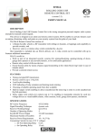
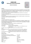
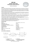
1
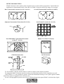
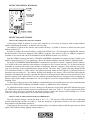
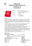
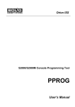
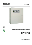
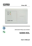
S2000-V
ADDRESSABLE VIBRATION INTRUSION DETECTOR
ISO 9001
INSTRUCTION MANUAL
DESCRIPTION
Addressable Vibration Intrusion Detector S2000-V (referred to as detector below) is designed to detect
break-in attempts to:
• Concrete walls and ceilings in thickness of at least 0.12 m
• Brick walls in thickness of at least 0.15 m
• Wood constructions in thickness of 20 to 40 mm
• Plywood in thickness of at least 4 mm
• Wood clip board in thickness of at least 15 mm
• Safes, cabinets, doors, automatic teller machines (ATM), and other enforced physical areas.
The S2000-V detector is to be mounted on a protected surface. It senses vibrations caused by an attack,
any gaps or crack in the material, and when the protected surface is shaken the detector generates an alarm
signal.
The detector operates as a part of Orion security system and is connected to a S2000-KDL two-wire
communication line controller powering it and receiving the alarm signal if happened.
S2000-V detector is designed to work around-the-clock.
FEATURES
•
•
•
•
•
Sensitivity adjustability for different applications
LED indicating of current operating mode and protected construction vibration
Net address programming and bidirectional S2000-V to S2000-KDL data communication
Sabotage protection due to a built-in tamper switch enabling to detect unauthorized cover removing
Protection against removal of detector from its mounting surface
SPECIFICATIONS
Power Supply
Consuming Current
Power-Up Operation Readiness
Operating Temperature Range
Relative Humidity
Overall Dimensions
Weight
from S2000-KDL via 2-wire communication line
2 mA maximum
5 s maximum
−30 C to +50 C
up to 93% (for +40 C) non-condensing
68×43×20 mm
about 25 g
DELIVERY SET
S2000-V Detector
Instruction Manual
Screw nail 1-4х30.20.019
Screw М4x25.48.016
Screw nut М4-6Н.5.016
Spacer 4.65Г.019
Spacer 4.04.019
Anchor 72204 MSA 4
Package
1 pcs
1 pcs
1 pcs
1 pcs
2 pcs
1 pcs
2 pcs
1 pcs
1 pcs
1
DETECTOR MOUNTING
S2000-V detector can be used to protect separate areas or entire surfaces in premises. Typical detector
application is demonstrated below, where A1 is a S2000-V detector and L is the range (or coverage).
Basic Construction Protection (S1>75%, S2<25%)
Overall Construction Protection (S=100%)
Adjacent Construction Protection (L2=3/4 L1)
Sash Frame Protection (L=L1+L2)
Non-Monolithic Construction Protection
22
(S<0,1м2, L1<L2)
Hollow Core Door Protection
ATM Unit Protection
Safe Protection
To fix a S2000-V detector onto the brick or concrete surface use the anchor provided.
To mount the S2000-V detector onto the wood or wood clip board surface use the supplied screw nail.
If the S2000-V is to be installed to protect ATM unit mechanism housing or user panel against vandals
attach it by means of supplied screw and screw nut.
In case of being applied to protect steel safe or ATM unit deposit box paste S2000-V with the help of glue.
2
DETECTOR WIRING DIAGRAM
DETECTOR ADJUSTMENT
HOW TO SET THE DETECTOR NET ADDRESS
Connecting a S2000-V detector to a two-wire controller it is necessary to assign it with a unique address
number identifying the S2000-V within the two-wire line.
Net address is stored in the detector non-volatile memory. A S2000-V detector is delivered with preset
address value of 127.
In order to change the network address, connect the S2000-V to a PC (through the S2000-KDL and any
RS-485 interface converter) supplied with UPROG program. The current version of UPROG program is
available in free mode and can be downloaded from the BOLID website www.bolid.ru.
Run the UPROG program and select CHANGE ADDRESS command with current and new S2000-V net
number (ranged from 1 to 127) as parameters. Write the assigned address onto the S2000-V Marking Field.
By means of ADDRESS PROGRAMMING command it is possible to define a required detector address.
It is useful in the event when the same address is assigned to two or more detectors. To do this activate the
command in question with required net number as parameter from the computer. Then make the long-longlong-short pressing on the required detector tamper switch. The term “long” signifies keeping during at least
0.6 s and no more than 5 s, while “short” one signifies pressing within no more than 0.6 s, the pause between
pressings not exceeding 10 s. The address having been changed, the detector LED will flash triply and the
computer will display the message reporting the detector with programmed address having connected. If two
detectors had the same address before the new address programming then the computer will not display the
detector with former address disconnection. Do not forget to write the assigned address onto the S2000-V
Marking Field.
To learn more about giving of net numbers to addressable devices included into two-wire communication
line refer to S2000-KDL controller, S2000(M) console, or ARM Orion User’s Manual.
To adjust the detector remove its cover, then power the detector on and wait until LED indicator has gone
off. When delivered the detector operates in technological mode (see Table 1). To enter setting mode make
long-short-short-short-long pressing on the detector tamper switch, the detector LED flashing once. In the
event of a wrong pressing, wait for 10 seconds and repeat pressing.
HOW TO ADJUST THE NOISE SENSITIVITY THRESHOLD
Press the detector tamper switch and hold it for 1 ÷ 5 s. The detector LED will flash twice indicating
second mode having entered (see Table 1). Turn the Sensitivity Adjustment Control to its left end position
that complies with maximum sensitivity.
If the detector has perceived a vibration it flashes triply, accumulates impacts and then generates an alarm
signal, LED indicator being lighting steady within 3 s.
3
In order to adjust the detector sensitivity, turn the Sensitivity Adjustment Control clockwise slowly to find
the position the LED indicator doesn’t light up near the noise of ordinary level.
HOW TO CHOOSE THE DETECTOR OPERATING MODE
All detector available operating modes are shown in Table 1. When received the detector is in
technological mode. The suitable operating mode (which can be 2, 3 or 4) can be chosen by experiment
depending on required impacts to be detected.
Operation mode testing is carried out in accordance with the technique demonstrated in Table 2.
Press on the detector tamper switch as many times as required mode number, each pressing increasing it
by one. The number of LED flashes indicates the number of chosen mode. After fourth mode the first one
will be indicated.
Having completed testing save the chosen operating mode by pressing and holding the tamper switch for
more than 5 s, LED indicator being light up in the event of success. Then the detector enters the operating
mode in accordance with chosen technique.
Finally, replace the detector cover.
Table 1: S2000-V Detector Available Modes of Working
Mode
1 Technological Mode (when delivered)
2 First Threshold Value (can be chosen)
3 Second Threshold Value (can be chosen)
4 Combined 2 and 3 (can be chosen)
Operating Mode (when chosen)
4
Description
The S2000-V detector is signaling an alarm and is not
response on any impact. LED indicates a detector
removal from its mounting surface flashing with 2 Hz
frequency.
The S2000-V detector senses long periodically
impacts, the LED flashing by three in series. After
impact having accumulated, the detector generates an
alarm signal being lighting steadily within 3 s. Then
the alarm is dropped. The LED flashes with 2 Hz
frequency indicating detector removal from its
mounting surface.
The S2000-V detector senses short periodically
impacts, the LED flashing singly. After impact having
accumulated, the detector generates an alarm signal
being lighting steadily within 3 s. Then the alarm is
dropped. The LED flashes with 2 Hz frequency
indicating detector removal from its mounting surface.
The S2000-V detector senses both short and long
periodically impacts, the LED flashing in accordance
with detected vibration behavior.
The detector cover has been being put on and the
tamper switch has been being closed for more than 5 s.
The LED behavior corresponds to chosen operating
technique.
Table 2: Testing of Operating Techniques
Material or Unit to Be Protected
Mode
Steel cabinet, safe, door, ATM unit deposit box
2
Wood, plywood, or wood clip board
2
Concrete or brick construction
3
ATM unit user panel
3
Simulative Impact
Application and Detector
Sensitivity Monitoring
Comment
Plane thickness
Put a steel plane onto
is 5-7 mm, drill
protected surface as far as
bit diameter is 3possible from the detector.
5 mm, and drill
Drill the hole into the plane
rotation
until LED has become
frequency is
flashing by three in series
1500-2500 rpm
The block size is
Attach a wood block at the approximately
boundary of a protected 75×75×300 mm,
zone. Saw the block until saw tooth pitch is
LED has become flashed in
5-10 mm, saw
short threefold manner
gullet depth is 4-8
mm
Apply a plane made of
fabricor
paper-based Plane thickness is
laminate to an edge of a 10-20 mm, plane
construction protected zone.
size
Lay a number of hammer approximately
blows on this plane until
150×150 mm,
LED has flashed singly
hammer weight is
Implemented as mentioned 0,4-0,6 kg; pauses
above. Lay hammer blows between blows
through a plane on different are from 0,1 up to
30 s
user panel areas simulating
attack
5
S2000-V DETECTOR OPERATING
A S2000-V detector being powered up, the detector LED will light, and the RESTART message will be
transmitted to a S2000-KDL controller signaling self adjustment being in process. Do not take any actions or
touch detector or protected construction until LED has gone off!
After self adjustment having been successfully completed the S2000-V LED goes off and the S2000KDL controller receives the NORM response.
In case of any destructive effect having detected the S2000-V detector transmits the ALARM message
to the S2000-KDL controller. The attack having been stopped, the detector has been recovering within 10 s.
If a detector removal from its protected mounting surface is detected S2000-V transmits a TROUBLE
message to the S2000-KDL controller, the detector LED flashing with 2 Hz frequency until the trouble
having been repaired. When recovered, the detector restarts. If no, reset the detector manually by having
disconnected from two-wire communication line or by having made short-long-short-short-short pressing on
the detector tamper switch (that is, having made a program reset). More specifically the detector indication
and operating techniques are described in S2000-KDL controller User’s Manual.
OVERALL AND MOUNTING DIMENSIONS
All dimensions are defined in mm.
6
WARRANTY
Manufacturer warrants its S2000-V Addressable Vibration Intrusion Detector to be in conformance
with specification under normal transportation, storage, mounting and maintenance.
Manufacturer warrants its product to be free from defects in materials and workmanship for 18 months
since putting the S2000-V detector into operation, but no more then 24 months since production under
normal use and service.
In the event of in-warranty failure having occurred within warranty period the failed S2000-V detector
should be replaced with known good device by manufacturer.
Ship off a failed S2000-V detector to the manufacturer for exchange with a damage certificate
describing the defect and its acceptance certificate to validate the warranty status. Send your complaints
to the manufacturer at the following address:
ZAO NVP BOLID
#4, Pionerskaya street, Korolyov, Moscow Region, Russia, 141070
Tel./fax +7 495 777-40-20, +7 495 516-93-72.
E-mail: [email protected], Web-site: http://www.bolid.ru
7
ACCEPTANCE CERTIFICATE
S2000-V Addressable Vibration Intrusion Detector
Product Designation
Serial Number
Produced, tested by quality control department in compliance with state standards and specifications, packed
by NVP BOLID Company and qualified as deliverable.
Q.C.
STAMP
8
_____________________
Name
____________________________
Date