1
www.vaidsys.ru
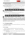
E1 LOS LED blinks when respective input E1 signal is AIS, i.e. the content of
E1 data is all 1’s. Such alarm
indicat es fault conditions on the part of the
downstream equipment.
E1 LOS site is controlled by Dip Switc h RA state. W hen RA Dip Switch ON,
the red LEDs indicate remote E1 LOS state. When RA Dip Switch OFF, the red LEDs
indicate local E1 LOS state.
The E1 PKT LOS lights are packet loss indicator, On for Ethernet packet loss, Blink
for E1 Packet Loss, Off for Normal.
4.2 Lnk/Act LED off
Lnk/Act LED off means the corresponding Ethernet link is not working. Check
the Ethernet cable connection, and the status of the device on the other end of the
cable.
4.3 Ready LED does not blink
After power on, the Ready LED should star t to blink. If not, try switch power
off and on again. If this error persists, call for support.
4.4 Can not built communication
Two ends of equipm ents are in one Et hernet broadcast dom ain, check the IP
dual relations is right and MAC address should be unique.
4.5 Downstream reporting slips
Check if the downstream equipm ent has correct clock m ode. At least one of
them must be clock master. Set the EthMux on master side to loop back timing.
If the downstream equipm ent on both side s is not synchronized, slips are not
avoidable.
At the transition time after power on or reapplying the E1signal, slips and errors
are acceptable. Such transition may take several minutes.
5.
Web Manager
Both Web Server and SNMP management are supported through anyone of two
Ethernet ports of MX-30/60
The management has four sections: Status, Line Test, Configuration and System.
User nam e and password are required to
enter the sections of Line Test
Configuration and system . Both the defa ult user nam e and password are “root”.
Customers can modify the user name and password in the System section.
Note that the modifications of system will be valid after submit and reboot,
- 12 -
MX-30
and MX-60
User Manual V1.2