1
www.vaidsys.ru
through the local Ethernet ports on th
e MX-30/60 s. This configuration
guarantees that the E1 channels get higher priority over com puter data for maximum
QoS.
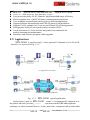
The m ost widely used application of MX-30/60 is to set up point to point
wireless E1 links using low cost wireless LAN bridges. MX-30/60 can work with
most LAN bridges on the m arket. It may be necessary to adjust different param eters
such as packet size and packet jitter absorption buf fer size f or best operation f or
different LAN bridges.
WARNING: When connecting to a wireless LAN bridge, the uplink
Ethernet cable often connects to the outdoor unit, posing danger to lightning
strikes that can seriously damage the equipment. To protect the equipment as
well as people, surge protection devices with good earth connection is strongly
recommended. Poor earth connection may also hinder the operation of the
Ethernet port, causing severe packet losses.
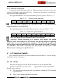
1.4 Timing modes
To emulate a clear E1 channel over a packet network, the MX-30/60 not only
conveys data stream content correctly from the source to the destination, but also
passes tim ing. Packet networks do not provi de such built-in tim ing transparency
mechanism as TDM networks do. MX-30/60 uses its proprietary algorithm to
reconstruct the E1 clock at the destina tion. The recovered clock is of very high
quality, with low jitter and wander. Typi cal frequency offset is within ±5ppm, and
jitter is below 0.1UI. It can be adopted in most applications. This tim ing m ode of
rebuilding the E1 clock at the destination is called Adaptive Timing.
For applications where separate cloc k distribution network exists, another
timing mode, Loop back Timing, may be used for maximum clock quality.
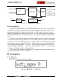
The two timing modes of MX-30/60 are depicted in Fig.1.4-1.
E1 IN
E1 IN
EthMux
E1 port
EthMux
clock
extract
E1 port
clock
reconstruct
E1 OUT
Adaptive Timing
buffer
E1 OUT
Loop back Timing
Fig.1.4-1 E1Timing modes
Correct timing mode setting is im portant for sm ooth operations. In m ost cases,
setting both units to adaptive tim ing mode is suf ficient. But som etimes, setting one
unit to loop tim ing mode may work better. For exam ple, setting the MX-30/60
unit connected with the clock m aster (suc h as local exchange) to loop back m ode,
and the other unit connected with the clock slave (such as PBX or remote module) to
MX-30
an d
MX-60
User Man ual V1 .2
-3-