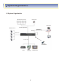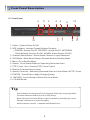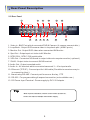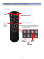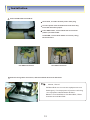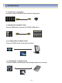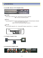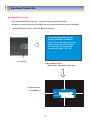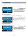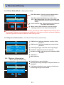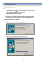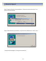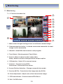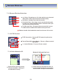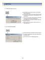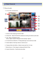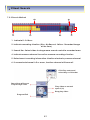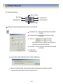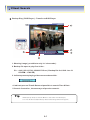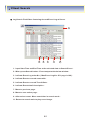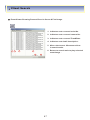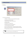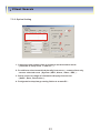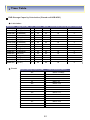
1
Triplex MP4 SDVR
Stand Alone Type
DVR SYSTEM
MANUAL
Fir mware 2.0 Version
Revision Date : 2005.01.31
Firmware ver 2.0
Modification Date : 2005.01.31
Please refer the below message to confirm the modify contents.
1. PTZ CONTROL
* ADD PRESET FUNCTION : FOR PELCO-D PROTOCOL
* ADD SWING FUNCTION : FOR DONGYANG CAMERA ( D-MAX )
2. CD-RW ( CD Read & Write Burner )
* ADD CD-RW FUNCTION FOR DATA BACKUP
3. IE BROWSER
* ADD IE BROWSER ( ALLOW FOUR USERS MONITORING AT
THE SAME TIME )
1
INDEX
CHAPTER 1. ( Specification & System Organization )
1.1 Specification ------------------------------------------------------------------------------ 5
1.2 Product Contents List ------------------------------------------------------------------ 6
1.3 System Organization ---------------------------- -------------------------------------- 7
CHAPTER 2. ( Description )
2.1 Front Panel -- ----------------------------------------------------------------------------- 8
2.2 Rear Panel -------------------------------------------------------------------------------- 9
2.3 Remote Controller ---------------------------------------------------------------------- 10
CHAPTER 3. ( Installation )
3.1 Hard Disk Installation -- --------------------------------------------------------------3.2 Camera Connection ------------------------------------------------------------------3.3 Monitor Connection ------------------------------------------------------------------3.4 Computer Connection -- -------------------------------------------------------------3.5 Network Connection -----------------------------------------------------------------3.6 Alarm/Relay/PTZ Connection ------------------------------------------------------3.7 Power Connection -- ------------------------------------------------------------------3.8 Finishing Installation ----------------------------------------------------------------% Hard Disk format --- -------------------------------------------------------------------
11
13
13
13
13
14
14
14
15
CHAPTER 4. ( Monitoring )
4.1 System Power ON -- ----- --------------------------------------------------------------4.2 Select Screen Mode ------------------------------------------------------------------4.3 Convert Screen Mode ----------------------------------------------------------------4.4 Control PTZ/Focus -- -----------------------------------------------------------------4.5 System Power OFF ---------------------------------------------------------------------
16
17
17
17
18
CHAPTER 5. ( Search )
Go to Search -------- ----- --------------------------------------------------------------- 19
5.1 Search by Date/Time ------------------------------------------------------------------ 19
5.2 Search by Event ------------------------- ----------------------------------------------- 20
2
INDEX
CHAPTER 6. ( Menu )
Go to Menu -- ---------------------------------------------------------------------------- 22
Menu Initial ----------------------------------------------------------------------------- 22
6.1 Display ----------------------------------------------------------------------------------- 23
6.2 Record -- -------------------------------------------------------------------------------- 23
6.2.1 Size/Rec. Rate/Quality -------------------------------------------------------- 23
6.2.2 Timer Recording Setup ------------------------------------------------------ 24
6.2.3 Motion Detection Setup -- ---------------------------------------------------- 25
6.2.4 Alarm Recording Setup ------------------------------------------------------- 25
Time Recording Weekly Setup --- ------------------------------------------ 26
Partial Motion Region Setup --- -------------------------------------------- 27
6.3 Camera -- -------------------------------------------------------------------------------- 28
6.3.1 Status/Title Setup -------------------------------------------------------------- 28
6.3.2 Covert/PTZ Setup ------------------------------------------------------------- 28
6.3.3 Color Setup -- -------------------------------------------------------------------- 29
6.4 Audio -- ---------------------------------------------------------------------------------- 29
6.4.1 Audio Recording Setup ------------------------------------------------------ 29
6.4.2 Live Audio Setup -------------------------------------------------------------- 30
6.5 Alarm -- ---------------------------------------------------------------------------------- 15
6.5.1 Alarm Input Setup ------------------------------------------------------------- 15
6.5.2 Relay Output Setup ---------------------------------------------------------- 16
6.6 System -- -------------------------------------------------------------------------------- 15
6.6.1 Date/Time -- ----- ----------------------------------------------------------------6.6.2 Network --------------------------------------------------------------------------6.6.3 Buzzer Setup -------------------------------------------------------------------6.6.4 Password -- ----------------------------------------------------------------------
18
18
19
19
6.6.4.1 Administrator Password -- ----- -----------------------------------6.6.4.2 Manager Password --------------------------------------------------6.6.4.3 Operator Password -------------------------------------------------6.6.4.4 Network Password -- ------------------------------------------------6.6.5 Disk Write Mode -- --------------------------------------------------------------
18
18
19
19
19
6.6.6 System Information -- ----- --------------------------------------------- 18
6.6.7 Factory Default ---------------------------------------------------------- 18
6.6.7 CD-RW Backup -- --------------------------------------------------------------- 19
3
INDEX
CHAPTER 7. ( Remote Agent )
System Requirement -- --------------------------------------------------------------- 38
DVR Remote Agent 1.0 Installation ------------------------------------------------ 39
7.1.1 Monitoring -- ------------------------------------------------------------------------7.1.1 Function Introduction -------------------------------------------------------7.1.2 Screen Division Selection -------------------------------------------------7.1.3 PTZ Control -- ------------------------------------------------------------------7.1.4 Selection Network ID ----------------------------------------------------------
15
15
16
16
16
7.1.5 AVI File Conversion -- --------------------------------------------------------- 16
7.1.6 Color Adjustment -------------------------------------------------------------- 16
7.2 Search -- --------------------------------------------------------------------------------7.2.1 Function Introduction -------------------------------------------------------7.2.2 Search Method ----------------------------------------------------------------7.2.3 Search Option -- -------------------------------------------------------------7.3 Setting -- -------------------------------------------------------------------------------7.3.1 Connection ID Setup --------------------------------- ----------------------7.3.2 Option Setting -----------------------------------------------------------------
15
15
16
16
15
15
16
CHAPTER 8
Time Table ------------------------------------------------------------------------------------ 53
PTZ Protocol -------------------------------------------------------------------------------- 54
PTZ Control ------------------------------------------- ------------------------------------- 55
PTZ Reset ----------------------------------------------------------------------------- 56
Swing --------------------------------------------------------------------------------- 56
Cross Cable Making Tip --------------------------- ------------------------------------- 55
4
Specification & Organization
CPU
Hardware
32 bit DSP
Unlimited HDD x 1 ~ 4
HDD
OS
RTOS
Video Input
4CH NTSC/PAL
Display Speed
120 ( PAL: 100 ) fps
Display Modes
Full , Quad , Sequence
Recording Speed
352 x 240
120 / 100
704 x 240
60 / 50
704 x 480
30 / 25
Monitor Output
BNC / S-Video / 4 loop-out / 1 Spot-out
NTSC : 352x240 , 704x240 , 704x480
Recording Resolution
PAL : 352x288 , 704x288 , 704x576
Compression Method
MPEG4 ( Optimized )
3~5 Kbyte@ 352x240 ( PAL : 352x288 )
Byte Size per Image
5~10 Kbyte@ 704x240 ( PAL : 704x288 )
6~16 Kbyte@ 704x480 ( PAL : 704x576 )
Continuous , Motion , Alar m
Recording Modes
Recording Schedule
Schedule setting per camera
Motion Detection
132 grids setting per camera
Audio input / Output
4 inputs / 1 output
Sensor / Alar m
4 inputs / 1 output
VGA Output ( Optional )
1 CII
PTZ Control & Por t
RS-485
Network
TCP/IP , IE , AP
Inter net viewers
Allow 4 viewers on the line at the same time
Password
4 password level
LAN , CD-RW , Inter net
Back-up
Search Modes
By Time & Event
Search Speeds
Up to 64 on both forward & backward
80G HDD Storage Capacity ( hour )
Resolution
CH & Frames
Highest
High
Standard
Low
4CH ( CIF/30FPS )
41
58
93
154
4CH ( 2CIF/15FPS )
37
46
74
123
4CH ( D1/7FPS )
19
23
38
61
4CH ( D1/1FPS )
93
132
154
185
This Value is for continuous recording in bright place and large movement .
So it can be extend 2 ~ 3 times for ordinary environment .
5
Packing Contents
1.2 Product Contents List
Please confirm the contents when you open packing .
1
Basic Contents
DVR Machine
User Manual
2
12 Adaptor
Remote Controller
Optional Devices
IDE HDD
VGA Out & GOIP Port
6
Power Cable
Remote Viewer CD
System Organization
1.3 System Organization
Alarm Sensor #1- 4
Relay Out
Client PC
Alarm Input/Out
Camera # 1- 4
Network
TCP/IP
Video In
Video Out
Remote
Controller
VCR
VGA
Monitor
7
AV Monitor
Front Panel Description
2.1 Front Panel
2
1
3
4
12
6
5
10
9
7
8
11
1. Power : System Power On/Off
2. LED Indicator : Indicate Present System Situation
( POWER : System On/Off , RECORD : record On/Off , NETWORK :
Client Network Connect On/Off , ALARM : Alarm Sensor On/Off )
3. Channel Select Button : When Select Channel or Input Password
4. SCR Mode : When Select Screen Division Mode or Rotation Mode
5. Menu : Go to System Menu
6. Search : Go to Search Mode for Searching Recorded Video
7. PTZ / Focus : Go to Camera PTZ / Focus Control
8. Remote Controller Sensor Input
9. Search Controller : Searching Recorded Video or Control Menu & PTZ / Focus
10. ENTER : Press Enter to Apply Changing Setup
11. RETURN : Cancel Setup or Return Previous Mode
12. CD-RW Burner
Tip
Power Button is soft style to Prevent System Failure by wrong operation .
Channel Selection Button is prior to SCR mode .
When Remote Controller Sensor Input is blocked by something it cause
Remote controller do not work properly .
When press any button . It operate with Beep Sound .
8
Rear Panel Description
2.2 Rear Panel
¨ç1
3
6
¨é
¨è
2
¨ê
4
9
¨ì
¨ï
¨ë ¨í ¨î
5
7
8
11
¨ñ
12
¨ò
¨ð
10
¨ó
13
1. Video in : BNC Port which connected DVR & Camera ( 4 camera connect able )
2. Loop Back : Output DVR camera video to loop back port ( 4 BNC ports )
3. Monitor Out : Output DVR video when connected AV Monitor .
4. Spot Out : Output spot out video to AV Monitor
5. NTSC/PAL : NTSC / PAL switch able .
6. VGA Out : Connected VGA card to output video at computer monitor ( optional )
7. SVHS : Output video to connect SVHS terminal
8. Audio Out : Output recorded audio
9. Audio In : AV terminal which connected camera # 1 ~ 4 for input audio .
10. Ethernet (TCP/IP) : Connect port for LAN cable (Possible to remote survey to
to connect to client )
11. Alarm/relay/RS-485 : Connect port for sensor & relay , PTZ
12. RS-232 : For program debug & expand connection (not available now )
13. DC Power Input Terminal : Power supply by DC 12V Adaptor .
Tip
• When System Installation, Please Connect when System Off.
• Please Use Specific Adaptor when Power Supply.
9
IR Remote Controller Description
2.3 IR Remote Controller
POWER
System
ON/OFF
RETURN
Cancel
Setup or
Return to
Previous
MENU: Open menu
Channel Select Button
(4ch Available, #1~4 Button)
ENTER: Apply Setup Change
Search Controller : Control Playback Option
( EX. Speed of Playback, Move on Menu,
1 Control PTZ/Focus)
Change
Screen Mode
PTZ/IRIS
Mode
Open
Search Mode
10
Installation
3.1 Hard Disk Installation
1
Jumper Setup Master or Slave
Jumper Setup as Master or Slave refer to explanation
of surface Hard Disk .
Jumper is located at Hard Disk data cable or rear side
of Hard Disk .
If one Hard Disk installation , setup as Master
If two Hard Disk installation , second one setup as slave
!! When Hard Disk add or exchange, must system off
properly ( power button system off ) if not , it a cause
Of fatal error of disk .
Example of Samsung HDD Jumper Setup
Refer to general pin setting in jumper pin setting on HDD
Surface .
When one HDD installed , setup pin as Master and connect
Pin at the left end of jumper .
When two HDD installed or add HDD, one is for Master and
The other is for Slave. Slave setup has No pin .
When mor than two HDD installation, setup as Master &
Slave to connect one IDE cable the same method of above .
!! Please use HDD which can supply higher than UDMA66 !!
3
IDE Cable Connection to Main Board
Confirm the IDE cable inside of product
Among the three connector, indicated blue color
Connector must be connected with main board ,
Other connectors connected with HDD .
11
Installation
3
Connect IDE cable to Hard Disk
Insert disk, red cable head to power cable plug
Connect power cable to Hard Disk in the same way
Pin at the left end of jumper .
If one HDD install, connect with end of connector
( Black ) recommended .
If add HDD, connect with middle connector ( Gray )
Recommended .
Two HDD Installation
One HDD Installation
4
After finishing cable connection, attach Hard Disk with screw & bracket
Tip
Master , Slave ?
IDE Hard Disk can connect two equipment at one
Cable (port). For the purpose of prevent confusing
, two equipment named Master & Slave .
Master is one Hard Disk or first Hard Disk , Slave
Is below second Hard Disk .
12
Installation
3.1 Hard Disk Installation
Connect camera at BNC port in back side panel .
3.3 MONITOR CONNECTION
Connect Monitor terminal or S-VHS to Monitor .
3.4 COMPUTER CONNECTION
Connect VGA out to computer monitor .
3.5 NETWORK CONNECTION
Connect Ethernet terminal and network cable to Internet .
13
Installation
3.6 ALARM / RELAY / PTZ CONNECTION
1
1
2
3
ALARM
Alarm Input - 1N1,1N2 , 1N3 : connect sensor input by channel
GND : Connect to Ground system .
2
RELAY
Alarm Output NO , NC : After checking Alarm output type ( Normal Open or Normal
Close ) and connect to NO , NC .
COM : Connect remain grounding conductor .
3
RS-485
Connect PTZ camera D+ , D- : Connect PTZ camera control line ( + , - terminal )
RS485
PTZ 14 Pin Cable
D+
D-
9
¨ï
R+
10
¨ð R11 T+
¨ñ
¨ò
12 T-
3.7 POWER CONNECTION
3.8 FINISHING CONNECTION
14
System Power On
Hard Disk Format
- If do not new Hard Disk format , system can t recognize the HDD .
So there is same situation of No HDD, please format HDD when insert new HDD
( Only Display possible , not work Menu & Search )
Checking Hard Disk Drives ...
Disk0 [SANSUNG SP0002N]
Total 1 Hard Disk Drive Found.
New System Disk Detected.
All Disks will be formatted.
Format All Disks ? NO (0)
1. Power On
2. New HDD Format
( Select Play , Backward Play key )
3. System Start
SETUP
( Initial Mode )
User
Password
15
Administrator
System Power On
4.1 SYSTEM POWER ON
Press Power button to start system
After checking Hard Disk, need input password
to operation .
Initial screen view mode is quad division mode
and recording mode .
CAMERA
Picture Power On
After finishing installation
2004/01/01
00:00:00
Each channel indicate camera Name & Recording
Status .
Present Time & Date indicate at monitor central
Lower side .
Tip
• Check System Condition at LED
POWER : Showing System On/Off
RECORD : Showing Record On/Off
NETWORK : Showing Client Connection Status
ALARM : Lighting whenSensor Alarm Activate
4.2 SELECT SCREEN MODE
Select one channel among 4 channels
Move to one enlargement watch mode when
Quad Screen division mode .
Move to one enlargement watch mode when
Rotation mode .
16
System Power On
4.3 Convert Screen Mode ( SCR MODE )
User can select 3 kinds watch mode :
SCR MODE
% Quad (4CH) division watch mode
% Selected 1CH watch mode
% 4CH rotation watch mode
Quad (4CH) watch mode is initial mode when system start
Selected 1CH
Watch Mode
Quad (4CH) Division
Watch Mode
4CH Rotation Mode
4.4 PTZ / FOCUS CONTROL
Control camera PTZ (Pan/Tilt/Zoom) & Focus (Only
Useable for proper camera .
PTZ/FOUCS
Press PTZ/FOCUS button to open PTZ Menu at rightNder side and control by search controller .
Press PTZ/FOCUS button second time to open focus
/IRIS Menu and control by search controller .
PTZ CTL
UP
LEFT RIGHT
DOWN
Control Camera PTZ &
Focus by Search
Controller on PTZ Menu
FOCUS/IRISCTL
UP
LEFT RIGHT
DOWN
Search Controller
17
System Shut Down
4.5 SYSTEM POWER OFF
SHUTDOWN
Administrator
User
Password
Press Power button to system off
Input Password and press Enter to shutdown
system .
Tip
System Log-on password : Administrator , Manager , Operator , Network
Administrator : All function access ( system on , shutdown , stop , search )
Manager : System on and Search
Operator : System On
Network : Connect by remote program
18
SEARCH
Go to Search Mode
SEARCH
Search
1. Search by Date/Time
>
1. Search by Date/Time
>
Press search button and Log-in
Administrator or manager
Use direction key to move menu
ENTER
RETURN
Search Recorded Data
To open each menu press enter
Return to Previous
( Move to previous Menu or Exit Search
Mode and return to watch mode )
5.1 SEARCH BY DATE/TIME
- Possible to Search Recorded Date & Time
Move cursor to selected date in calendar
Mar
2004
Sun Mon Tue Wed Thu
1
2
3
4
10
11
7
8
9
14
15
16
17
21
22
23
24
28
29
30
31
18
25
( Recorded Date&Time indicated by gray color )
Fri Sat
5
6
12
13
19
20
26
27
Press Enter to open selected date
Recorded Time appear to under side
Press Enter at selected time
4
1
2
3
8
9
10
11
15
16
17
18
5
6
7
12
13
14
19
20
21
( One scale is 15 minutes )
Menu disappear and output recorded video
Showing recorded Date&Time at left-upper side
as watch mode .
Showing playing condition at right-under side .
Channel selection button in watch mode & SCR
Mode button are apply the same as search mode .
( but Menu , Search , and PTZ/FOCUS buttons
are Exception )
19
2004.01.01
00:00:00
SEARCH
Control Playing Video
1
: Basic playing mode ( normal speed (1x) forward playing )
2
: Normal speed backward playing
3
: Pause video
4
: Fast forward ( 2 ~ 64 speed )
5
: Fast backward ( 2 ~ 64 speed )
6
: Same function as
4
~
5
Press normal forward backward button in pause . Move to next / previous frames
5.2 SEARCH BY EVENT - Searching video with event occurrence to setup period
- Setup period to select start date & finish
Date for searching event .
EVENT VIEW
Start Time
2005. 07. 07. 00.00
End Time
2005. 07. 07. 00.00
Alarm
Motion
Date
Time
Timer
- Alarm : Searching alarm event during the
Selected period .
System
Event
Start Search
- Motion : Searchng motion detected event
During the selected period .
- Timer : Searching schedule change or
Recording setup change event .
- System : Searching power On/Off event
(Etc.) Concerned system event .
- Event list showing at below output window
Tip
Alarm , Motion , System can be select plural by check (V)-(Enter)
To change setup , press enter and press direction key
After changing setup . Press enter to exit .
20
SEARCH
Date : Indicate event occurrence order
& date .
EVENT VIEW
Start Time
2005. 07. 07. 00.00
End Time
2005. 07. 07. 00.00
Alarm
1. 2005.01.31
2. 2005.01.31
3. 2005.01.31
4. 2005.01.31
5. 2005.01.31
6. 2005.01.31
7. 2005.01.31
8. 2005.01.31
Event : Indicate event contents & cam
Start Search
System
Motion
Date
Time : Indicate event occurrence time
Time
11:00:41
11:00:41
11:00:41
11:00:41
11:00:41
11:00:41
11:00:41
11:00:41
No .
Event
Rec. Start Schedule
Rec. Start Schedule
Rec. Start Schedule
Rec. Start Schedule
Camera CH1 OFF
Camera CH2 OFF
Camera CH3 OFF
Camera Ch4 OFF
CH1
CH2
CH3
Ch4
Event searching method
User can search event by direction key
Search event to please enter at selected event from event occurrence time .
Control video is the way as time moce
control .
Tip
The search by event is not base on video , but event occurrence
Time .
21
MENU
Go to Menu
Press menu button on front panel in watch
Mode .
SETUP
User
Ask password
Administrator
Input password using by channel select
Button [1] [2] [3] [4] .
Password
After input password press Enter to see Menu
Tip
Initial Administrator , User , Network password is 1234 .
Showing password as *
Changing password (Menu->6.system->4.password)
Only watch mode can go to Menu .
( Search & PTZ/FOCUS mode can not move to Menu )
Menu Initial
Every system setup can change or
Maintain at Menu ( 6 setup ) .
MENU
1. Display
>
2. Record
>
3. Camera
>
4. Audio
>
5. Alarm
>
6. System
>
Move to Menu using by up
& down button .
•
•
22
ENTER
RETURN
To open detail Menu
Or to apply input .
Return to previous Menu or
Return to watch mode .
MENU
6.1 DISPLAY
- video setup for display mode
1. Date / Time : Date & Time mark On/Off
2. Title : Camera name On/Off
1. Display
1. Date / Time
On
2. Title
On
3. Status
On
4. Border
On
5. Border Color
GRAY
6. Sequence Dwell
3 Sec
7. Spot-out Dwell
3 Sec
1. Deinterlace Mode
Off
3. Status : Record condition mark On/Off
( Recording : Red . Pre-recording : green )
4. Border : Border mark On/Off
When 4CH division watch mode
5. Border color : Select border color
( White . Blue . Red . Yellow . Green . Gray )
6. Sequence dwell : setup rotation cycle time
(1~60 sec) when 4CH rotation mode at Display
7. Spot-out dwell : setup spot-out time cycle
(1~60 sec) to transmit video
8. Deinterlace mode : Remove screen spread on
High resolution . Low frame
Only applying when D1 (704x480)
6.2 RECORD
- Setup image record
6.2.1 Size/Rec. Rate/Qality Setup Recording Resolution , Compression Rate , quality
2. Record
1. Display
1. Size / Rec Rate / Quality
2. Timer Recording Setup
3. Alarm Recording Setup
Quality
Camera
Size
Rec.Rate
1
352x240
30
High
2
352x240
30
High
3
352x240
30
High
4
352x240
30
High
- Camera : Indicate Camera No. To Setup
- Size : Setup Resolution
- Rec.Rate : Setup Compression Rate
- Quality : Setup Quality of Recording Video
23
MENU
Size : 352x240 , 702x240 , 702x480
2.1 Size/Rec , Rate/Quality
Rec.Rate : Possible to select 1 ~ 30
Camera
Size
Rec.Rate
Quality
1
352x240
30
High
2
352x240
30
High
3
352x240
30
High
4
352x240
30
High
Quality : 3 Levels ( High , Low , Standard )
Indicate frame No. On Size & Rec , Rate
Frames Available
If frame over, showing the message and
Over limit Recording Capacity
Impossible to change Size & Rec and Rate
Tip
When setup please refer to below NTSC & PAL type
NTSC : 352x240 (120fps) . 704x240 (60fps) , 704x480 (30fps)
PAL : 352x240 (120fps) . 704x240 (60fps) , 704x480 (30fps)
Possible to setup Size & Rec.Rate. Quality per each channel
When applying change setup. Press Enter .
When cancel change setup. Press Return .
6.2.2 Timer Recording Setup - Record On/Off or Time, Motion Setup
Camera : Indicate camera No. To setup
2.2 Timer Recording Setup
Record : Record On/Off
Camera
Record
Start
Stop
1
On
0
24
2
On
0
24
3
On
0
24
4
On
0
24
Motion Detection Setup
Start : Setup Recording start time (0~24 hr)
Stop : Setup Recording finish time (1~24 hr)
* Recording time is between start time and
Finish time .
Motion : Motion detection recording On/Off
( Record setup must be On , when motion
detection recording ) .
24
MENU
6.23 Motion Detection Setup - Motion Detection Area & Sensitivity
Camera : Indicate camera No. To Setup
Sensitivity : Control Sensitivity (1~100)
Large No. Is more sensitive.
Region : Setup motion detect range
MOTION DETECTION SETUP
Camera
Motion
Sensitivity
Region
1
Off
5
Entirely
2
Off
5
Entirely
3
Off
5
Entirely
4
Off
5
Entirely
Pre Motion Duration
1 Sec
Post Motion Duration
30 Sec
Entirely Setup entire screen
Partially Setup partial screen
When choose region as partially. Move to
Partial range setup. Press Enter after
Range setup to finish region setup .
Pre-Motion Duration : Setup Pre-Motion
(1~5 sec)
Post-Motion Duration : Setup Motion detect
Recording time after motion detected (5sec
~ 3mm)
6.2.4 Alarm Recording Setup for Alarm Activated
Camera : Indicate camera No. To Setup
Record : Setup record On/Off when alarm
Alarm Recording Setup
Activated .
Camera
Record
Start
Stop
1
Off
0
24
2
Off
0
24
3
Off
0
24
4
Off
0
24
Pre Alarm Duration
5 Sec
Post Alarm Duration
30 Sec
Start : Setup alarm recording start time (0~24 hr)
Stop : Setup alarm recording finish time (0~24 hr)
Pre-Alarm Duration : When alarm recording.
Setup start recording time before alarm activate
(1~5sec)
Post-Alarm Duration : Setup Alarm Recording
Time after alarm activate (5sec~3min)
Tip
Motion setup work by time schedule and alarm schedule work
Independently .
25
TIME RECORDING
Time Recording Weekly Setup
1
2
TIMER RECORDING SETUP
MOTION DETECTION SETUP
Camera
Record
Mode
Start
Start
1
Off
Weekly
N/A
N/A
2
Off
Daily
0
24
3
Off
Daily
0
24
4
Off
Daily
0
24
0
12
2
14
1
13
4
16
3
15
7
19
6
18
5
17
8
20
9
21
11
23
10
22
Sun
Mon
Tue
Wed
Thu
Fri
Motion Detection Setup
Sat
Scheduled Region Indicted Yellow
Weekly Mode Setup
4
3
TIMER RECORDING SETUP
TIMER RECORDING SETUP
0
12
2
14
1
13
4
16
3
15
7
19
6
18
5
17
8
20
9
21
0
12
11
23
10
22
Sun
Sun
Mon
Mon
Tue
Tue
Wed
Wed
Thu
Thu
Fri
Fri
Sat
Sat
4
16
3
15
7
19
6
18
5
17
8
20
9
21
10
22
11
23
After selecting region and press Enter
again to finish Schedule setup ( Red ) .
After Deselect Schedule , Activated
region by press Enter and select Date
&Time to move cursor .
5
2
14
1
13
6
TIMER RECORDING SETUP
0
12
1
13
2
14
3
15
4
16
5
17
TIMER RECORDING SETUP
6
18
7
19
8
20
9
21
10
22
11
23
0
12
1
13
2
14
3
15
4
16
5
17
6
18
Sun
Sun
Mon
Mon
Tue
Tue
Deselect All
Wed
Wed
Save & Exit
Thu
Thu
7
19
8
20
9
21
10
22
11
23
Select All
Cancel
Fri
Fri
Sat
Sat
Select All : Entire Region Select
Deselect All : Cancel Region
Save & Exit : Save Changing Setup&Exit
Cancel : Cancel Changing Setup&Exit
Setup Date&Time schedule in the same
way after finishing schedule setup .
Press Return for Save & Exit .
26
TIME RECORDING
Partial Motion Region Setup
None-Activage Move Cursor
Activate Partial Setup Cursor
Partial Setup Finish Cursor
None Activate region
1
2
Move Cursor by Direction key
and press Enter at selected region
Region Initial View
4
3
5
Press Enter again to see region
as a blue color setup noneactivated region
Press Enter again to see region
as a blue color setup noneactivated region
6
Press Return to select multi
none activated region
Same method as 4 , 5 possible
to expand none activated region
8
7
Select All : Select Entire region
Deselect All : Cancel region setup
Select All
Deselect All
Save & Exit
Cancel
Save&Exit : Save the change setup
& exit
Cancel : Cancel change setup&exit
For reducing the partial region
cancel none activated region in
same way as 4 , 5
When finish partial region setup
, press Enter to Save & Exit
27
TIME RECORDING
6.3 CAMERA - Setup Camera
6.3.1 Status / Title Setup
Statues / Title Setup
Camera
1. Status/Title Setup
>
2. Covert / PTZ Setup
>
3. Color Setup
>
Camera : Indicate camera No.
to Setup .
Status : Indicate camera status
( Connected/Disconnected )
Tip
Camera
Statues
Title
1
Connected
CAMERA.......
2
Connected
CAMERA.......
3
Connected
CAMERA.......
4
Connected
CAMERA.......
Title : Setup camera name to
show left upper side
Title input mothod
Using direction key. Up & Down keys for alphabet A~Z .
Number 0~9 Left-Right keys for move to another letter .
6.3.2 Covert/PTZ Setup
Covert / PTZ SETUP
Camera
Covert
Address
PTZ Protocol
1
Off
0
PELCO-D
2
Off
1
PELCO-D
3
Off
2
PELCO-D
4
Off
3
PELCO-D
Baud Rate
Camera : Indicate camera No. To setup
Covert : Setup covert On/Off
* What covert ?
When covert on watch mode. Display
Video is hidden. But recording is on .
PTZ address : Select PTZ camera address
PTZ protocol : Select kind of PTZ camera
Baud Rate : Setup PTZ communication
Speed ( 2400.4800.9600 BPS )
9600 BPS
0
PTZ supplied protocol :
Samsung (MRX-1000). Honeywell (GC/GMC
755 Zoom) Kalatel (KTB312). Panasonic (WV-CS850,WV-CSR604) , Pelco-D , Pelco-P .
28
Menu
6.3.3 Color Setup - Control Video Color
Camera : Indicate camera No. To setup
Color Setup
Camera
Bright
Contrast
Color
Tint
1
50
50
50
50
2
50
50
50
50
3
50
50
50
50
4
50
50
50
50
Bright : Control monitor bright
Contrast : Control monitor contrast
Color : Control monitor color
Tint : Control monitor tint
* All setup possible to control 0 ~ 100
6.4 AUDIO
6.4.1 Audio Recording Setup
Audio Recording Setup
Audio
1. Audio Recording Setup
2. Live Audio Setup
>
>
Camera
Audio Rec.
1
OFF
1
2
OFF
2
3
OFF
3
4
OFF
4
Audio Ch.
Camera : Indicate camera No. For setup
Audio Rec : Setup recording On/Off
from external audio in terminal
Audio Ch : Setup audio in terminal channel & audio output camera
Tip
User can listen saved audio with saved video
Audio check in search is possible only normal speed (1x)
Forward playing at 1 Ch mode (audio recorded channel).
29
Relay & Audio
6.4.2 Relay output setup alarm relay setup
Relay Output Setup
Alarm : Indicate alarm input terminal No.
Alarm
Relay out
Mode
1
Off
Latched
5 Sec
2
Off
Latched
5 Sec
3
Off
Latched
5 Sec
4
Off
Latched
5 Sec
Relay Type
Duration
Relay Out : Setup relay connect with alarm
sensor .
Mode : Setup reacted relay time (5 sec ~ 5
min or until key-in) .
N/Open
Relay Type : Setup relay type N/Open or
N/Close .
0
Tip
Latched / Transparent
Latched when sensor alarm activated . Relay reacted in setup
duration transparent relay reacted temporary during sensor.
alarm activate .
6.4 AUDIO
6.6.1 Date / Time Setup
Data / Time
System
1. Date / Time
>
Data
2005-03-31
2. Network
>
Data Format
Yyyy-mm-dd
3. Buzzer Setup
>
Time
4. Password
>
Time Format
5. Disk Write Mode
>
Daylight Saving
6. Factory Default
>
17:46
24
None
Date: Setup present date (yyyy-mm-dd) .
(If time setup to past date . Ask delete data for the past date .
No -> Date/Time No change . YES-After deleted past data and change Date/Time)
Date Format : Select date output type (E: 2004-00-00 . 2004/00/00 ).
Time : Setup present time .
Time Format ; Setup time type as 12 hour base or 24Hour base .
Daylight Saving : Summer time applying status .
30
Network
6.6.2 Network Setup
IP Address : Input IP address .
Network
Gateway : Input gateway IP for internet
server .
IP Address
211.192.244.32
Gateway
211.192.244. 1
Subnet Mask : Input subnet mask IP .
Subnet Mask
255.255.255.192
Network speed : Setup network speed (
Network speed from system. Depend on
network status ) .
Network Speed
8192 KBPS
If change network setup . New change
apply when after rebooting .
6.6.3 Buzzer Setup
Alarm Input : Alarm On/Off when alarm
activate .
Buzzer Setup
Alarm Input
OFF
Videoloss
OFF
Disk Full
OFF
Disk Error
ON
Key Input
ON
Videoloss : Alarm On/Off when camera
disconnected .
Disk Full : Alarm On/Off when hard disk
full .
Disk Error : Alarm On when hard disk
Error .
Key Input : Setup key input sound .
6.6.4.1 Administrator Password :
- Setup Menu & System On/Off
Administrator Password
Password
1. Administrator Password >
Current Password
2. Manager Password
>
New Password
3. Operator Password
>
Re-enter the password
4. Network Password
>
........
........
........
Save & Exit
Current Password : Input current password (Initial Password1234) .
New Password : Input new password .
Re-enter the Password : Re-confirm new password .
Save & Exit : Applying new password .
31
Password Setup
6.6.4.2 Manager Password :
- Possible operating on Search , can not change the Setup
Manager Password
Current Password
New Password
Re-enter the password
Current Password : Input current password
(Initial Password : 1234)
........
........
........
Save & Exit
New Password : Input new password .
Re-enter the Password : Re-confirm new
password .
Save & Exit : Applying new password .
6.6.4.3 Operator Password :
- Possible system on , but can not change Setup & Search
Current Password : Input current password
(Initial Password : 1234)
Operator Password
Current Password
New Password
Re-enter the password
........
........
........
New Password : Input new password .
Save & Exit
Save & Exit : Applying new password .
Re-enter the Password : Re-confirm new
password .
6.6.4.4 Network Password :
- Setup remote connection program password
Current Password : Input current password
(Initial Password : 1234)
Network Password
Current Password
New Password
Re-enter the password
........
........
........
New Password : Input new password .
Save & Exit
Save & Exit : Applying new password .
Re-enter the Password : Re-confirm new
password .
32
Password Setup
6.6.5 Disk Write Mode - Setup Hard Disk
Disk Overwrite : Select overwrite permission
when Hard Disk is full .
Disk Write Mode
Disk Overwrite
Disk Initialize Now
ON
Press Enter
<Warming>
All Recording will be erased
Are you sure ?
YES
ON
ON: Overwrite Hard Disk from oldest data .
OFF: When Hard Disk full. Stop recording and
Buzzer activate (refer to menu 6.3 buzzer
setup .
Disk Initialize Now : Refreshment Hard Disk all
recorded data deleted .
When select disk initialize, alarm message
showing select Yes to start disk initialize .
When change disk overwrite ON/OFF mode , the change will be applied from change time.
For example : When overwrite on mode & HDD full, change to overwrite off mode and then
it will be applied new data fill HDD full after change time .
6.6.6 System Information - Product information (vision etc)
S/W Version: Indicate software version of the
product .
System Information
S/W Version
H/W Version
Video Signal Type
Disk Size
Number of HDD
IP Address
MAC Address
0.0.1.2
0.0.0.2
PAL
40GB / 79GB
1 HDD
291.192.141.22
00-11-5F-00-00-43
H/W Version: Indicate hardware version of the
product .
Video Signal Type: Indicate video signal type
Disk Size: Indicate hard disk capacity .
Number of HDD: Indicate present installed HDD
Number .
IP Address
MAC Address
6.6.7 System Information
- Every Setup Initializing
Showing warning message and press OK to run
Initialize .
Factor y Default
Factory Default
Press Enter to start initialize .
Press Enter
If do factory default, every setup is initialized ,
but saving image is not erased .
<Warming>
System configuration will be initialized
YES
ON
33
CD-RW Setup
6.7 CD-RW BACK-UP
Press Menu button on front panel
Ask Password
Input Password using by channel select
Button [1] [2] [3] [4]
Go to Menu
SETUP
Administrator
User
After input Password press Enter to see
the Menu
Password
SETUP
1. Display
>
2. Record
>
3. Camera
>
4. Audio
>
5. Alarm
>
6. System
>
7. Back Up
>
Use the Up-Down button to move the
Cursor to 7. Back Up icon .
7. Back Up
Device
ASUS
Start Time
2005.01.31 15:21
End Time
2005.01.31 15:24
All
Ch2 >
Ch1
Video
>
Audio
>
Title
End Time
Back Up CD
8
1
CRW-S282AX
>
2
Start
Ch3
3
4
Ch4
5
6
Event
CD-RW Proceed
1. CD-RW burner display
2. Fill the start time in
3. Fill the end time in
4. Channel selection
5. Video backup selection
6. Audio backup selection
7. Event backup selection
8. Title backup selection
7
Note : Move to icon start and press Enter
To CD burning after all set .
34
Remote Agent
System Requirement
1. Main Board (CPU): Celeron 500-700 (Minimum), Pentium-4 recommend .
2. OS : More than Windows 98 , DirectX 7.0A
3. Memory (RAM) : More than 128M
4. VGA : Overlay Yv12 format graphic card
All Radeon , Nvidia (Above Geforce) Matrox (Above G400) compatible video card , above DIVX codec 5.1 (When use Media Player)
DVR Remote Agent 1.0 Install
Step1: Open CD and run DvrRemoteAgentSetup.exe
This will install DVR remote agent 1.0 on your computer .
It is recommended that you exit all other programs
before proceed with installation .
Click <Next> to continue installation
or click <Cancel> to cancel installation .
Next
Cancel
Step2: Close all running software and press Next
DVR Remote Agent 1.0 will be installed in following folder .
Click < Install > to begin installation to following folder .
To install to a different folder , either enter install path ,
or click < Browse > and select another folder .
Space needed : 9.068 Kbytes
Browse
Install
35
Cancel
Remote Agent
Step 3 : Ask designate folder to install DvrRemoteAgent 1.0.
Recommend basic setup Wprogram file WDvrRemote
Agent 1.0 and click Next .
Install DVR Remote Agent 1.0 .
Click < Abort > to abort installation .
Install to :
C: Wprogram Files WDVR Remote Agent 1.0
Installation item :
DX7Aeng.exe
Progress :
Abort
Step 4 : Showing Process of Copy of Files .
Installing DVR Remote Agent 1.0 .
Click < Abort > to abort installation
This will install Microsoft DirecX 7.0a .
Yes (Y)
Do you wish to continue ?
No (N)
Abort
36
Remote Agent
Step 5 : Appear DirectX 7.0a Install Menu . If DirectX version lower than 7.0a ,
press Yes to start install .
Install DVR Remote Agent 1.0 .
Click < Abort > to abort installation .
To complete installation , system must be restarted
Restart system now ?
Yes (Y)
No (N)
Abort
Step6 : When Dinishing Installation , System must be Restarted . Click < Yes> .
Install DVR Remote Agent 1.0 .
OK
Finish DvrRemoteAgent 1.0 Program Installation .
37
Monitoring
7.1 Monitoring
7.1.1 Function Introduction
¨ é3
1
¨ç
¨ê 4
¨ë 5
¨ì 6
¨í 7
¨î 8
¨ï 9
¨ ð10
¨ ñ11
2 ¨è
¨ ò12
1. Main screen image showing present surveillance camera image .
2. Camera selection button : In dicate connected camera No. & select
image to click camera No .
3. Hide/Exit : Hide DVR client window or exit program .
4. Time Output : Showing present Time & Date .
5. Search : Move to search mode to play video .
Setup : Move to setup to change network setup or option .
6. I/D Selection : Select I/D to connect server .
7. Connect : Connect server (DVR) .
Disconnect : Disconnect from server .
8. Screen Division Selection : Change screen division mode .
9. Save by AVI File : Transmission live image save by AVI file .
10. Color Adjustment : Adjust color of live transmission image .
11. PTZ Control Button : Control camera PTZ & Focus .
12. Exit : Exit DVR client .
38
Screen Division
7.1.2 Screen Division Selection
•
1x1 View : Showing one (1) video which user selected
(Selection video by camera selection button)
•
4x4 View : Quad screen division mode .
•
1
Scenario View : One large screen mode showing one
by one (1x1 view) depend on User selection time (not
work screen division mode) .
•
Full Screen View : Present video move to full screen
mode mouse double click when return previous .
Mouse double click make the same function as full screen .
7.1.3 P/T/Z Control
•
P/T/Z Controller : Camera P/T/Z control by direction
keys .
•
Focus/Zoom Selection Button : Focus or Zoom control
by button .
•
+ - Control Button : Focus or Zoom control .
7.1.4 Select Network I/D
Network Information Icon
Name : NETWORK
IP : 192.168.1.16
Port : 6100
Click network information icon, to
see a popup window for connected
server I/D IP . And port information .
Select I/D to connect server
I/D can be added . Changed
and deleted at setup .
39
AVI File
7.1.5 AVI File Conversion
Click AVI conversion button to start AVI
file conversion .
During AVI conversion showing message
and before click stop to save AVI file continuously .
To stop saving avi file, press Stop button
Press stop to open designate file name &
saving location and save AVI file .
Stop
Saved AVI file can open ordinary moving
picture player .
Moving picture player codec version is
above Divx 5.1 .
7.1.6 Color Adjustment
Click controller possible to control color .
Change brightness, Contrast, Saturation
from 0 to 100 .
Brightness
7
Contrast
50
Saturation
50
OK
Click OK to finish changing setup .
Cancel
40
Client Search
7.2 Search mode
7.2.1 Function Indruduction
1¨ç¨ ç
¨é
¨ é3
¨ê 4
¨ê
¨ë
¨ ë5
¨ì
¨ì 6
¨í 7
¨í
¨ç
2¨è
¨î 8
¨î
1. Search screen playing selected video .
2. Search Bar : Search & Indicate camera recording situation by time bar .
3. Live : Return to Display mode .
Setup : Open setup to change network setup or option .
4. Screen Division Selection : Change playing screen division mode .
5. Search Option : Backup video or search event .
6. Camera Selection Button : Select camera at the 1x1 view .
7. Quick Search : Find image to designate Date & Time .
8. Search Controller : Control playing video .
41
Client Search
7.2.2 Search Method
1¨ç¨ç
5¨ç¨ç
¨ç
¨ë
¨é
¨è¨ç
2¨ç
¨ç
¨è
¨é¨ç
3¨ç
¨ç
¨è
¨ê¨ç
4¨ç
¨ç
¨è
¨ì¨ç
6¨ç
¨ç
¨è
1. Indicate 0~24 Hour
2. Indicate recording situation ( Blur : No Record . Yellow : Recorded image
at the time )
¨ì
3. Search Bar : Select video to drag mouse search controller recorded area
4. Indicate camera channel to confirm camera recording situation
5. Refreshment recording information situation window by camera channel
6. If connected channel is 5 or more , Another channel will be scroll
Click Day setup and
select day on calendar
Search bar will move
if input Day & Time
Play video as normal
speed (1x)
Stop play video
Program Exit
42
Client Search
7.2.3 Search Option
Save Image
Backup
Log Search
¨ ìEvent
Backup Play
¨ êPrint
Viewer
Image
Backup : Backup Image from server to remote PC
Backup Time : Designate backup time (Now
or Later)
Designate backup Date&Time when later
or Later)
Backup Time
Now
07:50:25
Later
2005.01.31
Start Time
2005.01.31
07:50:25
End Time
2005.02.02
09:30:32
Source :
Source
Ch-1
Ch-2
Ch-3
Ch-4
Ch-5
Ch-6
Ch-7
Ch-8
Ch-9
Ch-10
Ch-11
Ch-12
Ch-13
Ch-14
Ch-15
Select All
OK
Ch-16
Deselect All
Cancel
Start Time
2005-01-31
07:50:25
End Time
2005-02-02
04:42:22
Designate backup image data length to
Input Start Time & End Time .
Channel : Check camera channel for backup
or Later)
Select All
Deselect All
Press OK to Open Backup Status & Start Backup .
Backup is processing ......
From : Channel 1 2005/01/31 14:52:56 - 2005/02/02 16:52:56
To : \ch01_013114_020216.rec
Cancel
When Finish Backup . Back Status Window Disappear & Backup Data
Save at Hard Disk Root Folder in Remote PC .
43
Client Search
Backup Play ( DVR Player ) : Transfer to DVR Player
1¨ç¨ç
2¨ç¨ç
¨ç
¨è
4¨ç¨ç
¨ç
¨è
3¨ç¨ç
¨ç
¨è
5¨ç¨ç
¨ç
¨è
1. Showing image ( possible to only 1x1 view mode ) .
2. Backup file open to play first video .
Ex. : ch02_050131730_0502021735.rec ( Backup file for # Ch2. Jan. 31
07H30M ~ 17H35M )
3. Indicate present playing video camera channel No.
4. Indicate present Time & Date and possible to search Time & Date .
5. Search Controller , the same wya of previous search .
Tip
• Backup Play Setup in Search Mode is the Same as DVR Player,
so it can be Run Independently without Running Remote Program.
44
Client Search
Save Image Capture Image & Saving Image at Hard Disk or Removable Disk
Click save image icon during playing video .
Designate file name . File type (JPG,GMP) . and location and
press Saving .
Conversion and saving image from Remote Viewer .
Print Image Present Image Capture and Print Out Image
Print (P)
HP Laserjet S5i
HP Laserjet S5i
HPLaserjetS5i
Print
Cancel
During play video . Click Print Image .
After selecting printer . Start image printing .
Print out Remote Viewer image .
45
Client Search
Log Search Find Video Centering Around Event Log at Server
1¨ç¨ç
Search Range
End Time
Start Time
2004/04/14
2̈¨çç¨ç 3̈¨çç¨ç
09:33:52
11:33:52
2004/04/14
4̈¨çç¨ç
Search
5̈¨çç¨ç
Go to Timelane
6̈¨çç¨ç
8̈¨çç¨ç
7̈¨çç¨ç
9̈¨çç¨ç
OK
¨ç¨ç
10
1. Input Start Time and End Time at the selected date to Search Event .
2. When press Search button . Event output at the below window .
3. Indicate Event Log order No. ( Max Event Log No. Of 1 page is 100 ) .
4. Indicate Event occurred camera No.
5. Indicate Event occurred Time & Date .
6. Indicate Event detail description .
7. Move to previous page .
8. Move to user select page .
9. After select event . Move search bar in search mode .
11. Return to search main to play event image .
46
Client Search
Event Viewer Showing Present Event in Server & Find Image .
No CH
Date/Time
Description
1. Indicate event occurred order No .
2. Indicate event occurred camera No .
3. Indicate event occurred Time&Date .
4. Indicate event detail description .
5. After select event . Move search bar
in search mode .
1¨ç¨ç 2̈¨çç¨ç
3̈¨çç¨ç
6. Return to search main to play selected
event image .
4̈¨çç¨ç
5̈¨çç¨ç
Go to Timelane
6̈¨çç¨ç
OK
47
Client Search
7.3 Setting
Options
Connection
1̈¨çç¨ç
Server List
IP Address
Name
Port
Screen Switching Interval :
ID
Receive Event
Name
New
7̈¨çç¨ç
3̈¨çç¨ç
Add
8̈¨çç¨ç
6100
Modify
9̈¨çç¨ç
5̈¨çç¨ç NETWORK
Remove
10̈
¨ç
ç¨ç
2̈¨çç¨ç
IP Address
Port
ID
4̈¨çç¨ç
Password
System
HDD
Video
REC
Alarm
OSD Display
Name
Date
Resolution
Saving Directory
6̈¨çç¨ç
Apply
OK
Cancel
7.3.1 Connection ID Setup
1. ID Status : Indicate present saving ID & ID information .
2. Input name to add or amend ID .
3. Input IP address to add or amend server .
4. Indicate port No .
5. Input ID for connecting server .
6. Input Password for connecting server .
7. Click to input new ID information .
8. After input all ID information . Add ID information at ID status .
9. After amend all ID information . Applying change ID information .
10. Seleted ID delete at ID status .
Tip
• InitialIDID&& Password
Password is¡®
NETWORK
¡¯& ¡®
1234¡¯1234
Initial
is NETWORK&
48
Client Search
7.3.2 Option Setting
Options
Connection
Server List
IP Address
Name
Port
ID
2̈¨çç¨ç
Receive Event
Name
New
IP Address
Add
6100
Modify
¨ç¨ç NETWORK
Remove
Port
ID
1¨ç¨ç
Screen Switching Interval :
System
HDD
Video
REC
3̈¨çç¨ç
OSD Display
Name
Alarm
Date
Saving Directory
Resolution
4̈¨çç¨ç
Password
Apply
OK
Cancel
1. Control screen rotation time in scenario mode at watch mode
( Possible to setup from 1~300 sec . )
2. Possible to select event kind plurally from server , remote client only
can see selected event ( System , HDD , Alarm , Video , REC ) .
3. Setup print-out image of information display from server
( Name , Date , Resolution ) .
4. Designate backup image saving folder at remote PC .
49
Time Table
DVR Storage Capacity Calculation ( Based on 80GB HDD )
Calculation
Resolution
Image Size (KB)
Fps
Second
Minute
352x240 (CIF) 3.5 ( Highest )
30
60
60
24
4
352x240 (CIF) 2.6 ( High )
30
60
60
24
4
352x240 (CIF) 1.6 ( Standard )
30
60
60
24
4
352x240 (CIF) 1.1 ( Low )
30
60
60
24
4
704x240 (2CIF) 8.5 ( Highest )
15
60
60
24
4
704x240 (2CIF) 6.8 ( High )
15
60
60
24
4
704x240 (2CIF) 4.3 ( Standard )
15
60
60
24
4
704x240 (2CIF) 2.7 ( Low )
15
60
60
24
4
704x480 (D1)
37 ( Highest )
7
60
60
24
4
704x480 (D1)
30 ( High )
7
60
60
24
4
704x480 (D1)
19 ( Standard )
7
60
60
24
4
704x480 (D1)
12.5 ( Low )
7
60
60
24
4
704x480 (D1)
52 ( Highest )
1
60
60
24
4
704x480 (D1)
37 ( High )
1
60
60
24
4
704x480 (D1)
32 ( Standard )
1
60
60
24
4
704x480 (D1)
27 ( Low )
1
60
60
24
4
Result
Required Storage Capacity ( GB )
Record Hours Per Day Number of Cameras
Time to HDD Full ( About )
36.2
80/36.2 = 2.2 Days
26.9
80/26.9 = 2.9
16.5
80/16.5 = 4.8
11.4
80/11.4 = 7
44
80/44 = 1.8
35.2
80/35.2 = 2.2
22.2
80/22.2 = 3.6
13.9
80/13.9 = 5.7
89.5
80/89.5 = 0.8
72.5
80/72.5 = 1.1
45.9
80/45.9 = 1.7
39.2
80/30.2 = 2.6
17.9
80/17.9 = 4.4
12.7
80/12.7 = 6.2
11
80/11 = 7.2
9.3
80/9.3 = 8.6
50
PTZ
PTZ Protocol List
Present DVR Supply Only PTZ/FOCUS/IRIS Function .
( Planning other features )
MAKER
SAMSUNG
PELCO
MODEL
MRX 1000
PELCO-D
PELCO-P
GC/GMC-755 ZOOM
HONEYWELL
SD1 SPEED DOME
SCAN DOME II
KARATEL
PANASONIC
KTD-312
WV-CS850
WV-CSR604
SENSORMATIC
ADPT8
VICON
CC-100P
SUMIN
DSC-230
51
PTZ Control
PTZ Control
Press PTZ/FOCUS button to open PTZ Menu at right-under
side and control by search controller .
PTZ/FOCUS
When press PTZ/FOCUS button by turns . FOCUS/IRIS Preset
, Swing Menu will appear at the right-under side and possible
to control by search controller .
FASTER
FASTER
FOREWARD
FASTER
BACKWARD
FASTER
BACKWARD
SLOWER
FASTER
FOREWARD
Search Controller
PTZ CTL
UP
LEFT RIGHT
DOWN
FOCUS/IRIS CTL
UP
LEFT RIGHT
DOWN
PRESET
NUMBER : 1
NUMBER CHANGE: UP/DOWN
SET : F1
GO TO : F2
SWING
MODE: PAN SWING
NUMBER CHANGE: UP/DOWN
FIELD CHANGE: LEFT/RIGHT
SET : F1
RUN : F2
PTZ Control
1. Control camera movement by Faster , Slower , Backward Play ,
Play button , ( Up - Down - Left - Right ) .
2. Zoom in & out by button Fast Backward .
3. Keep press button make continuous movement .
52
Preset Control
FOCUS / IRIS Control
1. Control Iris by Faster , Slower button
2. Focus On by Backward Play , Play button .
3. Zoom In & Out by Fast Backward , button Fast Forward .
4. Keep press button to make continuous movement .
8.1 Preset Control
1. By Preset Function , possible to setup direction and
Focus of PTZ Camera .
PRESET
NUMBER : 1
NUMBER CHANGE: UP/DOWN
SET : F1
GO TO : F2
2. After selecting position at PTZ Control Mode , save
data at Preset Mode .
3. Setup Number from 1 ~ 123 by Faster & Slower button .
4. Save by Front Panel Key No.1 Button or F1 Button on Remote Controller .
5. To move to saved location . Press Front Panel Key Button No. 2 or F2 on the
Remote Controller .
8.2 Swing Control
SWING
MODE: PAN SWING
NUMBER CHANGE: UP/DOWN
FIELD CHANGE: LEFT/RIGHT
SET : F1
RUN : F2
1. Swing Function dedicate each No. Of saved Preset
and Swing as Pan or Tilt .
2. Changing mode by Backward Play button .
Changing setup by Faster , Slower button .
3. Pan Swing Mode : Rotate Left , Right side .
Tilt Swing Mode : Rotate Up , Down side .
Start Preset : Select Starting point . ( 1 ~ 123 )
End Preset : Select End point . ( 1 ~ 123 )
Swing Time : Select halt time as each point . ( 1 ~ 64 sec.)
Swing Speed : Select moving speed od camera . ( 1 ~ 64 )
4. Save by Front Panel Key No.1 button or F1 button on Remote Controller .
5. For start Swing Mode. Press Front Panel Key No.2 or F2 button on Remote
Controller .
53
Cross Cable Making Tip
Cross Cable Making Tip
LAN Plug
Pin : 1 ~ 8
1
LAN Cable
PART-B
PART-A
1 2 3 4 5 6
3 6 1 4 5 2
7 8
7 8
Connection Method
1. Connect LAN Cable Part-A and LAN plug by order as one to one .
2. Connect to LAN cable Part-B & Part-A , Replace order No.1 & 3 ,
No. 2 & 6 .
3. Connect LAN cable Part-B No. 3 to LAN plug No. 1 and connect
the next by order .
54