1
Klinkmann Automation OMRONETH Communication Server
6
Before starting the OMRONETH Server
The OMRONETH Server requires an Ethernet card and TCP/IP protocol supporting
Windows Sockets interface to be installed on the computer to communicate with the
OMRON PLCs over the Ethernet network. Each connected OMRON Controller (with
Ethernet Unit installed) must be configured to allow it to function as a node on the
Ethernet network. This setup can be done by appropriate programming software:
-
for CV-series: the OMRON CV Support Software (CVSS), see "SYSMAC CV-series
Ethernet System Manual” and “CV Support Software Operation Manual";
for C200H-series: the OMRON SYSMAC Support Software, see "SYSMAC C200HWPCU01/C200HW-PCS01-EV1 PC Card Unit Operation Manual”;
for CS1-series and CJ1-series: the OMRON CX-Programmer Windows Programing
Software, see “CX-Programmer Users Manual” and “SYSMAC CS1 Series CS1WETN01 Ethernet Unit Operation Manual”.
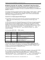
No additions to PLC program are needed if OMRONETH Server is used in a poll (normal)
mode, i.e. the Server sends read or write FINS command to PLC and PLC responds with
corresponding response. The OMRONETH Server supports also “unsolicited” data from
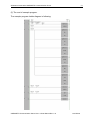
PLC – in this case some additions in PLC program are needed – see Example program
for sending “unsolicited” data from PLC section below in this manual.
Ethernet Unit configuration example for CV-series
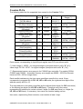
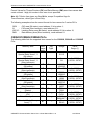
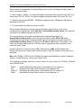
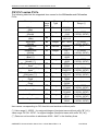
The following is a simple example of OMRON CV-series Ethernet Unit System Setup
configuration in most common case (see also "SYSMAC CV-series Ethernet System
Manual” pages 25 and 26).
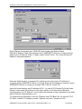
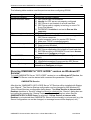
The Ethernet Unit system setup values are stored from the first byte in the OMRON PLC
system setup area. The following settings are important to establish communication
between OMRONETH Server and OMRON PLC with Ethernet Unit installed:
-
-
-
-
Mode Setting, Bit 00 (IP Address Setting) is equal to 0; in this case the node number
setting rotary switch (on the front panel of the Unit) is used as the node number in the
IP address of this Unit;
Mode Setting, Bits 02 and 03 (IP Address Conversion) is equal to 00 or 01; in this
case the automatic conversion will be done: the Unit’s IP address will be generated
automatically from the FINS node number and the IP address table will not be used;
Mode Setting, Bit 04 (FINS UDP Port Number Designation) is equal to 0; in this case
the UDP port number default value 9600 is used;
Local IP Address - set the IP address for the Ethernet Unit; set only the most
significant 3 bytes (octets) of the address in the local IP address setting (e.g.
199.52.260.) - the node number set on the rotary switches on the front panel of the
Unit will be automatically input as the host number in the fourth byte (octet) of the local
IP address;
Subnet Mask - set the subnet mask if system is running using subnetworks; if no
subnet mask is set (default), then subnet mask will be set automatically (usually to
FFFFFF00) depending on the local IP address setting.
OMRONETH Communication Server Ver 2.x User Manual Rev 1.12
1701XM112