1
INSTALLATION AND
OPERATION MANUAL
HS-6N, HS-12N
6/12-Channel High Speed Data Modules
Megaplex-2100/2104 Version 12, Megaplex-4100 Version 1.2
Innovative Access Solutions
HS-6N, HS-12N
6/12-Channel High Speed Data Modules
Megaplex-2100/2104 Version 12, Megaplex-4100 Version 1.2
Installation and Operation Manual
Notice
This manual contains information that is proprietary to RAD Data Communications Ltd. ("RAD").
No part of this publication may be reproduced in any form whatsoever without prior written
approval by RAD Data Communications.
Right, title and interest, all information, copyrights, patents, know-how, trade secrets and other
intellectual property or other proprietary rights relating to this manual and to the HS-6N, HS-12N
and any software components contained therein are proprietary products of RAD protected
under international copyright law and shall be and remain solely with RAD.
HS-6N, HS-12N is a registered trademark of RAD. No right, license, or interest to such trademark
is granted hereunder, and you agree that no such right, license, or interest shall be asserted by
you with respect to such trademark.
You shall not copy, reverse compile or reverse assemble all or any portion of the Manual or the
HS-6N, HS-12N. You are prohibited from, and shall not, directly or indirectly, develop, market,
distribute, license, or sell any product that supports substantially similar functionality as the HS6N, HS-12N, based on or derived in any way from the HS-6N, HS-12N. Your undertaking in this
paragraph shall survive the termination of this Agreement.
This Agreement is effective upon your opening of the HS-6N, HS-12N package and shall continue
until terminated. RAD may terminate this Agreement upon the breach by you of any term hereof.
Upon such termination by RAD, you agree to return to RAD the HS-6N, HS-12N and all copies
and portions thereof.
For further information contact RAD at the address below or contact your local distributor.
International Headquarters
RAD Data Communications Ltd.
North America Headquarters
RAD Data Communications Inc.
24 Raoul Wallenberg Street
Tel Aviv 69719, Israel
Tel: 972-3-6458181
Fax: 972-3-6498250, 6474436
E-mail: [email protected]
900 Corporate Drive
Mahwah, NJ 07430, USA
Tel: (201) 5291100, Toll free: 1-800-4447234
Fax: (201) 5295777
E-mail: [email protected]
© 1988–2007 RAD Data Communications Ltd.
Publication No. 764-248-10/07
Quick Start Guide
If you are familiar with the HS-6N and HS-12N modules, use this guide to prepare
the module for operation.
1.
Preparation for Operation
Insert the module in the prescribed I/O slot.
Connect the prescribed cables to the module CH connectors, in accordance with
the site installation plan.
2.
Configuration Procedure
To configure the desired HS-6N or HS-12N channel in the MP-2100/2104 chassis,
use the command:
DEF CH SS CC
where SS is the slot number, and CC is the channel number (1 to 6 for HS-6N,
and 1 to 12 for HS-12N).
To configure the desired HS-6N or HS-12N channel in the MP-4100 chassis, use
the Configuration>Physical Ports>I/O screen.
Configuration parameters and the range of values are listed in the following table.
Parameter
Connect*
Admin Status**
Rate
Range of Values
YES
NO
UP
DOWN
nx64kbps or nx56kbps, where:
n = 1 to 31 for E1 links
n = 1 to 24 for T1 links
RS-232 interface: only 64 kbps
DCE
Clock Mode
EXTERNAL DCE
DTE
HS-6N, HS-12N
MP-2100/2104 Ver. 12, MP-4100 Ver. 1.2
Configuration Procedure
1
Quick Start Guide
Installation and Operation Manual
Parameter
Range of Values
CTS
ON
RTS
FIFO Size
AUTOMATIC
16 BITS
30 BITS
52 BITS
72 BITS
NONE
BRD SRC CH*
EX1 to EX6 (HS-6N)
EX1 to EX12 (HS-12N)
Operation Mode
BI-DIR
UNI-BRD TX
UNI-BRD RX
BID-BRD RX*
BID-BRD RING*
ML Slot*
IO-1 up to the maximum
supported by the chassis
ML Channel*
EX1 up to the maximum
supported by the selected main
link module
Destination Slot**
CLX, IO-1 to IO-10, -
Destination Port**
1 to 8 for external ports
1 to 63 (1 to 84) for internal
(virtual) PDH ports
NONE
N/A
Map Type
USER
SEQUENCE
Start TS
N/A
1 to 31 for E1 links
1 to 24 for T1 links
* MP-2100/2104 only
** MP-4100 only
2
Configuration Procedure
HS-6N, HS-12N
MP-2100/2104 Ver. 12, MP-4100 Ver. 1.2
Installation and Operation Manual
3.
Quick Start Guide
Assigning Timeslots
Assign the uplink bandwidth to each connected channel as follows:
HS-6N, HS-12N
•
When using the BI-DIR, UNI-BRD TX or BID-BRD RING mode in the module
installed in the MP-2100/2104 chassis, use the DEF TS command as explained
in the Megaplex-2100/2104 Installation and Operation Manual. For the
module installed in the MP-4100 chassis, use the Configuration>System>TS
Assignment screen.
•
When using the UNI-BRD RX or BID-BRD RX mode in the module installed in
the MP-2100/2104 chassis, timeslot assignment for the receive direction is
made using the dedicated routing fields of the DEF CH command. For the
module installed in the MP-4100 chassis, use the Configuration>Physical
ports>IO screen.
MP-2100/2104 Ver. 12, MP-4100 Ver. 1.2
Assigning Timeslots
3
Quick Start Guide
4
Assigning Timeslots
Installation and Operation Manual
HS-6N, HS-12N
MP-2100/2104 Ver. 12, MP-4100 Ver. 1.2
Contents
Chapter 1. Introduction
1.1
1.2
1.3
1.4
Overview....................................................................................................................1-1
Versions .................................................................................................................1-1
Main Features.........................................................................................................1-1
Typical Applications.................................................................................................1-3
Basic Applications ..............................................................................................1-3
Point-to-Multipoint Applications .........................................................................1-4
Physical Description .................................................................................................1-10
Functional Description..............................................................................................1-11
HS-12N Functional Block Diagram .........................................................................1-11
TDM Bus Interfaces...............................................................................................1-13
Routing Matrix ......................................................................................................1-13
Channel Interfaces ................................................................................................1-13
Interface Characteristics...................................................................................1-13
Interface Control Signals ..................................................................................1-13
Channel Timing Modes......................................................................................1-14
Timing Subsystem .................................................................................................1-14
Diagnostics...........................................................................................................1-14
BER Test Subsystem .........................................................................................1-15
Local Management Subsystem ..............................................................................1-15
Technical Specifications............................................................................................1-16
Chapter 2. Installation and Operation
2.1
2.2
2.3
Introduction...............................................................................................................2-1
Installing the Module in the Chassis............................................................................2-1
Connecting the Cables................................................................................................2-2
Chapter 3. Configuration
3.1
3.2
3.3
3.4
3.5
3.6
3.7
Introduction...............................................................................................................3-1
Configuration Sequence for the MP-2100/2104 Chassis..............................................3-1
Configuration Sequence for the MP-4100 Chassis.......................................................3-2
Configuration Parameters...........................................................................................3-3
Assigning Timeslots....................................................................................................3-6
Configuring Timeslots for Submultiplexing (MP-2100/2104 only)................................3-7
Displaying Status and Configuration Information ........................................................3-7
Chapter 4. Troubleshooting and Diagnostics
4.1
4.2
4.3
Diagnostics ................................................................................................................4-1
Local Loopback .......................................................................................................4-2
Remote Loopback ...................................................................................................4-2
Bit Error Rate Testing (BERT)...................................................................................4-3
Recommended Test Sequence.................................................................................4-4
Frequently Asked Questions .......................................................................................4-5
Technical Support ......................................................................................................4-5
Appendix A. Pinouts
HS-6N, HS-12N
MP-2100/2104 Ver. 12, MP-4100 Ver. 1.2
i
Table of Contents
ii
Installation and Operation Manual
HS-6N, HS-12N
MP-2100/2104 Ver. 12, MP-4100 Ver. 1.2
Chapter 1
Introduction
1.1
Overview
This manual describes the technical characteristics, applications, installation and
operation of the HS-6N and HS-12N 6/12 high-speed data modules for use in
Megaplex-2100, Megaplex-2104, and Megaplex-4100 integrated access
multiplexers.
Versions
The HS-6N and HS-12N modules can be ordered in the following versions, which
differ with respect to the type of channel interface:
•
Modules with V.11/RS-422 channel interfaces. These versions support user’s
equipment with RS-530, V.36/RS-449, and X.21 physical interfaces.
•
Modules with V.35 channel interfaces, for connection to user’s equipment
with V.35 interfaces.
•
Modules with RS-232 channel interfaces, for connection to user’s equipment
with RS-232 interfaces.
Each version is available in two models:
Note
•
HS-12N: module with 12 independent channels
•
HS-6N: module with 6 independent channels.
In this manual, the generic term Megaplex is used when the information is
applicable to all the three Megaplex chassis. The complete designation is used
only for information applicable to a specific equipment version.
Main Features
The HS-6N and HS-12N modules support 6 or 12 high-speed synchronous data
channels, respectively.
Each channel can be independently configured to operate at a data rate of n×56
or n×64 kbps, where n = 1 to 24 when the channel is routed to a T1 link, and 1
to 31 (that is, maximum 1984 kbps) when the channel is routed to an E1 link.
Note
HS-6N, HS-12N
Modules with RS-232 interfaces support only 64 kbps.
MP-2100/2104 Ver. 12, MP-4100 Ver. 1.2
Overview
1-1
Chapter 1 Introduction
Installation and Operation Manual
Data rates are independently selectable for each channel. The only restrictions
are as follows:
•
The combined data rates of a pair of consecutive channels (i.e., 1 and 2;
3 and 4; etc.) cannot exceed 1984 kbps
•
You can operate the two channels of a pair at rates that are multiples of the
same basic rate (56 or 64 kbps), or at multiples of different basic rates.
However, in the latter case configure the second (even-numbered) channel of
a pair to operate at a multiple of 64 kbps, and configure the first
(odd-numbered) channel to operate at a multiple of 56 kbps.
In addition to the normal full-duplex (bidirectional) mode, HS-6N, HS-12N support
additional transmission modes, which enable point-to-multipoint communication:
•
Unidirectional (simplex) transmission, where each channel can be configured
either to receive (unidirectional RX) or transmit (unidirectional TX).
•
Bidirectional broadcast (half-duplex) communication, suitable for polled
applications. In this mode, a channel can either transmit or receive, but not
both simultaneously (the direction of transmission is determined by the state
of the local RTS line). This mode is supported only by the MP-2100 chassis.
•
Bidirectional broadcast ring mode that supports the Megaplex E1/T1 ring
topologies, and therefore combines the rapid response of master/slave
polling with the resiliency of the ring topology. To increase bandwidth
utilization efficiency in this mode, the HS-6N, HS-12N modules can also
perform submultiplexing, by allowing several low-rate (64 kbps) channels to
access the same main link timeslot. This mode is supported only by the
MP-2100 chassis.
For a description of these modes, see the Megaplex-2100/2104 Installation and
Operation Manual.
The timing mode of each channel can be configured to either DCE, external DCE
or DTE timing modes. The external DCE mode is used for tail-end applications,
whereas the DTE mode enables using an external clock source in applications that
require connecting to a data line provided by a data carrier service (for example,
DDS or Kilostream), with the external clock available as a system nodal timing
source.
The operating mode of each channel is independently selectable, using the
Megaplex management system or a supervision terminal.
The module has extensive diagnostics capabilities that reduce downtime to a
minimum. These capabilities include a comprehensive self-test initiated upon
power-on, local and remote loopbacks. The MP-2100/2104 chassis also supports
BER testing using an on-board test subsystem.
The module channels are terminated on 68-pin SCSI-4 female connectors. Each
connector contains three channels, and therefore HS-6N has two connectors,
and HS-12N has four connectors. Adapter cables, available upon order, are
offered by RAD to split each module connector into three separate channel
interfaces with standard connectors.
1-2
Overview
HS-6N, HS-12N
MP-2100/2104 Ver. 12, MP-4100 Ver. 1.2
Installation and Operation Manual
Chapter 1 Introduction
Typical Applications
Basic Applications
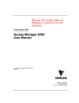
Figure 1-1 illustrates a HS-12N application that provides a large number of users
with flexible access to an SDH/SONET network. The total number of data channels
available in one fully equipped Megaplex-2100 unit is 120, where each channel
can operate at any data rate within the range supported by HS-12N.
Server
512 kbps
37X5
HS-12N
Modules
256 kbps
SDH/SONET
Network
E1/T1
DDS
Network
..
.
Up to 120
n x 56/64 kbps
Channels
ADM
384 kbps
..
.
Kilomux
Megaplex
64 kbps
Terminal
Figure 1-1. Typical HS-12N Application – Connecting 120 Data Channels to SDH/SONET Network
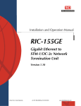
Figure 1-2 shows another application that enables users at several remote sites,
e.g., branch offices, to connect to data equipment or other users at a central site
(company headquarters) through a single HS-12N module.
HS-2
..
.
Megaplex
Up to 12
n x 56/64 kbps
Channels
HS-6N
..
.
..
..
.
E1/T1 or IP
Network
Megaplex
Megaplex
..
.
HS-QN
Megaplex
Figure 1-2. HS-12N at Central Site Serving Multiple Remote Sites
HS-6N, HS-12N
MP-2100/2104 Ver. 12, MP-4100 Ver. 1.2
Overview
1-3
Chapter 1 Introduction
Installation and Operation Manual
Point-to-Multipoint Applications
Unidirectional Broadcast Mode Applications
The unidirectional broadcast mode enables a user at a central location to send
data to multiple users connected to remote Megaplex units (simplex
communication), while using only the number of timeslots needed to support the
desired data rate.
In this mode, any message is simultaneously received by all the unidirectional
users, but none of them can send back data to the originator. This capability is
achieved by separating the handling of the receive and transmit paths for the
timeslots assigned for the unidirectional channels, as shown by the dashed lines
within the Megaplex units in Figure 1-3.
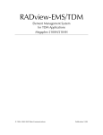
Figure 1-3 shows a network that uses the unidirectional broadcast mode to
distribute data from a central location (A) to several remote locations (B, C, D,
etc.). In Figure 1-3, the user at the central location (A) is connected to an
HS-12N channel configured for operation in the unidirectional transmit mode. The
channels of the remote users (at locations B, C, D) are configured for the
unidirectional receive mode.
Location D
HS-12N
(UNI-BRD RX)
Location A
HS-12N
(UNI-BRD TX)
Megaplex
Port 1
Location C
Port 2
HS-12N
(UNI-BRD RX)
Location B
Megaplex
Port 1 Port 2
Megaplex
Megaplex
HS-12N
(UNI-BRD RX)
User's Equipment
(Receive Only)
Figure 1-3. Typical Unidirectional Broadcast Application
At location A, the timeslots assigned to the user is routed to two main link ports
of the Megaplex unit, and can be inserted in timeslots with different numbers.
For simplicity, first the path to the user at location D is described:
•
1-4
Overview
In the forward path (from location A to D), the timeslots assigned to the
HS-12N channel configured for unidirectional transmit operation are routed
through the desired timeslots of port 1 to the Megaplex unit at location D.
HS-6N, HS-12N
MP-2100/2104 Ver. 12, MP-4100 Ver. 1.2
Installation and Operation Manual
Chapter 1 Introduction
At location D, the timeslots are routed to the receive path of the
unidirectional receive HS-12N channel. Therefore, the user D receives data
sent by user A.
•
In the reverse path (from location D to A), the timeslot is always
disconnected. Therefore, the user D cannot transmit data to user A.
The path to the users B and C is as follows:
•
In the forward path (from location A to B, C, etc.), the timeslots assigned to
the HS-12N channel configured for unidirectional transmit operation are
routed through the desired timeslot of port 2 to the Megaplex at location B.
At location B, the timeslots received at port 1 are routed as follows:
To the receive path of user B, configured for unidirectional receive mode
To the desired timeslots of port 2 (bypassing), which are connected to
the Megaplex at location C.
Therefore, the transmit signal of user A is relayed to the following units, and
the users at locations B and C receive data sent by user A.
The timeslots can be connected in parallel to any number of channels.
Note
•
In the reverse path (to location A), the timeslots are always bypassed from
port 2 to port 1, en route to location A.
To prevent interference from the unidirectional channel, its transmit path is
always disconnected from the main link timeslots (at location B, no
information is inserted in the timeslot bypassed from port 2 to port 1), and
user B cannot transmit data to any other user. The same is true for the user
at location C.
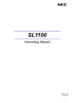
Figure 1-4 shows another network configuration, which enables regular (full
duplex, or bidirectional) communication between two users (the users at
locations A and C), and in addition enables monitoring the data sent by the user
A at location B.
Location A
Location C
HS-12N
(BI-DIR)
HS-12N
(BI-DIR)
Location B
Megaplex
Megaplex
Megaplex
HS-12N
(UNI-BRD RX)
User's Equipment
(Receive Only)
Figure 1-4. Typical Unidirectional Receive Application
For this configuration, the users A and C are configured as regular users, and only
the user at location B is configured for unidirectional receive operation.
HS-6N, HS-12N
MP-2100/2104 Ver. 12, MP-4100 Ver. 1.2
Overview
1-5
Chapter 1 Introduction
Installation and Operation Manual
Bidirectional Broadcast Mode Applications
The bidirectional broadcast mode, used for chain topologies, enables a user at a
central location to communicate half-duplex with several users connected to remote
Megaplex units, as needed, for example, to use polling. Figure 1-5 shows a network
topology using the bidirectional broadcast capability.
Note
The bidirectional broadcast mode is not available for the module operating in the
Megaplex-4100 chassis.
Location A
Port 2
Port 1
Location B
Location C
Location D
HS-12N
(BI-DIR)
Port 1
Link C
Link B
Link A
RX
TX
Port 2
Port 1
RX
TX
Port 2
HS-12N
(BID-BRD RX)
HS-12N
(BID-BRD RX)
Port 1
Port 2
HS-12N
(BID-BRD RX)
Figure 1-5. Typical Bidirectional Broadcast Application
The broadcast capability is achieved by separating the handling of the receive and
transmit paths for the timeslots assigned for the broadcast channels, as shown
by the dashed lines within the Megaplex units in Figure 1-5.
The user at the central location (the master in a polling application) is configured
to use the regular (bidirectional) mode. The other users (the slaves in a polling
application) are configured to use the bidirectional broadcast receive (BID BRD
RX) mode: this mode is similar to the unidirectional receive mode, except that at
any time only one of these users can transmit to (and be received by) user A, as
needed in polling applications.
In the application shown in Figure 1-5, the handling of the signals generated by user
A is similar to that for the unidirectional transmit mode described above. The
difference is that each broadcast user can insert its signal in the receive timeslots
that reach user A (instead of the signal bypassed from the other link). The change in
routing is controlled by the RTS signal in the data connector of the HS-12N module:
1-6
•
When the RTS signal is not active (idle state), the receive timeslots are
bypassed from port 2 to port 1, and continue toward user A.
•
When the RTS signal is asserted, the receive timeslot of port 2 is
disconnected from port 1, and the transmit path of the local broadcast user
is connected to port 1.
Overview
HS-6N, HS-12N
MP-2100/2104 Ver. 12, MP-4100 Ver. 1.2
Installation and Operation Manual
Chapter 1 Introduction
Thus, user A can request any user to answer, and that user can assert its RTS line
and thus connect to user A. At any time, only one user may transmit toward user A
(if more than one user transmits, only the user closest to location A will actually be
received).
When using the bidirectional broadcast receive mode, it is necessary to instruct
each main link port how to handle the traffic flow and signaling information. This is
performed by defining the timeslot type, as part of the DEF TS command (see
Megaplex-2100/2104 Installation and Operation Manual).
Bidirectional Broadcast Ring Mode Applications
The bidirectional broadcast mode, used for E1 and T1 ring topologies, provides
capabilities similar to those described above while taking advantage of the resiliency
of the E1 and T1 ring topology (see general description of the E1/T1 ring topology in
the Megaplex-21004 Installation and Operation Manual). In addition, this mode
improves the response time of the master/slave polling.
Note
The bidirectional broadcast mode is not available for the module operating in the
Megaplex-4100 chassis.
Figure 1-6 shows a network topology that uses the bidirectional broadcast ring
capability.
Master
P
S
RX
P
TX
TX
RX
P
TX
TX
RX
P
TX
RX
RX
P
TX
TX
RX
TX
HS-12N
RX
HS-12N
RX
S
TX
HS-12N
TX
S
HS-12N
RX
S
HS-12N
RX
S
BID-BRD RING
BID-BRD RING
BID-BRD RING
BID-BRD RING
BI-DIR
Legend:
P - Primary
S - Secondary
Figure 1-6. Typical Bidirectional Broadcast Ring Application
In the application shown in Figure 1-6, the HS-12N channel serving the master user
(located in the rightmost Megaplex unit) is configured to use the regular
(bidirectional) mode. The other users (the slaves in a polling application) are
configured to use the bidirectional broadcast ring (BID BRD RING) mode.
Note
Figure 1-6 through Figure 1-9 present only the route followed by the timeslots
carrying the payload of the HS-12N channel configured to bidirectional broadcast
ring mode.
Figure 1-7 shows the signal routing details within the Megaplex units with channels
configured to use the bidirectional broadcast ring:
•
Channel idle (RTS OFF):
The primary ring timeslots serving the channel are routed to the HS-12N
module for processing: the transmit timeslots are bypassed by means of
the internal routing matrix of the module (see Section 1.3), whereas the
HS-6N, HS-12N
MP-2100/2104 Ver. 12, MP-4100 Ver. 1.2
Overview
1-7
Chapter 1 Introduction
Installation and Operation Manual
receive timeslots are processed, and their payload is sent to the user’s
equipment through the corresponding channel interface.
All the secondary ring timeslots are bypassed within the main link
module, as explained in the Megaplex-2100 Installation and Operation
Manual.
•
Channel active (RTS ON): in this case, the routing within the HS-12N module
changes: the HS-12N routing matrix now inserts the payload received from
the user’s equipment into the channel transmit timeslots. All the secondary
ring timeslots are bypassed within the main link module.
The routing described above makes the primary ring completely transparent to all
the timeslots assigned to other payload. The only difference is in the routing of
the timeslots assigned to the local channel configured to use the bidirectional
broadcast ring:
•
When the channel is idle, these timeslots are transparently transferred
•
When the channel is active, its payload is inserted within these timeslots.
RX
TX
RX
S
P
TX
S
TX
RX
HS-12N
HS-12N
RX
RM
RM
To User
To User
Routing when Channel is Idle (RTS is OFF)
TX
P
Routing when Channel is Active (RTS is ON)
Figure 1-7. Signal Routing in the Bidirectional Broadcast Ring Mode
Figure 1-8 shows the signal flow when a fault occurs on the primary ring, and
Figure 1-9 shows the routing details within the Megaplex units.
Comparing Figure 1-9 to Figure 1-7 shows that under fault conditions, the internal
routing matrix directs the payload to the operational ring, while ignoring data
received from the faulty ring. Ring functionality is thus retained, both with respect
to the HS-12N channel and the timeslots assigned to other users.
1-8
Overview
HS-6N, HS-12N
MP-2100/2104 Ver. 12, MP-4100 Ver. 1.2
Installation and Operation Manual
Chapter 1 Introduction
Master
TX
RX
P
TX
TX
RX
P
TX
RX
RX
TX
HS-12N
HS-12N
RX
RX
S
P
TX
TX
RX
S
TX
TX
RX
RX
HS-12N
P
TX
S
HS-12N
RX
S
HS-12N
P
S
Legend:
P - Primary
S - Secondary
Figure 1-8. Signal Flow in Bidirectional Broadcast Ring Application during Primary Ring Fault
RX
TX
RX
S
P
TX
S
P
TX
RX
HS-12N
HS-12N
RX
RM
RM
To User
To User
Primary Ring Fault – Channel Idle (RTS OFF)
RX
Primary Ring Fault – Channel Active (RTS ON)
RX
TX
S
P
TX
TX
S
TX
RX
HS-12N
HS-12N
RX
RM
RM
To User
To User
Secondary Ring Fault – Channel Idle (RTS OFF)
TX
P
Secondary Ring Fault – Channel Active (RTS ON)
Figure 1-9. Signal Routing in the Bidirectional Broadcast Ring Mode during Ring Faults
HS-6N, HS-12N
MP-2100/2104 Ver. 12, MP-4100 Ver. 1.2
Overview
1-9
Chapter 1 Introduction
Installation and Operation Manual
Submultiplexing in Bidirectional Broadcast Ring Applications
The HS-6N, HS-12N offers a special submultiplexing mode, which reduces the
number of timeslots needed on the main links, by enabling several channels to
share the same main link timeslots.
Access conflicts are prevented as long as the polling regime enforced by the
user’s application is strictly observed: the application must ensure orderly access
to the communication links, one channel at a time, while allowing sufficient time
for the remote users to respond to polling on any given channel.
When these conditions are met, the user can configure any group of channels to
share one or more main link timeslots. For this purpose, it is necessary to
connect only one channel in the group to the desired timeslot; the other
channels must be associated with the connected channel (by specifying its port
number on the module).
The routing needed to connect any channel in the group to the timeslot assigned
to the group, is performed by the internal cross-connect matrix of the module
(see Section 1.3). The active channel is selected in accordance with the state of
its RTS signal. Note however that at any time only one channel in each group can
assert its RTS signal: if an additional channel asserts its RTS while another
channel is already connected to the timeslot, the last channel that asserts the
RTS line will be active.
The number of channels in a group is not restricted (up to the maximum number
of channels on the module); moreover, several groups may also be formed, by
associating the desired channels.
1.2
Physical Description
HS-6N and HS-12N are 4U-high modules that occupy one I/O slot in the Megaplex
chassis. All the functional parameters of the modules are determined by software.
The panels of the HS-6N and HS-12N modules include only the channel interface
connectors. Figure 1-10 shows typical module panels. The module version and
interface type also appear on the module panel.
1-10
Physical Description
HS-6N, HS-12N
MP-2100/2104 Ver. 12, MP-4100 Ver. 1.2
Installation and Operation Manual
HS-12/N
V.35
CH
4-6
Chapter 1 Introduction
HS-6/N
V.35
CH
1-3
CH
4-6
HS-12/N
RS-422
CH
1-3
CH
4-6
CH
7-9
CH
1-3
HS-6/N
RS-422
CH
4-6
HS-12/N
RS-232
CH
1-3
CH
4-6
CH
7-9
HS-12N
HS-6N
HS-12N
Typical Panels for Modules
with V.35 Interface
CH
1-3
HS-6/N
RS-232
CH
4-6
CH
1-3
CH
7-9
HS-6N
HS-12N
Typical Panels for Modules
with RS-422 Interface
HS-6N
Typical Panels for Modules
with RS-232 Interface
Figure 1-10. HS-6N/HS-12N Module Panels
1.3
Functional Description
HS-12N Functional Block Diagram
The functional block diagram of the HS-12N module is shown in Figure 1-11. The
HS-6N is similar, except that it has only 6 channel interfaces.
The HS-12N module includes the following main subsystems:
HS-6N, HS-12N
•
TDM bus interfaces
•
Routing (cross-connect) matrix
•
Channel interfaces
•
Timing subsystem
•
Test subsystem
•
Local management subsystem.
MP-2100/2104 Ver. 12, MP-4100 Ver. 1.2
Functional Description
1-11
Chapter 1 Introduction
Installation and Operation Manual
HS-6N/HS-12N
Channel
Interface 1
(Port EX1)
.
.
.
TDM
Bus A
Interface
Channel
Interface 3
(Port EX3)
TDM
Bus B
Interface
Channel
Interface 4
(Port EX4)
.
.
.
HS-12N Only
TDM Bus H
TDM Bus G
TDM Bus B
TDM Bus A
.
.
.
Routing
Matrix
Channel
Interface 7
(Port EX7)
.
.
.
TDM
Bus G
Interface
Channel
Interface 10
(Port EX10)
.
.
.
CH. 10-12
Connector
Channel
Interface 12
(Port EX12)
Control
Management
Channel
CH. 7-9
Connector
Channel
Interface 9
(Port EX9)
TDM
Bus H
Interface
Main Clock
CH. 4-6
Connector
Channel
Interface 6
(Port EX6)
.
.
.
.
.
.
To CL
Module
CH. 1-3
Connector
Local
Management
Test
Subsystem
Clock Selection
Fallback Clock
Receive
Clock
Generator
Timing and
Clock Signals
Internal
Timing
Generator
.
.
.
.
Clock Signals
From Channels
Internal
Clock & Timing
Signals
Figure 1-11. Module HS-12N, Functional Block Diagram
1-12
Functional Description
HS-6N, HS-12N
MP-2100/2104 Ver. 12, MP-4100 Ver. 1.2
Installation and Operation Manual
Chapter 1 Introduction
TDM Bus Interfaces
The HS-6N, HS-12N module has eight independent TDM bus interfaces, one for
each Megaplex TDM bus. Each TDM bus interface is used to connect timeslots
from the corresponding bus to the internal routing matrix of the HS-6N, HS-12N
module, in accordance with the commands received from the CL module.
Routing Matrix
The HS-6N, HS-12N module includes a routing matrix that controls the routing of
the module channels to the desired Megaplex uplink ports, via the TDM buses.
The Megaplex system enables you to select the uplink port that will carry the data
applied to the HS-6N, HS-12N module channels. Moreover, you can select, for
each module channel, the uplink timeslots assigned to that channel in the
corresponding E1 or T1 uplink frame. User-controlled manual assignment allows
the routing of the bit stream generated by each local channel to any other
compatible Megaplex channel at the remote site, e.g., to another channel of a
high-speed module such as HS-703, HS-2, HS-12N, etc.
Matrix routing is controlled by the CL module, and enables connecting any TDM
bus timeslot to any channel. The routing matrix also supports:
•
Unidirectional routing of timeslots
•
Broadcasting from one timeslot to multiple destinations
•
Submultiplexing in the bidirectional broadcast ring mode.
Refer to the Applications section starting on page 1-4 for details.
Channel Interfaces
Interface Characteristics
The HS-12N module can be ordered with the following interface types:
•
V.35
•
RS-422/V.11, which can be converted by means of adapter cables to
V.36/RS-449, RS-530, or X.21 interfaces
•
RS-232.
Interface Control Signals
Each channel has local support for the CTS, RTS, DCD, and DSR lines:
HS-6N, HS-12N
•
The DSR line is always ON.
•
The CTS line can be configured to be always ON, or to track the RTS line. The
same selection must be made for all the channels.
•
The DCD line is constantly ON, except when communications are not possible
because of loss of frame synchronization.
MP-2100/2104 Ver. 12, MP-4100 Ver. 1.2
Functional Description
1-13
Chapter 1 Introduction
Installation and Operation Manual
Channel Timing Modes
Each HS-6N, HS-12N module channel supports three timing modes:
•
DCE timing: the HS-6N, HS-12N channel provides the clock signals to the DTE
connected to it. This mode is suitable for connecting equipment with DTE
interface to the HS-12N channel.
•
External DCE timing: the HS-6N, HS-12N channel provides the receive clock
signal to the user's DTE, and accepts an external transmit clock. In this mode,
the user’s equipment must use loopback timing, that is, its transmit timing
must be locked to the receive timing. This mode is suitable for tail-end
applications.
•
DTE timing: the HS-6N, HS-12N channel accepts the external transmit and
receive clock signals from the user's equipment. In this case, the
HS-6N, HS-12N channel can serve as the nodal timing source for the
Megaplex system. This mode is suitable for connections to a digital
transmission network, which has its own accurate timing source.
FIFO buffers are used in the receive and transmit path of each module channel,
to absorb timing variations. FIFO size can be individually configured for each
channel. The Megaplex system can automatically select the FIFO size in
accordance with the minimum necessary. When a longer buffer is desired, the
user can also manually select the FIFO size. The supported FIFO sizes are ±16
bits, ±30 bits, ±52 bits, and ±72 bits.
Timing Subsystem
The HS-6N, HS-12N module has an internal timing generator that receives the
nodal timing and clock signals from the Megaplex chassis and generates the
internal timing and clock signals needed for module operation.
The timing subsystem also generates clock signals locked to the timing of
channels operating in the DTE mode, which can be selected as sources for the
Megaplex nodal timing. Note that a channel can be serve as a timing source only
when its RTS line is active, and therefore channels used in the polling mode are
not suitable as nodal clock sources.
Diagnostics
The HS-6N, HS-12N modules include self-test upon power-up, and provides
additional testing and diagnostic functions that can be controlled by system
management. These capabilities enable to reduce downtime to a minimum. The
testing capabilities include:
1-14
•
Local loopback: the signal received by a module channel is looped back
toward the local equipment.
•
Remote loopback on the local channel: loopback toward the remote
equipment.
•
Bit error rate (BER) testing (MP-2100 only).
Functional Description
HS-6N, HS-12N
MP-2100/2104 Ver. 12, MP-4100 Ver. 1.2
Installation and Operation Manual
Chapter 1 Introduction
BER Test Subsystem
The BER test subsystem is used to check the transmission performance and
proper operation of the paths carrying the user’s payload on the link toward the
remote user without requiring any external test equipment.
The BER test subsystem comprises a test sequence generator that generates an
RJ-011 sequence, and a test sequence evaluator. The output and input of the BER
test subsystem are routed by the routing matrix.
During the test, the payload data is replaced by the sequence generated by the
test sequence generator. The transmitted data is returned to the test sequence
evaluator by a loopback activated somewhere along the signal path. The
evaluator synchronizes to the incoming sequence, and then compares the
received data, bit by bit, to the original data sequence and detects any difference
(bit error).
The test results are displayed as a number in the range of 0 (no errors detected
during the current measurement interval) through 65535. If the upper limit is
reached, the counter stops accumulating errors and retains this maximum value
until it is manually reset.
Error counts are accumulated starting from the first synchronization to the BER
test pattern, or from the last clearing (resetting) of the error counters. During
normal operation, no errors should be detected.
At any time, only one BER test can be performed on the HS-6N, HS-12N module.
Local Management Subsystem
The local management subsystem controls the operation of the various circuits
located on the HS-6N, HS-12N module and the activation of the various
diagnostic functions, in accordance with the commands received from the CL
module through the Megaplex management channel.
HS-6N, HS-12N
MP-2100/2104 Ver. 12, MP-4100 Ver. 1.2
Technical Specifications
1-15
Chapter 1 Introduction
Installation and Operation Manual
1.4
Number of
Channels
Channel
Characteristics
Technical Specifications
HS-6N
Six synchronous data channels
HS-12N
Twelve synchronous data channels
Electrical Interface
• V.35
• V.11/RS-422
• V.24/RS-232
Physical Interface
• V.35 (via adapter cable)
• V.36/RS-449, RS-530, or X.21 (via adapter
cables)
• RS-232 (via adapter cable)
Channel Data Rates
n×56 or n×64 kbps rates, independently
selectable per channel:
• E1: n = 1 to 31
• T1: n = 1 to 24
Note: For HS-6N/12N modules with RS-232
interfaces, the only supported rate is 64 kbps.
Timing Modes
Connectors
68-pin SCSI female connector per each 3 data
channels (2 connectors for HS-6N and 4
connectors for HS-12N)
DCE
HS-6N, HS-12N channel provides both RX and TX
clocks to the user’s DTE
External-DCE
HS-6N, HS-12N channel provides RX clock to
user while receiving TX clock from user. Used for
tail-end applications
DTE
HS-6N, HS-12N channel receives both RX and TX
clocks from the user’s DCE
Control Signals
• CTS follows RTS or is constantly ON,
soft-selectable (same setting for all channels)
• DCD constantly ON, except during sync loss
• DSR always ON
Power
Consumption
Configuration
1-16
HS-6N
Max. 5.5W
HS-12N
Max. 6.25W
Programmable via Megaplex system management
Technical Specifications
HS-6N, HS-12N
MP-2100/2104 Ver. 12, MP-4100 Ver. 1.2
Chapter 2
Installation and Operation
2.1
Introduction
This chapter provides installation and operation instructions for the
HS-6N, HS-12N modules.
The information presented in this chapter supplements the general Megaplex
installation, configuration and operation instructions contained in the
Megaplex-2100/2104 Installation and Operation Manual and Megaplex-4100
Installation and Operation Manual.
Warning
Before performing any internal settings, adjustment, maintenance, or repairs,
first disconnect all the cables from the module, and then remove the module
from the Megaplex enclosure.
No internal settings, adjustment, maintenance, and repairs may be performed by
either the operator or the user; such activities may be performed only by a skilled
technician who is aware of the hazards involved.
Always observe standard safety precautions during installation, operation, and
maintenance of this product.
Caution The HS-6N, HS-12N modules contain components sensitive to electrostatic
discharge (ESD). To prevent ESD damage, always hold the module by its sides,
and do not touch the module components or connectors.
2.2
Installing the Module in the Chassis
The HS-6N/12N module can be installed in an operating chassis (hot insertion).
For general installation procedures and safety instructions, refer to the
Megaplex-2100/2104 or Megaplex-4100 Installation and Operation Manual.
Insert the module in the prescribed I/O slot and fasten it with its two screws.
The module starts operating as soon as it is plugged into an operating Megaplex
enclosure.
HS-6N, HS-12N
MP-2100/2104 Ver. 12, MP-4100 Ver. 1.2
Installing the Module in the Chassis
2-1
Chapter 2 Installation and Operation
2.3
Installation and Operation Manual
Connecting the Cables
The user’s equipment is connected to HS-12N modules via 68-pin SCSI female
connectors designated CH. 1-3, CH. 4-6, CH. 7-9, CH. 10-12. For HS-6N modules,
only the CH. 1-3 and CH. 4-6 connectors are used.
RAD offers adapter cables for directly connecting user’s equipment with standard
connectors to the appropriate 68-pin SCSI connector located on the
HS-6N/12N module. Figure 2-1 shows a typical adapter cable, and Table 2-1
provides information on the adapter cables available from RAD.
CH-1
CH
-2
-3
CH
Figure 2-1. CBL-SCS68/3/X21/M Cable
Table 2-1. Adapter Cables Offered by RAD
Module Version
V.35
RS-422
RS-232
Adapter Cable
User’s Side Connectors
CBL-SCS68/3/V35/M
34-pin VAPL male connector
CBL-SCS68/3/530/M
25-pin D-type male connector
CBL-SCS68/3/X21/M
15-pin D-type male connector
CBL-SCS68/3/V36/M
37-pin D-type male connector
CBL-SCS68/3/V36/F
37-pin D-type female connector
CBL-SCS68/3/232/M
25-pin D-type male connector
To connect the cables:
1. Identify the cables intended for connection to each module connector and
connect them into the appropriate connectors.
2. When using any of the adapter cables, plug each channel connector at the
other end of the cable into the prescribed user’s equipment connector in
accordance with the site installation plan.
The pin assignment of the CH connectors and of the adapter cables is given in
Appendix A.
2-2
Connecting the Cables
HS-6N, HS-12N
MP-2100/2104 Ver. 12, MP-4100 Ver. 1.2
Chapter 3
Configuration
3.1
Introduction
This chapter provides configuration information for HS-6N/12N modules installed
in the Megaplex-2100/2104 or Megaplex-4100 chassis. For general instructions
and additional configuration procedures, refer to Megaplex-2100/2104
Installation and Operation Manual and Megaplex-4100 Installation and Operation
Manual, respectively.
The configuration is performed by means of the management system used to
control the Megaplex unit:
•
Supervision terminal or Telnet – refer to the Megaplex-2100/2104 or
Megaplex-4100 Installation and Operation Manual for instructions.
•
Web browser – refer to the Megaplex-4100 Installation and Operation Manual
for instructions.
•
Network management system, e.g., the RADview network management
system – refer to the RADview User's Manual for instructions.
3.2
Configuration Sequence for the MP-2100/2104
Chassis
To configure an HS-6N, HS-12N module and put it into service:
1. Add an HS-6N, HS-12N module not yet installed in the Megaplex-2100/2104
chassis to the database. This allows preconfiguring the module parameters,
so that the module will immediately start operating in the desired mode as
soon as it is installed in the enclosure. For the supervision terminal, use the
DEF SYS command.
2. Configure the HS-6N, HS-12N channel parameters:
To define the parameters of all the module channels on the supervision
terminal, type the command:
DEF CH SS *
To define the parameters of a desired channel on the supervision
terminal, type the command:
DEF CH SS CC
HS-6N, HS-12N
MP-2100/2104 Ver. 12, MP-4100 Ver. 1.2
3-1
Chapter 3 Configuration
Installation and Operation Manual
where SS is the slot number, and CC is the channel number (1 to 6 for
HS-6N and 1 to 12 for HS-12N). For the parameter description, see
Table 3-1.
3. When necessary, modify the system timing reference to use the receive clock
of a HS-6N, HS-12N port as timing reference. For the supervision terminal,
use the DEF SYS command (for instructions, refer to the
Megaplex-2100/2104 Installation and Operation Manual).
4. Assign timeslots as described in Section 3.5.
Note
Make sure to plan ahead the configuration sequence, because Megaplex
databases can be updated only after correctly completing the configuration
activities: any sanity error will prevent saving the changes to the database being
modified.
3.3
Configuration Sequence for the MP-4100
Chassis
To configure an HS-6N, HS-12N module and put it into service:
1. Add an HS-6N, HS-12N module not yet installed in the Megaplex-4100 chassis
to the database. This allows preconfiguring the module parameters, so that
the module will immediately start operating in the desired mode as soon as it
is installed in the enclosure.
For the supervision terminal, use the Configuration>System>Card Type
screen.
2. Configure the CLX or M8E1/M8T1 module port parameters (depending on the
HS-6N/12N module application). For the configuration procedure, refer to the
appropriate Installation and Operation Manual.
3. Configure the HS-6N, HS-12N port parameters. For the supervision terminal,
use the Configuration>Physical Ports>I/O screen.
4. When necessary, modify the system timing reference to use the receive clock
of a HS-6N, HS-12N port as timing reference. For the supervision terminal,
use the Configuration>System>Clock Source screen (for instructions, refer to
the Megaplex-4100 Installation and Operation Manual).
5. Configure the timeslot assignment of each module port, using the
Configuration>System>TS Assignment screen.
Note
3-2
Make sure to plan ahead the configuration sequence, because Megaplex-4100
databases can be updated only after correctly completing the configuration
activities: any sanity error will prevent saving the changes to the database being
modified.
HS-6N, HS-12N
MP-2100/2104 Ver. 12, MP-4100 Ver. 1.2
Installation and Operation Manual
3.4
Chapter 3 Configuration
Configuration Parameters
Each HS-6N, HS-12N channel (external port) can be independently configured in
accordance with the system requirements.
Table 3-1 explains the programmable parameters of the HS-12N channels, and
their ranges of values.
Table 3-1. Channel Parameters
Parameter
Function
Values
Connect
Determines whether the channel is connected
to the internal TDM buses of the Megaplex
chassis
NO
The channel is disconnected. You can
still program the desired parameters,
so the channel will be ready to
operate when needed.
YES
The channel is connected to a legacy
main link port, and can carry traffic.
(MP-2100
only)
Default: NO
Admin Status Used to enable/disable the flow of traffic
through the selected port
(MP-4100
only)
UP
The flow of traffic is enabled.
DOWN
The flow of traffic is disabled. This
state should be selected as long as
the port configuration has not yet
been completed, or when it is
necessary to stop traffic flow
through the port.
Default: DOWN
Rate
Specifies the data rate of this channel.
The data rate determines the number of
timeslots allocated to the channel on the
selected uplink. The data rate is shown both as
a multiple of a basic rate (56 or 64 kbps), and
as an absolute number in kbps. This
representation has the advantage that you can
see at a glance the required number of
timeslots.
The allowed range is n×56 kbps or
n×64 kbps, where n is 1 through 24 for a T1
link, and 1 through 31 for an E1 link.
For HS-6N/12N modules with RS-232
interfaces, the only supported rate is
64 kbps.
Default: 1x64 = 64 KBPS
When selecting the rate, take into consideration
the number of timeslots used by, or must be
reserved for, other channels using the same
uplink. Moreover, if an E1 link is used and the
framing method is G.732S, you must also
reserve one timeslot (timeslot 16) for signaling.
The total rate assigned to a pair of consecutive
channels, for example, 1 and 2, 3 and 4, etc.,
cannot exceed 1984 kbps (31 timeslots). In
addition, you cannot select a multiple of 64
kbps for the first (odd) channel of a pair, and a
multiple of 56 kbps for the even channel
HS-6N, HS-12N
MP-2100/2104 Ver. 12, MP-4100 Ver. 1.2
3-3
Chapter 3 Configuration
Installation and Operation Manual
Parameter
Function
Values
Clock Mode
DCE – The channel provides transmit and
receive
clocks to the user’s equipment.
For a description of channel timing modes, refer
to the corresponding Megaplex Installation and EXTERNAL DCE – The channel provides the
receive clock to the user’s DTE, and accepts
Operation Manual.
the transmit clock from the user’s
equipment.
Selects the clock mode used by the channel.
DTE – The channel accepts transmit and
receive clocks from the user’s equipment.
Default: DCE
CTS
Selects the state of the channel CTS line.
ON
The CTS line is continuously on.
You must make the same selection for all the
module channels
RTS
The CTS line tracks the state of the
local RTS line.
Default: ON
FIFO Size
Selects the size of the FIFO buffer used by the
channel.
In general, you should select AUTOMATIC. For
special applications that require longer buffers,
you may want to select manually one of the
supported FIFO sizes (±16 bits, ±30 bits, ±52
bits, or ±72 bits)
AUTOMATIC – Automatic selection of FIFO
size. The automatically selected value
depends on the channel data rate:
•
±16 bits for 64 kbps
•
±30 bits for 128 and 192 kbps
•
±52 bits for 256 through 320 kbps
•
±72 bits for 384 through 1536 kbps
•
±52 bits for 1600 through 1792 kbps
•
±30 bits for 1856 and 1920 kbps
•
±16 bits for 1984 kbps.
16 BITS, 30 BITS, 52 BITS, 72 BITS – Selects a
specific FIFO size: ±16 bits, ±30 bits, ±52
bits, or ±72 bits, respectively. Make sure to
select a value equal to, or exceeding, the
automatically selected value at the operating
data rate.
Default: AUTOMATIC
BRD SRC CH
(MP-2100
only)
Controls the use of submultiplexing, a function
supported in the BID-BRD RING mode.
NONE
Submultiplexing is disabled.
This is the only allowed selection
when the Operation Mode is not
configured as BID-BRD RING.
EX1 to
EX6 or
EX12
Submultiplexing is enabled, and
the configured channel is being
associated with the channel
selected in this field.
See configuration guidelines on page 3-7
Default: NONE
3-4
HS-6N, HS-12N
MP-2100/2104 Ver. 12, MP-4100 Ver. 1.2
Installation and Operation Manual
Chapter 3 Configuration
Parameter
Function
Values
Operation
Mode
Selects the operation mode
BI-DIR – Bidirectional (regular) mode.
UNI-BRD TX – Unidirectional broadcast
transmit mode.
UNI-BRD RX – Unidirectional broadcast
receive mode.
BID-BRD RX – Bidirectional broadcast
receive mode (MP-2100/2104 only)
BID-BRD RING – Bidirectional broadcast
mode for E1/T1 ring topologies
(MP-2100/2104 only)
Default: BI-DIR
ML Slot
(MP-2100
only)
Selects the I/O slot number of the destination
main link module
•
When using the BI-DIR, UNI-BRD RX,
BID-BRD RX, or BID-BRD RING modes,
you can select the desired I/O slot.
•
When using the UNI-BRD TX mode, this
field automatically changes to BRD, to
remind you that the destination port
must be selected using the DEF TS
command.
Default: IO-1
ML Channel
(MP-2100
only)
Selects the number of the main link port on the
selected destination main link module
•
When using the BI-DIR, UNI-BRD RX,
BID-BRD RX or BID-BRD RING mode, you
can select the desired external port
number. The supported range depends
on the number of external ports
available on the main link module
installed in the slot selected by the ML
Slot parameter.
•
When using the UNI-BRD TX mode, this
field automatically changes to BRD, to
remind you that the destination port
must be selected using the DEF TS
command.
Default: EX1
Destination
Slot
(MP-4100
only)
Specifies the module (I/O slot) to which the data The available selections are the CLX module
stream handled by the port is routed.
installed in the chassis, and I/O modules
IO-1 to IO-10.
Destination
Port
(MP-4100
only)
Specifies the port to which the data stream
handled by the port is routed.
Default: –
The available selections are 1 to 8 for
external ports, or 1 to 63 (1 to 84) for
internal (virtual) ports (actual range
depends on the destination module).
Default: –
HS-6N, HS-12N
MP-2100/2104 Ver. 12, MP-4100 Ver. 1.2
3-5
Chapter 3 Configuration
Installation and Operation Manual
Parameter
Function
Values
Map Type
Selects the timeslot mapping method when the
destination is a TDM main link or CLX port.
•
When using the BI-DIR, UNI-BRD TX or
BID-BRD RING mode for a module
installed in a MP-2100 chassis, this field
automatically changes to N/A, to remind
you that the destination must be
selected using the DEF TS command
•
When using the UNI-BRD RX or BID-BRD
RX mode, you can select the desired
mode:
For a module installed in a MP-4100 chassis,
this field appears only for the UNI-BRD RX
mode.
USER
You can select the desired
uplink timeslots on the
timeslot map.
SEQUENCE
The external port is
assigned consecutive
timeslots, starting with the
timeslot specified by means
of the Start TS parameter.
Default: N/A
Start TS
Selects the starting timeslot in the frame of the
destination TDM uplink port.
The allowed range is 1 to 31 for E1 ports, and
1 to 24 for T1 ports.
This parameter can be selected only when using
the SEQUENCE mapping mode; when using any
other mode, this field automatically changes to
N/A.
Default: N/A
3.5
Assigning Timeslots
After performing the configuration of the individual module channels, it is
necessary to assign the uplink bandwidth to each connected channel.
3-6
•
When using the BI-DIR, UNI-BRD TX or BID-BRD RING mode in the module
installed in the MP-2100/2104 chassis, use the DEF TS command as explained
in the Megaplex-2100/2104 Installation and Operation Manual. For the
module installed in the MP-4100 chassis, use the Configuration>System>TS
Assignment screen.
•
When using the UNI-BRD RX or BID-BRD RX mode in the module installed in
the MP-4100 chassis, timeslot assignment for the receive direction is made
using the dedicated routing fields of the DEF CH command. For the module
installed in the MP-4100 chassis, use the Configuration>Physical ports>IO
screen.
HS-6N, HS-12N
MP-2100/2104 Ver. 12, MP-4100 Ver. 1.2
Installation and Operation Manual
3.6
Chapter 3 Configuration
Configuring Timeslots for Submultiplexing
(MP-2100/2104 only)
When using submultiplexing, only one channel in a group is connected to the
main link, and therefore only that channel must be assigned a timeslot.
Example:
It is necessary to configure channels 1, 2, 3, 9 as a group using the timeslot
assigned to channel 1, and channels 6, 7, 8, 12 as another group using the
timeslot assigned to channel 7:
1. Make sure that all the channels (1, 2, 3, 6, 7, 8, 9, 12) are connected,
configured for 64 kbps, and their Operation Mode is BID-BRD RING.
2. Assign one timeslot to channel 1 and another timeslot to channel 7.
3. For channels 1 and 7, configure the BID-SRC CH parameter to NONE.
4. For channels 2, 3, 9, configure the BID-SRC CH parameter to EX1.
5. For channels 6, 8, 12, configure the BID-SRC CH parameter to EX7.
3.7
Displaying Status and Configuration
Information
The Megaplex-2100 user can read the HS-6N/12N status and configuration
information using the DSP ST CH command. For a general description of this
command, refer to Appendix F of the Megaplex-2100/2104 Installation and
Operation Manual.
The DSP ST CH command includes two sections:
•
Hardware Config/Status: displays the module interface type (V.35, RS-422, or
RS-232), and the state of the RTS (or CI) line of each channel at the time the
command has been received by the module.
•
Software Configuration: displays a data form similar to that displayed by the
DEF CH command, showing the current configuration of each channel. For a
description of the displayed parameters, refer to Table 3-1.
The Megaplex-4100 user can read the configuration on every port of the I/O
modules using the Configuration>Physical Ports>I/O menu. To display the
HS-6N/12N hardware status and RTS state information, use the
Monitoring>Physical Ports>I/O screen. For a general description of these menus,
refer to Chapter 4 of the Megaplex-4100 Installation and Operation Manual.
HS-6N, HS-12N
MP-2100/2104 Ver. 12, MP-4100 Ver. 1.2
3-7
Chapter 3 Configuration
3-8
Installation and Operation Manual
HS-6N, HS-12N
MP-2100/2104 Ver. 12, MP-4100 Ver. 1.2
Chapter 4
Troubleshooting and
Diagnostics
This chapter explains the specific diagnostic functions of the HS-6N and HS-12N
modules and provides troubleshooting information.
For a description of the alarm and configuration (“sanity”) error messages
generated by HS-6N, HS-12N modules, refer to Appendix B of the
Megaplex-2100/2104 Installation and Operation Manual or Chapter 5 of the
Megaplex-4100 Installation and Operation Manual.
The diagnostic information presented in this chapter supplements the general
diagnostics and troubleshooting information instructions contained in the
corresponding Megaplex Installation and Operation Manual.
4.1
Diagnostics
The HS-6N/12N modules have a complete set of tests and loopback that include:
•
Local loopback on each channel
•
Remote loopback on each channel
•
Bit error rate test (BERT) on each channel.
When a test or loopback is activated, the user can also specify the time it remains
active: the range is 1 through 30 minutes, in 1-minute steps. After the specified
time, the test or loopback is automatically deactivated, thereby reducing the
management workload during system troubleshooting. The default selection is
continuous connection, that is, the test or loopback remain active until canceled
by a user's command.
•
To activate a test in a HS-6N, HS-12N module installed in a MP-2100 chassis,
use the DEF TST (or DEF TEST) command, and then select the local/remote
loopback or BERT, as described in the Megaplex-2100/2104 Installation and
Operation Manual.
•
To activate a test in a HS-6N, HS-12N module installed in a MP-4100 chassis,
use the Mp4100>Diagnostics>Physical Ports>I/O menu, and then select the
local or remote loopback, as described in the Megaplex-4100 Installation and
Operation Manual.
The following sections describe the available diagnostic activities.
HS-6N, HS-12N
MP-2100/2104 Ver. 12, MP-4100 Ver. 1.2
Diagnostics
4-1
Chapter 4 Troubleshooting and Diagnostics
Installation and Operation Manual
Local Loopback
The local loopback is performed at the channel input, by returning the transmit
signal of the channel to the receive path. The transmit signal is still sent to the
remote Megaplex unit.
A typical local loopback signal path for a HS-12N module is shown in Figure 4-1.
.
.
User or
Test
Equipment
.
..
.
..
..
..
..
.
.
HS-12N
HS-12N
Local Unit
User or
Test
Equipment
Remote Unit
System
Management
Figure 4-1. Local Loopback, Signal Path
Remote Loopback
The remote loopback is performed at the channel output, by returning the receive
signal of the channel to the input of its transmit path. The receive signal is still
available to the local user.
A typical remote loopback signal path for a HS-12N module is shown in
Figure 4-2.
4-2
Diagnostics
HS-6N, HS-12N
MP-2100/2104 Ver. 12, MP-4100 Ver. 1.2
Installation and Operation Manual
Chapter 4 Troubleshooting and Diagnostics
.
.
User or
Test
Equipment
.
..
.
..
..
..
..
.
.
HS-12N
HS-12N
Local Unit
User or
Test
Equipment
Remote Unit
System
Management
Figure 4-2. Remote Loopback, Signal Path
Bit Error Rate Testing (BERT)
The BERT is used to check for proper data transmission through a selected
channel, and obtain a qualitative evaluation of data transmission without using
external test equipment. At any given time, BER testing can be performed on only
one channel of the HS-6N/12N module.
During this test, the local BER system is connected to the corresponding local
channel, as shown in Figure 4-3. To return the test pattern to the test sequence
evaluator, the user activates a loopback at the desired location.
HS-6N, HS-12N
MP-2100/2104 Ver. 12, MP-4100 Ver. 1.2
Diagnostics
4-3
Chapter 4 Troubleshooting and Diagnostics
Installation and Operation Manual
.
.
..
..
..
..
..
..
.
.
Test Sequence
Evaluator
Test Sequence
Generator
HS-12N
Remote Unit
Local Unit
I/O MODULES
I/O MODULES
HS-12N
System
Management
Figure 4-3. BERT Signal Path
The bit error rate is measured by applying an RJ-011 test sequence generated by
an on-board generator to the input of the transmit path. The transmitted data is
returned by means of a loopback somewhere along the data path (e.g., by
connecting a local or remote main link loopback) to the receive path of the
module, and routed to a test sequence evaluator.
Instead of using a loopback, it is also possible to activate the BERT at both ends
of the link, because the same data patterns are used at both ends. The evaluator
compares the received data, bit by bit, to the original data and detects any
difference (bit error). The output of the evaluator is sampled during module
polling, to check whether errors were detected in the interval between
consecutive pollings.
The user can read the accumulated test time and the number of errors detected
since the test has been started. For convenience, the user can also clear the
accumulated results without interrupting the test.
During the BERT, the channel is disconnected from the user data equipment.
Note
The BER test is not supported by the MP-4100 chassis.
Recommended Test Sequence
The loops available on the HS-6N/12N module provide a rapid and efficient way
to identify the general location of a fault at either in a HS-6N/12N module, or in
the external equipment or connections to channels.
4-4
Diagnostics
HS-6N, HS-12N
MP-2100/2104 Ver. 12, MP-4100 Ver. 1.2
Installation and Operation Manual
Note
Chapter 4 Troubleshooting and Diagnostics
When the problem is detected when a new connection is activated for the first
time, before starting the troubleshooting procedure described below thoroughly
check the timeslot allocation, the configuration of the two Megaplex units that
provide the new connection, and the configuration of the module and the
equipment connected to the module channel.
If a complaint is received from one of the users connected to a HS-6N/12N
module, first activate the HS-6N/12N local loopback at the side the complaint is
received from. The local user must receive its own signal. If the signal is not
received, the problem is at the local end:
•
Check the connections to the user equipment, or the user's equipment itself.
•
Replace the cable.
•
Replace the local HS-6N/12N module.
If the local subscriber receives its own signal when the local loopback is
connected, activate the remote loopback and repeat the check. You may also
perform BER testing, to confirm the proper operation of the transmission path.
If the remote loopback and BER test indicate the link operates normally, the
problem is at the remote end. To check, repeat the procedure on the remote
Megaplex unit.
4.2
Frequently Asked Questions
Q:
When installed in the MP-4100 chassis, do the HS-6N, HS-12N modules
operate exactly the same as when installed in the MP-2100/2104 chassis?
A:
Yes, they do. All the differences between the two module locations are
purely chassis/common logic related (command line vs menu interface,
main link vs CLX or I/O ports as timeslot destinations, etc.) The main
module-level difference is that the bidirectional broadcast modes (BID-BRD
RX and BID-BRD RING) are not available for the module operating in the
Megaplex-4100 chassis. Also, the MP-4100 chassis does not support the
BER test.
4.3
Technical Support
Technical support for this product can be obtained from the local distributor from
whom it was purchased.
For further information, please contact the RAD distributor nearest you or one of
RAD's offices worldwide. This information can be found at www.rad.com (offices
– About RAD > Worldwide Offices; distributors – Where to Buy > End Users).
HS-6N, HS-12N
MP-2100/2104 Ver. 12, MP-4100 Ver. 1.2
Technical Support
4-5
Chapter 4 Troubleshooting and Diagnostics
4-6
Technical Support
Installation and Operation Manual
HS-6N, HS-12N
MP-2100/2104 Ver. 12, MP-4100 Ver. 1.2
Appendix A
Pinouts
A.1
SCSI Connector Pinout
The user’s equipment is connected to HS-12N modules via 68-pin SCSI female
connectors designated CH. 1-3, CH. 4-6, CH. 7-9, CH. 10-12. For HS-6N modules,
only the CH. 1-3 and CH. 4-6 connectors are used.
Table A-1 lists the pin assignment of the CH connectors. Note that the pins in
actual use depend on the module version.
Table A-1. CH Connector, Pin Assignment
Channel Pin Designation
–
1,
4,
7,
10
2,
5,
8,
11
Function
Pin Designation
Function
1
F.G.
Frame Ground
35
S.G.
Signal Ground
2
RD(A)
Receive Data A
36
RD(B)
Receive Data B
3
TC(A)
Transmit Clock A
37
TC(B)
Transmit Clock B
4
RC(A)
Receive Clock A
38
RC(B)
Receive Clock B
5
ERC(A)
External Receive Clock A
39
ERC(B)
External Receive Clock B
6
ETC(A)
External Transmit Clock A
40
ETC(B)
External Transmit Clock B
7
TD(A)
Transmit Data A
41
TD(B)
Transmit Data B
8
CO(A)
Control Out A
42
CO(B)
Control Out B
9
DSR(A)
Data Set Ready A
43
DSR(B)
Data Set Ready B
10
DCD(A)
Data Carrier Detect A
44
DCD(B)
Data Carrier Detect B
11
CI(A)
Control In A
45
CI(B)
Control In B
12
F.G
Frame Ground
46
S.G
Signal Ground
13
RD(A)
Receive Data A
47
RD(B)
Receive Data B
14
TC(A)
Transmit Clock A
48
TC(B)
Transmit Clock B
15
RC(A)
Receive Clock A
49
RC(B)
Receive Clock B
16
ERC(A)
External Receive Clock A
50
ERC(B)
External Receive Clock B
17
ETC(A)
External Transmit Clock A
51
ETC(B)
External Transmit Clock B
18
TD(A)
Transmit Data A
52
TD(B)
Transmit Data B
19
CO(A)
Control Out A
53
CO(B)
Control Out B
20
DSR(A)
Data Set Ready A
54
DSR(B)
Data Set Ready B
21
DCD(A)
Data Carrier Detect A
55
DCD(B)
Data Carrier Detect B
22
CI(A)
Control In A
56
CI(B)
Control In B
23
F.G
Frame Ground
57
S.G
Signal Ground
HS-6N, HS-12N
MP-2100/2104 Ver. 12, MP-4100 Ver. 1.2
SCSI Connector Pinout
A-1
Appendix A Pinouts
Installation and Operation Manual
Table A-1. CH Connector, Pin Assignment (Cont.)
Channel Pin Designation
3,
6,
9,
12
Function
Pin Designation
Function
24
RD(A)
Receive Data A
58
RD(B)
Receive Data B
25
TC(A)
Transmit Clock A
59
TC(B)
Transmit Clock B
26
RC(A)
Receive Clock A
60
RC(B)
Receive Clock B
27
ERC(A)
External Receive Clock A
61
ERC(B)
External Receive Clock B
28
ETC(A)
External Transmit Clock A
62
ETC(B)
External Transmit Clock B
29
TD(A)
Transmit Data A
63
TD(B)
Transmit Data B
30
CO(A)
Control Out A
64
CO(B)
Control Out B
31
DSR(A)
Data Set Ready A
65
DSR(B)
Data Set Ready B
32
DCD(A)
Data Carrier Detect A
66
DCD(B)
Data Carrier Detect B
33
CI(A)
Control In A
67
CI(B)
Control In B
34
F.G
Frame Ground
68
S.G
Signal Ground
A.2
Adapter Cables
RAD offers adapter cables for directly connecting user’s equipment with standard
connectors to the appropriate 68-pin SCSI-4 connector located on the HS-6N/12N
module. Table A-2 provides information on the adapter cables available from RAD.
Wiring information on each cable is provided in the following sections.
Table A-2. Adapter Cables Offered by RAD
Module Version
V.35
RS-422
RS-232
Adapter Cable
User’s Side Connectors
CBL-SCS68/3/V35/M
34-pin VAPL male connector
CBL-SCS68/3/530/M
25-pin D-type male connector
CBL-SCS68/3/X21/M
15-pin D-type male connector
CBL-SCS68/3/V36/M
37-pin D-type male connector
CBL-SCS68/3/V36/F
37-pin D-type female connector
CBL-SCS68/3/232/M
25-pin D-type male connector
The user side of each cable is terminated in three connectors, designated CH-1,
CH-2, CH-3. The tables in the following sections list the pinout of each connector
on the HS-6N, HS-12N and user sides and indicate the number of HS-6N, HS-12N
channel corresponding to each pin.
A-2
Adapter Cables
HS-6N, HS-12N
MP-2100/2104 Ver. 12, MP-4100 Ver. 1.2
Installation and Operation Manual
Appendix A Pinouts
CBL-SCS68/3/V35/M Cable
Figure A-1 shows a general view of the CBL-SCS68/3/V35/M cable, and Table A-3
lists the cable wiring.
CH-1
CH2
-3
CH
Figure A-1. CBL-SCS68/3/V35/M Cable
Table A-3. CBL-SCS68/3/V35/M, Cable Wiring
Ch
1,
SCSI
Connector
Function
1
F.G.
Not Used
2
RD(A)
Receive Data A
3
TC(A)
4
Not Used
R
36 RD(B)
Receive Data B
Transmit Clock A
Y
37 TC(B)
Transmit Clock B
AA
RC(A)
Receive Clock A
V
38 RC(B)
Receive Clock B
X
5
ERC(A)
External Receive Clock A
BB
39 ERC(B)
External Receive Clock B
Z
6
ETC(A)
External Transmit Clock
A
U
40 ETC(B)
External Transmit Clock
B
W
7
TD(A)
Transmit Data A
P
41 TD(B)
Transmit Data B
S
CO
Control Out
D
42 –
Not Used
9
DSR
Data Set Ready
E
43 –
Not Used
10
DCD
Data Carrier Detect
F
44 –
Not Used
11
CI
Control In
C
45 –
Not Used
12
F.G
Frame Ground
A
46 S.G
Signal Ground
B
13
RD(A)
Receive Data A
R
47 RD(B)
Receive Data B
T
14
TC(A)
Transmit Clock A
Y
48 TC(B)
Transmit Clock B
AA
15
RC(A)
Receive Clock A
V
49 RC(B)
Receive Clock B
X
16
ERC(A)
External Receive Clock A
BB
50 ERC(B)
External Receive Clock B
Z
17
ETC(A)
External Transmit Clock
A
U
51 ETC(B)
External Transmit Clock
B
W
18
TD(A)
Transmit Data A
P
52 TD(B)
Transmit Data B
S
CO
Control Out
D
53 –
Not Used
20
DSR
Data Set Ready
E
54 –
Not Used
21
DCD
Data Carrier Detect
F
55 –
Not Used
22
CI
Control In
C
56 –
Not Used
23
F.G
Frame Ground
A
57 S.G
Signal Ground
10 8
2,
5,
8,
34-Pin
Connector
Function
35 S.G.
4,
7,
SCSI
34-Pin
Connector Connector
11 19
HS-6N, HS-12N
MP-2100/2104 Ver. 12, MP-4100 Ver. 1.2
Adapter Cables
T
B
A-3
Appendix A Pinouts
Installation and Operation Manual
Table A-3. CBL-SCS68/3/V35/M Cable Wiring (Cont.)
Ch
3,
SCSI
Connector
Function
24
RD(A)
Receive Data A
R
58 RD(B)
Receive Data B
25
TC(A)
Transmit Clock A
Y
59 TC(B)
Transmit Clock B
AA
26
RC(A)
Receive Clock A
V
60 RC(B)
Receive Clock B
X
27
ERC(A)
External Receive Clock A
BB
61 ERC(B)
External Receive Clock B
Z
28
ETC(A)
External Transmit Clock
A
U
62 ETC(B)
External Transmit Clock
B
W
29
TD(A)
Transmit Data A
P
63 TD(B)
Transmit Data B
S
CO
Control Out
D
64 –
Not Used
31
DSR
Data Set Ready
E
65 –
Not Used
32
DCD
Data Carrier Detect
F
66 –
Not Used
33
CI
Control In
C
67 –
Not Used
34
F.G
Frame Ground
A
68 S.G
Signal Ground
6,
9,
12 30
34-Pin
SCSI
Connector Connector
34-Pin
Connector
Function
T
B
CBL-SCS68/3/530/M Cable
Figure A-2 shows a general view of the CBL-SCS68/3/530/M cable, and Table A-4
lists the cable wiring.
CH-1
CH
-2
-3
CH
Figure A-2. CBL-SCS68/3/530/M Cable
Table A-4. CBL-SCS68/3/530/M Cable Wiring
SCSI
Connector
Function
1
F.G.
Not Used
2
RD(A)
Receive Data A
1,
3
TC(A)
4,
4
Ch
7,
10
A-4
25-Pin
SCSI
Connector Connector
Function
25-Pin
Connector
35 S.G.
Not Used
3
36 RD(B)
Receive Data B
16
Transmit Clock A
15
37 TC(B)
Transmit Clock B
12
RC(A)
Receive Clock A
17
38 RC(B)
Receive Clock B
9
5
ERC(A)
External Receive Clock A
20
39 ERC(B)
External Receive Clock B
23
6
ETC(A)
External Transmit Clock
A
24
40 ETC(B)
External Transmit Clock
B
11
Adapter Cables
HS-6N, HS-12N
MP-2100/2104 Ver. 12, MP-4100 Ver. 1.2
Installation and Operation Manual
Appendix A Pinouts
Table A-4. CBL-SCS68/3/530/M Cable Wiring (Cont.)
SCSI
Connector
Function
7
TD(A)
Transmit Data A
2
41 TD(B)
Transmit Data B
14
8
CO(A)
Control Out A
5
42 CO(B)
Control Out B
13
9
DSR(A)
Data Set Ready A
6
43 DSR(B)
Data Set Ready B
22
10
DCD(A)
Data Carrier Detect A
8
44 DCD(B)
Data Carrier Detect B
10
11
CI(A)
Control In A
4
45 CI(B)
Control In B
19
12
F.G
Frame Ground
1
46 S.G
Signal Ground
7
13
RD(A)
Receive Data A
3
47 RD(B)
Receive Data B
16
14
TC(A)
Transmit Clock A
15
48 TC(B)
Transmit Clock B
12
15
RC(A)
Receive Clock A
17
49 RC(B)
Receive Clock B
9
16
ERC(A)
External Receive Clock A
20
50 ERC(B)
External Receive Clock B
23
17
ETC(A)
External Transmit Clock
A
24
51 ETC(B)
External Transmit Clock
B
11
18
TD(A)
Transmit Data A
2
52 TD(B)
Transmit Data B
14
11 19
CO(A)
Control Out A
5
53 CO(B)
Control Out B
13
20
DSR(A)
Data Set Ready A
6
54 DSR(B)
Data Set Ready B
22
21
DCD(A)
Data Carrier Detect A
8
55 DCD(B)
Data Carrier Detect B
10
22
CI(A)
Control In A
4
56 CI(B)
Control In B
19
23
F.G
Frame Ground
1
57 S.G
Signal Ground
7
24
RD(A)
Receive Data A
3
58 RD(B)
Receive Data B
16
25
TC(A)
Transmit Clock A
15
59 TC(B)
Transmit Clock B
12
26
RC(A)
Receive Clock A
17
60 RC(B)
Receive Clock B
9
27
ERC(A)
External Receive Clock A
20
61 ERC(B)
External Receive Clock B
23
28
ETC(A)
External Transmit Clock
A
24
62 ETC(B)
External Transmit Clock
B
11
29
TD(A)
Transmit Data A
2
63 TD(B)
Transmit Data B
14
12 30
CO(A)
Control Out A
5
64 CO(B)
Control Out B
13
31
DSR(A)
Data Set Ready A
6
65 DSR(B)
Data Set Ready B
22
32
DCD(A)
Data Carrier Detect A
8
66 DCD(B)
Data Carrier Detect B
10
33
CI(A)
Control In A
4
67 CI(B)
Control In B
19
34
F.G
Frame Ground
1
68 S.G
Signal Ground
Ch
2,
5,
8,
3,
6,
9,
HS-6N, HS-12N
25-Pin
SCSI
Connector Connector
MP-2100/2104 Ver. 12, MP-4100 Ver. 1.2
25-Pin
Connector
Function
Adapter Cables
7
A-5
Appendix A Pinouts
Installation and Operation Manual
CBL-SCS68/3/X21/M Cable
Figure A-3 shows a general view of the CBL-SCS68/3/X21/M cable, and Table A-5
lists the cable wiring.
CH-1
CH
-2
-3
CH
Figure A-3. CBL-SCS68/3/X21/M Cable, General View
Table A-5. CBL-SCS68/3/X21/M Cable Wiring
Ch
1,
4,
7,
10
A-6
SCSI
Connector
Function
1
F.G.
Not Used
2
RD(A)
Receive Data A
3
TC(A)
Transmit Clock A
4
–
Not Used
5
ETC(A)
External Transmit Clock
A
6
ETC(A)
7
15-Pin
SCSI
Connector Connector
Function
15-Pin
Connector
35 S.G.
Not Used
4
36 RD(B)
Receive Data B
11
6
37 TC(B)
Transmit Clock B
13
38 –
Not Used
7
39 ETC(B)
External Transmit Clock
B
14
External Transmit Clock
A
7
40 ETC(B)
External Transmit Clock
B
14
TD(A)
Transmit Data A
2
41 TD(B)
Transmit Data B
8
–
Not Used
42 –
Not Used
9
–
Not Used
43 –
Not Used
10
DCD(A)
Data Carrier Detect A
5
44 DCD(B)
Data Carrier Detect B
12
11
CI(A)
Control In A
3
45 CI(B)
Control In B
10
12
F.G
Frame Ground
1
46 S.G
Signal Ground
Adapter Cables
HS-6N, HS-12N
9
8
MP-2100/2104 Ver. 12, MP-4100 Ver. 1.2
Installation and Operation Manual
Appendix A Pinouts
Table A-5. CBL-SCS68/3/X21/M Cable Wiring (Cont.)
Ch
2,
5,
8,
11
3,
6,
9,
12
SCSI
Connector
Function
15-Pin
SCSI
Connector Connector
15-Pin
Connector
13
RD(A)
Receive Data A
4
47 RD(B)
Receive Data B
11
14
TC(A)
Transmit Clock A
6
48 TC(B)
Transmit Clock B
13
15
–
Not Used
49 –
Not Used
16
ETC(A)
External Transmit Clock
A
7
50 ETC(B)
External Transmit Clock
B
14
17
ETC(A)
External Transmit Clock
A
7
51 ETC(B)
External Transmit Clock
B
14
18
TD(A)
Transmit Data A
2
52 TD(B)
Transmit Data B
19
–
Not Used
53 –
Not Used
20
–
Not Used
54 –
Not Used
21
DCD(A)
Data Carrier Detect A
5
55 DCD(B)
Data Carrier Detect B
12
22
CI(A)
Control In A
3
56 CI(B)
Control In B
10
23
F.G
Frame Ground
1
57 S.G
Signal Ground
8
24
RD(A)
Receive Data A
4
58 RD(B)
Receive Data B
11
25
TC(A)
Transmit Clock A
6
59 TC(B)
Transmit Clock B
13
26
–
Not Used
60 –
Not Used
27
ETC(A)
External Transmit Clock
A
7
61 ETC(B)
External Transmit Clock
B
14
28
ETC(A)
External Transmit Clock
A
7
62 ETC(B)
External Transmit Clock
B
14
29
TD(A)
Transmit Data A
2
63 TD(B)
Transmit Data B
30
–
Not Used
64 –
Not Used
31
–
Not Used
65 –
Not Used
32
DCD(A)
Data Carrier Detect A
5
66 DCD(B)
Data Carrier Detect B
12
33
CI(A)
Control In A
3
67 CI(B)
Control In B
10
34
F.G
Frame Ground
1
68 S.G
Signal Ground
Function
9
9
8
CBL-SCS68/3/V36/M and CBL-SCS68/3/V36/F Cables
Figure A-4 shows general views of the CBL-SCS68/3/V36/M and CBL-SCS68/3/V36/F
cables, and Table A-6 lists the cable wiring.
CH-1
CH
-2
-3
CH
Figure A-4. CBL-SCS68/3/V36/M, CBL-SCS68/3/V36/F Cables
HS-6N, HS-12N
MP-2100/2104 Ver. 12, MP-4100 Ver. 1.2
Adapter Cables
A-7
Appendix A Pinouts
Installation and Operation Manual
Table A-6. CBL-SCS68/3/V36/M, CBL-SCS68/3/V36/F Cable Wiring
Ch
SCSI
Connector
Function
1
F.G.
Not Used
2
RD(A)
Receive Data A
3
TC(A)
4
37-Pin
SCSI
Connector Connector
Function
37-Pin
Connector
35 S.G.
Not Used
6
36 RD(B)
Receive Data B
24
Transmit Clock A
5
37 TC(B)
Transmit Clock B
23
RC(A)
Receive Clock A
8
38 RC(B)
Receive Clock B
26
5
ERC(A)
External Receive Clock A
12
39 ERC(B)
External Receive Clock B
30
6
ETC(A)
External Transmit Clock
A
17
40 ETC(B)
External Transmit Clock
B
35
7
TD(A)
Transmit Data A
4
41 TD(B)
Transmit Data B
22
10 8
CO(A)
Control Out A
9
42 CO(B)
Control Out B
27
9
DSR(A)
Data Set Ready A
11
43 DSR(B)
Data Set Ready B
29
10
DCD(A)
Data Carrier Detect A
13
44 DCD(B)
Data Carrier Detect B
31
11
CI(A)
Control In A
7
45 CI(B)
Control In B
25
12
F.G
Frame Ground
1
46 S.G
Signal Ground
1,
4,
7,
A-8
Adapter Cables
HS-6N, HS-12N
19, 20, 37
MP-2100/2104 Ver. 12, MP-4100 Ver. 1.2
Installation and Operation Manual
Appendix A Pinouts
Table A-6. CBL-SCS68/3/V36/M, CBL-SCS68/3/V36/F Cable Wiring (Cont.)
SCSI
Connector
Function
13
RD(A)
Receive Data A
6
47 RD(B)
Receive Data B
24
14
TC(A)
Transmit Clock A
5
48 TC(B)
Transmit Clock B
23
15
RC(A)
Receive Clock A
8
49 RC(B)
Receive Clock B
26
16
ERC(A)
External Receive Clock A
12
50 ERC(B)
External Receive Clock B
30
17
ETC(A)
External Transmit Clock
A
17
51 ETC(B)
External Transmit Clock
B
35
18
TD(A)
Transmit Data A
4
52 TD(B)
Transmit Data B
22
11 19
CO(A)
Control Out A
9
53 CO(B)
Control Out B
27
20
DSR(A)
Data Set Ready A
11
54 DSR(B)
Data Set Ready B
29
21
DCD(A)
Data Carrier Detect A
13
55 DCD(B)
Data Carrier Detect B
31
22
CI(A)
Control In A
7
56 CI(B)
Control In B
25
23
F.G
Frame Ground
1
57 S.G
Signal Ground
19, 20, 37
24
RD(A)
Receive Data A
6
58 RD(B)
Receive Data B
24
25
TC(A)
Transmit Clock A
5
59 TC(B)
Transmit Clock B
23
26
RC(A)
Receive Clock A
8
60 RC(B)
Receive Clock B
26
27
ERC(A)
External Receive Clock A
12
61 ERC(B)
External Receive Clock B
30
28
ETC(A)
External Transmit Clock
A
17
62 ETC(B)
External Transmit Clock
B
35
29
TD(A)
Transmit Data A
4
63 TD(B)
Transmit Data B
22
12 30
CO(A)
Control Out A
9
64 CO(B)
Control Out B
27
31
DSR(A)
Data Set Ready A
11
65 DSR(B)
Data Set Ready B
29
32
DCD(A)
Data Carrier Detect A
13
66 DCD(B)
Data Carrier Detect B
31
33
CI(A)
Control In A
7
67 CI(B)
Control In B
25
34
F.G
Frame Ground
1
68 S.G
Signal Ground
Ch
2,
5,
8,
3,
6,
9,
37-Pin
SCSI
Connector Connector
37-Pin
Connector
Function
19, 20, 37
CBL-SCS68/3/232/M Cable
Figure A-5 shows a general view of the CBL-SCS68/3/232/M cable, and Table A-7
lists the cable wiring.
CH-1
CH
-2
-3
CH
Figure A-5. CBL-SCS68/3/232/M Cable
HS-6N, HS-12N
MP-2100/2104 Ver. 12, MP-4100 Ver. 1.2
Adapter Cables
A-9
Appendix A Pinouts
Installation and Operation Manual
Table A-7. CBL-SCS68/3/232/M Cable Wiring
SCSI
Connector
Function
1
F.G.
Frame Ground
1
35 S.G.
Signal Ground
2
RD(A)
Receive Data A
3
36 –
Not Used
3
TC(A)
Transmit Clock A
15
37 –
Not Used
4
RC(A)
Receive Clock A
17
38 –
Not Used
5
ERC(A)
External Receive Clock
20
39 –
Not Used
6
ETC(A)
External Transmit Clock
24
40 –
Not Used
7
TD(A)
Transmit Data
2
41 –
Not Used
10 8
CO(A)
Control Out
5
42 –
Not Used
9
DSR(A)
Data Set Ready
6
43 –
Not Used
10
DCD(A)
Data Carrier Detect
8
44 –
Not Used
11
CI(A)
Control In A
4
45 –
Not Used
12
F.G
Frame Ground
1
46 S.G
Signal Ground
13
RD(A)
Receive Data
3
47 –
Not Used
14
TC(A)
Transmit Clock
15
48 –
Not Used
15
RC(A)
Receive Clock
17
49 –
Not Used
16
ERC(A)
External Receive Clock
20
50 –
Not Used
17
ETC(A)
External Transmit Clock
24
51 –
Not Used
18
TD(A)
Transmit Data
2
52 –
Not Used
11 19
CO(A)
Control Out
5
53 –
Not Used
20
DSR(A)
Data Set Ready
6
54 –
Not Used
21
DCD(A)
Data Carrier Detect
8
55 –
Not Used
22
CI(A)
Control In
4
56 –
Not Used
23
F.G
Frame Ground
1
57 S.G
Signal Ground
24
RD(A)
Receive Data
3
58 –
Not Used
25
TC(A)
Transmit Clock
15
59 –
Not Used
26
RC(A)
Receive Clock
17
60 –
Not Used
27
ERC(A)
External Receive Clock
20
61 –
Not Used
28
ETC(A)
External Transmit Clock
24
62 –
Not Used
29
TD(A)
Transmit Data
2
63 –
Not Used
12 30
CO(A)
Control Out
5
64 –
Not Used
31
DSR(A)
Data Set Ready
6
65 –
Not Used
32
DCD(A)
Data Carrier Detect
8
66 –
Not Used
33
CI(A)
Control In
4
67 –
Not Used
34
F.G
Frame Ground
1
68 S.G
Signal Ground
Ch
1,
4,
7,
2,
5,
8,
3,
6,
9,
A-10
Adapter Cables
25-Pin
SCSI
Connector Connector
HS-6N, HS-12N
Function
25-Pin
Connector
7
7
7
7
MP-2100/2104 Ver. 12, MP-4100 Ver. 1.2
24 Raoul Wallenberg Street, Tel Aviv 69719, Israel
Tel: +972-3-6458181, Fax +972-3-6483331, +972-3-6498250
E-mail: [email protected], Web site: http://www.rad.com
Customer Response Form
RAD Data Communications would like your help in improving its product documentation.
Please complete and return this form by mail or by fax or send us an e-mail with your
comments.
Thank you for your assistance!
Manual Name:
HS-6N, HS-12N
Publication Number:
764-248-10/07
Please grade the manual according to the following factors:
Excellent
Good
Fair
Poor
Very Poor
Installation instructions
Operating instructions
Manual organization
Illustrations
The manual as a whole
What did you like about the manual?
Error Report
Type of error(s) or
problem(s):
Incompatibility with product
Difficulty in understanding text
Regulatory information (Safety, Compliance, Warnings, etc.)
Difficulty in finding needed information
Missing information
Illogical flow of information
Style (spelling, grammar, references, etc.)
Appearance
Other
Please list the exact page numbers with the error(s), detail the errors you found (information missing,
unclear or inadequately explained, etc.) and attach the page to your fax, if necessary.
Please add any comments or suggestions you may have.
You are:
Who is your distributor?
Your name and company:
Job title:
Address:
Direct telephone number and extension:
Fax number:
E-mail:
Distributor
End user
VAR
Other
Publication No. 764-248-10/07
International Headquarters
24 Raoul Wallenberg Street
Tel Aviv 69719, Israel
Tel. 972-3-6458181
Fax 972-3-6498250, 6474436
E-mail [email protected]
North America Headquarters
900 Corporate Drive
Mahwah, NJ 07430, USA
Tel. 201-5291100
Toll free 1-800-4447234
Fax 201-5295777
E-mail [email protected]
www.rad.com
Innovative Access Solutions