1
GOT-F900 SERIES (CONNECTION)
Connection of Microcomputer 14
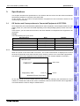
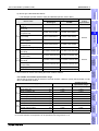
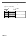
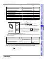
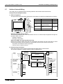
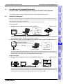
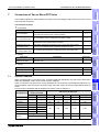
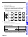
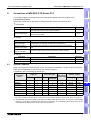
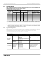
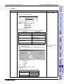
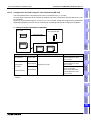
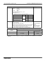
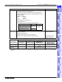
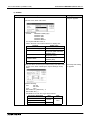
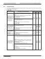
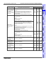
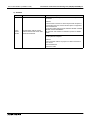
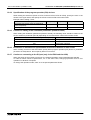
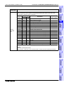
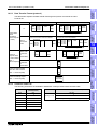
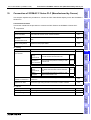
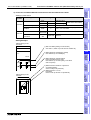
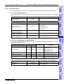
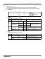
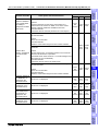
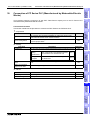
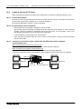
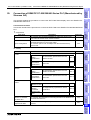
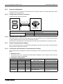
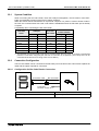
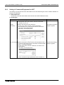
Communication Setting Specifications
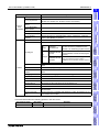
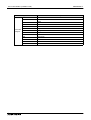
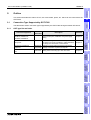
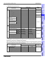
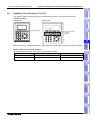
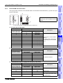
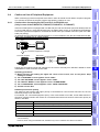
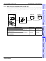
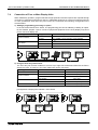
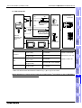
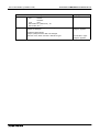
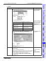
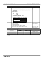
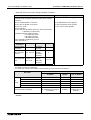
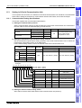
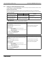
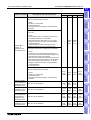
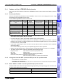
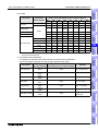
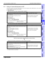
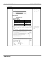
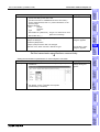
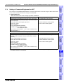
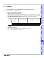
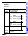
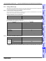
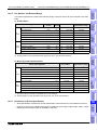
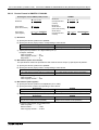
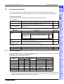
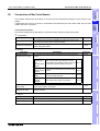
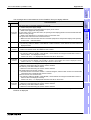
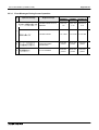
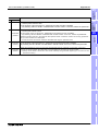
The table below shows the transmission specifications available in the GOT-F900.
Set the transmission specifications in accordance with those in the microcomputer.
Setting in microcomputer
Connection of
FX Series
Positioning
8 or 7 bits
None, even or odd
1 or 2 bits
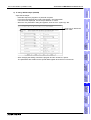
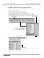
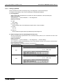
- For the GOT-F900 transmission specifications setting method, refer to section 14.7.
14.4
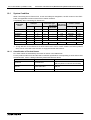
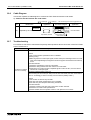
Memory Map
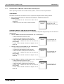
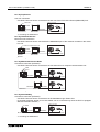
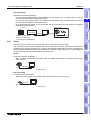
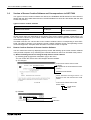
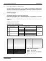
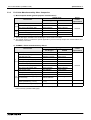
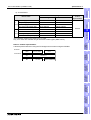
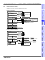
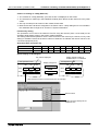
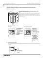
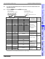
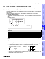
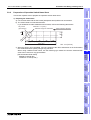
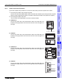
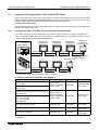
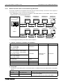
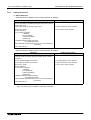
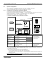
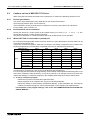
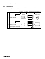
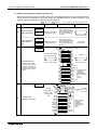
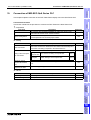
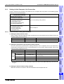
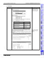
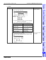
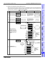
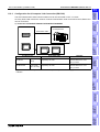
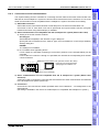
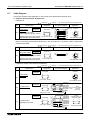
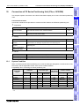
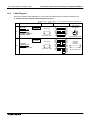
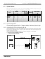
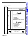
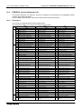
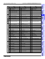
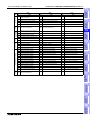
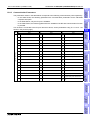
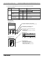
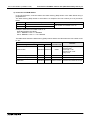
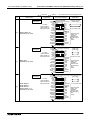
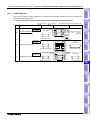
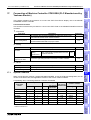
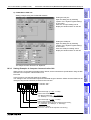
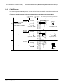
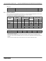
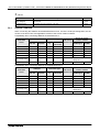
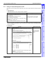
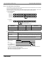
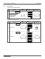
The data stored in the GOT-F900 is classified into word data (D) and bit data (M).
An address is assigned to each data, and each data is positioned as described below.
14
Data Area
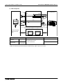
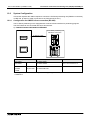
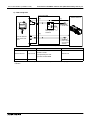
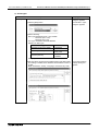
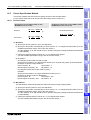
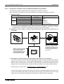
The m icrocom puter specifies data by "address". The screen creation softw are specifies data by "D " or "M ".
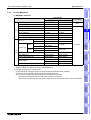
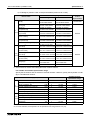
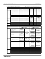
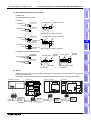
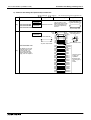
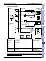
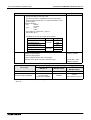
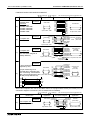
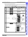
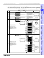
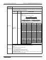
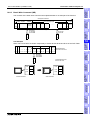
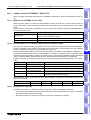
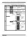
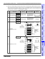
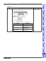
1) Word data (D)
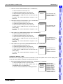
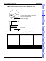
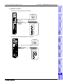
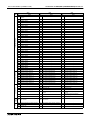
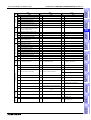
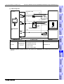
There are 4096 word devices (D0 to D4095). A serial number (address) is assigned to each of them.
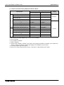
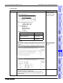
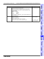
a) Word data (16 bits)
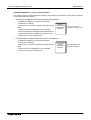
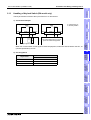
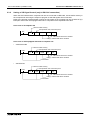
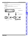
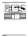
Each 8-bit word data is lined in the order of upper side (H) and lower side (L).
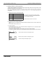
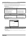
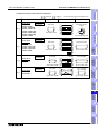
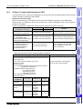
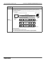
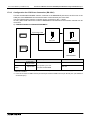
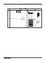
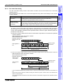
b) Double word data (32 bits)
Each 16-bit word data is lined from the higher address to the lower address.
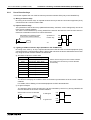
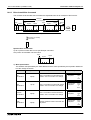
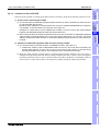
When a 32-bit numeric value is displayed on the GOT-F900, if two word devices are located in the
reverse order, the correct value is not displayed because the most significant bit is regarded as
the sign (+ or -).
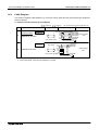
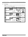
Specification by
microcomputer
Memory inside GOT-F900
(device name specified by screen creation software)*1
Address
Word data (16 bits)
1FFFH
D4095(L)
1FFEH
D4095(H)
1FFDH
D4094(L)
1FFCH
D4094(H)
:
:
0003H
D1(L)
0002H
D1(H)
0001H
D0(L)
0000H
D0(H)
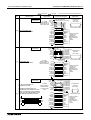
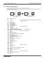
Double word data (32 bits)
15
16
17
D4095
(D4095, D4094)
D4094
:
18
D1
(D1, D0)
D0
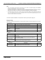
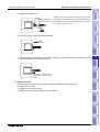
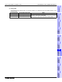
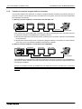
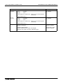
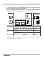
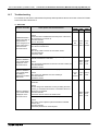
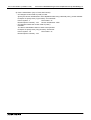
*1 "D****" shown in this chapter indicates a virtual device inside the GOT-F900, but does not indicate any
data register of the PLC.
19
Connection of
SLC500
Series PLC
14.4.1
13
Connection of
FREQROL
Inverter
Setting invalid
Connection of
Microcomputer
Flow control DSR/DTR or XON/XOFF
Connection of
SYSMAC C
Series PLC
Parity bit
Data
format Stop bit
Connection of
FLEX-PC N
Series PLC
Data bit
12
Connection of
Machine Controller
Setting range
19200 or 9600 or 4800 or 2400 or 1200 or 600 or 300 bps
Connection of
FP Series PLC
Item
Baud rate
20
14-7
Connection of
SIMATIC S7
Series PLC
14.3.2
Connection of
MELSEC-Q
Series PLC
11