1
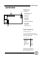
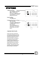
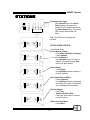
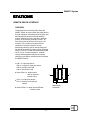
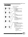
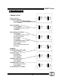
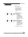
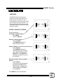
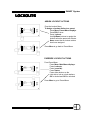
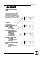
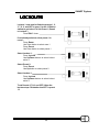
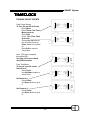
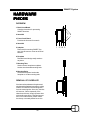
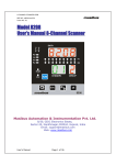
SMART System
OVERVIEW
CONNECTORS
1
2
1. Combines:
PIN 1-8: Combine Inputs
PIN 10: Ground
2. DMX Output:
PIN 1: Ground
PIN 2: DataPIN 3: Data+
3. Power/Serial Connection:
PIN 1: Ground
PIN 2: Serial +
PIN 3: Serial PIN 4: +9 to 24 VDC
3
POWER CONSUMPTION
Operating Voltage: 9-24V
For small (1-8 Stations) systems 15VDC is
sufficient. Larger systems (9-16 Stations) must
use a 24VDC Power Supply.
Current (12VDC)
Master Station
LCD Slave
Station
110mA
50mA
2/10/IR Stations
60mA
100mA*
100mA
Slider Stations
RDI
* Rating based upon 10 channel
slider. Lesser channel models will
have a smaller maximum value.
3