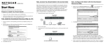
1
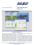
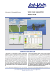
Alternative & Renewable Energy WIND FARM SIMULATOR MODEL 46128 GENERAL DESCRIPTION A Wind Farm is a set of Wind Turbines, located near each other, sharing a common point of connection to the electrical distribution grid called a Common Connection Point. Generally, a Wind Farm has a SCADA (Supervisory Control and Data Acquisition) system used to control individual wind turbines and monitor the entire wind farm. For example, the wind farm operator may use the SCADA control system to implement operational policies of the owner. This SCADA system is also used to monitor the operational aspects of the Wind Farm and give technicians a view of how the systems are behaving. Center is an installation where the set of wind turbines can be controlled, monitored, and maintained. The Wind Farm Simulator simulates the behavior of every aspect of the wind turbines in a wind farm. A simulated SCADA system and a user friendly HMI (Human Machine Interface) create an ideal Operator and Technician Training System. The wind turbines in this software program are modeled after the popular Bonus 1300 KW wind turELQHDYDULDEOHSLWFKVWDOOUHJXODWHGGXDO¿[HGVSHHG wind turbine with a squirrel cage asynchronous generator. Additional versions of the Wind Farm Simulator are planned for doubly-fed induction generators. From an operational standpoint, a Wind Farm Control The Wind Farm Simulator is a software-only solution: no (732) 938-2000 / 800-LAB-VOLT, FAX: (732) 774-8573, E-MAIL: [email protected] (418) 849-1000 / 800-LAB-VOLT, FAX: (418) 849-1666, E-MAIL: [email protected] INTERNET: http://www.labvolt.com WIND FARM SIMULATOR MODEL 46128 GENERAL DESCRIPTION (cont.) special hardware is required, only a PC with adequate performance capabilities. The HMI is designed to be user-friendly and intuitive. It presents every parameter as well as the values of the signals, both internal to the wind turbine and published to the SCADA system. Each wind turbine in the wind farm has its own dedicated simulator, enabling users to change individual parameters independently of the other turbines and observe the resulting behavior of each wind turbine. Access to each signal and parameter is designed to easily change the different scenarios that the user may want to create and observe. Controlling and monitoring of the wind turbines is done through communication lines that tie each wind turbine to a central SCADA system where the operator of the Wind Farm can monitor the status and production of each system, shut each system down, give permission for startup, etc. The SCADA system also collects data from the wind turbines and stores it for further analysis. All these functionalities are also exercised in the Wind Farm Simulator. The Wind Farm Simulator solves the problem of how to train personnel who must understand the behavior of the sub-systems of the wind turbine as well as the wind farm as a whole. Wind farm operators need their technicians to understand hundreds of operating parameters and to be able to react to a plethora of nominal and faulty operating conditions. A technician or operator is able to reproduce with the Wind Farm Simulator situations such as: vibration sensor activated, motor superheated, asymmetry of currents, upper voltage exceeded, lower voltage exceed, (Security) UPS failure, hydraulic brake pump subsystem starting too often or pumping for too long, excessive brake time, gear bearing superheated, thyristors superheated, bypass contactor welded, bypass contactor not working, excessive angle error in the pitch angle of any of the three blades, pitch oil error, yaw position error, error in the RPM reader, brake lining too thin, gear oil pressure too low, untwisting cables error, etc. Nothing but a wind power generation system simulator, operating under an unlimited number of conditions, can impart the type of advanced training required. A simulator is able to create the meteorological as well as electrical, and mechanical operational scenarios that could not be produced on-demand with a real wind turbine. In spite of having access to real systems to train their technical personnel for installing, commissioning and servicing their wind turbines, a simulator is seen as a necessary tool for advanced learning by the wind energy industry. The Wind Farm Simulator addresses these requirements using two elements within the software: a) elaborated software models of the behavior of each subsystem in the wind turbine; b) graphic user interfaces that facilitate the setting and visualizing of conditions for these subsystems. TABLE OF CONTENTS General Description ................................................................................................................... 1 Topic Coverage.......................................................................................................................... 2 Equipment List ........................................................................................................................... 3 Software Description ................................................................................................................. 3 TOPIC COVERAGE What is a Wind Farm? Wind Farm Operations What is a Wind Turbine? Teaching Sessions Structure of the Wind Farm Simulator Technical Data used in the WFS WT and WFS SCADA Physics of a Wind Turbine 2 EQUIPMENT LIST FOR WIND FARM SIMULATOR, MODEL 46128 QTY DESCRIPTION ORDERING NUMBER 1 Manual Package: Incl. (1) Binder, (3) Posters, and (1) User Manual ............................................ 88126 1 Wind Farm Simulator Software CD ............................................................................................... 87422 1 Wind Farm Simulator Resource CD .............................................................................................. 87905 SOFTWARE DESCRIPTION Wind Turbine Block Diagram Structure of Simulator The connection of the generator to the grid while in production is direct. For the “cut-in” operation, the WT uses a set of thyristors for the connection of the generator to the grid during a short, controlled, period of time. The ¿JXUHDERYHVKRZVWKHLQWHUQDOVWUXFWXUHRIDW\SLFDO:7 The WFS includes two applications that simulate the behavior of: an entire wind farm, organized around its SCADA system. a single wind turbine installed in a wind farm The WFS’s main purpose is to serve as a training system for operators of wind farms and service personnel of industrial wind turbines. The WFS applications follow the principles described below: Simulators behave as close to their real counterparts as possible. The Human Machine Interface provides interaction with as many components and subsystems of wind turbines as possible. This complete HMI allows the user to access not only the variables normally available through the Wind Turbine Control Terminal, but 3 WIND FARM SIMULATOR MODEL 46128 also simulated “cables” corresponding to connections among the subsystems. The graphic representations help users identify the wind turbine components. Timing of the evolution of the internal signals are as close to real counterpart as possible: for example if the blades reported rotational speed is 12 rpms, its 3D representation rotates at that speed. When convenient, real parameters have been adapted to classroom settings for the sake usability. For example. the angular speed of the yawing in a real turbine is approximately 1º per second, the simulator uses 5º so the changes can happen faster, optimizing the trainee’s time. These two applications are based on LdP (Lenguaje de Procesos© ACM), a framework specialized for developing and executing simulations. Both can be executed simultaneously. SCADA Synoptics Control The User Interface for the WFS SCADA includes the following items: Iconic view of each WT, indicating its internal name, its status (Production, Stopped or Out of Order), the actual production (in percent with respect to the maximum), and the cables that connect it to the Point of Common Connection (typically the Substation). A SCADA view, or a spreadsheet view, where the user can access additional information on each WT and PDNHPRGL¿FDWLRQVWRVRPHRIWKHP A Maintenance framework through which the user can simulate the change of the WT selected in the SCADA view, from “Out of Order” to “Operational.” A Production framework, also common in most wind farm SCADAs, where the user can see the actual Total Power production, together with the Maximum available Power from the wind. The Synoptics contain the HMI of the simulator asso A Meteorological framework where the user can set FLDWHG ZLWK WKH FRQ¿JXUDWLRQ ¿OH $ V\QRSWLF HOHPHQW values for real situations that are obtained from the allows the user to visualize, in real time, the value of meteorological station of the Wind Farm. VSHFL¿HGVLJQDOVDQGWRPRGLI\WKRVHYDOXHV6KRZQLV An “Automatic Dispatching” checkbox through which the basic control synoptic of the WT Emulator. Default the user can establish a “manual” of “Automatic Disview is shown at left; expanded drop-down menu shown patching” operation of the Wind Farm. at right. 4 SYNOPTICS USED IN PROGRAM Drive Train It has two main “Views”, selectable through the menu bar: Internal View displays the internal elements in the Nacelle and the Farm View that shows the WT in the Wind Farm. Wind and Nacelle The purpose of the Wind & Nacelle synoptic is: This WTDriveTrain synoptic has been designed to display the most important signals that arrive in the Nacelle emulator, and the signals going out from the Nacelle emulator. The following is a list of these signals: Rotor speed (rpms), from the Nacelle emulator. Generator speed (rpms), from the Nacelle emulator. Pitch value (º), from the Controller emulator. Hydraulic circuit pressure of the braking system, from Nacelle emulator. Hydraulic circuit Pump status, from the Controller emulator. The state of the valve in the hydraulic circuit, controlled by the “Soft brake” and “Hard brake” coming from the Controller emulator. The status of the Pressure switch in the hydraulic circuit. The Brake Released status (ON or OFF) from the Nacelle emulator. The state of each Generator connection switch (Large: 4 poles and Small : 6 poles), from the Controller emulator. The state of the Over speed detectors (VCU, HCU) The state of the Tower vibrations sensor. The temperatures for the Ambient (setting), Rotor bearing, the Gearbox and the Generator from the Nacelle emulator. To allow the user to control wind speed and direction. To show the Nacelle orientation. To show the number of cable turns connecting the Nacelle’s generator to the Electric Panel at the bottom of the WT. To show the (simulated) wind vane signal. To show the signals controlling the yawing motors, the wind vane signal and the power cable turns. There are also control boxes that allow the user to change wind speed and direction, and manually control the yawing motors. 5 WIND FARM SIMULATOR MODEL 46128 Electrical Panel The multiview Electrical Panel synoptic combines representations for many aspects of the electrical power circuits of a WT. Each WT is connected to the PCC (Point of Common Connection) on the Wind Farm either in low voltage (typically 690V grid) or at medium voltage (15KV or higher). In the later situation, the WT includes a low-to-medium voltage transformer, generally located in the base of the tower. 6 Control Terminal The various parts of this synoptic display as much information as possible to the user about the parameters values and a number of internal variables. It is used to display the following information: Outputs Inputs From the Grid Parameters Values for internal variables used in the algorithms. Buttons for the Manual Yawing control Buttons for activating the “normal” operation (“START”) or passing to Manual control (“STOP”) Information about the internal State Machines (Operation and Security) Parameters Wind Farm Simulator Package This synoptic is used to see and modify the Parameters values used in the application. Parameters behave as RXWSXW VLJQDOV RU ¿[HG YDOXH JHQHUDWRUV HLWKHU DQDORJ or digital. Signals and Connections Editor This synoptic displays a list of input signals. The color distinguishes analog or digital signals. 7 WIND FARM SIMULATOR MODEL 46128 5HÀHFWLQJ/DE9ROW¶VFRPPLWPHQWWRKLJKTXDOLW\VWDQGDUGVLQSURGXFWGHVLJQGHYHORSPHQWSURGXFWLRQLQVWDOODWLRQDQGVHUYLFHRXUPDQXIDFWXULQJDQGGLVWULEXWLRQIDFLOLW\KDVUHFHLYHGWKH,62FHUWL¿FDWLRQ Lab-Volt reserves the right to make product improvements at any time and without notice and is not responsible for typographical errors. LabVolt recognizes all product names used herein as trademarks or registered trademarks of their respective holders. © Lab-Volt 2011. All rights reserved. 8 86906-00 Rev. A2