1
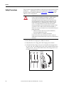
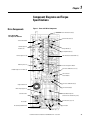
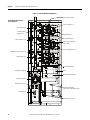
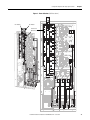
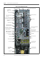
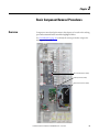
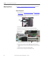
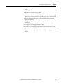
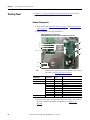
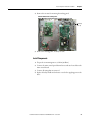
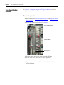
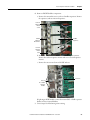
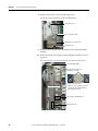
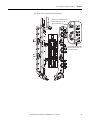
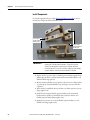
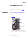
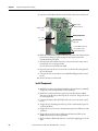
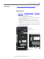
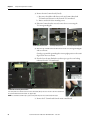
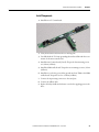
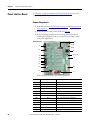
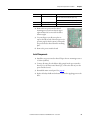
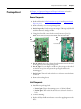
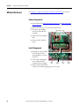
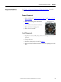
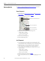
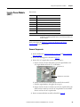
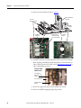
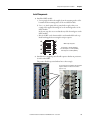
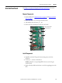
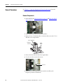
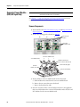
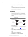
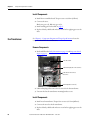
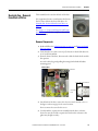
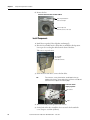
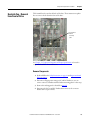
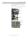
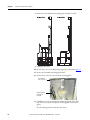
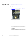
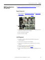
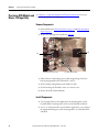
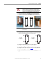
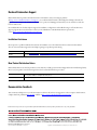
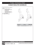
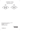
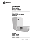
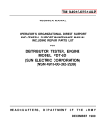
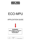
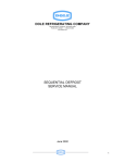
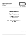
Chapter 3
Component Replacement Procedures
5. Remove the Gate Interface board. See page 53.
Current Transducer
Assembly
Tie Down
Capacitor Mount
Output
Busbar
Snubber
Capacitors
IGBT
Gate Interface
Board Assembly
(not shown above)
AC Output
Busbar
6. Carefully examine the transitional busbar and bus capacitors for damage.
When replacing any IGBT, Rockwell Automation recommends that you
replace all bus capacitors. If needed, refer to Bus Capacitor on page 45 to
replace damaged bus capacitors.
Example of IGBT
Module Failure
Bus Capacitor,
under Transitional
Busbar
Transitional Busbar
Flexible Capacitor
Busbars
7. Remove the eight screws that secure the IGBT to the chassis.
8. Remove the IGBT by tipping the right edge out first.
50
Rockwell Automation Publication 20B-IN024C-EN-P - June 2012