1
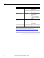
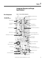
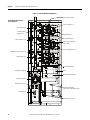
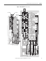
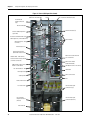
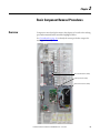
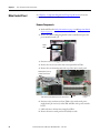
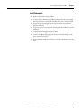
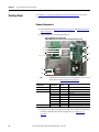
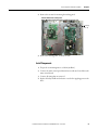
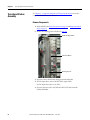
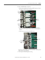
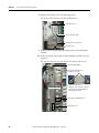
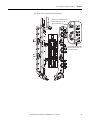
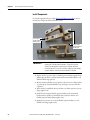
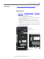
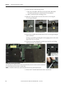
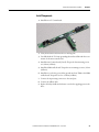
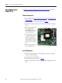
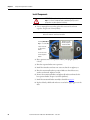
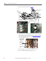
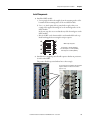
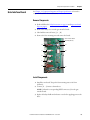
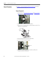
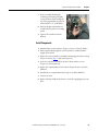
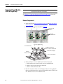
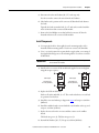
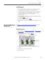
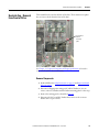
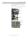
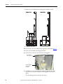
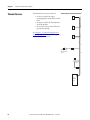
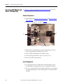
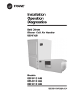
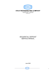
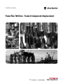
Chapter 2
Basic Component Removal Procedures
Transitional Busbar
Assembly
See Chapter 1 - Component Diagrams and Torque Specifications to locate the
component detailed in these instructions.
Remove Components
1. Read and follow the Safety Precautions on page 12 and Important Initial
Steps on page 13.
2. Remove the stacking panel as detailed on page 26.
DC Choke Output Cables
Transitional Busbar
Balancing Resistor
3. If present, remove all customer wiring to transitional busbar.
4. For AC input drives, remove the DC choke output cables.
For DC input drives, there is no choke.
5. If present, disconnect the +DC IN and +DC OUT cables from the
transitional busbar.
28
Rockwell Automation Publication 20B-IN024C-EN-P - June 2012