1
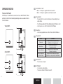
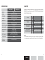
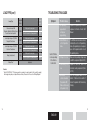
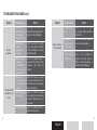
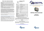
Installation Manual
Switch
Switch
USER MANUAL
ENGLISH
用戶手冊
簡體中文
用戶手冊
繁體中文
This Installation Manual applies to the following products:
Product No.
Description
U201SRY2KW
U202SRY2KW
1-Gang 2000VA Switch
2-Gang 2 x 1000VA Switch
1
ENGLISH
IMPORTANT NOTES
HOW TO USE THIS MANUAL
This manual explains how to install and operate your ULTI 1-Gang and 2-Gang Switches.
PRODUCT SAFETY
The ULTI unit complies with IEC60669-2-1. The Remote Control Unit operates at a RF
frequency band of 315MHz or 434MHz. Please contact local sales representatives for
specifications in various countries. The effective radiated power of the Remote Control
Units does not exceed 10mW.
WARRANTY
ULTI products come with a one-year, equipment-only warranty. For more details, please
visit www.clipsal-ulti.com
To enjoy product warranty, simply:
register on line by visiting the Warranty Registration section on www.clipsal-ulti.com
Customer Service Email: [email protected]
URL: www.clipsal-ulti.com
CONTENTS
IMPORTANT NOTES
2
CONTENTS
3
ULTI PACKAGE COMPONENTS
4
INTRODUCTION
5
OPERATING FUNCTION
6
INSTALLATION PROCEDURES
8
COVER PLATE REMOVAL
9
WIRING DIAGRAM
10
SPECIFICATIONS
12
LOAD TYPE
13
TROUBLE SHOOTING GUIDE
15
2
3
ENGLISH
ULTI PACKAGE COMPONENTS
INTRODUCTION
ULTI CONCEPT
Control Unit
ULTI, The Ultimate Switch, is a Clipsal Concept. It is a state-of-the-art lighting control and
electrical automation scheme for residential, hotel and office use, offering sophisticated
design, operational simplicity and flexibility to control electrical devices.
(Cover Plates are to be purchased separetely)
ULTI WIRELESS LIGHTING CONTROL SOLUTION
or
1-Gang Switch Module
2-Gang Switch Module
With ULTI, you can use a Remote Control Unit to control all functions, including preprogramming of multi-combination light groups and electronic home appliances for up to
five different scenarios. With a simple touch of a button, you can call upon the preferred
lighting for your chosen activity.
This product operates as a standard wall-mounted Switch / Dimmer and can be retrofitted
into British standard wall box.
ULTI TERMINOLOGY:
Installation Manual
Screws x 4
Optional Items :
Zone
Switch
Dimmer
Scene
-
An area illuminated / controlled by a single lighting circuit.
A switch that controls the on / off of a zone.
A switch that controls the on / off and dimming level of a zone.
A “Scene” is defined as a combination of lights and electronic appliances across
various zones with different light levels. You can set your favourite scenes by following
Programming Procedures in the Remote Control Unit manual.
Universal Deco Spacer Set
Product No. : UAX-001
4
3.5mm
10mm
5
ENGLISH
OPERATING FUNCTION
1-2
Functions of ULTI Switch
ULTI allows you to create different scenes and select scenes with ULTI Switch / Dimmer
and Remote Control Unit, which detailed programming procedures are available in Remote
Control Unit manual.
1-Gang Switch
3
• Control Buttons 1 and 2:
Button 1 : Short press to toggle the first channel on and off.
Button 2 : Short press to toggle the second channel on and off.
3
• Program Button
- Press and hold for 5 seconds to switch between the two backlight colours
amber and blue.
- Press 6 times repeatedly within 1 minute will disable/enable the RF wireless control.
- Used to pre-set scenes. Refer to Remote Control Unit Manual.
4
• Clear Button
- Used to clear programmed scenes. Refer to Remote Control Unit Manual.
5
• Program LED
4
Status
7
1
Turns on red
Flashes 3 times
5
2-Gang Switch
3
6
Flashes continuously
Flashes continuously in
pattern of 2 flashes
4
6
• Release Button
- Press to release cover plate.
7
• LED Backlight
- 2 colour options, amber and blue.
- Turns on when the Switch / Dimmer is turned off.
1
7
2
5
Connotation
Program Button has been pressed meaning
Switch/Dimmer is in Programming mode
Clear Button has been pressed
& command is carried out.
Memory is full. Refer to Memory Clearing
Procedure to clear memory.
RF wireless control is disabled; hence Remote
Control Unit can no longer control this Switch/Dimmer.
6
6
7
ENGLISH
INSTALLATION PROCEDURES
1. Important:
• Always turn OFF the Miniature Circuit
Breaker (MCB) before installation,
maintenance or servicing of electrical
appliance.
• Excessive load will damage the
product (Please refer to Load table
for permissible maximum loading).
2. Make sure the cover plate is separated
from the Switch / Dimmer module before
installation takes place.
3. Make sure there is sufficient depth
(40mm) on the wall to install ULTI
Switch / Dimmer. A standard BS wall box
must be used for installation.
COVER PLATE REMOVAL
5. Fasten the screws of both terminals and
make sure wires are properly secured.
6. Switch on the power source from
the MCB to test the Switch / Dimmer is
functioning. LED backlight should turn
ON when the Switch / Dimmer is off.
7. Directly place ULTI Switch / Dimmer into
the wall box and mount it on the wall by
fastening the two screws and then put
the screw caps on.
1. Push the release button upward to
disengage the clip. Release button is
located on the bottom of the Switch /
Dimmer module. The cover plate will
spring outwards.
2. Hold the cover plate and push upwards
and away from the Switch / Dimmer
module.
8. Set your favourite scene by following
the programming procedures in Remote
Control Unit manual.
9. Clip the cover plate back in place.
4. Connect the load cables to the Load
terminal first and then the power cables
to the Live terminal after.
Optional
Note: In case of insufficient depth,
attach the Deco Spacer at the back
of the module before continuing the
procedures follow.
push upward
8
9
ENGLISH
WIRING DIAGRAM
Wiring diagram for connecting energy saving lamp or compact fluorescent lamp with
ULTI.
1-Gang 2000VA Switch
Capacitor (0.47uF 275VAC X2)
Load
Fluorescent Lamp, Compact Fluorescent Lamp or Energy Saving Lamp
Live
2-Gang 2 x 1000VA Switch
Load 1
Load 2
Live
10
11
ENGLISH
LOAD TYPE
SPECIFICATIONS
1-Gang Switch
Operation
Memory
LED Backlight
2-Gang Switch
Toggle on/off
Up to 8 Remote Control Units
The table below shows the maximum rating for 1-gang and 2-gang switch operating at
220-240V AC. However, they can also operate at 110-130V AC, its maximum rating would
be half of the rating shown below.
Changeable Amber / Blue colour
Please Refer to Load Table
Lamp Type
1-Gang Switch
Total Load
Minimum Load
25W
Maximum Load
Please Refer to Load Table
Incandescent
Lamp
2000W
Load Type
Operating Temperature
Operating Humidity
Operating Voltage &
Frequency
0 °C to + 40 °C
0% to 95%
110-130V AC, 60Hz
220-240V AC, 50/60Hz
Radio Frequency
Available in 315MHz & 434MHz
(Please consult your regional office)
Mounting Centres
60.3mm
Dimensions
(H) x (W) x (D)
Fluorescent Lamp With
Electronic Ballast*
Fluorescent Lamp With
Magnetic Ballast AND Power
Factor Correction Capacitor*
1800W
2-Gang Switch
Total Load
Max power for one gang
2000W
Max total power for all gangs added
2000W
Max power for one gang
1800W
Max total power for all gangs added
1800W
Max power for one gang
1800W
Max total power for all gangs added
1800W
1800W
Remarks:
* Each 0.47uF/275VAC, “X2” bypass capacitor is required to connect parallel to the load in the gang(s)
with energy saving lamp or compact fluorescent lamp. Please refer to the section of Wiring Diagram.
87mm x 87mm x 39mm
12
13
ENGLISH
LOAD TYPE (con’t)
Lamp Type
TROUBLE SHOOTING GUIDE
1-Gang Switch
Total Load
Fluorescent Lamp With
Magnetic Ballast but Without Power
Factor Correction Capacitor*
1000W
Low Voltage Halogen (12V) With
Magnetic Transformer
1900W
Low Voltage Halogen (12V) With
Electronic Transformer
1900W
Energy Saving Lamp*
Exhaust Fan*
1400W
2-Gang Switch
Total Load
Max power for one gang
1000W
Max total power for all gangs added
1000W
Max power for one gang
1900W
Max total power for all gangs added
1900W
Max power for one gang
1900W
Max total power for all gangs added
1900W
Max power for one gang
1400W
Max total power for all gangs added
1400W
Applicable
Symptom
Switch / Dimmer
is not responding
to the Remote
Control Unit.
Remarks:
* Each 0.47uF/275VAC, “X2” bypass capacitor is required to connect parallel to the load in the gang(s)
with energy saving lamp or compact fluorescent lamp. Please refer to the section of Wiring Diagram.
14
Possible Cause
Solution
1.Not previously
programmed
or improper
programming.
Repeat the Programming Procedures
explained in Remote Control Unit
Manual.
2.Switch/Dimmer is
set to Programme
mode.
The LED indicator is turned on red now,
indicating the unit is in Programming
mode. If programming is not required,
press the Programme Button to exit
Programming mode.
3.Voltage is too low.
Make sure the operating voltage range
is within the requirement (Refer to P.12).
4.Power rating is too
low.
Replace a load that meets the
minimum loading requirement (Refer
to P.12).
5. RF wireless
control is disabled.
(Programme LED
flashes continuously
in the pattern of 2)
Press the Programme Button of the
Switch / Dimmer 6 times within 1
minute. Programme LED should stop
flashing.
15
ENGLISH
TROUBLE SHOOTING GUIDE (con’t)
Symptom
Unable to
programme
Main light or LED
backlight does not
turn on.
Possible Cause
Solution
1.Red Programme
LED flashes after
the Programme
Button is pressed.
This indicates the memory is full.
(Refer to Memory Clearing Procedures
in Remote Control Unit Manual).
2.The Switch does
not receive
programming
commands.
Check the position of the function
selector at the back of the Remote
Control Unit. Make sure it is in the
Programme position.
3.RF wireless control
is disabled.
(Programme LED
flashes continuously
in the pattern of 2)
Press the Programme Button of
the Switch 6 times within 1 minute.
Programme LED should stop
flashing.
1.Wires are not
properly secured
or connected in the
terminals.
Make sure the wires are secured,
screws are fastened and the Live or
Load wires have been connected to
the correct terminals.
2.MCB is OFF or has
been tripped.
Switch on the MCB. If a breaker
continually trips, contact a registered
electrician to find out the cause of
the problem.
3.Temporary disorder.
Switch off the MCB and then on
again to reset the switch.
Symptom
Main load is turned
off automatically
16
Possible Cause
Solution
1.Power rating is too
low.
Replace the load that meets
the minimum loading requirement
(Refer to P.12).
2.Wires are not
properly secured
in the terminals.
Make sure the wires are secured and
screws are fastened properly.
3.Controlled by other
remote control unit
within the area
Determine which remote control
unit(s) is (are) controlling the
particular main light. (Refer to
Memory Clearing Procedures in
Remote Control Unit Manual).
17
ENGLISH