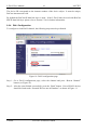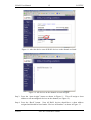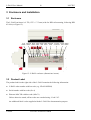
1
L-DALI BACnet/DALI Gateway User Manual LOYTEC electronics GmbH L-DALI User Manual 2 This page is intentionally left blank! Version 1.0 LOYTEC electronics GmbH LOYTEC L-DALI User Manual 3 LOYTEC Contact LOYTEC Stolzenthalergasse 24/3 A-1080 Vienna AUSTRIA/EUROPE [email protected] http://www.loytec.com Version 1.0 Document No. 88071901 LOYTEC MAKES AND YOU RECEIVE NO WARRANTIES OR CONDITIONS, EXPRESS, IMPLIED, STATUTORY OR IN ANY COMMUNICATION WITH YOU, AND LOYTEC SPECIFICALLY DISCLAIMS ANY IMPLIED WARRANTY OF MERCHANTABILITY OR FITNESS FOR A PARTICULAR PURPOSE. No part of this publication may be reproduced, stored in a retrieval system, or transmitted, in any form or by any means, electronic, mechanical, photocopying, recording, or otherwise, without the prior written permission of LOYTEC. L-Chip, LC7093 and L-CORE are trademarks of LOYTEC. Version 1.0 LOYTEC electronics GmbH L-DALI User Manual 4 LOYTEC Contents 1 Introduction..............................................................................................................................8 1.1 Overview............................................................................................................................8 1.2 Scope..................................................................................................................................8 2 Quick-Start Guide.................................................................................................................... 9 2.1 Installation of the L-DALI.................................................................................................9 2.2 Configuration of the L-DALI.......................................................................................... 10 2.2.1 IP Configuration via Console....................................................................................10 2.2.2 IP Configuration via Web Interface.......................................................................... 11 2.2.3 BACnet Configuration.............................................................................................. 13 2.2.4 DALI Configuration.................................................................................................. 14 2.3 Using the L-DALI............................................................................................................17 3 Enclosure and Installation......................................................................................................18 3.1 Enclosure......................................................................................................................... 18 3.2 Product Label...................................................................................................................18 3.3 Mounting..........................................................................................................................19 3.4 LED Signals.....................................................................................................................19 3.4.1 Power LED................................................................................................................ 19 3.4.2 Status LED................................................................................................................ 19 3.4.3 Ethernet Link LED.................................................................................................... 19 3.4.4 Ethernet Activity LED.............................................................................................. 19 3.4.5 Ethernet Config LED.................................................................................................19 3.4.6 Ethernet CN/IP LED................................................................................................. 19 3.4.7 MSTP Activity LED..................................................................................................19 3.4.8 DALI Activity LEDs................................................................................................. 19 3.5 Buttons.............................................................................................................................20 3.5.1 Status Button............................................................................................................. 20 3.5.2 DALI Mode Button................................................................................................... 20 3.5.3 DALI Channel Button............................................................................................... 20 3.5.4 DALI Program Button...............................................................................................21 3.6 DIP-Switch Settings.........................................................................................................21 3.7 Power Supply...................................................................................................................21 3.8 Terminal Layout.............................................................................................................. 22 3.9 Wiring.............................................................................................................................. 22 Version 1.0 LOYTEC electronics GmbH L-DALI User Manual 5 LOYTEC 4 Console Interface................................................................................................................... 24 4.1 Self Test........................................................................................................................... 24 4.2 L-DALI Configuration Menu (Main Menu)....................................................................25 4.2.1 Option 1 – Show device information........................................................................ 25 4.2.2 Option 2 – Update firmware......................................................................................25 4.2.3 Option 3 – System configuration.............................................................................. 25 4.2.4 Option 4 – DALI maintenance.................................................................................. 26 4.2.5 Option 5 – IP configuration.......................................................................................26 4.2.6 Option 7 – BACnet configuration............................................................................. 26 4.2.7 Option 8 – Reset configuration (factory defaults).....................................................26 4.2.8 Option 9 – Device statistics.......................................................................................26 4.2.9 Option 0 – Reset L-DALI..........................................................................................26 4.3 System Configuration Menu............................................................................................26 4.3.1 Option 7 – FTP server, 8 – FTP server port.............................................................. 26 4.3.2 Option 9 – Web server, 0 – Web server port.............................................................27 4.4 DALI Maintenance Menu................................................................................................27 4.4.1 Option 1 – DALI channel..........................................................................................27 4.4.2 Option 2 – DALI configuration.................................................................................27 4.4.3 Option 3 – DALI statistics........................................................................................ 27 4.4.4 Option 4 – DALI analyzer.........................................................................................29 4.5 DALI Configuration Menu.............................................................................................. 29 4.5.1 Option 1 – List devices, 2 – Scan & list devices.......................................................29 4.5.2 Option 3 – Auto-assign devices................................................................................ 30 4.5.3 Option 4 – Recover devices...................................................................................... 30 4.5.4 Option 5 – Replace missing devices......................................................................... 30 4.5.5 Option 0 – Reset network..........................................................................................31 4.5.6 Option a – Add device...............................................................................................31 4.5.7 Option c – Configure device..................................................................................... 31 4.5.8 Option d – Delete device.......................................................................................... 31 4.5.9 Option w – Wink device............................................................................................31 4.5.10 Option o – Add OSRAM device............................................................................. 31 4.5.11 Option r – Read OSRAM CIN................................................................................ 31 4.6 DALI Device Configuration Menu..................................................................................32 4.6.1 Option 1 – Group membership..................................................................................32 4.6.2 Option 2 – Power on level.........................................................................................32 Version 1.0 LOYTEC electronics GmbH L-DALI User Manual 6 LOYTEC 4.6.3 Option 3 – System failure level.................................................................................32 4.6.4 Option 4 – Minimum level........................................................................................ 33 4.6.5 Option 5 – Maximum level....................................................................................... 33 4.6.6 Option 6 – Fade rate.................................................................................................. 33 4.6.7 Option 7 – Fade time................................................................................................. 33 4.6.8 Option 8 – Test dim (rate), 9 – Test dim (time)........................................................ 33 4.7 IP Configuration Menu.................................................................................................... 33 4.7.1 Option 1 – DHCP...................................................................................................... 34 4.7.2 Option 2 – IP Address, 3 - IP Netmask, 4 - IP Gateway...........................................34 4.7.3 Option 5 – Hostname, 6 - Domainname....................................................................35 4.7.4 Option 7 – DNS Servers............................................................................................35 4.7.5 Option 9 – MAC Address..........................................................................................35 4.7.6 Option b – Link Speed & Duplex..............................................................................35 4.8 BACnet Configuration Menu.......................................................................................... 35 4.8.1 Option 1 – Device ID................................................................................................ 36 4.8.2 Option 2 – Device name, 3 – Device description, 4 – Device location.................... 36 4.8.3 Option 9 – Data Link Layer...................................................................................... 36 4.8.4 Option 0 – Configure Data Link Layer..................................................................... 36 4.9 Reset Configuration Menu...............................................................................................38 4.9.1 Option 1 – Reset everything to factory defaults........................................................38 4.9.2 Option 2 – Reset all passwords................................................................................. 38 4.10 Device Statistics Menu.................................................................................................. 38 4.10.1 Option 4 – IP statistics............................................................................................ 38 4.10.2 Option 7 – BACnet statistics...................................................................................40 5 Web Interface.........................................................................................................................41 5.1 Start Screen and Account Management...........................................................................41 5.2 Device Information..........................................................................................................43 5.3 Device Configuration.......................................................................................................43 5.3.1 System Configuration................................................................................................43 5.3.2 DALI Configuration.................................................................................................. 44 5.3.3 IP Configuration........................................................................................................47 5.3.4 BACnet Configuration.............................................................................................. 49 5.4 Device Statistics...............................................................................................................50 5.4.1 IP Statistics................................................................................................................50 5.4.2 DALI Statistics..........................................................................................................51 Version 1.0 LOYTEC electronics GmbH L-DALI User Manual 7 LOYTEC 5.5 Reset, Contact, Logout.................................................................................................... 52 6 BACnet Interface................................................................................................................... 53 6.1 Data Link Layers............................................................................................................. 53 6.2 BACnet objects................................................................................................................53 6.2.1 Device Object............................................................................................................ 53 6.2.2 Analog Output Object............................................................................................... 57 6.2.3 Multi-State Output Object.........................................................................................62 7 DALI Interface.......................................................................................................................66 7.1 Compatibility................................................................................................................... 66 7.1.1 Supported Ballasts.....................................................................................................66 7.1.2 Multi-Master Operation.............................................................................................66 7.1.3 Vendor Specific Extensions...................................................................................... 66 7.2 Installation Scenarios.......................................................................................................66 7.2.1 Installation in a Single-Master Environment............................................................ 66 7.2.2 Installation in a Multi-Master Environment..............................................................67 7.2.3 Replacement of a Single Broken DALI device......................................................... 67 7.2.4 Replacement of Multiple Broken DALI devices.......................................................68 7.2.5 Replacement of Broken L-DALI...............................................................................68 8 Updating the L-DALI Firmware............................................................................................ 69 8.1 Firmware Update via FTP............................................................................................... 69 8.2 Firmware Update via the Console................................................................................... 70 9 Troubleshooting..................................................................................................................... 72 9.1 Technical Support............................................................................................................72 10 Application Notes................................................................................................................ 73 11 L-DALI Firmware Versions.................................................................................................74 12 Specifications....................................................................................................................... 75 13 Revision History.................................................................................................................. 76 Version 1.0 LOYTEC electronics GmbH L-DALI User Manual 8 LOYTEC 1 Introduction 1.1 Overview The L-DALI gateway enables Light Control through a BACnet interface. DALI (Digital Addressable Lighting Interface) is part of the IEC 60929 standard. It is used to dim and switch luminaires from most of the leading European manufacturers. DALI also supports devices like multi-sensors (e.g. for brightness, movement, temperature, etc.) and intelligent switches. L-DALI provides 4 independent DALI channels and can control up to 64 DALIbased luminaires per DALI channel individually. All luminaires are monitored for defective lamps. L-DALI can provide this information to the Building Management System (BMS) through its BACnet interface. On the BACnet side L-DALI supports BACnet/IP and BACnet MS/TP. The complete L-DALI configuration can be performed through the built-in Web server or a console interface. Thus, the commissioning and maintenance of the DALI system can be done using a standard Web browser on a PC. Figure 1: The L-DALI can handle up to four DALI channels. 1.2 Scope This document covers L-DALI devices with firmware version 1.0. See Section 11 for differences between the different L-DALI firmware versions. It is assumed the reader is familiar with the basic concepts of BACnet and DALI. Version LOYTEC electronics GmbH L-DALI User Manual 9 LOYTEC 2 Quick-Start Guide 2.1 Installation of the L-DALI It is recommended to use the LDALI-PWR4-230 power supply together with the L-DALI. Connect the L-DALI to the LDALI-PWR4-230 and to the DALI network as shown in Figure 2. To allow for easy configuration it is recommended to always connect the L-DALI to the Ethernet network. Figure 2: Wiring the L-DALI. After the DALI ballasts have been installed and connected to the DALI network, the installation can be tested by following these steps: 1. Check that the DALI LEDs (“DALI x ACT”, where x is 1 to 4) do not light up red. If one of these LEDs are red, check the proper connection of the bus power supply for the corresponding channel. 2. Press the DALI mode button (“ON/OFF/AUTO”) on the front panel of the L-DALI once. Now all DALI ballasts should be switched on (maximum level) and the DALI LEDs on the L-DALI should light up green. Version LOYTEC electronics GmbH L-DALI User Manual 10 LOYTEC 3. Press the DALI mode button again. Now all DALI ballasts should be switched off and the DALI LEDs on the L-DALI should light up orange. 4. Press the DALI mode button again. This should not change the state of the DALI ballasts but return the L-DALI to the auto-mode (control via BACnet interface). If the L-DALI is connected to a BACnet MS/TP network, the MS/TP EIA-485 network must be properly terminated with a termination resistance of 120 ohms connected at each of the two ends of the segment medium. Figure 3 shows how to connect the L-DALI to an MS/TP network. Figure 3: Connect the L-DALI to a BACnet MS/TP network. 2.2 Configuration of the L-DALI The L-DALI can be configured via console interface or via Web interface. To configure the L-DALI the following steps have to be performed: 1. Setup IP configuration (see Sections 2.2.1 and 2.2.2). 2. Setup BACnet configuration (see Section 2.2.3). 3. Setup DALI configuration (see Section 2.2.4). Note: This setup procedure assumes the use of the IP interface. Alternatively, a configuration via the console interface is possible. See Section 4.2 for details. 2.2.1 IP Configuration via Console Use a PC terminal program with communication settings of 38,400 bps / 8 data bits / no parity / 1 stop bit / no handshake. To connect COM1 of the PC to the Console on the L-DALI, use a standard null-modem-cable with full handshaking. Power up the L-DALI or press Return if the L-DALI is already running. The following menu should appear on the terminal: Version LOYTEC electronics GmbH L-DALI User Manual 11 LOYTEC Device Main Menu ================ [1] [2] [3] [4] [5] [7] [8] [9] [0] Show device information Serial firmware upgrade System configuration DALI maintenance IP configuration BACnet configuration Reset configuration (factory defaults) Device statistics Reset device Please choose: Figure 4: Main L-DALI menu. Select 5 from the L-DALI main menu and enter the IP address, netmask, and gateway address. Note that you must use different IP addresses if you are using multiple L-DALIs in your setup. See Section for 4.7 details. IP Configuration Menu ===================== [1] [2] [3] [4] [5] [6] [7] [9] [b] DHCP IP Address IP Netmask IP Gateway Hostname Domainname DNS Servers MAC Address Link Speed & Duplex [q] [x] Quit without saving Exit and save : : : : : : : : : disabled 192.168.1.254 255.255.255.0 192.168.1.1 new <unset> <unset> 00 0A B0 01 02 DB (factory default) Auto Detect Please choose: Figure 5: Enter basic IP settings. Press x to save the IP settings and reset the L-DALI with main menu item 0 in order to let the new IP settings take effect. 2.2.2 IP Configuration via Web Interface Optionally to using the console interface one can also use the Web interface to configure the L-DALI. In a web browser, enter the default IP address 192.168.1.254 of the L-DALI. Note that if your PC has an IP address in a subnet other than 192.168.1.xxx, you must open a command tool and enter the following route command to add a route to the L-DALI: Windows START -> Run command.com Route add 192.168.1.254 %COMPUTERNAME% Version LOYTEC electronics GmbH L-DALI User Manual 12 LOYTEC Figure 6: L-DALI Start Screen. Click on “Config” in the left menu. You will be asked to enter the administrator password in order to change the IP settings. Enter “admin” and select Login. Figure 7: Enter admin as the default administrator password. The Config menu opens. Click on “IP” in the Config menu and enter the IP address, the IP netmask, and IP gateway for this L-DALI as shown in Figure 8. Version LOYTEC electronics GmbH L-DALI User Manual 13 LOYTEC Figure 8: Enter IP address and gateway. Press Save Settings and then reset the device by selecting “reset” in the highlighted text. This changes the IP settings of the L-DALI. 2.2.3 BACnet Configuration To configure the BACnet interface, at least the device ID must be configured (see Figure 9). Figure 9: BACnet device configuration. Version LOYTEC electronics GmbH L-DALI User Manual 14 LOYTEC The device ID corresponds to the instance number of the device object. It must be unique, BACnet internetwork-wide. By default the BACnet/IP data link layer is used. If the L-DALI must be used with BACnet MS/TP data link layer please refer to Section 5.3.4 for further information. 2.2.4 DALI Configuration To configure a fresh DALI channel, the following steps must be performed: Figure 10: DALI configuration page. Step 1: Go to DALI configuration page, select the channel and press “Rescan Channel” button (see Figure 10). Step 2: After the scan finished successfully, press the “Back” button. Now all DALI devices should be listed under “Scanned Devices not in Database” as shown in Figure 11. Version LOYTEC electronics GmbH L-DALI User Manual 15 LOYTEC Figure 11: After the device scan all DALI devices on the channel are listed. Figure 12: All devices on the channel are auto-assigned. Step 3: Press the “Auto Assign” button as shown in Figure 11. This will assign a short address to all unconfigured devices on the channel (see Figure 12). Step 4: Press the “Back” button. Now all DALI devices should have a short address assigned and should be listed under “Devices in Database” as shown in Figure 13. Version LOYTEC electronics GmbH L-DALI User Manual 16 LOYTEC Figure 13: All devices are configured and can be winked. Step 5: By executing the wink function, the installer now can determine which devices were assigned to which DALI short addresses (and thus to which BACnet objects). Figure 14: Configure a DALI device. Version LOYTEC electronics GmbH L-DALI User Manual 17 LOYTEC Step 6: Optionally the devices can be assigned to groups. For this purpose, press the “Config” button next to the device. Now the DALI device configuration page appears (see Figure 14). To make a device member of a specific group, the checkbox associated with this group must be checked. To make the changed settings take effect the “Save Settings” button must be pressed. Repeat steps 1 to 6 for all DALI channels. Important: In case the L-DALI is operated in a DALI multi-master environment please follow the steps described in Section 7.2.2! 2.3 Using the L-DALI The DALI ballasts connected to the DALI interfaces of the L-DALI can be controlled via the BACnet interface either by controlling each single ballast via analog output objects, by controlling groups of ballasts via analog output objects, or by scene control via multi-state output objects. In case of the analog output objects, each DALI ballast and each DALI group has a corresponding analog output object. See Section 6.2.2 for which object is assigned to which DALI ballast or DALI group respectively. Now, the dim level of the device or group can be controlled with the “Present_Value” property of the object. If “ramping” or “fading” is used, can be configured with the vendor specific “Dim_Mode” property. In case of the analog output objects corresponding to DALI ballasts, the DALI properties “fade time”, “fade rate”, “min level”, “max level”, “power on level”, and “system failure level” correspond to the vendor specific properties “Fade_Time”, “Ramp_Rate”, “Min_Pres_Value”, “Max_Pres_Value”, “Power_On_Level”, and “System_Failure_Level” respectively. A permanent communication failure between the L-DALI and the ballast, a lamp failure, or a failure of the ballast is signaled with the “Out_Of_Service” property and the corresponding flag in the property “Status_Flags”. In case the current dim level is overridden via the button interface on the front panel of the L-DALI (see Section 3.5.2), the corresponding OVERRIDE flag in the property “Status_Flags” is set. For details see Section 6.2.2. For scene control the L-DALI offers 17 multi-state output objects. Each object controls the DALI scenes of a DALI group (0-15), while the last object controls the DALI scenes in all devices of a DALI channel (broadcast). Set the “Present_Value” of the objects to recall, store, and erase scenes. Use states 2-17 of each object to recall scenes 0-15 respectively, states 18-34 to store the current dim levels as scene 0-15 respectively and states 35-49 to erase scenes 0-15 respectively. For details see Section 6.2.3. Version LOYTEC electronics GmbH L-DALI User Manual 18 LOYTEC 3 Enclosure and Installation 3.1 Enclosure The L-DALI enclosure is 9 TE (1 TE = 17.5 mm) wide for DIN rail mounting, following DIN 43 880 (see Figure 15). Prog Channel Mode DALI MS/TP CNIP Ethernet Console Power Status Button Button Button LEDs LED LEDs LEDs Connector LED Button Figure 15: L-DALI enclosure (dimensions in mm). 3.2 Product Label The product label on the right side of the L-DALI contains the following information: ♦ L-DALI order number with bar-code (e.g. LDALI-ME204) ♦ Serial number with bar-code (Ser #) ♦ Ethernet MAC ID with bar-code (MAC1) Unless otherwise stated, all bar-codes are encoded using “Code 128”. An additional label is also supplied with the L-DALI for documentation purpose. Version LOYTEC electronics GmbH L-DALI User Manual 19 LOYTEC 3.3 Mounting The device comes prepared for mounting on DIN rails following DIN EN 50 022. The device can be mounted in any position. However, an installation place with proper airflow must be selected to ensure that the L-DALI temperature does not exceed the specified range (see Section 11). 3.4 LED Signals 3.4.1 Power LED The L-DALI power LED lights up green when power is supplied to terminals 24, 25, and 26. 3.4.2 Status LED Currently the Status LED has no function. 3.4.3 Ethernet Link LED The Ethernet Link LED lights up green whenever an Ethernet cable is plugged in and a physical connection with a switch, hub, or PC can be established. 3.4.4 Ethernet Activity LED The Ethernet Activity LED lights up green for 6 ms whenever a packet is transmitted or received or when a collision is detected on the network cable. 3.4.5 Ethernet Config LED Currently the Ethernet Config LED has no function. 3.4.6 Ethernet CN/IP LED The Ethernet CN/IP LED light up green for 25 ms whenever a BACnet packet is transmitted or received via the BACnet/IP data link layer. 3.4.7 MSTP Activity LED The MSTP Activity LED lights up green for 25 ms whenever a BACnet packet is transmitted or received via the BACnet MS/TP data link layer. 3.4.8 DALI Activity LEDs Each DALI interface on the L-DALI has a three color LED (green, red and orange). Table 1 shows different LED patterns and their meaning. Version LOYTEC electronics GmbH L-DALI User Manual 20 Behavior LOYTEC Description GREEN flashing RED flashing fast RED permanent ORANGE permanent GREEN permanent Traffic Traffic with errors No bus power-supply/bus-power supply failed Override to all off or interface is selected Override to all on Table 1: DALI Activity LED patterns 3.5 Buttons 3.5.1 Status Button The L-DALI is equipped with a status button (see Figure 15). When pressing the status button shortly during normal operation of the L-DALI, it sends a BACnet “I-Am” message on all active BACnet data link layers. 3.5.2 DALI Mode Button The L-DALI is equipped with a DALI mode button (“ON/OFF/AUTO”, see Figure 15). It is used to manually override the dim values of the attached DALI devices. Press it once and all DALI devices on the selected channels are switched on (“on mode”), press it again and all DALI devices on the selected channels are switched off (“off mode”), press it a third time and the selected channels go back to “auto mode”. In the “on mode” and “off mode” the dim levels of the DALI devices cannot be changed via the BACnet interface (“manual override”). In the “auto mode” the dim level of the DALI devices is controlled via the BACnet interface. Channels are selected via the DALI Channel button (see Section 3.5.3). The current state of a DALI channel can be determined based on the corresponding DALI Activity LED (see Section 3.4.8). The main purpose of the mode button is to test the wiring during installation of the DALI system. 3.5.3 DALI Channel Button The L-DALI is equipped with a DALI Channel button (“CHANNEL”, see Figure 15). It is used to select a specific channel. All other functions which can be performed via the DALI button interface (e.g. select DALI mode, see Section 3.5.2) are applied only to the selected DALI channel(s). By default all DALI channels are selected. If the DALI Channel button is pressed once the first channel is selected and the corresponding DALI Activity LED lights up orange. Now each time the button is pressed the next channel is selected. If the last DALI channel is selected and the button is pressed once again, all DALI channels are selected. If no button is pressed for more than 15 seconds, the current selection is canceled. Version LOYTEC electronics GmbH L-DALI User Manual 21 LOYTEC 3.5.4 DALI Program Button The L-DALI is equipped with a DALI Program button (“PROG”, see Figure 15). It is used to replace a broken ballast. When the button is pressed, the L-DALI scans the selected DALI channel for missing and unconfigured ballasts. If exactly one missing ballast and one unconfigured ballast is found on a channel, the unconfigured ballast is used to replace the missing ballast. That is, the unconfigured ballast is configured with the address and the configuration parameters of the missing ballast. If multiple missing ballasts or multiple unconfigured ballasts are found, the console UI or the Web UI must be used to replace the missing ballast(s) (see Section 4.5.4 and 5.3.2). During the replace operation, the DALI Activity LED of the corresponding channel lights up orange. If the operation was successful, the LED lights up green for 0,5 seconds, if it failed, the LED lights up red for 0,5 seconds. Which channels are selected can be controlled via the DALI Channel button (see Section 3.5.3). 3.6 DIP-Switch Settings The L-DALI uses 7 switches to select the mode of operation. The DIP switch assignment for the L-DALI is shown in Table 2. DIP DALI # 1 2 3 4 5 6 7 Function Reserved Reserved Reserved Must be OFF Reserved Reserved Reserved Factory Default Settings OFF OFF ON OFF OFF OFF OFF Table 2: DIP switch settings for the L-DALI. 3.7 Power Supply The L-DALI can either be DC or AC powered (see Table 3). Terminal 24 25, 26 Function Main Earth Ground Power Inputs Note 12-35 VDC or 12-24 VAC ± 10% Table 3: Power Terminals for L-DALI Important: Do not ground one of the power supply wires on terminal 26 as shown in Figure 2! Version LOYTEC electronics GmbH L-DALI User Manual 22 LOYTEC We highly recommend the following power supply for use with the L-DALI: Manufacturer: LOYTEC electronics GmbH. Manufacturer part number: LDALI-PWR4-230 Description: Power Supply, 1 x 24 V DC, 4 x DALI bus power supply 16 V DC output, 230V AC 50 Hz input, max. 170 mA This power supply can be used to provide the 24 V DC supply voltage for the L-DALI as well as the DALI bus power for the four DALI interfaces. 3.8 Terminal Layout The L-DALI provides screw terminals to connect to four DALI networks, the BACnet MS/TP network, as well as to the power supply. The screw terminals can be used for wires with a maximum thickness of 1.5 mm2/AWG12. Terminal Function 13 BACnet MS/TP Reference 14 BACnet MS/TP Non-Inverting Input 15 BACnet MS/TP Inverting Input 24 Main Earth Ground 25, 26 Power Supply (do not connect 26 to ground) 27, 28 DALI Channel 4 29, 30 DALI Channel 3 32, 33 DALI Channel 2 34, 35 DALI Channel 1 Table 4: L-DALI Terminals. 3.9 Wiring Connect the L-DALI to the LDALI-PWR4-230 and to the DALI network as shown in Figure 2. For easy configuration, it is recommended to always connect the L-DALI to the Ethernet network. Note: The L- DALI does not provide the DALI bus power supply for any of the connected DALI channels. Thus, on each DALI channel a proper externaL- DALI bus power supply must be provided. For this purpose LOYTEC recommends the use of LOYTEC’s DALI bus power supply LDALI-PWR4-230, which is capable of providing the 24 V DC supply voltage for the L- DALI as well as the DALI bus power for the four DALI interfaces. If some other DALI masters are connected to the DALI channel, these devices might generate the DALI bus power internally, in which case no additional bus power supply must be connected to this channel. Version LOYTEC electronics GmbH L-DALI User Manual 23 LOYTEC If the L-DALI is connected to a BACnet MS/TP network, the MS/TP EIA-485 network must be properly terminated with a termination resistance of 120 ohms connected at each of the two ends of the segment medium. Figure 3 shows how to connect the L-DALI to an MS/TP network. Version LOYTEC electronics GmbH L-DALI User Manual 24 LOYTEC 4 Console Interface The L-DALI is equipped with a serial interface to ♦ display the results of the self test ♦ allow advanced configuration via a console menu ♦ upgrade the L-DALI firmware To use the serial interface, the console connector (see Figure 15) of the L-DALI can be connected to the RS-232 port of a PC. The PC can communicate with the L-DALI using a standard terminal program with communication settings of 38,400 bps / 8 data bits / no parity / 1 stop bit. Use a standard null-modem-cable with full handshaking to connect the L-DALI serial console interface to your PC. 4.1 Self Test Whenever the L-DALI comes out of reset it performs a self test. The console output of a successful boot sequence on an L-DALI reads as follows: LOYTEC electronics GmbH www.loytec.com Testing Testing Testing Testing Testing Testing Board ID (2) RAM boot loader fallback image primary image Flash Passed Passed Passed Passed Passed Passed Loading primary image Passed Bootloader version 2 L-DALI Primary Image loading... Firmware version 1.0.0 Type bootshell to enter the boot shell... Mounting Starting Starting Starting Starting Starting Starting Starting Starting file system DALI channel 1 DALI channel 2 DALI channel 3 DALI channel 4 TCP/IP networking FTP server BACnet networking DALI gateway application L-DALI(c) LOYTEC electronics GmbH Tue Aug 1 12:22:54 2006 - V1.0.0 Figure 16: Console messages during the boot phase. The duration of the L-DALI boot sequence is typically 2 minutes. Version LOYTEC electronics GmbH Passed Passed Passed Passed Passed Passed Passed Passed Done L-DALI User Manual 25 LOYTEC 4.2 L-DALI Configuration Menu (Main Menu) After booting the L-DALI displays the following console menu: Device Main Menu ================ [1] [2] [3] [4] [5] [7] [8] [9] [0] Show device information Serial firmware upgrade System configuration DALI maintenance IP configuration BACnet configuration Reset configuration (factory defaults) Device statistics Reset device Please choose: Figure 17: L-DALI main menu. The menu items are described below in the following sections. 4.2.1 Option 1 – Show device information This menu item shows information on the L-DALI and the current firmware. The output should look like Figure 18. Device Information ================== Product: Product code: Firmware: Version: Build date: Serial number: Free memory: L-DALI LDALI-ME204 L-DALI Primary Image 1.0.0 Tue Aug 20 12:22:54 2006 008801-000AB001285A 11495K,81K Press <RETURN> to continue Figure 18: Device information. 4.2.2 Option 2 – Update firmware This menu item allows updating the L-DALI firmware via the serial interface (console). See Section 8.2 for detailed instructions. Note: If you select this option accidentally, you can return to the main menu by sending a break signal. In case your terminal program does not offer an option to send a break signal, the device must be reset to return to the main menu. 4.2.3 Option 3 – System configuration Select this menu item to change system configuration settings. See Section 4.3 for details. Version LOYTEC electronics GmbH L-DALI User Manual 26 LOYTEC 4.2.4 Option 4 – DALI maintenance Select this menu item to install, configure, and service the connected DALI network. See Section 4.4 for details. 4.2.5 Option 5 – IP configuration Select this menu item to change the IP configuration settings like IP address, default gateway, DHCP, or MAC address. See Section 4.5.11 for details. 4.2.6 Option 7 – BACnet configuration Select this menu item to change the BACnet configuration settings like device ID, device name, and data link layer related configuration setting. See Section 4.8 for details. 4.2.7 Option 8 – Reset configuration (factory defaults) This menu item resets the L-DALI to factory defaults. See Section 4.9 for details. 4.2.8 Option 9 – Device statistics Select this menu item to display advanced IP and BACnet device statistics information like number of packets sent and received, etc. See Section 4.10 for details. 4.2.9 Option 0 – Reset L-DALI This menu item resets the L-DALI. 4.3 System Configuration Menu The system configuration menu holds various system configuration settings. Typically the system configuration menu looks like shown in Figure 19. System Configuration Menu ========================= [7] [8] [9] [0] FTP FTP Web Web server server port server server port : : : : [q] [x] Quit without saving Exit and save enabled 21 (default) enabled 80 (default) Please choose: Figure 19: System configuration menu. 4.3.1 Option 7 – FTP server, 8 – FTP server port Allows to enable and disable the FTP server and configure the FTP server port. Press <7> to toggle between enabled and disabled. Press <8> to change the FTP server port. To use the default port enter 0 when asked for the port number. The FTP server is used for instance to update the firmware (see Section 8.1). Version LOYTEC electronics GmbH L-DALI User Manual 27 LOYTEC 4.3.2 Option 9 – Web server, 0 – Web server port These menu items allow enabling and disabling the Web server and configure the Web server port on the L-DALI. You can disable the Web server if you do not want to provide access to the L-DALI configuration via the Web interface. Press <9> to toggle between enabled and disabled. Press <0> to change the Web server port. To use the default port, enter 0 when asked for the port number. 4.4 DALI Maintenance Menu The DALI maintenance menu is used to configure the devices connected to the DALI channels and perform diagnostics of the DALI network. Typically the DALI maintenance menu looks like shown in Figure 20. DALI Maintenance Menu ===================== [1] [2] [3] [4] DALI DALI DALI DALI [q] Quit channel configuration statistics analyzer : 1 Please choose: Figure 20: DALI maintenance menu. 4.4.1 Option 1 – DALI channel This menu item allows to change the selected DALI channel. All other menu items relate to the currently selected DALI channel. 4.4.2 Option 2 – DALI configuration Select this menu item to install and configure devices on the selected DALI channel. See Section 4.5 for details. 4.4.3 Option 3 – DALI statistics This menu item shows the statistic counters of the selected DALI channel. These counters offer valuable information when looking for problems in a DALI network. A typical output is shown in Figure 21. Version LOYTEC electronics GmbH L-DALI User Manual 28 LOYTEC DALI interface statistics ========================= Date/Time of clear (GMT) Bus supply Packets sent Packets received Bus supply failures Collisions Noise Code violations Start bit errors Frame errors Late responses Invalid settling time : : : : : : : : : : : : Tue Aug ok 211 75 0 0 0 0 0 0 0 0 8 13:29:12 2006 Clear DALI interface statistics (y/n)? Figure 21: Typical output of the DALI interface statistics. “Date/Time of clear (GMT)” shows the date and time, the DALI statistics for this interface were cleared the last time. “Bus supply” shows the current status of the DALI bus power supply. If the status is “failed”, check if the DALI network is properly powered and the L-DALI is properly connected to the DALI network (see Section 3.9 for wiring details). “Packets sent” shows the number of DALI commands and queries send by the L-DALI. “Packets received” shows the number of DALI messages received by the L-DALI. This includes responses to queries sent by the L-DALI as well as messages sent by other DALI masters connected to the same DALI network. “Bus supply failures” shows the number of times a DALI bus power supply failure was detected. A bus power supply failure is detected if the DALI signal goes low for more than 2,5 milliseconds. “Collisions” shows the number of times the L-DALI has detected a collision on the DALI network. A collision is typically detected if some other DALI master sends a message simultaneously to the L-DALI. If this counter is counting up continuously and there are problems with the operation of the L-DALI there might be another DALI master on the network, which is not capable of multi-master operation. “Noise” shows a characteristic value for noise in the DALI network. This counter is increased every time the DALI signal goes low for less than 200 microseconds. “Code violations” shows the number of packets which were received with a code violation. A code violation is encountered if the frame format does not follow the specification for DALI networks. “Start bit errors” shows the number of received packets without a valid start bit. “Frame errors” shows the number of received packets with an unknown frame format. Unknown frames might be generated by DALI devices which use vendor specific extensions to the DALI protocol or which use newer DALI protocol versions not supported by the L-DALI firmware. Please check if your L-DALI firmware is up-to-date. Version LOYTEC electronics GmbH L-DALI User Manual 29 LOYTEC “Late responses” shows the number of responses which could not be assigned to DALI queries, because they were received later than 19 milliseconds after a query. “Invalid settling time” shows the number of times the settling time between two DALI packets was shorter than the minimum time specified for the DALI protocol. If this counter is counting up continuously and there are problems with the operation of the L-DALI, there might be another DALI master on the network, which is not capable of multi-master operation. After the statistics were displayed the user can choose, whether he wants to reset the statistic counters. 4.4.4 Option 4 – DALI analyzer When this menu item is selected, the built in DALI protocol analyzer is started. Press <RETURN> to stop logging and return to the L-DALI maintenance menu. 4.5 DALI Configuration Menu The DALI configuration menu is used to configure the devices connected to the selected DALI channels. Typically the DALI configuration menu looks like shown in Figure 22. DALI Configuration Menu ======================= [1] [2] [3] [4] [5] [0] List devices Scan & list devices Auto-assign devices Recover devices Replace missing devices Reset network [a] [c] [d] [w] Add device Configure device Delete device Wink device [o] [r] Add OSRAM device Read OSRAM CIN [q] Quit Please choose: Figure 22: DALI configuration menu. 4.5.1 Option 1 – List devices, 2 – Scan & list devices This menu options show all devices connected to the selected DALI interface and some additional information. “List devices” (Option 1) only scans the DALI network in case no scan has been performed before or some changes have occurred to the DALI network. “Scan & list devices” (Option 2) always leads to a (re-)scan of the network. A typical output of this menu option is shown in Figure 23. Version LOYTEC electronics GmbH L-DALI User Manual 30 LOYTEC Rand Short Type Cfg Status CIN ----------------------------------------------------------0x64A8F7 00 000 * OK 0x76CB2A 01 000 * OK - Figure 23: List DALI devices. The column “Rand” gives the random number identifying the DALI device. Note that in DALI systems, these random numbers might change under certain circumstances. The column “Short” gives the short address of the DALI device. A DALI device must have a short address assigned for operation. The column “Type” shows the DALI device type of the DALI device. Currently, only device type 0 (“fluorescent lamp”) is specified. The column “Cfg” shows if a device is configured and present in the DALI device database of the L-DALI – that is – if it is operational. Operable devices have a “*” in this column. The column “Status” shows the current status of the DALI device. The column “CIN” shows the OSRAM CIN of the DALI device, if known. The OSRAM CIN is a unique serial number only present in OSRAM DALI devices. 4.5.2 Option 3 – Auto-assign devices This menu option allows to automatically assign DALI short addresses to all unconfigured DALI devices in the selected DALI network. All new devices are added to the L-DALI’s DALI device database. It is typically used to install a DALI network with no other DALI master. 4.5.3 Option 4 – Recover devices This menu option allows to recover a DALI database from an already installed DALI network. It is typically used in the following cases: ♦ An L-DALI is broken and must be replaced. In this case, the recover function can be used to retrieve the existing configuration of the DALI network. This way, the new L-DALI can replace the broken one, while still keeping the existing DALI network configuration. ♦ The L-DALI is used in a multi-master environment but the L-DALI is not used to install the DALI network. In this case, the recover function can be used after the network was installed to update the L-DALI on how the network is configured. 4.5.4 Option 5 – Replace missing devices This menu option allows to manually replace broken DALI devices. Once the broken device is physically replaced by a new one, this option is used to configure the new DALI device with the configuration of the replaced one. This menu option searches for all missing (offline) DALI devices and tries to match them with new and unconfigured devices. Version LOYTEC electronics GmbH L-DALI User Manual 31 LOYTEC Note: If only a single DALI ballast must be replaced, it is easier to use the PROG button on the front of the L- DALI instead of this menu option (see Section 3.5.4)! 4.5.5 Option 0 – Reset network This menu option is used to reset all devices in the DALI network to factory defaults. Use this option only if a persistent problem occurs when trying to configure devices. It resets all DALI related configuration in the L-DALI and in the DALI devices in the network and thus allows to start the configuration process from scratch. 4.5.6 Option a – Add device Use this option to manually configure a DALI device and add it to the L-DALI’s database. First the device must be chosen. For this purpose a list of all unconfigured devices is shown. Then an unused short address in the range 0 to 63 must be entered. Finally the chosen device gets the selected short address assigned and is added to the L-DALI’s database. 4.5.7 Option c – Configure device This menu option allows to configure the DALI registers of a selected DALI device and assign it to groups. Only DALI devices which are in the L-DALI database can be configured. See Section 4.6 for details. 4.5.8 Option d – Delete device This menu option is used to delete a DALI device from the L-DALI’s database and reset it to factory defaults. 4.5.9 Option w – Wink device This menu option is used to perform a wink operation on the selected DALI device. Typically a device that performs a wink action is dimmed to its minimum, then to its maximum, then back to its minimum, and finally back to its initial value before the wink action. Only DALI devices which are in the L-DALI’s database can be winked. 4.5.10 Option o – Add OSRAM device This menu option is similar to the one described in Section 4.5.6. However, the device to be added is not chosen from a list, but rather an eight-byte OSRAM CIN must be entered. The OSRAM CIN is a unique serial number only present in OSRAM DALI devices. 4.5.11 Option r – Read OSRAM CIN This menu option allows to read the OSRAM CIN. The OSRAM CIN is a unique serial number only present in OSRAM DALI devices. The CIN can only be read from DALI devices which are in the L-DALI database. Version LOYTEC electronics GmbH L-DALI User Manual 32 LOYTEC 4.6 DALI Device Configuration Menu The DALI device configuration menu is used to configure DALI registers of DALI devices which are in the L-DALI’s database. Typically the DALI configuration menu looks like shown in Figure 24. Note: Most of the DALI registers can also be changed via BACnet properties (see Section 6.2.2)! DALI Device Configuration ========================= [1] [2] [3] [4] [5] [6] [7] Short address Random address Device type Group membership Power on level System failure level Minimum level (phys.) Maximum level Fade rate Fade time [8] [9] Test dim (rate) Test dim (time) [q] [x] Quit without saving Exit and save : : : : : : : : : : 1 0x321A37 fluorescent lamp (000) 5 7 100.000 % 100.000 % 0.991 % (0.991 %) 100.000 % 7 (44.725 steps/s) 0 (0.000 s) Please choose: Figure 24: DALI device configuration menu. A header displays the short address and the random address as well as the DALI device type of the device. The menu provides the following options: 4.6.1 Option 1 – Group membership This menu option allows to add and remove the device from DALI groups. There are 16 DALI groups (0 to 15). 4.6.2 Option 2 – Power on level This menu option allows to configure the value of the register “DALI power-on level”. This is the dim level, the DALI device will use after a power failure. Note: If the L-DALI is not affected by the power failure, it will automatically restore the last dim value for all devices affected by a power failure. 4.6.3 Option 3 – System failure level This menu option allows to define the behavior of the DALI device in case of a system failure. A system failure might be the failure of the DALI bus power supply or if the DALI bus line is interrupted. Enter the value the device should dim to in case of a system failure or enter the word “MASK” if the dim level of the device should not be changed. Version LOYTEC electronics GmbH L-DALI User Manual 33 LOYTEC 4.6.4 Option 4 – Minimum level This menu option allows to set the minimum dim level of the DALI device. The value in the brackets gives the physical minimum dim level of the device. 4.6.5 Option 5 – Maximum level This menu option allows to set the maximum dim level of the DALI device. 4.6.6 Option 6 – Fade rate This menu option allows to set the fade rate of the DALI device used for ramping. The possible fade rates can be chosen from a list. 4.6.7 Option 7 – Fade time This menu option allows to set the fade time of the DALI device used for fading. The possible fade times can be chosen from a list. 4.6.8 Option 8 – Test dim (rate), 9 – Test dim (time) This menu option allows to test the fade time or the fade rate respectively by allowing to manually dim the DALI device with the configured fade time or fade rate. 4.7 IP Configuration Menu The IP configuration menu holds relevant IP settings. Here are some general guidelines for setting IP addresses, port numbers, and time values. Enter 0.0.0.0 to clear an IP address Enter 0 to select the default port number Enter 0 to disable a time setting. Press Return to keep the current setting. The IP configuration menu, when DHCP is disabled, is shown in Figure 25. Version LOYTEC electronics GmbH L-DALI User Manual 34 LOYTEC IP Configuration Menu ===================== [1] [2] [3] [4] [5] [6] [7] [9] [b] DHCP IP Address IP Netmask IP Gateway Hostname Domainname DNS Servers MAC Address Link Speed & Duplex [q] [x] Quit without saving Exit and save : : : : : : : : : disabled 192.168.1.254 255.255.255.0 192.168.1.1 new <unset> <unset> 00 0A B0 01 02 DB (factory default) Auto Detect Please choose: Figure 25: IP configuration menu when DHCP is disabled. The IP configuration menu, when DHCP is enabled, is shown in Figure 26. IP Configuration Menu ===================== [1] [9] [b] DHCP IP Address IP Netmask IP Gateway Hostname Domainname DNS Servers MAC Address Link Speed & Duplex [q] [x] Quit without saving Exit and save [5] : : : : : : : : : enabled 192.168.1.254 255.255.255.0 192.168.1.1 ldali1 <unset> <unset> 00 0A B0 01 02 DB (factory default) Auto Detect Please choose: Figure 26: IP configuration menu when DHCP is enabled. 4.7.1 Option 1 – DHCP Switches between manual entry of the IP address, netmask, and gateway address or automatic configuration from a DHCP server. If DHCP is disabled, one must enter the configuration data described in the following sections. If DHCP is enabled, please skip menu items 2 through 7. Press <1> to toggle between “DHCP enabled” and “DHCP disabled”. 4.7.2 Option 2 – IP Address, 3 - IP Netmask, 4 - IP Gateway Please enter the IP address for the L-DALI device, the netmask (e.g. 255.255.255.0), and the default gateway address. Version LOYTEC electronics GmbH L-DALI User Manual 35 LOYTEC 4.7.3 Option 5 – Hostname, 6 - Domainname “Hostname” and “Domainname” are optional entries and can be left empty. For some DHCP configurations it may be necessary to enter a hostname. Please contact your system administrator to get information on how to configure DHCP to acquire an IP address. 4.7.4 Option 7 – DNS Servers You can configure up to 3 Domain Name Servers. Currently, these entries are not used. 4.7.5 Option 9 – MAC Address The L-DALI comes configured with a unique MAC address. This address can be changed in order to clone the MAC address of a different device. Please contact your system administrator to avoid MAC address conflicts. After selecting menu item 9 the following message appears. Override factory MAC address (y/n): Enter “y” to input a new MAC address or enter “n” to clear the current MAC address and return to the factory default MAC address. 4.7.6 Option b – Link Speed & Duplex If the L-DALI is operated with a 10Mbit/s-only hub the link speed should be switched from “Auto Detect” to “10Mbps/Half-Duplex”. With modern 100/10Mbit/s switches, this setting can be left as is. Change Link Speed & Duplex ========================== [1] [2] [3] [4] [5] Auto Detect (default) 100Mbps/Full-Duplex 100Mbps/Half-Duplex 10Mbps/Full-Duplex 10Mbps/Half-Duplex 4.8 BACnet Configuration Menu This menu allows to configure the BACnet interface of the L-DALI. configuration menu is shown in Figure 27. Version LOYTEC electronics GmbH The BACnet L-DALI User Manual 36 LOYTEC BACnet Configuration Menu ========================= [1] [2] [3] [4] Device Device Device Device ID name description location : : : : 17800 L-DALI L-DALI unknown [9] [0] Data Link Layer : BACnet/IP Configure BACnet/IP Data Link Layer [q] [x] Quit without saving Exit and save Please choose: Figure 27: BACnet configuration menu. 4.8.1 Option 1 – Device ID This configuration option allows to set the instance part of the “Object_Identifier” property of the BACnet Device object. Note that this instance number must be unique within the BACnet internetwork. 4.8.2 Option 2 – Device name, 3 – Device description, 4 – Device location These menu items allow to set the value of the properties “Object_Name”, “Description”, and “Location” of the BACnet Device object. 4.8.3 Option 9 – Data Link Layer This menu item allows to choose the BACnet data link layer used. The following options are given: Select Data Link Layer ====================== [1] [2] BACnet/IP MS/TP Please choose: 4.8.4 Option 0 – Configure Data Link Layer Depending on the currently selected BACnet data link layer one of the following menus appears: 4.8.4.1 BACnet/IP Configuration Menu The BACnet/IP configuration menu is shown in Figure 28. Its only option allows to set the UDP port used for the BACnet/IP protocol (Option 3). Enter a port number of 0 to use the default port (47808/0xBAC0). For details related to the BACnet/IP data link layer see Section 6.1. Version LOYTEC electronics GmbH L-DALI User Manual 37 LOYTEC BACnet/IP Configuration Menu ============================ [3] BACnet/IP port : 47808 (default) [q] [x] Quit without saving Exit and save Please choose: Figure 28: BACnet/IP configuration menu. 4.8.4.2 MS/TP Configuration Menu The BACnet/IP configuration menu is shown in Figure 29. For details related to the BACnet MS/TP data link layer see Section 6.1. MS/TP Configuration Menu ======================== [3] [4] [5] [6] MS/TP node number Baud rate Max info frames Max master : : : : [q] [x] Quit without saving Exit and save 127 9600 1 127 Please choose: Figure 29: MS/TP configuration menu. The menu offers the following options: 4.8.4.2.1 Option 3 – MS/TP node number This menu item is used to set the MS/TP node number of the L-DALI. It must be in the range 0 to the number configured with the “Max master” configuration option. 4.8.4.2.2 Option 4 – Baud rate This menu item allows to configure the baud rate on the MS/TP channel. Possible options are 9600, 19200, and 38400 baud. 4.8.4.2.3 Option 5 – Max info frames This menu item allows to set the maximum number of info frames on the MS/TP channel. The default value is 1. It is recommended to leave this configuration option at the default setting. 4.8.4.2.4 Option6 – Max master This menu item allows to set the maximum number of masters on the MS/TP channel. The default value is 127. It is recommended to leave this configuration option at the default setting. Version LOYTEC electronics GmbH L-DALI User Manual 38 LOYTEC 4.9 Reset Configuration Menu This menu item allows resetting the device to its factory default state. The following menu appears. Reset Configuration Menu ======================== [1] [3] Reset everything to factory defaults Reset all passwords [q] Quit Please choose: Figure 30: Reset to factory defaults menu. 4.9.1 Option 1 – Reset everything to factory defaults Select this menu item to reset the complete device to factory defaults (including error log etc.). 4.9.2 Option 2 – Reset all passwords Select this menu item to reset all passwords (Web interface, FTP server, etc.) to factory defaults. 4.10 Device Statistics Menu This menu holds relevant information regarding the device statistics of the L-DALI. The device statistics menu is shown in Figure 31. Use this menu only for debugging purposes. There is no need to access this menu if the network is running smoothly. Statistics Menu =============== [4] [7] Show IP statistics Show BACnet statistics [q] Quit Please choose: Figure 31: Device statistics menu. 4.10.1 Option 4 – IP statistics A sample console output is shown in Figure 32. Version LOYTEC electronics GmbH L-DALI User Manual 39 LOYTEC *********** INTERFACE STATISTICS ************ ***** lo0 ***** Address:127.0.0.1 Flags: Up Loopback Running Multicast Send queue limit:50 length:0 Dropped:0 ***** eth0 ***** Address:192.168.0.2 Broadcast Address:192.168.0.255 Flags: Up Broadcast Running Simplex Multicast Send queue limit:50 length:0 Dropped:0 Network Driver Stats for CS8900 : rx ready len 50 rx loaded len rx packets 931 tx packets rx bytes 78480 tx bytes rx interrupts 931 tx interrupts rx dropped 0 rx no mbuf rx no custers 0 rx oversize errors rx crc errors 0 rx runt errors rx missed errors 0 tx ok tx collisions 0 tx bid errors tx wait for rdy4tx 0 tx rdy4tx tx underrun errors 0 tx dropped tx resends 0 int swint req int swint res 2094 int lockup interrupts 3189 ************ MBUF STATISTICS ************ mbufs: 512 clusters: 64 free: 14 drops: 0 waits: 0 drains: 0 free:461 data:51 header:0 pcb:0 rtable:0 htable:0 soname:0 soopts:0 ftable:0 ifaddr:0 control:0 oobdata:0 ************ IP Statistics ************ total packets received datagrams delivered to upper level total ip packets generated here Destination Gateway/Mask/Hw Flags Interface default 192.168.0.1 UGS 62.178.55.77 192.168.0.1 UGH 62.178.95.96 192.168.0.1 UGH 81.109.145.243 192.168.0.1 UGH 81.109.251.36 192.168.0.1 UGH 127.0.0.1 127.0.0.1 UH 130.140.10.21 192.168.0.1 UGH 192.168.0.0 255.255.255.0 U 192.168.0.1 00:04:5A:26:96:1F UHL 213.18.80.166 192.168.0.1 UGH ************ TCP Statistics ************ ************ UDP Statistics ************ total input packets total output packets 0 165 13627 165 0 0 0 165 0 0 2 2094 0 socket:0 atable:0 rights:0 922 922 158 Refs 6 0 0 0 0 0 1 0 7 1 Use Expire 0 1 1 1 1 0 6 0 0 148 0 3606 3606 3606 3606 0 0 3 1722 0 eth0 eth0 eth0 eth0 eth0 lo0 eth0 eth0 eth0 eth0 924 158 ************ ICMP Statistics ************ Figure 32: IP statistics. Further, any detected IP address conflicts are displayed. If the L-DALI’s IP address conflicts with a different host on the network, the banner shown in Figure 33 is displayed. Version LOYTEC electronics GmbH L-DALI User Manual 40 LOYTEC WARNING: Conflicting IP address detected! IP address 10.125.123.95 also used by device with MAC address 00 04 5A CC 10 41! Clear IP conflict history (y/n): Figure 33: IP address conflict. As a useful information the MAC address of the conflicting host is shown. If the information about this conflict should be cleared hit ‘y’. If ‘n’ is selected, the conflict will show up again the next time this menu is entered. 4.10.2 Option 7 – BACnet statistics Currently this option is not supported. Version LOYTEC electronics GmbH L-DALI User Manual 41 LOYTEC 5 Web Interface The L-DALI comes with a built-in web server and a web interface to configure the L-DALI and extract statistics information. The web interface allows configuring the IP settings and the BACnet settings and can be used to install and maintain the attached DALI networks. This interface is very simple to use and has an intuitive, self-explanatory user interface. 5.1 Start Screen and Account Management In a web browser, enter the default IP address 192.168.1.254 of the L-DALI. Note that if your PC has an IP address in a subnet other than 192.168.1.xxx you must open a command line tool and enter the following route command to add a route to the L-DALI. Windows START Run command.com Route add 192.168.1.254 %COMPUTERNAME% Also make sure that the web server has not been disabled in the console interface (see Section 4.3.2). The start screen should appear and show the information depicted in Figure 34. Figure 34: Example L-DALI Start Screen. Click through the menus on the left hand side to become familiar with the different screens. If you click on “Config” in the left menu you will be asked to enter the administrator password in order to make changes to the settings. Enter the default administrator password “admin” and select Login. Version LOYTEC electronics GmbH L-DALI User Manual 42 LOYTEC Figure 35: Enter admin as the default administrator password. The Config menu opens. Click on IP in the Config menu and look at the IP settings as shown in Figure 36. Figure 36: IP settings configuration screen. The L-DALI has 2 different accounts. The “guest” account can only view information whereas the administrator account has full access and can make changes to the L-DALI configuration. Please change the administrator password in order to protect the L-DALI from Version LOYTEC electronics GmbH L-DALI User Manual 43 LOYTEC unwanted configuration changes. If the administrator password is left empty, password protection is turned off and everyone can access the L-DALI without entering a password. 5.2 Device Information The device information page shows information about the L-DALI and the current firmware version. Figure 37: Device information page. 5.3 Device Configuration The device configuration pages allow viewing and changing the device settings for the L-DALI. Here are some general rules for setting IP addresses, port numbers, and time values. An empty IP address field disables the entry. An empty port number field sets the default port number. An empty time value field disables the time setting. 5.3.1 System Configuration Figure 38 shows the system configuration page. The system configuration page allows to enable and disable the FTP server and configure the FTP server port. The FTP server is used for instance to update the firmware (see Section 8.1). Further, the Web server port and the delimiter for CSV files can be configured. Version LOYTEC electronics GmbH L-DALI User Manual 44 LOYTEC Figure 38: System configuration page. 5.3.2 DALI Configuration Figure 39 shows the DALI configuration page. For a step-by-step introduction on how to configure a DALI channel see Section 2.2.4. The affected DALI channels can be selected by clicking on the different tabs at the top of the page labeled “Channel 1”, “Channel 2”, etc. Figure 39: DALI configuration page. Version LOYTEC electronics GmbH L-DALI User Manual 45 LOYTEC The devices listed under “Devices in Database” are configured DALI devices “known” by the L-DALI. “Scanned Devices not in Database” contains devices that are either not yet configured or were configured by some other DALI master. If the “Scanned Devices not in Database” list says “Rescan necessary”, press the “Rescan Channel” button to perform a scan for unconfigured or unknown devices. Now devices can be added manually by entering an unused short address in the box beside the random address and pressing the “Add” button. Alternatively, press the “Auto Assign” button, which will assign unused short addresses to all unconfigured devices. 5.3.2.1 Recover a DALI network If the DALI devices were already configured by some other DALI master the “Recover” button can be used to “import” the configuration of all connected DALI devices into the LDALI database. 5.3.2.2 Reset a DALI network In case of a missconfigured DALI network, the “Reset” button can be used to reset the DALI configuration of all DALI devices in the network including their short address assignment. Note that if the DALI network is reset, all DALI related configuration data is lost. 5.3.2.3 Delete and Wink a DALI device The devices listed under “Devices in Database” can be winked and deleted from the database. For this purpose the devices must be selected by checking the box at the right of the devices row. Then the desired function must be selected in the field “Action on Selected”. Finally the “Execute” button must be pressed to perform the function. 5.3.2.4 Recover a DALI device If a broken ballast must be replaced, the following steps must be performed: Step 1: Install the new ballast. Test the installation by using the ON/OFF/AUTO button as described in Section 3.5.2. Step 2: Press the “Rescan Channel” button to detect the newly installed and unconfigured device. Step 3: After the scan, the DALI configuration page should look similar to Figure 40. The broken ballast should be marked “Offline” in the Status field and the new device should be listed in the “Scanned Devices not in Database” section. Press the “Replace” button next to the device to be replaced. Step 4: Now the DALI replace page appears (see Figure 41). Select the unconfigured device to be used to replace the broken device and press the “Replace” button. If multiple broken DALI ballasts must be replaced, repeat the steps for each broken device. Version LOYTEC electronics GmbH L-DALI User Manual 46 LOYTEC Figure 40: A broken ballast has to be replaced. Figure 41: DALI device replace page. 5.3.2.5 Configure a DALI device Each device in the “Devices in Database” section of the DALI configuration page has a “Config” button next to it. If this button is pressed, the DALI device configuration page appears (see Figure 42). Version LOYTEC electronics GmbH L-DALI User Manual 47 LOYTEC This page allows to configure the DALI properties like group membership, power-on level, system failure level, minimum and maximum levels as well as fade rate and time. See Section 4.6 for details on the different DALI device configuration parameters. Figure 42: DALI device configuration page. 5.3.3 IP Configuration Figure 43 shows the IP configuration page with DHCP disabled, while Figure 44 shows the IP configuration page with DHCP enabled. The “Enable DHCP” checkbox switches between manual entry of the IP address, netmask, and gateway address, and automatic configuration from a DHCP server. Hostname and domainname are optional entries and can be left empty. For some DHCP configurations it may be necessary to enter a hostname. Please contact your system administrator on how to configure DHCP to acquire an IP address. Further, you can configure up to 3 Domain Name Servers. Currently these entries are not used. Version LOYTEC electronics GmbH L-DALI User Manual 48 LOYTEC Figure 43: IP configuration page with DHCP disabled. Figure 44: IP configuration page with DHCP enabled. The L-DALI comes configured with a unique MAC address. This address can be changed in order to clone the MAC address of another device. Please contact your system administrator to avoid MAC address conflicts. If the L-DALI is operated with a 10Mbit/s-only hub, the link speed should be switched from “Auto Detect” to “10Mbps/Half-Duplex”. With modern 100/10Mbit/s switches this setting can be left at its default. Version LOYTEC electronics GmbH L-DALI User Manual 49 LOYTEC 5.3.4 BACnet Configuration Figure 45 shows the BACnet device configuration page. This configuration page allows to set the device ID, which is the instance part of the “Object_Identifier” property of the BACnet Device object. Note, that this instance number must be unique within the BACnet internetwork. Figure 45: BACnet device configuration. Figure 46: BACnet data link layer configuration. Version LOYTEC electronics GmbH L-DALI User Manual 50 LOYTEC Further, the device name, description and location can be configured. These configuration items correspond to the properties “Object_Name”, “Description”, and “Location” respectively of the BACnet Device object. Figure 46 shows the BACnet data link layer configuration page. This configuration page allows to select the data link layer used – BACnet/IP or BACnet MS/TP – and configure the chosen data link layer. For the BACnet/IP data link layer the UDP port used can be configured. For the BACnet MS/TP data link layer the MS/TP node number, the baud rate, the maximum number of info frames, and the maximum number of masters can be configured. The MS/TP node number determines the physical address of the L-DALI on the MS/TP channel and must be in the range 0 to the number configured with the “Max master” configuration option. It must be unique within the MS/TP channel. The baud rate on the MS/TP channel can be set to 9600, 19200, and 38400 baud. It is strongly recommended to leave the “max info frames” and the “max master” configuration options at their default settings. 5.4 Device Statistics The device statistics pages provide advanced statistics information about the BACnet device, the DALI channels, and the Ethernet interface. 5.4.1 IP Statistics Figure 47 shows the IP statistics page. It allows to find possible problems related to the IP communication. Specifically any detected IP address conflicts are displayed (if the L-DALI’s IP address conflicts with a different host on the network). Version LOYTEC electronics GmbH L-DALI User Manual 51 LOYTEC Figure 47: IP statistics page. 5.4.2 DALI Statistics Figure 48 shows the DALI statistics page. Click on “Channel 1”, “Channel 2“, “Channel 3”, or “Channel 4” to go to the statistics page of the different channels. Click on “Reset Channel Statistics” to reset the statistics counters of the selected channel. For a detailed description of the different statistics values see Section 4.4.3. Version LOYTEC electronics GmbH L-DALI User Manual 52 LOYTEC Figure 48: DALI statistics page. 5.5 Reset, Contact, Logout The menu item “Reset” allows to reset the L-DALI from a remote location. The “Contact” item provides contact information and a link to the latest user manual and the latest firmware version. The Logout item closes the current session. Version LOYTEC electronics GmbH L-DALI User Manual 53 LOYTEC 6 BACnet Interface 6.1 Data Link Layers The BACnet interface can either use the BACnet/IP or the BACnet MS/TP data link layer. Which data link layer is used can be configured using the configuration UI (see Section 4.8.3 and 5.3.4). 6.2 BACnet objects The BACnet interface provides the following BACnet objects. 6.2.1 Device Object The BACnet interface provides 1 device object as shown in Table 5. Property Identifier Object_Identifier Object_Name Object_Type System_Status Vendor_Name Vendor_Identifier Model_Name Firmware_Revision Application_Software_Version Location Description Protocol_Version Protocol_Revision Protocol_Services_Supported Protocol_Object_Types_Supported Object_List Max_APDU_Length_Accepted Segmentation_Supported Max_Segments_Accepted APDU_Segment_Timeout APDU_Timeout Number_Of_APDU_Retries Max_Master Max_Info_Frames Device_Address_Binding Database_Revision Active_COV_Subscriptions Profile_Name Property Datatype BACnetObjectIdentifier CharacterString BACnetObjectType BACnetDeviceStatus CharacterString Unsigned16 CharacterString CharacterString CharacterString CharacterString CharacterString Unsigned Unsigned BACnetServicesSupported BACnetObjectTypesSupported BACnetARRAY[N]of BACnetObjectIdentifier Unsigned BACnetSegmentation Unsigned Unsigned Unsigned Unsigned Unsigned(1..127) Unsigned List of BACnetAddressBinding Unsigned List of BACnetCOVSubscription CharacterString Table 5: Properties of the Device Object Version LOYTEC electronics GmbH Conformance Code R R R R R R R R R R R R R R R R R R R R R R R R R R R R L-DALI User Manual 54 LOYTEC 6.2.1.1 Object_Identifier (Read-Only) This property, of type “BACnetObjectIdentifier”, is a numeric code that is used to identify the object. For the Device object, the object identifier is unique internetwork-wide. The “Object Type” part of the “Object_Identifier” is 8 (=device). The “Instance” part of this property is configurable via the configuration UI (see Section 4.8.1 and 5.3.4). The default value for the “Instance” part is 17800. 6.2.1.2 Object_Name (Read-Only) The value of this property is configurable via the configuration UI (see Section 4.8.2 and 5.3.4). The default value is “L-DALI”. 6.2.1.3 Object_Type (Read-Only) The value of this property is DEVICE (8). 6.2.1.4 System_Status (Read-Only) The value of this property is always OPERATIONAL. 6.2.1.5 Vendor_Name (Read-Only) The value of this property is “LOYTEC electronics GmbH”. 6.2.1.6 Vendor_Identifier (Read-Only) The value of this property is 178. 6.2.1.7 Model_Name (Read-Only) The value of this property is equal to the product code of the device (“LDALI-ME204”). 6.2.1.8 Firmware_Revision (Read-Only) The value of this property gives the current firmware version of the device. 6.2.1.9 Application_Software_Version (Read-Only) The value of this property gives the build date and the version of the current firmware. 6.2.1.10 Location (Read-Only) This property is configurable via the configuration UI (see Section 4.8.2 and 5.3.4). The default value is “unknown”. Version LOYTEC electronics GmbH L-DALI User Manual 55 LOYTEC 6.2.1.11 Description (Read-Only) This property is configurable via the configuration UI (see Section 4.8.2 and 5.3.4). The default value is “L-DALI”. 6.2.1.12 Protocol_Version (Read-Only) The value of this property is 1. 6.2.1.13 Protocol_Revision (Read-Only) The value of this property is 4. 6.2.1.14 Protocol_Services_Supported (Read-Only) The services supported are: ♦ SubscribeCOV (5) ♦ ReadProperty (12) ♦ ReadPropertyMultiple (14) ♦ WriteProperty (15) ♦ WritePropertyMultiple (16) ♦ DeviceCommunicationControl (17) ♦ Who-Has (33) ♦ Who-Is (34) 6.2.1.15 Protocol_Object_Types_Supported (Read-Only) The object types supported are: ♦ analog-output (2) ♦ device (9) ♦ multi-state-output (14) 6.2.1.16 Object_List (Read-Only) This read only property is a BACnetARRAY of “Object_Identifiers”, one “Object_Identifier” for each object within the device that is accessible through BACnet services (see below). Version LOYTEC electronics GmbH L-DALI User Manual 56 LOYTEC 6.2.1.17 Max_APDU_Length_Accepted (Read-Only) The value of this property is 487 if BACnet MS/TP is used and 1473 if BACnet/IP is used. 6.2.1.18 Segmentation_Supported (Read-Only) The value of this property is SEGMENTED_BOTH. 6.2.1.19 Max_Segments_Accepted (Read-Only) The value of this property is 16. 6.2.1.20 APDU_Segment_Timeout (Read-Only) The value of this property is 2000 milliseconds. 6.2.1.21 APDU_Timeout (Read-Only) The value of this property is 3000 milliseconds. 6.2.1.22 Number_Of_APDU_Retries (Read-Only) The value of this property is 3. 6.2.1.23 Max_Master (Read/Write) This property is only present in case BACnet MS/TP is used (see Section 6.1). The value of this property is configurable via the configuration UI (see Section 4.8.4.2.4 and 5.3.4). The default value of this property is 127. 6.2.1.24 Max_Info_Frames (Read/Write) This property is only present in case BACnet MS/TP is used (see Section 6.1). The value of this property is configurable via the configuration UI (see Section 4.8.4.2.3 and 5.3.4). The default value of this property is 1. 6.2.1.25 Device_Address_Binding (Read-Only) The “Device_Address_Binding property” is a List of “BACnetAddressBinding” each of which consists of a BACnet “Object_Identifier” of a BACnet Device object and a BACnet device address in the form of a “BACnetAddress”. Entries in the list identify the actual device addresses that will be used when the remote device must be accessed via a BACnet service request. Version LOYTEC electronics GmbH L-DALI User Manual 57 LOYTEC 6.2.1.26 Database_Revision (Read-Only) This property, of type Unsigned, is a logical revision number for the device's database. It is incremented when an object is created, an object is deleted, an object's name is changed, an object's Object_Identifier property is changed, or a restore is performed. 6.2.1.27 Active_COV_Subscriptions (Read-Only) The Active_COV_Subscriptions property is a List of BACnetCOVSubscription, each of which consists of a Recipient, a Monitored Property Reference, an Issue Confirmed Notifications flag, a Time Remaining value and an optional COV Increment. This property provides a network-visible indication of those COV subscriptions that are active at any given time. Whenever a COV Subscription is created with the SubscribeCOV or SubscribeCOVProperty service, a new entry is added to the Active_COV_Subscriptions list. Similarly, whenever a COV Subscription is terminated, the corresponding entry is removed from the Active_COV_Subscriptions list. 6.2.1.28 Profile_Name The value of this property is “178-LDALI”. 6.2.2 Analog Output Object Each DALI device and each DALI group is mapped to one analog output object (AO) with the DALI parameters and the simple controller application parameters mapped to (vendorspecific) properties. Thus, the BACnet interface provides 80 (64 devices + 16 groups) analog output objects per DALI interface. A list of all properties of the analog output objects is shown in Table 6. Version LOYTEC electronics GmbH L-DALI User Manual Property Identifier Object_Identifier Object_Name Object_Type Present_Value Description Status_Flags Event_State Reliability Out_Of_Service Units Min_Pres_Value Max_Pres_Value Priority_Array Relinquish_Default COV_Increment Profile_Name Fade_Time (512) Ramp_Rate (513) Power_On_Level (514) System_Failure_Level (515) Dim_Mode (516) On_Delay_Time (517) Off_Delay_Time (518) Auto_Off_Time (519) Auto_Off_Priority (520) Auto_Off_Mode (521) 58 Property Datatype BACnetObjectIdentifier CharacterString BACnetObjectType REAL CharacterString BACnetStatusFlags BACnetEventState BACnetReliability BOOLEAN BACnetEngineeringUnits REAL REAL BACnetPriorityArray REAL REAL CharacterString REAL REAL REAL REAL Enumerated Unsigned Unsigned Unsigned Unsigned Enumerated LOYTEC Conformance Code R R R W R R R R R R W W R R R R W W W W W W W W W W Table 6: Properties of the Analog Output Objects for control of DALI devices 6.2.2.1 Object_Identifier (Read-Only) The “Object Type” part of the Object_Identifier is 1 (=analog-output). The “Instance Number” part of this property is 0x0ABBCC, where “A” is 0 for the objects associated with DALI devices and “1” for the objects associated with DALI groups, “BB” is the DALI interface number (0-3) in hex, and “CC” is the DALI short address (0-63) or the DALI group address (0-15) respectively in hex. 6.2.2.2 Object_Name (Read-Only) The default value of this property is “DALI device X-Y” for the objects associated with DALI devices and “DALI group X-Y” for the objects associated with DALI groups, where “X” is the DALI interface number (0-3) and Y is the DALI short address (0-63) or the DALI group address (0-15) respectively. 6.2.2.3 Object_Type (Read-Only) The value of this property is ANALOG_OUTPUT (1). Version LOYTEC electronics GmbH L-DALI User Manual 59 LOYTEC 6.2.2.4 Present_Value (Read/Write) This property, of type REAL, indicates the linearized percentage (0..100.00%) of the device’s desired light output; 0 being off, 1 being dimmest, 100 brightest. Write the desired target dim level to this property to initiate a dim process for the DALI device or the DALI group associated to this object. Whether “ramping” (change of dim level with constant rate) or “fading” (change of dim level over constant time) is used can be configured with the property Dim_mode (see Section 6.2.2.17). The ramp rate and the fade time used can be configured with the properties Ramp_Rate (see Section 6.2.2.18) and Fade_Time (see Section 6.2.2.17) respectively. The properties Min_Pres_Value (see Section 6.2.2.11) and Max_Pres_Value (see Section 6.2.2.12) define the range of possible values. Note: If the BACnet object is associated with a DALI device, the present value changes whenever the dim level of the associated DALI device changes! That is, if some other DALI master changes the dim level of the device or the dim level is changed due to a group dim process or a scene dim process, the Present_Value property changes without a write to this property! 6.2.2.5 Description (Read-Only) The value of this property is “DALI device” for objects associated with a DALI device and “DALI group” for objects associated with a DALI group. 6.2.2.6 Status_Flags (Read-Only) This property, of type BACnetStatusFlags, represents four boolean flags that indicate the general "health" of the object. Three of the flags are associated with the values of other properties of this object. A more detailed status can be determined by reading the properties that are linked to these flags. The four flags are {IN_ALARM, FAULT, OVERRIDDEN, OUT_OF_SERVICE} where: IN_ALARM Is always logical FALSE (0). FAULT Is always logical FALSE (0). OVERRIDDEN Is logical TRUE (1) if the output has been overridden by some mechanism local to the BACnet Device (e.g. override via button interface, see Section 3.5.2). In this context "overridden" is taken to mean that the physical output is no longer tracking changes to the Present_Value property and the Reliability property is no longer a reflection of the physical output. OUT_OF_SERVICE Is logical TRUE (1) if the Out_Of_Service property has a value of TRUE, otherwise it is logical FALSE (0). Version LOYTEC electronics GmbH L-DALI User Manual 60 LOYTEC 6.2.2.7 Event_State (Read-Only) The value of this property is NORMAL (intrinsic reporting not supported). 6.2.2.8 Reliability (Read-Only) The value of this property is always NO_FAULT_DETECTED. 6.2.2.9 Out_Of_Service (Read-Only) For objects associated with DALI devices, this property is TRUE if the DALI device is not reachable or indicates a lamp failure, FALSE otherwise. For objects associated with DALI groups, this property is always FALSE. 6.2.2.10 Units (Read-Only) The value of this property is 98 (percent). 6.2.2.11 Min_Pres_Value (Read/Write) This property, of type REAL, specifies the minimum non-zero value to which Present_Value is restricted. Changing Present_Value to a value greater than zero and below Min_Pres_Value forces Present_Value to be Min_Pres_Value. Changing Min_Pres_Value to a value greater than Present_Value forces Present_Value to become Min_Pres_Value. This property is only present on analog output objects associated with DALI devices. It corresponds to the DALI register “min value”. 6.2.2.12 Max_Pres_Value (Read/Write) This property, of type REAL, specifies the maximum value to which Present_Value is restricted. Changing Present_Value to a value above Max_Pres_Value forces Present_Value to be Max_Pres_Value. Changing Max_Pres_Value to a value less than Present_Value forces Present_Value to become Max_Pres_Value. This property is only present on analog output objects associated with DALI devices. It corresponds to the DALI register “max value”. 6.2.2.13 Priority_Array (Read-Only) This property is a read-only array of prioritized values. 6.2.2.14 Relinquish_Default (Read/Write) This property is the default value to be used for the Present_Value property when all command priority values in the Priority_Array property have a NULL value. Version LOYTEC electronics GmbH L-DALI User Manual 61 LOYTEC 6.2.2.15 COV_Increment (Read-Only) This property, of type REAL, specifies the minimum change in Present_Value that will cause a COVNotification to be issued to subscriber COV-clients. 6.2.2.16 Profile_Name (Read-Only) The value of this property is “178-DALI-DEVICE-1” for objects associated with DALI devices and “178-DALI-GROUP-1” for objects associated with DALI groups. 6.2.2.17 Fade_Time (Read/Write) This vendor specific property of type REAL has the property ID 512. It indicates the amount of time in seconds over which changes to the actual value of the lighting output shall occur when the Present_Value property is set to a new value and the Dim_Mode property has the value 0 (“FADE”). Note: DALI allows only special discrete fade time values. Thus, the DALI fade time closest to the chosen one will be used. This property is only present on analog output objects associated with DALI devices. It corresponds to the DALI register “fade time”. 6.2.2.18 Ramp_Rate (Read/Write) This vendor specific property of type REAL has the property ID 513. It indicates the rate in percent per second at which changes to the actual value of the lighting output shall occur when the Present_Value property is set to a new value and the Dim_Mode property has the value 1 (“RAMP”). Note: DALI allows only special discrete ramp rate values. Thus, the DALI ramp rate closest to the chosen one will be used. This property is only present on analog output objects associated with DALI devices. It corresponds to the DALI register “fade rate”. 6.2.2.19 Power_On_Level (Read/Write) This vendor specific property of type REAL has the property ID 514. It indicates the dim level the DALI device will use after a power failure. Note: If the L-DALI is not affected by the power failure, it will automatically restore the last dim value for all devices affected by a power failure. This property is only present on analog output objects associated with DALI devices. It corresponds to the DALI register “power on level”. Version LOYTEC electronics GmbH L-DALI User Manual 62 LOYTEC 6.2.2.20 System_Failure_Level (Read/Write) This vendor specific property of type REAL has the property ID 515. It allows to define the behavior of the associated DALI device in case of a system failure. A system failure might be the failure of the DALI bus power supply or an interruption of the DALI bus line. Enter the value the device should dim to in case of a system failure or -1 if the dim level of the device should not be changed. This property is only present on analog output objects associated with DALI devices. It corresponds to the DALI register “system failure level”. 6.2.2.21 Dim_mode (Read/Write) This vendor specific property of type Enumerated has the property ID 516. It defines whether “ramping” (change of dim level with constant rate) or “fading” (change of dim level over constant time) is used when a new dim level is set with a write to the Present_Value property. A value of 0 (“FADE”) stands for “fading” mode while a value of 1 (“RAMP”) stands for “ramping” mode. 6.2.2.22 On_Delay_Time (Read/Write) This vendor specific property of type Unsigned has the property ID 517. It currently has no function. 6.2.2.23 Off_Delay_Time (Read/Write) This vendor specific property of type Unsigned has the property ID 518. It currently has no function. 6.2.2.24 Auto_Off_Time (Read/Write) This vendor specific property of type Unsigned has the property ID 519. It currently has no function. 6.2.2.25 Auto_Off_Priority (Read/Write) This vendor specific property of type Unsigned has the property ID 520. It currently has no function. 6.2.2.26 Auto_Off_Mode (Read/Write) This vendor specific property of type Enumerated has the property ID 521. It currently has no function. 6.2.3 Multi-State Output Object To allow DALI scene control, multi-state output objects allow to learn, recall, and delete DALI scenes. Each multi-state output object is mapped to a group address plus one Version LOYTEC electronics GmbH L-DALI User Manual 63 LOYTEC additional object for the broadcast address. Thus, the BACnet interface provides 17 (16 groups + 1 broadcast) multi-state output objects per DALI interface. Property Identifier Object_Identifier Object_Name Object_Type Present_Value Description Status_Flags Event_State Reliability Out_Of_Service Number_Of_States State_Text Priority_Array Relinquish_Default Profile_Name Property Datatype BACnetObjectIdentifier CharacterString BACnetObjectType Unsigned CharacterString BACnetStatusFlags BACnetEventState BACnetReliability BOOLEAN Unsigned BACnetARRAY[N]of CharacterString BACnetPriorityArray Unsigned CharacterString Conformance Code R R R W R R R R R R R R R R Table 7: Properties of the Multi-State Output Objects for control of DALI scenes 6.2.3.1 Object_Identifier (Read-Only) The “Object Type” part of the Object_Identifier is 14 (=multi-state-output). The “Instance Number” part of this property is 0x0ABBCC, where “A” is 1 for the objects associated with DALI groups and “2” for the object associated with a DALI broadcast, “BB” is the DALI interface number (0-3) in hex, and “CC” is the DALI group address (0-15) respectively in hex. 6.2.3.2 Object_Name (Read-Only) The value of this property is “DALI scene controller X-Y”, where “X” is the DALI interface number (0-3) and Y is the DALI group address (0-15) or 16 in case of the DALI broadcast address respectively. 6.2.3.3 Object_Type (Read-Only) The value of this property is MULTISTATE_OUTPUT (14). 6.2.3.4 Present_Value (Read/Write) The Present_Value property can be set to the following values: ♦ UNSET (1): Default value of the property. No function. ♦ GO TO SCENE X (2-17): Where X is 0-15. This results in recalling the DALI scene X by sending the DALI “GO TO SCENE” command to the DALI group address or DALI broadcast address, which is associated with this multi-state output object. ♦ STORE SCENE X (18-33): Where X is 0-15. Results in the current values being stored as scene X by sending the DALI “STORE THE DTR AS SCENE” command to the DALI Version LOYTEC electronics GmbH L-DALI User Manual 64 LOYTEC group address or DALI broadcast address, which is associated with this multi-state output object. ♦ REMOVE SCENE X (34-49): Where X is 0-15. Results in scene X being erased by sending the DALI “REMOVE FROM SCENE” command to the DALI group address or DALI broadcast address, which is associated with this multi-state output object. 6.2.3.5 Description (Read-Only) The value of this property is “DALI scene controller”. 6.2.3.6 Status_Flags (Read-Only) This property, of type BACnetStatusFlags, represents four Boolean flags that indicate the general "health" of the object. Three of the flags are associated with the values of other properties of this object. A more detailed status can be determined by reading the properties that are linked to these flags. The relationship between individual flags is not defined by the protocol. The four flags are {IN_ALARM, FAULT, OVERRIDDEN, OUT_OF_SERVICE} where: IN_ALARM Is always logical FALSE (0). FAULT Is always logical FALSE (0). OVERRIDDEN Is always logical FALSE (0). OUT_OF_SERVICE Is always logical FALSE (0). 6.2.3.7 Event_State (Read-Only) The value of this property is NORMAL (intrinsic reporting not supported). 6.2.3.8 Reliability (Read-Only) The value of this property is always NO_FAULT_DETECTED. 6.2.3.9 Out_Of_Service (Read-Only) The value of this property is FALSE. 6.2.3.10 Number_Of_States (Read-Only) This property has the value 49. Version LOYTEC electronics GmbH L-DALI User Manual 65 LOYTEC 6.2.3.11 State_Text (Read-Only) This property contains the strings “UNSET”, “GO TO SCENE X”, “STORE SCENE X”, and “REMOVE SCENE X” respectively as defined in Section 6.2.3.4. 6.2.3.12 Priority_Array (Read-Only) This property is a read-only array that contains prioritized commands that are in effect for this object. 6.2.3.13 Relinquish_Default (Read/Write) This property is the default value to be used for the Present_Value property when all command priority values in the Priority_Array property have a NULL value. 6.2.3.14 Profile_Name (Read-Only) The value of this property is “178-DALI-SCENE-1”. Version LOYTEC electronics GmbH L-DALI User Manual 66 LOYTEC 7 DALI Interface 7.1 Compatibility On its DALI interfaces the L-DALI acts as a DALI master controller. DALI stands for “Digitally Addressable Lighting Interface” and is the name commonly used for the communication protocol defined in the international standard IEC 60929 Annex E. For further informations regarding DALI please refer to http://www.dali-ag.org/. 7.1.1 Supported Ballasts The L-DALI was tested with DALI ballasts of DALI device type 0 (“fluorescent lamp”) from the following manufacturers: ♦ TRIDONIC ATCO, ♦ OSRAM, ♦ Vossloh-Schwabe, ♦ Philips Lighting, ♦ Helvar. 7.1.2 Multi-Master Operation The L-DALI is capable of multi-master operation. That is, it can be installed in parallel to one or more other DALI master controllers on the same DALI network. However, all other DALI master controllers must be multi-master capable in order to render a working DALI system. 7.1.3 Vendor Specific Extensions The L-DALI supports the following vendor specific extensions to the DALI protocol: ♦ OSRAM CIN: The OSRAM CIN is a unique serial number only present on OSRAM DALI devices. The L-DALI supports installation of OSRAM DALI devices using this CIN. 7.2 Installation Scenarios 7.2.1 Installation in a Single-Master Environment If the L-DALI is the only DALI master controller on the DALI network, the L-DALI is used to configure the DALI devices. In this case the following steps must be executed for each DALI interface connected to a DALI network: Version LOYTEC electronics GmbH L-DALI User Manual 67 LOYTEC 1. Scan the DALI bus for available DALI devices (see Section 4.5.1 and 5.3.2). 2. Auto-assign addresses to the DALI devices (see Section 4.5.2 and 5.3.2). 3. Optionally use the wink command to check which address was assigned to which DALI device (see Section 4.5.9 and 5.3.2). 4. Optionally assign the DALI devices to groups (see Section 4.6.1 and 5.3.2). 5. Optionally configure DALI configuration properties (fade rate, fade time, etc.) (see Section 4.6 and 5.3.2). If devices are added to the DALI network these steps must be repeated for the new devices. 7.2.2 Installation in a Multi-Master Environment If there are other DALI master controllers installed in the same DALI network together with the L-DALI, the DALI network can be configured either using the L-DALI or using one of the other DALI master controllers. In the first case, proceed as described in Section 7.2.1, in the latter the following steps must be executed after the DALI network was installed with the other DALI master controller: 1. Recover the configuration of the DALI bus (see Section 4.5.3 and 5.3.2). 2. Optionally check if all devices were recovered by listing the DALI devices (see Section 4.5.1 and 5.3.2). Ensure that all devices in the network are in the L-DALI’s database. 7.2.3 Replacement of a Single Broken DALI device If only a single DALI device is broken it can easily be replaced without the use of any configuration UI: 1. Replace the DALI device in the network. 2. Optionally choose the DALI channel, the device is connected to (to ensure the other channels are not affected). For this purpose, repeatedly press the DALI channel button (“CHANNEL”) until the DALI LED of the desired channel lights up orange (see Section 3.5.3). 3. Make sure that the wiring of the new DALI ballast is ok by pressing the DALI mode button (“ON/OFF/AUTO”) once. Now all DALI lights must be on. Press it again to switch all lights off and one more time to go back to auto mode (see Section 3.5.2). 4. Press the DALI program button (“PROG”) once. The DALI LED of the channel will light up orange for 0.5 seconds to signal the start of the replacement process. If the replacement process was finished successfully, the DALI LED will light up green for 0.5 seconds, if it failed, it will light up red for 0.5 seconds. Version LOYTEC electronics GmbH L-DALI User Manual 68 LOYTEC 7.2.4 Replacement of Multiple Broken DALI devices If more than one DALI device must be replaced at a time (on the same DALI network) the configuration UI must be used. This allows the user to select which new DALI device shall replace which missing DALI device. Please refer to Section 4.5.4 and 5.3.2 for details. 7.2.5 Replacement of Broken L-DALI In the rare event a broken L-DALI must be replaced, execute the following steps to install the replacement device: 1. Wire the new device as described in Section 2.1. 2. Ensure the wiring of the new DALI ballast is ok by pressing the DALI mode button (“ON/OFF/AUTO”) once. Now all DALI lights must be on. Press it again to switch all lights off and one more time to go back to auto mode (see Section 3.5.2). 3. Configure the IP and the BACnet settings as described in Sections 2.2.2 and 2.2.3. 4. Recover the configuration of the DALI bus (see Sections 4.5.3 and 5.3.2). Version LOYTEC electronics GmbH L-DALI User Manual 69 LOYTEC 8 Updating the L-DALI Firmware The L-DALI firmware supports remote upgrade over the network and the serial console. To guarantee that the L-DALI is not destroyed due to a failed firmware update the L-DALI firmware consists of two images: 1. L-DALI fallback image 2. L-DALI primary image The L-DALI fallback image cannot be changed. Thus, if the update of the primary image fails, or the image is destroyed by some other means, the fallback image is booted and allows to reinstall a valid primary image. 8.1 Firmware Update via FTP The L-DALI primary image can be updated using any FTP client. For this purpose, the L-DALI must be connected to the Ethernet and must have a valid IP configuration (see Section 4.7 and 5.3.3). The following instructions explain how to update the firmware using the command line FTP client of Windows. However, the process can be accomplished using any other FTP client. 1. Start the command shell (Start->Run, enter “cmd” in the field “Open”, press OK). 2. Change to the directory containing the firmware image (“ldali_lc3k_primary.dl”). Use the command “cd”. 3. Start the ftp client. Type “ftp <ip-addr>”, where <ip-addr> is the IP address of the L-DALI. 4. When asked for the user enter “admin”. 5. When asked for the password enter the password for the “admin” user. The default password is “admin”. It can be changed via the Web interface (see Section 5.1) and reset via the console UI (see Section 4.9.2). 6. Switch to binary mode by entering “binary”. 7. Upload the firmware image to the directory “dev” with the command “put ldali_lc3k_primary.dl dev/ldali_lc3k_primary.dl”. 8. After the firmware image has been successfully uploaded, the L-DALI automatically reboots. 9. Leave the ftp client with the command “quit”. The complete output should look like shown in Figure 49. Version LOYTEC electronics GmbH L-DALI User Manual 70 LOYTEC C:\temp>ftp 192.168.1.254 Connected to 192.168.1.254. 220 RTEMS FTP server (Version 1.1-JWJ) ready. User (192.168.1.254:(none)): admin 331 User name okay, need password. Password: 230 User logged in. ftp> binary 200 Type set to I. ftp> put ldali_lc3k_primary.dl dev/ldali_lc3k_primary.dl 200 PORT command successful. 150 Opening BINARY mode data connection. 226 Transfer complete. FTP: 64d Bytes sent in 7,63seconds 88,83KB/s ftp> quit Figure 49: Typical output of the command line FTP client during a firmware update 8.2 Firmware Update via the Console To download the firmware via the console interface, the L-DALI must be connected to the RS-232 port of a PC (via its console interface) as described in Section 4. You will need the LOYTEC serial upgrade tool (LSU Tool), which can be downloaded from our homepage at www.loytec.com. Please make sure that the L-DALI console shows the main menu. If not, navigate to the main menu or simply reset the L-DALI. Double click on the .dlc file that comes with the new firmware package. This should start the LSU Tool and load the firmware image referenced in the .dlc file. Please note that the .dlc file and the dl file must be stored in the same folder. The start window of the LSU tool is shown in Figure 50. Figure 50: LSU Serial Upgrade Tool in idle mode. If the L-DALI is not connected to COM1 you can change the port to COM1, COM2, COM3, or COM4. Make sure that the product shown under “Product” matches the device you are upgrading. Press “Download” to start the download. A progress bar as shown in Figure 51 can be seen. Version LOYTEC electronics GmbH L-DALI User Manual 71 LOYTEC Figure 51: Progress bar during firmware download. If the upgrade is successful, the following window appears (Figure 52). Figure 52: Successful firmware upgrade. Double check that the new firmware is executed by selecting 1 and pressing Enter in the console window. This will bring up the device information, which shows the current firmware version. Version LOYTEC electronics GmbH L-DALI User Manual 72 LOYTEC 9 Troubleshooting 9.1 Technical Support LOYTEC offers free telephone and e-mail support for the L-DALI product series. If none of the above descriptions solves your specific problem please contact us at the following address: LOYTEC electronics GmbH Stolzenthalergasse 24/3 A-1080 Vienna Austria / Europe email: web: tel: fax: [email protected] http://www.loytec.com +43/1/40 20 805 0 +43/1/40 20 805 99 or LOYTEC Americas Inc. 583 Union Chapel Road Cedar Creek, TX 78612 USA Email: [email protected] web: http://www.loytec-americas.com tel: +1/512/332 2445 fax: +1/512/332 2445 Version LOYTEC electronics GmbH L-DALI User Manual 73 10 Application Notes Currently there are no application notes available for the L-DALI. Version LOYTEC electronics GmbH LOYTEC L-DALI User Manual 74 11 L-DALI Firmware Versions Currently only firmware version 1.0 is available. Version LOYTEC electronics GmbH LOYTEC L-DALI User Manual 75 LOYTEC 12 Specifications Operating Voltage.....................................................12-35 V DC or 12-24 V AC ±10% Power Consumption................................................. typ. 3 W In rush current...........................................................up to 1100 mA @ 24 VAC Operating Temperature (ambient)............................ 0°C to + 50°C Storage Temperature.................................................-10°C to +85°C Humidity (non condensing) operating......................10 to 90% RH @ 50°C Humidity (non condensing) storage......................... 90% RH @ 50°C Enclosure.................................................................. Installation enclosure 9 TE, DIN 43 880 Environmental Protection......................................... IP 40 (enclosure); IP 20 (screw terminals) Installation................................................................ DIN rail mounting (EN 50 022) or wall mounting Version LOYTEC electronics GmbH L-DALI User Manual 76 13 Revision History Date 20-08-06 Version Version 1.0 Author JB Description Initial revision V1.0 LOYTEC electronics GmbH LOYTEC