1
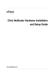
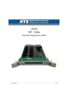
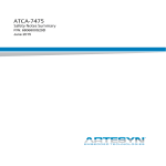
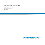
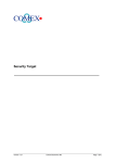
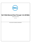
RTM-ATCA-9305 I/O
Installation and Use
The information in this manual has been checked and is believed to be accurate and reliable.
HOWEVER, NO RESPONSIBILITY IS ASSUMED BY EMERSON NETWORK POWER, EMBEDDED
COMPUTING FOR ITS USE OR FOR ANY INACCURACIES. Specifications are subject to change
without notice. EMERSON DOES NOT ASSUME ANY LIABILITY ARISING OUT OF USE OR
OTHER APPLICATION OF ANY PRODUCT, CIRCUIT, OR PROGRAM DESCRIBED HEREIN. This
document does not convey any license under Emerson patents or the rights of others.
Emerson. Consider It Solved is a trademark, and Business-Critical Continuity, Emerson
Network Power, and the Emerson Network Power logo are trademarks and service marks
of Emerson Electric Co.
All other brand or product names may be trademarks or registered trademarks of their respective holders.
Copying and distribution of this information is prohibited.
© Copyright Emerson Network Power, Embedded Computing, Inc. All rights reserved.
Contents
Declaration of Conformity...........................................................5
About this Manual.......................................................................6
Abbreviations...............................................................................................6
Conventions.................................................................................................7
Summary of Changes....................................................................................8
Comments and Suggestions.........................................................................8
Safety Notes................................................................................9
Sicherheitshinweise..................................................................12
Introduction..............................................................................15
Features......................................................................................................15
Standard Compliances................................................................................15
Mechanical Data.........................................................................................16
Ordering Information..................................................................................16
Board Identification....................................................................................17
Hardware Preparation and Installation......................................20
Unpacking and Inspecting the Board..........................................................20
Environmental Requirements......................................................................20
Power Requirements...................................................................................22
Installing and Removing the RTM................................................................22
Installing the RTM............................................................................23
Removing the RTM..........................................................................26
Installing and Removing SFP/SFP+ Modules................................................27
Installing an SFP/SFP+ Module.........................................................27
Removing an SFP/SFP+ Module........................................................28
LEDs and I/O Interfaces..............................................................29
Main Board Layout......................................................................................29
Sub-board Layout.......................................................................................30
On-board Connectors.................................................................................31
10010926-03 | RTM-ATCA-9305 I/O |
iii
Face Plate....................................................................................................32
Port Pin Assignments..................................................................................35
SFP/SFP+..........................................................................................35
COM Ports.......................................................................................37
Status LEDs.................................................................................................37
Functional Description..............................................................39
Block Diagram............................................................................................39
Ethernet Switch..........................................................................................40
10-Gigabit Ethernet Transceiver..................................................................41
Module Management Controller.................................................................41
Serial Debug Port........................................................................................42
SIPL Protocol...............................................................................................42
Emerson OEM Commands..........................................................................42
I2C Read SFP Register.......................................................................43
I2C Write SFP Register......................................................................43
Drive EEPROM..................................................................................44
Un Drive EEPROM............................................................................44
Related Documentation............................................................45
Emerson Documents..................................................................................45
Related Specifications.................................................................................45
iv | RTM-ATCA-9305 I/O | 10010926-03
Declaration of Conformity
10010926-03 | RTM-ATCA-9305 I/O |
5
About this Manual
This manual has the following sections:
Introduction on page 15 gives an overview of the features of the product, including mechanical, label, and
ordering information.
Safety Notes on page 9 lists the safety notes that should be observed when handing or operating the
product.
Sicherheitshinweise on page 12 lists the German translation of the safety notes.
Hardware Preparation and Installation on page 20 provides information on the environmental and power
requirements, as well as procedures for the installation and removal of the product.
LEDs and I/O Interfaces on page 29 describes the LEDs, I/O interfaces and pin assignments, as well as the
board layout.
Functional Description on page 39 describes the main components found on the board.
Related Documentation on page 45 provides a list of related Emerson documentation, including specifications
related to the product.
Abbreviations
This document uses the following terms and abbreviations:
Abbreviation
Definition
ATCA
Advanced Telecommunications Computing Architecture
CSA
Canadian Standards Association
EMC
Electromagnetic Compatibility
ETSI
European Telecommunications Standards Institute
FCC
Feder Communications Commission
GbE
Gigabit Ethernet
IEC
International Electrotechnical Commission
IPMB
Intelligent Platform Management Bus
IPMC
Intelligent Platform Management Controller
IPMI
Intelligent Platform Management Interface
NEBS
Network Equipment-Building System
PCIe
PCI Express
PICMG
PCI Industrial Computer Manufacturers Group
6 | RTM-ATCA-9305 I/O | 10010926-03
About this Manual
Abbreviation
Definition
RoHS
Restriction of Hazardous Substances
RTM
Rear Transition Module
SFP/SFP+
Small Form Factor Optical Transceiver Module
SGMII
Serial Gigabit Media Independent Interface
UL
Underwriters Laboratories Inc.
WEEE
Waste Electrical and Electronic Equipment
XAUI
10 GbE Attachment Unit Interface
Conventions
The following table describes the conventions used throughout this manual.
Notation
Description
0x00000000
Typical notation for hexadecimal numbers (digits are 0
through F), for example used for addresses and offsets
0b0000
Same for binary numbers (digits are 0 and 1)
bold
Used to emphasize a word
Screen
Used for on-screen output and code-related elements or
commands in body text
Courier + Bold
Used to characterize user input and to separate it from
system output
Reference
Used for references and for table and figure descriptions
File > Exit
Notation for selecting a submenu
[text]
Notation for software buttons to click on the screen and
parameter description
...
Repeated item for example node 1, node 2, ..., node 12
.
Omission of information from example/command that is
not necessary at the time being
.
.
10010926-03 | RTM-ATCA-9305 I/O |
7
About this Manual
Notation
Description
..
Ranges, for example: 0..4 means one of the integers
0,1,2,3, and 4 (used in registers)
|
Logical OR
Indicates a hazardous situation which, if not avoided, could
result in death or serious injury
Indicates a hazardous situation which, if not avoided, may
result in minor or moderate injury
Indicates a potentially hazardous situation which, if not
avoided, may result in property damage
Summary of Changes
This is the first edition of the RTM-ATCA-9305 Installation and Use.
Part Number
Publication Date
Description
10010926-00
October 2008
Design availability version
10010926-01
May 2009
Updated face plate graphic, updated functional
description chapter, added board identification
section; Added Declaration of Conformity
10010926-02
June 2009
Added temperature critical spot
10010926-03
June 2010
Updated IPMI specifications in Features and Module
Management Controller sections. Updated IPMI
Sensors table. Updated Emerson OEM Commands
section.
Comments and Suggestions
We welcome and appreciate your comments on our documentation. We want to know what you think about
our manuals and how we can make them better.
Mail comments to us by filling out the following online form:
http://www.emersonnetworkpowerembeddedcomputing.com ➤ Contact Us ➤ Online Form
In “Area of Interest” select “Technical Documentation". Be sure to include the title, part number, and revision
of the manual and tell us how you used it.
8 | RTM-ATCA-9305 I/O | 10010926-03
Safety Notes
This section provides warnings that precede potentially dangerous procedures throughout this manual. Instructions contained in the warnings must be followed during all phases of operation, service, and repair of
this equipment. You should also employ all other safety precautions necessary for the operation of the
equipment in your operating environment. Failure to comply with these precautions or with specific warnings
elsewhere in this manual could result in personal injury or damage to the equipment.
Emerson intends to provide all necessary information to install and handle the product in this manual. Because
of the complexity of this product and its various uses, we do not guarantee that the given information is
complete. If you need additional information, ask your Emerson representative.
The product has been designed to meet the standard industrial safety requirements. It must not be used except
in its specific area of office telecommunication industry and industrial control.
Only personnel trained by Emerson or persons qualified in electronics or electrical engineering are authorized
to install, remove or maintain the product.
The information given in this manual is meant to complete the knowledge of a specialist and must not be used
as replacement for qualified personnel.
Keep away from live circuits inside the equipment. Operating personnel must not remove equipment covers.
Only Factory Authorized Service Personnel or other qualified service personnel may remove equipment covers
for internal subassembly or component replacement or any internal adjustment.
Do not install substitute parts or perform any unauthorized modification of the equipment or the warranty
may be voided. Contact your local Emerson representative for service and repair to make sure that all safety
features are maintained.
EMC
This equipment has been tested and found to comply with the limits for a Class A digital device, pursuant to
Part 15 of the FCC Rules, EN55022. These limits are designed to provide reasonable protection against harmful
interference when the equipment is operated in a commercial environment. This equipment generates, uses,
and can radiate radio frequency energy and, if not installed and used in accordance with the instruction manual, may cause harmful interference to radio communications.
Operation of this equipment in a residential area is likely to cause harmful interference in which case the user
will be required to correct the interference at his own expense. Changes or modifications not expressly approved
by Emerson Network Power could void the user's authority to operate the equipment. Board products are
tested in a representative system to show compliance with the above mentioned requirements. A proper installation in a compliant system will maintain the required performance. Use only shielded cables when connecting peripherals to assure that appropriate radio frequency emissions compliance is maintained.
Operation
Product Damage
10010926-03 | RTM-ATCA-9305 I/O |
9
Safety Notes
High humidity and condensation on surfaces cause short circuits.
Do not operate the product outside the specified environmental limits. Make sure the product is completely
dry and there is no moisture on any surface before applying power.
Hot Swap
Data Loss
Removing the product with the blue LED still blinking causes data loss.
Wait until the blue LED is permanently illuminated before removing the product.
Product Damage
Installing or removing the product while power is applied damages the product.
Before removing the RTM from a powered system, power down the slot and the front blade’s payload by
opening the lower handle of the front blade and wait until the blue LED is permanently ON.
Installation
Damage of Circuits
Electrostatic discharge and incorrect installation and removal of the product can damage circuits or
shorten their life.
Before touching the product make sure that your are working in an ESD-safe environment or wear an ESD
wrist strap or ESD shoes. Hold the product by its edges and do not touch any components or circuits.
Damage of the RTM
Incorrect installation of the RTM can cause damage of the RTM.
Only use handles when installing/removing the RTM to avoid damage/deformation to the face plate and/or
PCB.
Damage of RTM and Front Blade
Installing the RTM with other blades may damage the RTM and the front blade.
Only install the RTM with the ATCA-9305 blade.
SFP/SFP+ Modules
Personal Injury and Damage of the RTM and SFP/SFP+ Modules
Installing and using SFP/SFP+ modules which are not fully certified and which do not meet all relevant
safety standards may damage the RTM and the SFP/SFP+ modules and may lead to personal injury.
Only use and install SFP/SFP+ modules which are fully certified and which meet all relevant safety standards.
10 | RTM-ATCA-9305 I/O | 10010926-03
Safety Notes
Personal Injury
Optical SFP/SFP+ modules may be classified as laser products. When installing and using any of these
SFP/SFP+ modules, the regulations which correspond to the respective laser class apply to the whole RTM.
Not complying to these regulations may lead to personal injury.
When installing and using optical SFP/SFP+ modules which are classified as laser products, make sure to
comply to the respective regulations.
Eye Damage
Optical SFP/SFP+ modules may emit laser radiation when no cable is connected. This laser radiation is
harmful to your eyes.
Do not look into the optical lens at any time.
SFP/SFP+ Module Damage
The optical port plug protects the sensitive optical fibres against dirt and damage. Dirt and damage can
render the SFP/SFP+ module inoperable.
Only remove the optical plug when you are ready to connect a cable to the SFP/SFP+ module. When no
cable is connected, cover the port with an optical port plug.
Environment
Environmental Damage
Improperly disposing of used products may harm the environment.
Always dispose of used products according to your country’s legislation and manufacturer’s instructions.
10010926-03 | RTM-ATCA-9305 I/O |
11
Sicherheitshinweise
Dieses Kapitel enthält Hinweise, die potentiell gefährlichen Prozeduren innerhalb dieses Handbuchs vorrangestellt sind. Beachten Sie unbedingt in allen Phasen des Betriebs, der Wartung und der Reparatur des
Systems die Anweisungen, die diesen Hinweisen enthalten sind. Sie sollten außerdem alle anderen Vorsichtsmaßnahmen treffen, die für den Betrieb des Systems innerhalb Ihrer Betriebsumgebung notwendig sind.
Wenn Sie diese Vorsichtsmaßnahmen oder Sicherheitshinweise, die an anderer Stelle diese Handbuchs enthalten
sind, nicht beachten, kann das Verletzungen oder Schäden am System zur Folge haben.
Emerson ist darauf bedacht, alle notwendigen Informationen zum Einbau und zum Umgang mit dem System
in diesem Handbuch bereit zu stellen. Da es sich jedoch bei dem System um ein komplexes Produkt mit
vielfältigen Einsatzmöglichkeiten handelt, können wir die Vollständigkeit der im Handbuch enthaltenen Informationen nicht garantieren. Falls Sie weitere Informationen benötigen sollten, wenden Sie sich bitte an die
für Sie zuständige Geschäftsstelle von Emerson.
Das Produkt erfüllt die für die Industrie geforderten Sicherheitsvorschriften und darf ausschließlich für Anwendungen in der Telekommunikationsindustrie, im Zusammenhang mit Industriesteuerungen und in der Entwicklung verwendet werden.
Einbau, Wartung und Betrieb dürfen nur von durch Emerson ausgebildetem oder im Bereich Elektronik oder
Elektrotechnik qualifiziertem Personal durchgeführt werden.
Die in diesem Handbuch enthaltenen Informationen dienen ausschließlich dazu, das Wissen von Fachpersonal
zu ergänzen, können dieses jedoch nicht ersetzen.
Halten Sie sich von stromführenden Leitungen innerhalb des Systems fern. Entfernen Sie auf keinen Fall die
Systemabdeckung. Nur werksseitig zugelassenes Wartungspersonal oder anderweitig qualifiziertes
Wartungspersonal darf die Systemabdeckung entfernen, um Systemkomponenten zu ersetzen oder andere
Anpassungen vorzunehmen.
Installieren Sie keine Ersatzteile oder führen Sie keine unerlaubten Veränderungen am System durch, sonst
verfällt die Garantie. Wenden Sie sich für Wartung oder Reparatur bitte an die für Sie zuständige Geschäftsstelle
von Emerson. So stellen Sie sicher, dass alle sicherheitsrelevanten Aspekte beachtet werden.
EMV
Das Produkt wurde getestet und erfüllt die für digitale Geräte der Klasse A gültigen Grenzwerte gemäß den
FCC-Richtlinien Abschnitt 15 bzw. EN 55022 Klasse A. Diese Grenzwerte sollen einen angemessenen Schutz
vor Störstrahlung beim Betrieb des Produkts in Geschäfts-, Gewerbe- sowie Industriebereichen gewährleisten.
Das Produkt arbeitet im Hochfrequenzbereich und erzeugt Störstrahlung. Bei unsachgemäßem Einbau und
anderem als in diesem Handbuch beschriebenen Betrieb können Störungen im Hochfrequenzbereich auftreten.
Diese Einrichtung kann im Wohnbereich Funkstörungen verursachen; in diesem Fall kann vom Betreiber verlangt
werden, angemessene Maßnahmen durchzuführen und dafür aufzukommen. Änderungen, die nicht ausdrücklich
von Emerson erlaubt sind, können Ihr Recht das System zu betreiben zunichte machen. Um die Einhaltung
der oben genannten Richtlinien zu beweisen werden die Boards in Referenzsystemen getestet. Wenn Sie das
Board gemäß der Anleitung in ein System einbauen, das diese Richtlinien einhält, wird das gewünschte
12 | RTM-ATCA-9305 I/O | 10010926-03
Sicherheitshinweise
Ergebnis erreicht. Benutzen Sie zum Anschließen von Peripheriegeräten ausschließlich abgeschirmte Kabel.
So stellen Sie sicher, dass ausreichend Schutz vor Störstrahlung vorhanden ist.
Betrieb
Beschädigung des Produktes
Hohe Luftfeuchtigkeit und Kondensat auf den Oberflächen der Produkte kann zu Kurzschlüssen führen.
Betreiben Sie die Produkte nur innerhalb der angegebenen Grenzwerte für die relative Luftfeuchtigkeit
und Temperatur und stellen Sie vor dem Einschalten des Stroms sicher, dass sich auf den Produkten kein
Kondensat befindet.
Hot Swap
Datenverlust
Wenn Sie das Produkt ausbauen obwohl die blaue Hot-Swap-LED noch blinkt, kann dies zu Datenverlust
führen.
Warten Sie daher bis die blaue LED durchgehend leuchtet, bevor Sie das Produkt ausbauen.
Beschädigung des Produktes
Wenn Sie das RTM ausbauen während das System läuft und die blaue LED auf dem Front Board noch blinkt,
können Daten verloren gehen.
Schalten SIe deshalb vor dem Ausbau des RTMs den Slot, in dem es sich befindet, ab und fahren Sie die
Payload des Front Boards herunter indem Sie den unteren Griff des Front Boards öffnen und warten bis die
blaue LED leuchtet ohne zu blinken.
Installation
Beschädigung von Schaltkreisen
Elektrostatische Entladung und unsachgemäßer Ein- und Ausbau von Blades/RTMs kann Schaltkreise
beschädigen oder ihre Lebensdauer verkürzen.
Bevor Sie Blades/RTMs oder elektronische Komponenten berühren, vergewissern Sie sich, daß Sie in einem
ESD-geschützten Bereich arbeiten.
Beschädigung des RTMs
Fehlerhafte Installation des RTMs kann zu einer Beschädigung des RTMs führen.
Verwenden Sie die Handles, um das RTM zu installieren/deinstallieren. Auf diese Weise vermeiden Sie,
dass das Face Plate oder die Platine deformiert oder zerstört wird.
Beschädigung des Produktes und von Zusatzmodulen
10010926-03 | RTM-ATCA-9305 I/O |
13
Sicherheitshinweise
Fehlerhafter Ein- oder Ausbau von Zusatzmodulen kann zur Beschädigung des Produktes und der Zusatzmodule führen.
Lesen Sie daher vor dem Ein- und Ausbau von Zusatzmodulen die zugehörige Dokumentation und verwenden
Sie angemessenes Werkzeug.
SFP/SFP+ Modules
Gefahr von Verletzungen sowie von Beschädigung des RTMs und SFP/SFP+-Modulen
Die Installation und der Betrieb von SFP/SFP+-Modulen, welche nicht zertifiziert sind und welche nicht den
Sicherheitsstandards entsprechen, kann Verletzungen zur Folge haben sowie zur Beschädigung des RTMs
und von SFP/SFP+-Modulen führen.
Verwenden Sie daher nur SFP/SFP+-Module, die zertifiziert sind und die den Sicherheitsstandards
entsprechen.
Verletzungsgefahr
Optische SFP/SFP+-Module können als Laserprodukte klassifiziert sein. Wenn Sie solche SFP/SFP+-Module
installieren und betreiben, so gelten die entsprechenden Bestimmungen für Laserprodukte für das gesamte
RTM. Werden diese Bestimmungen nicht eingehalten, so können körperliche Verletzungen die Folge sein.
Wenn Sie SFP/SFP+-Module betreiben, welche als Laserprodukte klassifiziert sind, so stellen Sie sicher, dass
die entsprechenden Bestimmungen für Laserprodukte eingehalten werden.
Verletzungsgefahr der Augen
Optische SFP/SFP+-Module können Laserstrahlen aussenden, wenn kein Kabel angeschlossen ist.
Vermeiden Sie es daher, direkt in die Öffnung eines SFP/SFP+-Moduls zu sehen, um Verletzungen der Augen
zu vermeiden.
Beschädigung von SFP/SFP+-Modulen
Die Schutzkappe eines SFP/SFP+-Modules dient dazu, die sensible Optik des SFP/SFP+-Modules gegen
Staub und Schmutz zu schützen.
Entfernen Sie die Schutzkappe nur dann, wenn Sie beabsichtigen, ein Kabel anzuschließen. Andernfalls
belassen Sie die Schutzkappe auf dem SFP/SFP+-Modul.
Umweltschutz
Entsorgen Sie alte Batterien und/oder Blades/Systemkomponenten/RTMs stets gemäß der in Ihrem Land
gültigen Gesetzgebung, wenn möglich immer umweltfreundlich.
14 | RTM-ATCA-9305 I/O | 10010926-03
Introduction
This chapter provides an overview of the features of the RTM, standard compliances, ordering information,
and other board-related information.
Features
The RTM-ATCA-9305 is a rear transition module as defined in PICMG 3.0 Revision 2.0 AdvancedTCA Base Specification . It provides several Ethernet interfaces connected to the front board via the Zone 3 connector.
The RTM is available in two configurations:
• Configuration 1 (C0010716-00) provides 18 Gigabit Ethernet ports to the ATCA-9305.
• Configuration 2 (C0010717-00) provides 12 Gigabit Ethernet ports and two 10-Gigabit Ethernet ports.
Both configurations have the following features:
• Module management according to IPMI specification 1.5 Revision 1.1
• Two reset buttons on the face plate: one for resetting the front board payload, the other for resetting the
module management controller of the RTM
• Two mini USB ports on the face plate to monitor the RTM and the front board
• On-board I/O power converters
Standard Compliances
The product meets the standards listed below.
Standard
UL 60950-1
Description
Legal safety requirements
EN 60950-1
IEC 60950-1
CAN/CSA C22.2 No 60950-1
CISPR 22
EMC requirements (legal) on system level
CISPR 24
(predefined Emerson system)
EN 55022
EN 55024
FCC Part 15
Industry Canada ICES-003
10010926-03 | RTM-ATCA-9305 I/O |
15
Introduction
Standard
Description
VCCI Japan
AS/NZS CISPR 22
EN 300 386
The product has been partially tested to comply with NEBS Standard GR-1089 CORE, NEBS Standard GR-63CORE, ETSI EN 300019 series, and PICMG 3.0.
This product has been designed to meet:
• The directive on the restriction of the use of certain hazardous substances in electrical and electronic
equipment (RoHS Directive 2002/95/EC).
• The directive on waste electrical and electronic equipment (WEEE Directive 2002/96/EC).
Mechanical Data
This section lists the physical dimensions and weight of the RTM.
Feature
Value
Physical dimension of the main board
322.25 mm x 125.76 mm
Physical dimension of the mezzanine board
312.24mmx 94.44mm
Weight of RTM
0.580 kg
Ordering Information
When ordering accessories, use the following information:
Table 1: RTM Variants
Model/Part Number
Description
C0010716-00
Eighteen 1-Gigabit SFP ports
C0010717-00
Twelve 1-Gigabit SFP ports plus two 10-Gigabit SFP+ ports
16 | RTM-ATCA-9305 I/O | 10010926-03
Introduction
Table 2: SFP Module
Type
Part Number
Description
Optical
Avago SFP_AFBR-57L5APZ
SINGLE FORM-FACTOR PLUGGABLE - 850NM, 1000BASE-SX, LC
CONNECTOR
Avago AFBR-5715LZ
Finisar FTLF8519P2BNL
Copper
Avago ABCU-5710RZ
SINGLE FORM-FACTOR PLUGGABLE, 1000BASE-T Copper, RJ-45
CONNECTOR
Table 3: SFP+ Module
Type
Model/Part Number
Description
Optical
Finisar FTLX8571D3BCL
SFP PLUS MULTIMODE-850NM, 10 GIGABIT ETHERNET-SR, LC CONNECTOR
JDSU PLRXPL-SC-S43-21-N
SFP PLUS MULTIMODE-850NM, 10 GIGABIT ETHERNET-SR/SW, LC
CONNECTOR
The SFP modules can be in combinations of 1000BASE-T, 1000BASE-SX, or 1000BASE-LX.
Boards are shipped without the SFP/SFP+ plug-in modules installed in the cage. You can purchase and install
any combination of copper or optical SFP modules on the RTM. For the 10-Gigabit SFP+ ports, use optical SFP+
modules.
Board Identification
This section shows the product label and assembly number, and indicates where the label is located on the
product.
Labels
The following graphics show the Product ID and Serial Number labels, and their location on the board.
Figure 1: Product ID Label
10010926-03 | RTM-ATCA-9305 I/O |
17
Introduction
Figure 2: Serial Number Label
Figure 3: Location of the Label
Assembly Number
Configuration
Assembly Number
Configuration 1 (18 1-Gigabit SFP ports)
C0010716-00
Configuration 2 (12 1-Gigabit SFP ports and two 10-Gigabit C0010717-00
SFP+ ports)
18 | RTM-ATCA-9305 I/O | 10010926-03
Introduction
Note: The assembly number also serves as the RTM model number.
10010926-03 | RTM-ATCA-9305 I/O |
19
Hardware Preparation and Installation
This chapter discusses applicable environmental and power requirements, the installation and removal of the
RTM, and the installation and removal of the SFP/SFP+ module.
Unpacking and Inspecting the Board
Attention: Damage of Circuits
Electrostatic discharge and incorrect installation and removal of the product can damage circuits
or shorten their life.
Before touching the product make sure that your are working in an ESD-safe environment or wear
an ESD wrist strap or ESD shoes. Hold the product by its edges and do not touch any components
or circuits.
1. Make sure that you have received all the items of your shipment.
2. Check for damage and report any damage or differences to the customer service.
Tip: The product is thoroughly inspected before shipment. If any damage occurred during
transportation or any items are missing, contact customer service immediately.
3. Remove the desiccant bag that shipped with the module, and then dispose of it according to your country's
legislation.
Environmental Requirements
Make sure that the board, when operated in your particular system configuration, meets the environmental
requirements specified below.
Operating temperatures refer to the temperature of the air circulating around the RTM, and not to
component temperatures.
If you integrate the RTM in your own non-Emerson system, contact your local sales representative for
further safety information.
Requirement
Temperature
Operating
Non-Operating
+5ºC (41ºF) to +40ºC (104ºF) (normal operation) -40ºC (-40ºF) to +70ºC (158ºF)
-5ºC (23ºF) to +55ºC (131ºF) (exceptional opera- This may be further limited by installed accestion)
sories.
Temperature Change
20 | RTM-ATCA-9305 I/O | 10010926-03
+/- 0.25ºC/min
+/- 0.25ºC/min
Hardware Preparation and Installation
Requirement
Operating
Non-Operating
Relative Humidity
5% to 95% non-condensing according to Emerson-internal environmental requirements
5% to 95% non-condensing according to
Emerson internal environmental requirements
Vibration
0.1 g from 5 to 100 Hz and back to 5 Hz at a rate
2
5-20 Hz at 0.01 g /Hz
of 0.1 octave/minute
20-200 Hz at -3.0 dB/octave
2
3
Random 5-20 Hz at 1 m /Sec
2
Random 20-200 Hz at -3 m/Sec
Shock
2
Half-sine, 11 m/Sec, 30 mSec/Sec
Module-level packaging
2
Half-sine, 6 msec at 180 m/Sec
Free Fall
-
1,200 mm/all edges and corners
1.0 m (packaged)
100 mm (unpacked)
Attention: Product Damage
High humidity and condensation on surfaces cause short circuits.
Do not operate the product outside the specified environmental limits. Make sure the product is
completely dry and there is no moisture on any surface before applying power.
Critical Temperature Spot
During the safety qualification of this board, the location shown in the figure below was identified as a critical
temperature spot. To guarantee proper board operation and ensure safety, make sure that the temperature
at the specified location is not exceeded. If not stated otherwise, the temperature should be measured by
placing a sensor at the critical temperature spot.
10010926-03 | RTM-ATCA-9305 I/O |
21
Hardware Preparation and Installation
Figure 4: Critcal Temperature Spot
Power Requirements
The RTM has a maximum power dissipation of 30 W for a combined 12 V payload and 3.3 V management
supply.
Installing and Removing the RTM
Attention: Damage of RTM and Front Blade
The RTM can be installed into a powered or non-powered system.
Installing the RTM with other blades may damage the RTM and the front blade.
Only install the RTM with the Emerson ATCA-9305 blade.
Damage of Circuits
22 | RTM-ATCA-9305 I/O | 10010926-03
Hardware Preparation and Installation
Electrostatic discharge and incorrect installation and removal of the product can damage circuits
or shorten their life.
Before touching the product, make sure that you are working in an ESD-safe environment or wear
an ESD wrist strap or ESD shoes. Hold the product by its edges and do not touch any components
or circuits.
Installing the RTM
You can install the RTM whether or not the front blade is installed.
Front Blade is Installed
Use this procedure to install the RTM when the front blade is installed.
This procedure assumes that your system is powered. If your system is unpowered, disregard the blue LED
and skip the respective step.
1. Locate the slot where the RTM is to be installed into the shelf's rear, which must be the same as that of the
front blade.
2. Open the lower handle of the front blade to power down its payload.
The blue LED on the front blade starts to flash. This indicates that the front blade is informing the shelf
manager that it wants to power down its payload.
3. Wait until the blue LED on the front blade is lit.
When the blue LED is lit, the payload is powered down.
4. Make sure that the top and bottom handles of the RTM are in an outward position by squeezing the lever
and latch together.
5. Insert the RTM into the shelf by placing the top and bottom edges in the card guides of the slot.
6. Slide the RTM into the slot.
7. Apply equal and steady pressure to the RTM to carefully slide it into the shelf until you feel resistance.
10010926-03 | RTM-ATCA-9305 I/O |
23
Hardware Preparation and Installation
8. Continue to gently push the RTM until the RTM connectors engage.
9. Squeeze the lever and latch together, and then hook the lower and upper handle into the shelf rail recesses.
10. Fully insert the RTM and lock it to the shelf by pressing the two components of the lower and upper handles
together, and then turning the handles toward the face plate.
If your shelf is powered, as soon as the RTM is connected to the front blade, the blue LED lights up and will
remain lit until the lower handle of the RTM and the lower handle of the front blade are closed.
11. Close the lower handle of the front blade so that both payloads of the RTM and front blade are powered
up.
The blue LEDs on both the front blade and RTM start flashing. This indicates that the front blade is informing
the shelf manager that it wants to power up the payload of both the front blade and RTM.
12. Tighten the face plate screws on the RTM.
13. Wait until the blue LEDs on the front blade and the RTM are not lit.
A blue LED that is not lit indicates that the payload of the front blade and the RTM has been powered up
and is active.
14. Plug the interface cable into the face plate connectors, if applicable.
Front Blade is not Installed
Use this procedure to install the RTM when the front blade is not installed.
1. Locate the slot where the RTM is to be installed into the shelf's rear, which must be the same as that of the
front blade.
2. Make sure that the top and bottom handles of the RTM are in an outward position by squeezing the lever
and latch together.
24 | RTM-ATCA-9305 I/O | 10010926-03
Hardware Preparation and Installation
3. Insert the RTM into the shelf by placing the top and bottom edges in the card guides of the slot.
4. Slide the RTM into the slot.
5. Apply equal and steady pressure to the RTM to carefully slide it into the shelf until you feel resistance.
6. Continue to gently push the RTM until the RTM connectors engage.
7. Squeeze the lever and latch together, and then hook the lower and upper handle into the shelf rail recesses.
8. Fully insert the RTM and lock it to the shelf by pressing the two components of the lower and upper handles
together, and then turning the handles toward the face plate.
9. Tighten the face plate screws on the RTM.
10. Insert the front blade on the system's front, into the same slot as the RTM.
For more information on installing the front blade, see ATCA-9305 User's Manual.
As soon as the front blade is connected to the backplane, the blue LEDs on the front blade and the RTM
light up permanently. This indicates that the IPMC of the front blade and the MMC of the RTM are powered
up.
10010926-03 | RTM-ATCA-9305 I/O |
25
Hardware Preparation and Installation
11. Close the handles of the front blade.
The blue LEDs on the front blade and the RTM start flashing. This indicates that the front blade is informing
the shelf manager that it wants to power up the payload of both the front blade and the RTM.
12. Tighten the face plate screws on the front blade.
13. Wait until the blue LEDs on the front blade and the RTM are not lit.
A blue LED that is not lit indicates that the payload of the front blade and the RTM has been powered up
and is active.
14. Plug the interface cable into the face plate connectors, if applicable.
Removing the RTM
This procedure assumes that your system is powered. If your system is unpowered, disregard the blue LED
and skip the respective step.
1. Unlatch the lower handle outward by squeezing the lever and latch together, and then turning the handle
outward until you feel a resistance.
Tip: Do not rotate the handle fully outwards.
The blue LED blinks indicating that the shelf manager is informed of the desire of the front blade to power
down the payload of both the front blade and RTM, and that the power-down process is on-going.
2. Wait until the blue LEDs on the front blade and RTM are permanently lit.
A permanently lit LED indicates that the payload of both the front blade and RTM has been powered down.
Attention: Data Loss
Removing the product with the blue LED still blinking causes data loss.
Wait until the blue LED is permanently illuminated before removing the product.
Product Damage
26 | RTM-ATCA-9305 I/O | 10010926-03
Hardware Preparation and Installation
Installing or removing the product while power is applied damages the product.
Before removing the RTM from a powered system, power down the slot and the front blade’s
payload by opening the lower handle of the front blade and wait until the blue LED is permanently ON.
3. Unlatch the upper handle, and then rotate both handles fully outward.
4. Remove the interface cables from the face plate connectors, if applicable.
5. Loosen the screws on the RTM face plate.
6. Remove the RTM from the slot.
Installing and Removing SFP/SFP+ Modules
This section describes how to install and remove SFP and SFP+ modules.
Attention: Eye Damage
Optical SFP/SFP+ modules may emit laser radiation when no cable is connected. This laser radiation
is harmful to your eyes.
Do not look into the optical lens at any time.
Personal Injury and Damage of the RTM and SFP/SFP+ Modules
Installing and using SFP/SFP+ modules which are not fully certified and which do not meet all relevant
safety standards may damage the RTM and the SFP/SFP+ modules, and may lead to personal injury.
Only use and install SFP/SFP+ modules which are fully certified and which meet all relevant safety
standards.
Personal Injury
Optical SFP/SFP+ modules may be classified as laser products. When installing and using any of
these SFP/SFP+ modules, the regulations which correspond to the respective laser class apply to
the whole RTM. Not complying to these regulations may lead to personal injury.
When installing and using optical SFP/SFP+ modules which are classified as laser products, make
sure to comply to the respective regulations.
Installing an SFP/SFP+ Module
1. Slide the SFP/SFP+ module into the slot until it locks into position.
Notes:
• When inserting an SFP module, make sure the connector faces down.
10010926-03 | RTM-ATCA-9305 I/O |
27
Hardware Preparation and Installation
• When inserting an SFP+ module, make sure the connector faces up.
2. Remove the optical port plug.
Attention: SFP/SFP+ Module Damage
The optical port plug protects the sensitive optical fibres against dirt and damage.
Dirt and damage can render the SFP/SFP+ module inoperable.
Only remove the optical plug when you are ready to connect a cable to the SFP/SFP+ module.
When no cable is connected, cover the port with an optical port plug.
3. Connect the network cable to the SFP/SFP+ module.
Removing an SFP/SFP+ Module
1. Remove any connected cable from the SFP/SFP+ module.
2. Open the SFP/SFP+ latch.
Note that the latch mechanism of your SFP/SFP+ module may be slightly different compared to the latch
shown in the figure above.
3. Grasp the SFP/SFP+ module, and then carefully slide it out of the slot.
4. Cover the optical port with the optical port plug.
Attention: SFP/SFP+ Module Damage
The optical port plug protects the sensitive optical fibres against dirt and damage.
Dirt and damage can render the SFP/SFP+ module inoperable.
Only remove the optical plug when you are ready to connect a cable to the SFP/SFP+ module.
When no cable is connected, cover the port with an optical port plug.
28 | RTM-ATCA-9305 I/O | 10010926-03
LEDs and I/O Interfaces
Main Board Layout
10010926-03 | RTM-ATCA-9305 I/O |
29
LEDs and I/O Interfaces
Sub-board Layout
30 | RTM-ATCA-9305 I/O | 10010926-03
LEDs and I/O Interfaces
Note: The SFP+ ports are only available in Configuration 2.
On-board Connectors
The RTM provides I/O interfaces to the ATCA-9305. The port assignments are detailed below.
Table 4: Main Board Port Assignments
Location
Function
P1
Connects to J33 on ATCA-9305
P7
Connects to J31 on ATCA-9305
1
U17
BCM8725 Dual 10Gb PHY
Connects to the XAUI ports on ATCA-9305
P8
Connects to J30 on ATCA-9305
P2
RP COM
RTM console port
1
SFP+ Port 1
1
P5
SFP+ Port 2
P3
HOST COM
P6
Front board console
P4
Searay connector
SW2
RTM IPMI reset button
U10
Marvell 98DX5126 Ethernet switch
SW1
Front blade payload reset button
1 Applicable to Configuration 2 only.
Table 5: Mezzanine Board Port Assignments
Location
Function
P1 to P12
SFP ports
These ports provide 1-Gigabit Ethernet connection.
10010926-03 | RTM-ATCA-9305 I/O |
31
LEDs and I/O Interfaces
Location
Function
P13, P14
SFP+ ports
These ports provide 10-Gigabit Ethernet connection. These are only available in
Configuration 2.
Face Plate
Figure 5: Face Plate for Configuration 1
32 | RTM-ATCA-9305 I/O | 10010926-03
LEDs and I/O Interfaces
Table 6: Configuration 1 Interfaces
Item
Description
Ports 1 to 18
These are SFP ports that provide 1 Gb Ethernet access.
OOS
Out of Service LED
2
In Service LED
RP COM
This is a mini USB port that can be used to monitor the RTM. (Connected to the IPMI
controller of RTM).
HOST COM
This is mini USB port that can be used to monitor the front blade. (Connected to the
console of MPC8548 on front board).
BRD RST
This resets the RTM and the front blade payload.
IPMI RST
This resets the MMC on the RTM.
H/S
Hot Swap LED
10010926-03 | RTM-ATCA-9305 I/O |
33
LEDs and I/O Interfaces
Figure 6: Face Plate for Configuration 2
Table 7: Configuration 2 Interfaces
Item
Description
Ports 1 to 12
These are SFP ports that provide 1 Gb Ethernet access.
10Gb 2, 10 Gb 1
These are SFP+ ports that provide 10 Gb Ethernet access.
OOS
Out of Service LED
2
In Service LED
34 | RTM-ATCA-9305 I/O | 10010926-03
LEDs and I/O Interfaces
Item
Description
RP COM
This is a mini USB port that can be used to monitor the RTM.
SFP+ LED
See Status LEDs on page 37.
HOST COM
This is mini USB port that can be used to monitor the front blade.
BRD RST
This resets the RTM and the front blade payload.
IPMI RST
RTM reset button
H/S
Hot Swap LED
Port Pin Assignments
SFP/SFP+
Table 8: SFP Connectors Pin Assignments
The following table lists the pin assignments for SFP connectors P1 to P12, and P15 to P20.
Pin
Signal Name
Signal Description
1
VeeT
Transmitter Ground
2
TxFault
Transmitter Fault Indication
3
TxDisable
Transmitter Disable
4
SDA
Two wire serial ID Interface
5
SCL
Two wire serial ID Interface
6
MOD_DEF0
Module Definition 0 (Grounded in module)
1
NC
Not connected
8
1
LOS
Loss of Signal
9
VeeR
Receiver Ground
RD-
Inverse Received Data
RD+
Receive Data
7
10
11
12
1
13
10010926-03 | RTM-ATCA-9305 I/O |
35
LEDs and I/O Interfaces
Pin
Signal Name
Signal Description
1
VeeR
Receiver Ground
1
VccR
Receiver Power
1
VccT
Transmitter Power
1
VeeT
Transmitter Ground
18
1
TD+
Transmitter Data
19
TD-
Inverse Transmitter Data
20
VeeT
Transmitter Ground
14
15
16
17
1 Not available in configuration 2.
Table 9: SFP+ Pin Assignments
The following table lists the pin assignments for SFP+ connectors P13 and P14.
The SFP+ connectors are only available in Configuration 2.
Pin
Signal Name
Signal Description
1
VeeT
Transmitter signal ground
2
TX_FAULT
Transmitter fault
3
TX_DISABLE
Transmitter disable
4
SDA
Two wire serial interface data line
5
SCL
Two wire serial interface clock line
6
MOD_ABS
Module absent
7
RS0
Rate select 0 - Not used
8
RX_LOS
Receiver loss of signal
9
RS1
Rate select 1 - Not used
10
VeeR
Receiver signal ground
12
RD-
Receiver data inverted
13
RD+
Receiver data
11
36 | RTM-ATCA-9305 I/O | 10010926-03
LEDs and I/O Interfaces
Pin
Signal Name
Signal Description
14
VeeR
Receiver signal ground
15
VccR
Receiver power
16
VccT
Transmitter power
17
VeeT
Transmitter signal ground
18
TD+
Transmitter data
19
TD-
Transmitter data inverted
20
VeeT
Transmitter signal ground
COM Ports
Table 10: Host/RP COM Pin Assignments, P3/P2
Pin
Signal Name
Signal Description
1
NC
Not connected
2
SIN1
Receive data
3
SOUT1
Transmit data
4
NC
Not connected
5
SGND
Signal ground
6
CGND
Chassis ground
7
8
9
Status LEDs
This section describes the status indicated by the LEDs.
10010926-03 | RTM-ATCA-9305 I/O |
37
LEDs and I/O Interfaces
Table 11: SFP+ LED, CR39 and CR40
LED Color
Status
Signal Description
Green
ON
Normal operation
OFF
TX_FAULT detected
ON
Normal operation
OFF
LOS detected
Pin
LED Color
Function
CR25
Blue
Hot swap LED
CR36
Red
Out of service (OOS)
Yellow
Table 12: Other LEDs
Amber
CR35
38 | RTM-ATCA-9305 I/O | 10010926-03
Green
In Service
Functional Description
This chapter describes the functional blocks of the RTM.
Block Diagram
The following figures show the main functional blocks of the RTM.
Figure 7: Block Diagram for Configuration 1 (18 SFPs)
10010926-03 | RTM-ATCA-9305 I/O |
39
Functional Description
Figure 8: Block Diagram for Configuration 2 (12 SFPs and 2 SFP+)
Ethernet Switch
The RTM provides an Ethernet switch using Marvell 98DX5126. This switch supports:
• 18/12 SerDes interfaces (Configuration 1/Configuration 2) on the front panel through the SFP ports.
• Two 10 Gb XAUI connections to the 10 Gb Ethernet switch (BCM56803) on the front blade.
• One single-lane PCIExpress management connection to the processor CN8548 on the front blade.
Two HyperG.Stack ports are connected to edge connector P31.
40 | RTM-ATCA-9305 I/O | 10010926-03
Functional Description
10-Gigabit Ethernet Transceiver
The RTM uses BCM8725 as a 10-Gigabit Ethernet PHY for the two XAUI ports of the front blade switch. This
allows the RTM to provide two 10 Gb (SFP+) I/O ports on the RTM face plate.
The default application of this transceiver is set to LAN.
Module Management Controller
The RTM provides an 8-bit module management controller (MMC) with 128 KB on-board programmable flash
memory to support firmware that is based on a design from Pigeon Point Systems™. The MMC is based on the
Atmega128L controller which is fully compliant to the v1.5 standard. The MMC is connected to the IPMC of
the front blade through IPMB-L.
The MMC has several sensors that provide status and are accessible via IPMI. The sensors are listed in the succeeding table.
For more information on IPMI commands, see the System Management chapter of the ATCA-9305 User's
Manual.
Table 13: IPMI Sensors
Sensor Name
Sensor Type
Sensor Number
+3.3V MP
Voltage
0x1f
+12V PP
Voltage
0x20
+3.3V PP
Voltage
0x21
+2.5V PP
Voltage
0x22
INLET temp RTM
Temperature
0x23
OUTLET temp RTM
Temperature
0x24
Switch Temp
Temperature
0x25
+1.8V PP
Voltage
0x26
+1.2V PP
Voltage
0x27
Voltage
0x28
Note: This sensor is available with I/O variant 12x1G+2x10G (Config
2) ONLY.
+1.1V PP
10010926-03 | RTM-ATCA-9305 I/O |
41
Functional Description
Serial Debug Port
The console port for the management processor is accessible via the front panel mini-B USB connector. The
supported baud rate for this port is 9600 bps.
Table 14: Serial Debug Connector
Pin
Signal
1
no connect
2
PQ_CONSOLE_RX_C
3
PQ_CONSOLE_TX_C
4
no connect
5
signal ground
6
chassis ground
7
chassis ground
The serial debug port can be used to execute raw IPMI commands in SIPL protocol.
SIPL Protocol
The IPMC supports the Serial Interface Protocol Lite (SIPL) protocol. It supports raw IPMI messages in SIPL and
handles these messages the same way as it handles IPMI messages from the IPMB-L bus, except that the replies
route to either the payload or serial debug interface. Messages are entered as case-insensitive hex-ASCII pairs,
separated optionally by a space, as shown in the following examples:
[18 00 22]<newline>
[180022]<newline>
The IPMC does not, however, support SIPL ASCII text commands, as defined by the IPMI specification.
Emerson OEM Commands
The MMC supports additional IPMI commands that are specific to the RTM. This section describes these IPMI
commands.
42 | RTM-ATCA-9305 I/O | 10010926-03
Functional Description
Table 15: Emerson OEM Commands
Command
NetFn (Request/Response)
CMD
I2C Read SFP Register, see I2C Read SFP Register on page 43
0x30/0x31
0x05
I2C Write SFP Register, see I2C Write SFP Register on page 43
0x30/0x31
0x07
Drive EEPROM, see Drive EEPROM on page 44
0x30/0x31
0x08
Un-Drive EEPROM, see Un Drive EEPROM on page 44
0x30/0x31
0x09
For more information on IPMI commands, see the System Management chapter of the ATCA-9305 User's
Manual.
I2C Read SFP Register
This command can be used to read 8 bytes of data from SFP+ Register/EEPROM.
Type
Byte
Data Field
Request Data
1
port: SFP port to read
2
I2C address: I2C address of SFP to read
3
register offset: SFP register to read
1
Completion Code
2-9
data: 8 bytes of data read
Response Data
I2C Write SFP Register
This command can be used to write 1 byte of data to an SFP+ Register/EEPROM.
Type
Byte
Data Field
Request Data
1
port: SFP port to write
2
I2C address: I2C address of SFP to write
3
register offset: SFP register to write
4
data: 1 byte of data to write
1
Completion Code
Response Data
10010926-03 | RTM-ATCA-9305 I/O |
43
Functional Description
Drive EEPROM
This command can be used to enable the level translator so that the MMC can access the SFP and other registers.
Type
Byte
Data Field
Response Data
1
Completion Code
Un Drive EEPROM
This command can be used to disable the level translator.
Type
Byte
Data Field
Response Data
1
Completion Code
44 | RTM-ATCA-9305 I/O | 10010926-03
Related Documentation
Emerson Documents
The Emerson Network Power - Embedded Computing publications listed below are referenced in this manual.
You can obtain electronic copies of these publications by contacting your local Emerson sales office or by visiting our Web site at http://emersonnetworkpower.com/embeddedcomputing:
1. Click Solution Services.
2. Click Technical Documentation Search.
Note: Check the Emerson Web Site or consult your local Emerson sales representative for release notes or errata sheets that may be applicable to the RTM or front blade.
Document Title
Publication Number
ATCA-9305 User's Manual
10009109
Related Specifications
For additional information, refer to the following table for related specifications.
Organization
PICMG
Document Title
PICMG AdvancedTCA Base Specification 3.0 Rev. 2.0 (March 18, 2005)
PICMG Specification Engineering Change Notice 3.0-2.0-001 (June 15, 2005)
PICMG Base Specification ECN-002 Revision 2.0 ATCA (March 26, 2006)
Broadcom
BCM8725 Preliminary Data Sheet (Doc. No. 8725-DS01-R, September 19, 2007)
Marvell
Prestera-DX Packet Processors Hardware Design Guide (MV-S300644-00, Rev. D, December 27, 2006)
92DX5126 Hardware Specifications (MV-S104553-00, Rev. C, March 5, 2008)
10010926-03 | RTM-ATCA-9305 I/O |
45
Index
A
E
abbreviations
list of 6
about
manual 6
assembly number 17
Ethernet switch 40
Ethernet transceiver
10-Gigabit 41
B
face plate 32
features 15
block diagram 39
board
dimensions 16
weight 16
board layout 29, 30
F
I
installing
RTM 23
SFP/SFP+ module 27
C
COM ports
pin assignment 37
commands
IPMI 42
OEM 42
comments and suggestions 8
compliances
list of 15
connectors
main board 31
mezzanine board 31
onboard 31
conventions 7
D
diagram
block 39
46 | RTM-ATCA-9305 I/O | 10010926-03
L
label
location of 17
product ID 17
serial number 17
layout
board 29, 30
LED
status description 38
M
MMC 41
O
ordering
accessories 16
board 16
SFP/SFP+ modules 16
P
pin assignment
host COM 37
RP COM 37
SFP/SFP+ 35
power
maximum dissipation 22
power dissipation 22
product label
location 17
R
references
Emerson manuals 45
specifications 45
removing
RTM 26
SFP/SFP+ module 28
requirements
environmental 20
humidity 20
operating 20
power 22
temperature 20
RTM
face plate 32
features 15
installing 23
removing 26
S
safety notes 9
sensors
type of 41
SFP/SFP+
connector pin assignment 35
SFP/SFP+ module
installing 27
removing 28
SFP/SFP+ modules
ordering 16
specifications 45
standard compliances 15
status LEDs 38
status sensors 41
U
unpacking 20
10010926-03 | RTM-ATCA-9305 I/O |
47