1
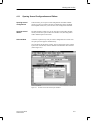
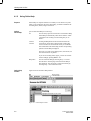
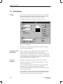
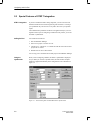
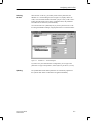
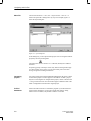
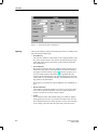
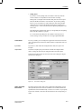
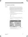
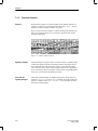
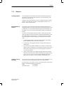
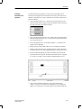
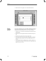
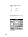
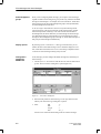
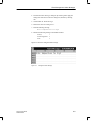
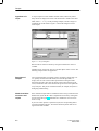
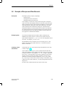
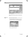
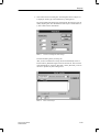
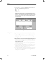
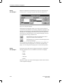
Configuring with ProTool
Example:
Creating a
project
In this example, you will create a ProTool project, including all the preliminary work for connecting the OP to the S7 PLC.
1. Create a new STEP 7 project called GETSTART in the SIMATIC Manager.
2. Select the GETSTART project. Then choose Insert → Hardware →
SIMATIC 300-Station from the menu. The SIMATIC 300-Station1 icon
appears in the SIMATIC Manager.
3. If, when you are creating the GETSTART STEP 7 project, the icon for an
MPI network does not appear, choose Insert → Subnet → MPI Network.
4. Select the SIMATIC 300-Station1 icon and choose Edit → Open Object
from the menu. The Hardware Configuration dialog box appears.
5. Open the hardware catalog by choosing View → Catalog from the menu.
6. Click in the hardware catalog on the + sign preceding SIMATIC 300, then
on the + sign preceding RACK 300. Select Mounting Rail and drag it to
the empty, blue bar of the Hardware Configuration dialog box. The first
line (expansion slot 0) of the configuration table appears; the rail is entered on it.
7. Click on the + sign preceding expansion slot 0 to open the configuration
table completely.
8. Click in the hardware catalog on the + sign preceding CPU-300. Select
CPU314 and drag it to expansion slot 2 of the configuration table. The
CPU314 is entered in expansion slot 2, and the line remains selected.
9. Choose Edit → Object Properties. The Properties – CPU 314 dialog box
appears.
10. Click the MPI button on the Properties card. The Properties – MPI Node
dialog box is opened.
11. Enable the Networked list box by clicking it. Select the MPI Network 1
entry beneath it.
12. Then, close all the dialog boxes by clicking OK or by saving. In this way
you have created and networked the PLC to the extent required for ProTool. The blank STEP 7 symbol table has been created automatically.
13. To open it, click first on the + sign preceding the GETSTART project, on
the + sign preceding SIMATIC 300 Station1, on the + sign preceding
CPU314 and on the + sign preceding S7 Program1. Select Symbol table
SY and then choose Edit → Open Object. The symbol table is opened.
14. Make the following entries:
Symbol:
Mixer1
Address:
I0.1
The BOOL data type is entered automatically.
15. Save and then close the symbol table. You can use the Mixer1 symbol
later to configure a variable.
16. Open the ProTool project containing the standard configurations which
were supplied to you. Copy object OP25 – S7 to your GETSTART project.
ProTool User’s Guide
Release 09/96
5-9