1
Ex-Sight.Com LTD
VA Series
Webpage User's Manual
Ex-Sight.Com LTD
IMPORTANT!
All of VA series are using the same webpage interfaces but some pages are designed only for a
specific model. The explanation and captured images at this manual are mainly on the basis of 1ch
network video encoder for H.264. If you are using a different model, please do not miss the
additional notes at the Section ‘6. REFERENCE TO MODELS’ of this manual.
The design and configuration of the web page may change without notice.
Ex-Sight.Com LTD
Table of Contents
WHAT’S NEW ........................................................................................................... 6
1. INTRODUCTION .................................................................................................... 9
1.1. Welcome................................................................................................................... 9
1.2. Getting Started.......................................................................................................... 9
1.3. IP address setting ...................................................................................................... 9
2. USING A WEB BROWSER ..................................................................................... 12
2.1. ActiveX Installation (AxVA.cab) ................................................................................ 12
2.2. Recommended PC specification ............................................................................... 12
3. MAIN PAGE CONFIGURATION ............................................................................. 14
3.1. View page ............................................................................................................... 14
4. SETUP CONFIGURATION ..................................................................................... 19
4.1. LOG IN .................................................................................................................... 19
4.2. BASIC CONFIGURATION ........................................................................................... 21
4.2.1. User management ..................................................................................................... 21
4.2.2. Configuration of HTTP and HTTPS ............................................................................. 26
4.2.3. Setting date and time of system ............................................................................... 28
4.3. VIDEO & AUDIO....................................................................................................... 30
4.3.1. Video input (channel naming/video format/ color control) ..................................... 30
4.3.2. Inserting Text and Privacy Zone Masking on the image........................................... 35
4.3.3. Codec (video codec, resolution, FPS, bit rate control) .............................................. 39
4.3.4. Audio (listening, speaking) ........................................................................................ 42
4.3.5. Snapshot .................................................................................................................... 45
4.4. EVENT CONFIGURATION .......................................................................................... 47
4.4.1. Event Profile .............................................................................................................. 47
4.4.2. Email .......................................................................................................................... 53
4.4.3. FTP ............................................................................................................................. 54
4.4.4. HTTP .......................................................................................................................... 54
12A.07
Ex-Sight.Com
3
Ex-Sight.Com LTD
4.4.5. TCP............................................................................................................................. 56
4.4.6. Multicast.................................................................................................................... 56
4.5. SYSTEM OPTION ...................................................................................................... 57
4.5.1. IP Address Filter ........................................................................................................ 57
4.5.2. Setting TCP/IP (DHCP, Static IP, DNS setting)............................................................ 59
4.5.3. NAT setting (Port mapping) ....................................................................................... 62
4.5.4. Setting NTP server ..................................................................................................... 63
4.5.5. Setting property for UPnP ......................................................................................... 65
4.5.6. USB/SD Storage ......................................................................................................... 67
4.5.7. USB Wireless LAN ...................................................................................................... 69
4.5.8. RTSP/RTP (multicast or unicast) ................................................................................ 73
4.5.9. Setting property for mDNS (Multicast DNS) ............................................................. 82
4.5.10. Setting SMTP ........................................................................................................... 83
4.5.11. Recording & Playback with USB/SD storage ........................................................... 86
4.5.12. LED Setting .............................................................................................................. 92
4.5.13. DDNS (Dynamic DNS) .............................................................................................. 95
4.5.14. FTP ........................................................................................................................... 97
4.5.15. Snapshot Recorder .................................................................................................. 98
4.5.16. SNMP ..................................................................................................................... 105
4.5.17. VSaaS ..................................................................................................................... 105
4.6. IO CONFIGURATION .............................................................................................. 107
4.6.1. DI/DO control .......................................................................................................... 107
4.6.2. UART setting for serial device ................................................................................. 109
4.6.3. PTZ Configuration .................................................................................................... 112
4.7. MAINTENANCE ...................................................................................................... 113
4.7.1. Firmware Update port setting................................................................................. 113
4.7.2. Getting system Log .................................................................................................. 114
4.7.3. Webpage option for VCA ........................................................................................ 115
4.8. VCA....................................................................................................................... 116
4.9. MOTION DETECTION ............................................................................................. 116
12A.07
Ex-Sight.Com
4
Ex-Sight.Com LTD
4.10. STABILIZER .......................................................................................................... 118
4.11. ABOUT ................................................................................................................ 123
4.11.1. Version .................................................................................................................. 123
4.11.2. Licenses ................................................................................................................. 123
5. SAFETY MODE................................................................................................... 125
5.1. What is Safety Mode?............................................................................................ 125
5.2. Why your encoder or IP camera boots in Safety Mode? .......................................... 125
5.3. How to recover your system from Safety Mode? .................................................... 125
5.4. Limited functions under Safety Mode .................................................................... 127
6. REFERENCE TO MODELS .................................................................................... 128
6.1. VA4000 ................................................................................................................. 128
6.2. VA4000L (Preliminary Version) .............................................................................. 130
6.3. VA4000-R12 / R40 ................................................................................................. 142
6.4. IPE100 ................................................................................................................... 143
6.5. IPE1100 ................................................................................................................. 146
6.6. IPE1100M.............................................................................................................. 151
6.7. IPE3100 ................................................................................................................. 154
6.8. IPE3100M.............................................................................................................. 154
6.9. IPE3500 ................................................................................................................. 156
6.10. IPE3500M ............................................................................................................ 158
6.11. IPE3510 ............................................................................................................... 160
6.12. IPE4100 ............................................................................................................... 161
6.13. IPE5500 ............................................................................................................... 164
6.14. IPE6500 ............................................................................................................... 168
6.15. IPE7500 ............................................................................................................... 168
6.16. ITC1130 ............................................................................................................... 169
REVISION HISTORY ............................................................................................... 172
12A.07
Ex-Sight.Com
5
Ex-Sight.Com LTD
WHAT’
WHAT’S NEW
K00.99.03
[View] Check box of OSD is removed
[Date&Time] Additional comment(NTP default setting) is added
[Video Out] Removed
[RTSP/RTP] ‘Include meta stream’ is added
[AVI File Recorder] Secondary stream recoding(MJPEG) is added
[LED] LED configuration is added for the event subscribing
[System Log] The system log configuration is added
K00.99.05
[System Log] The configuration page is modified (No more options for number of file)
[User] User Authentication is modified
K00.99.08
[VCA] Configuration page deleted
[Codec] Q value for VBR mode is added
[View page] Description of OSD and burnt-in text added
K00.99.14
[VCA] Configuration page inserted (Enabled only with license)
[NAT] NAT page for port mapping is added
[DDNS] Dynamic DNS is added
[UART] Serial Over IP setting is added
[LED] The number of LED has reduced from 4 to 2.
[AVI File Recorder] Storage recycling option added
[AVI File Recorder] Recording segmentation option added
[Webpage] VIEW option for Video Contents Analysis stream is added
K1.00.04
[Video-in] Options for software deinterlace added
K1.00.07
[UART] UART setting page updated per model
[RTSP/RTP] NAL unit option is added
[RTSP/RTP] Authentication option is added
[LED] LED option for Heart beat is added
[TCP/IP] Domain name for DNS configuration is not supported
12A.07
Ex-Sight.Com
6
Ex-Sight.Com LTD
K1.02.01
[SMTP] Authentication for login is deleted
[SMTP] SSL and TLS encryption is added
[VA12K/40K] Rack information for multi channel solution is added
[Event Configuration] HTTP server is added for event notifying server
[Event Configuration] FTP server is added for event notifying server
[VCA] Recording by VCA event triggering is added
[IPE3500/IPE4100] IR Cut filter control page is deleted
[LED] ‘VCA’ is removed from the list of event publisher
[UART] SerialOverIP added more explanation
K1.02.03
[IPE1100M] Model added
K1.02.04
[System Options] Feature to access USB SD memory via FTP server is added
[USB] USB WLAN adapter RT3070 chipset is added
[HTTP] Event notify method for HTTP server is modified
[Deinterlace] Default setting for deinterlace algorithm is changed
[Video & Audio] Slide control bar for Video-In /Audio/Snapshot is added
K1.06.02
[Web Server] Cache control setting is added
[Burnt-in Text] Privacy zone masking configuration is added
[UART] SerialOverIP mode configuration is added
[TCP/IP] Ping test button for DNS configuration
[RTSP/RTP] QoS setting is added
[System Options] Snapshot Recorder feature is added
K1.06.03
[Audio] Packet buffer controlling feature is added
[System Options] SNMP feature is added
[NAT] NAT configuration method is changed
K1.06.04
[UART] UART page configuration is changed
[UART] SerialOverIP connection status feature is added
[NAT] NAT configuration page is changed
[UART] Option names for DI/DO are changed
K1.06.05
12A.07
Ex-Sight.Com
7
Ex-Sight.Com LTD
[SYSTEM OPTIONS] IP Address Filter is added
[Codec] 2CIF resolution is added
[Video-In] Video input standard auto detection feature is added (Except for VCA CMOS and
mega pixel CMOS cameras)
[Event Configuration] Notification of VCA alarm in HTTP(S) is added
[Event Configuration] Heartbeat alarm in HTTP/TCP/Multicast is added
[Snapshot Recorder] Overwrite feature is added for the same file name that is used by FTP
[QoS] The slider bar for the QoS setting is changed to a text box
[Audio] The packet buffer count control feature is removed
K1.06.06
[PTZ] The PTZ speed controller is added on the PTZ UI
K1.06.07
[Burnt-in Text] The BMP logo insertion is available with the Image Configuration menu
K1.7.0
[View] Delete plug-in.
[Burnt-in Text] Size for each section is added.
[Event configuration] Whole format is changed.
[VSaaS] Connection configuration to VSaaS server is added.
K1.9.0
[Webpage] Administrator and operator’s access privileges are modified
[System Options] FTP port control feature is added
[IO Configuration] PTZ menu has been added
[System Options] Refined RTSP/RTP options
[System Options] Refined Snapshot recorder options
[IO Configuration] UART menu reconfigured
[Maintenance] AxInstaller link has been added
[Event Profile] Add/Modify menu reconfigured
[Video & Audio] Burnt-in Text menus reconfigured
[Basic Configuration] Corrected Date & Time explanation sentences
12A.07
Ex-Sight.Com
8
Ex-Sight.Com LTD
1. INTRODUCTION
1.1. Welcome
This manual explains how to interface with the H.264 codec supporting encoder and IP camera
series using the Microsoft® Internet Explorer web browser. The Web Page of the product is
implemented with the protocols below:
• HTTP API – Parameter configuration commands
• RTP/RTSP – Video, Audio, and Metadata Streaming
• Active X program – Image display on client PC
i
Note
This manual is based on 1ch network H.264 video encoder. The Section 6.
REFERENCE TO MODELS of this manual explains the specific characteristic of the
individual model.
1.2. Getting Started
Before using the web page for the product, ensure to install the product. To install the product,
refer to the hardware manual supplied with your SDK. The hardware manual provides detailed
information for installation and configuration.
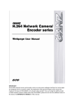
1.3. IP address setting
How to find the IP Address of your device:
The product has its unique IP address, and users can identify the address by converting the
MAC address’ last two sets of hexadecimal numbers described on bottom of the device. Refer
to the following figure and check how to convert a MAC address to an IP address. Type the
identified IP address in the address bar of the Internet Explorer to access the web page of the
product.
12A.07
Ex-Sight.Com
9
Ex-Sight.Com LTD
550012345
550012345
MAC 00:13:23:01:23:45
NVC1000A
P1331010100000-121
MAC 00:13:23:01:23:45
MAC Address
MAC address = 00-13-23-01-23-45 → IP address = 192.168.35.69
Convert the last two sets of hexadecimal numbers to decimal numbers.
12A.07
Ex-Sight.Com
10
Ex-Sight.Com LTD
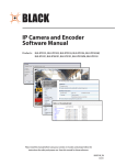
How to change the default IP address:
IPAdminTool software allows users to search and change the IP address of connected devices.
The figure below shows a main UI of the IPAdminTool. The IPAdminTool helps to search
multiple devices. Please refer to the ‘IPAdminTool User’s Mangual.pdf’ for the detailed
information and its usage.
What is IPAdminTool?
IPAdminTool automatically scans all of the products including encoders and cameras on the
network and displays product’s information, including product name, IP address, MAC address,
firmware information, and devices’ uptime. The tool also allows user to change the IP address
or update the firmware. ‘IPAdminTool User’s Manual.pdf ’is available in the SDK (\DOC) folder,
and it is highly recommended for user to review before using this tool for better understanding
of the software functions and administration controls.
Location of IPAdminToo.exe : \BIN\TOOLS\AdminTool
Location of the manual of IPAdminTool : \DOC\
Limitation of the concurrent clients
Depends on streaming configurations and settings, simultaneous connection might reach the
limitation due to system maxed-out capability.
RTSP Streaming, Unicast: Heavily depends on the maximum throughput in a given time.
HTTP Streaming: Heavily depends on the maximum throughput in a given time.
12A.07
Ex-Sight.Com
11
Ex-Sight.Com LTD
2. USING A WEB BROWSER
After the network and power connection are established, access the web browser to view the
live streaming of the connected device. Installation of the ActiveX is required to see the live
page and access full controls in Microsoft® Internet Explorer.
2.1. ActiveX Installation (AxVA.cab)
For full control of a device through a web browser, installation of the ActiveX control is
required. Refer to the following steps to install the ActiveX. Disable the Pop-up blocker or run
“Add-on” notice in a browser to install the ActiveX and Installation file.
Follow the instructions of the dialog boxes and complete the installation. Then the live video is
displayed on the main page of the web browser. You also need to install AxAll.cab.
i
Note
If the ActiveX setup.exe file fails to be installed successfully, close all of the
Internet Explorer windows and go to C:\Program Files\AxInstall folder on your
computer. Then, run Uninstall.exe and try to run the setup.exe file again.
2.2. Recommended PC specification
The following table describes the minimum and recommended requirement of the PC system
to use a Web browser with our products.
12A.07
Ex-Sight.Com
12
Ex-Sight.Com LTD
Item
VGA
OS
Direct X
12A.07
Recommended
D3D support
Microsoft® XP, Vista, and 7
9.0
Ex-Sight.Com
13
Ex-Sight.Com LTD
3. MAIN PAGE CONFIGURATION
3.1. View page
After successfully installing the ActiveX in a web browser, the streaming images from the
device appear on the main view frame in the browser.
If pop-up window appears and asks for user name and password, enter the default value for
the administrator account (case-sensitive) as below:
ID: root
Password: pass
If the image view is not shown,
1. Check if the device is powered on and properly connected.
2. Close all of the Internet Explorer windows and go to C:\Program Files\AxInstall folder on
your computer. Then, run Uninstall.exe and try to run the setup.exe file again.
i
Note
12A.07
If Direct3D Acceleration is disabled, you may not see the view page. In case of the
blue screen appears instead of the proper video, please type ‘dxdiag’ from Start >
Run on your computer and check the DirectX Features.
Ex-Sight.Com
14
Ex-Sight.Com LTD
Display of debugging message on the VIEW page
1. Right-click on the image to display a shortcut menu.
2. Select the Property from the menu.
3. Go to Video > OSD menu.
4. Select the OSD text you want to display by checking the boxes.
12A.07
Ex-Sight.Com
15
Ex-Sight.Com LTD
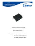
Meaning of each OSD and menu buttons
A
B
C
D
E
F
G
H
I
A. FIRST STREAM / SECOND STREAM : Depends on a model, the device supports up to 4 video
channels. By clicking the drop-down list, users can select the connected channel to display the
streaming image on a view frame. The factory default of the first stream is H.264 with 30 fps.
Go to Setup > Video&Audio > Codec to change the default values.
B. UNICAST-RTSP / MULTICAST - RTSP : A type of data transmission can be selected on this
drop-down menu. Users can select the RTSP stream with either from unicast or multicast.
Go to Setup > System Options > RTSP/RTP to configure the RTSP.
C. Play / Stop : Play or stop the display by clicking this button.
D. FullScreen : Click this menu to extend the image to the full image. Press ESC key to return to
normal image resolution.
12A.07
Ex-Sight.Com
16
Ex-Sight.Com LTD
E. SPK : Select this option to listen to the audio data captured in the camera-installed site.
Before activating the function, ensure that the audio in/out connection of devices are properly
set. For detailed speaker feature configuration, go to Setup > Video&Audio > Audio.
F. MIC : Select this option to send out your voice through the microphone on your PC. To
enable this function, a microphone needs to be connected to the audio input port of PC. For
detailed feature configuration, go to Setup > Video&Audio > Audio.
G. PTZ : Click this button to display the PTZ control menu as the figures below. If the connected
camera type is PTZ, user can control the recording position of the camera by using this menu.
* For a simple control
* For an advanced control
Click and adjust
the pan/tilt
control speed.
Click to expand the menu.
Click and adjust the
zoom control
speed. The zoom
control speed
option is supported
depending on the
protocol.
If you want to use OSD menu, refer to OSD Menu Control Manual.pdf for more details.
H. OSD (On Screen Display) information
It shows the current status of codec. To adjust the setting, go to Setup > Video & Audio >
Codec.
Codec : e.g. H.264 - Selected codec type for the image
frametype : e.g. 720 X 480 - Resolution of the image
1001 - Data size for 1 frame which is calculated by YUY2 format
12A.07
Ex-Sight.Com
17
Ex-Sight.Com LTD
I or P - Frame type shown alternatively of the moment.
dts : e.g. 1234229596.560886 - The stamp showing when the image is encoded on the server.
DTS is short for Device Time Stamp. The timestamp is based on Coordinated Universal Time
(UTC). The start of the time is 00:00:00, Jan 01, 1970.
bitrate : e.g. 562.648 bytes - Bitrate of the image
fps : e.g. 27.000 - Frame per second.
Cache for bound : e.g. 17, 25.040, -4.930
17 : This number indicates that 17 frames are waiting to be decoded on the screen.
25.040 : It shows the current speed of decoding. The normal speed should be 30 ms /fps if
the fps configuration is fixed as 30 fps. In this example, since 17 frames and 27 frames
(currently sensed fps) are waiting to be decoded, the decoding is being processed at 25.040
ms/fps.
-4.930 : This number indicates that the speed to be improved for faster decoding (25.07 =
30ms - 4.930ms)
i
Dts and cache for bound are not manually adjustable.
Note
I. Date and time (Burnt-in Text)
The time and date information are displayed on the image by burnt-in process in the product
server. To prevent intentional time/ data modifications, burnt-in texts generate and embed
into the display before images are compressed and transferred to the client’s PC.
12A.07
Ex-Sight.Com
18
Ex-Sight.Com LTD
4. SETUP CONFIGURATION
To modify settings, click Setup on the main page. The Setup page cannot be accessed without
proper user ID and passwords. Log in to the webpage with the Operator or Administrator
account to change the setting.
Beware of the usage of DSP capacity when configuring the device. High DSP load may
contribute to performance downgrade of the encoder or drop frame rates.. For the best
performance, avoid to consume too high DSP resources for both of 1st stream and 2nd
stream.
Channel(s) in Use
1ch
1ch+2ch
1ch+2ch+3ch
1ch+2ch+3ch+4ch
i
Note
MJPEG
MPEG4
H.264
MD
VCA
Resolution
FPS
Bitrate
D1
D1
25
25
4M
4M
DSP
Usage(%)
39
53
D1
25
3M
65
CIF
25
4M
35
CIF
25
2.5M
40
Remark
Supports full frame
Supports full frame
Supports full frame at D1
with limited bitrate
Supports full frame at CIF
without limitation
Supports full frame at CIF
with limited bitrate
Refer to below for the approximate DSP usage. The figures are estimated
under the condition of D1 resolution, 1.5 Mbps bitrate, and only 1 channel
occupied.
20~25%
around 60~65%
around 75% ~ 80%
3%
20% ~ 25%
To check the DSP load, use the StartEvent tool provided in the SDK.
4.1. LOG IN
To access the Setup page do the following:
12A.07
Ex-Sight.Com
19
Ex-Sight.Com LTD
1. Enter “root” and “pass” (case sensitive) in the User ID and Password. (The root is the
default setting for these fields.)
2. Click the OK button to access to the Setup page.
Apply and Reset
At the bottom of the every configuration page, there are two buttons available:
Apply – Embed customized values to system configurations
Reset – Removes the typed values or settings of current page and returns to the ‘latestapplied’ values.
12A.07
Ex-Sight.Com
20
Ex-Sight.Com LTD
4.2. BASIC CONFIGURATION
4.2.1. User management
Depends on access privilege (group level), the allowed menus may vary one from another.
There are three levels of the user group; Viewer, Operator, and Administrator. The root user
(ID: root, PW: pass) is authorized to all menus on the Setup page and cannot be removed.
Refer to the table below to review group levels and their access privileges.
User Group
Viewer
Operator
Administrator
Accessible Menu
View
View
Setup
Video & Audio
Event Configuration
DI/DO of IO Configuration
VCA
Motion Detect
About
All menus allowed for Operator
Basic Configuration
System Options
UART of IO Configuration
PTZ IO Configuration
Maintenance
Activation
Limitation on user name
A user name can contain from 1 to 14 characters with a combination of alphabet and numbers.
Maximum of 32 accounts are available per an account group.
Character range: All upper or lower case letters and the number from 0 to 9
Limitation on password
A password can contain from 1 to 8 characters with a combination of alphabet and numbers.
Character range: All upper or lower case letters and the number from 0 to 9
12A.07
Ex-Sight.Com
21
Ex-Sight.Com LTD
User Authentication
User authentication setting helps users to configure the streaming image access privileges.
1. Go to Setup > Basic Configuration > Users.
2. Select Enable.
3. Check the option box to allow all anonymous users for accessing the View page. If you
want to request to enter ID and password even for the View page, skip to step 4.
4. Uncheck the option box and click the Apply button to save the changes.
To skip an authentication step before a user logs in to the View and Setup page,
1. Go to Setup > Basic Configuration > Users.
2. Select Disable.
3. Click the Apply button to save the changes.
i
For security purposes, avoid disabling the user authentication.
Note
12A.07
Ex-Sight.Com
22
Ex-Sight.Com LTD
How to add a user
To add a user group for the webpage,
1. Go to Setup > Basic Configuration > Users.
2. Click the Add button below the User List.
3. When the pop-up window appears, type a user name and password.
4. Select the account privilege level; Viewer, Operator, or Administrator.
Refer to 4.2.1 to review the account privileges.
5. Click the OK button to save the changes.
6. Check if the user name is added to the list.
How to modify a user
To change your password or user group,
1. Go to Setup > Basic Configuration > Users.
2. From the List, highlight the user name to change the password or access privileges.
3. Click the Modify button.
4. When the pop-up window appears, type a new password. If you want to change your
user group only, skip to step 6.
5. Re-type the same password in the Confirm password input box.
6. Select the desired user group level.
7. Click the OK button to save the changes.
12A.07
Ex-Sight.Com
23
Ex-Sight.Com LTD
i
Note
12A.07
The user name cannot be modified. If you want to modify the user’s name,
simply remove the account and add a new user.
Ex-Sight.Com
24
Ex-Sight.Com LTD
How to remove a user
To remove a user group name form the User List,
1. Go Setup > Basic Configuration > Users.
2. Select the user name to remove from the User List.
3. Click the Remove button below the User List.
4. When the dialog box appears to confirm your request, click the OK button.
5. Verify if the user name has been removed from the User List.
12A.07
Ex-Sight.Com
25
Ex-Sight.Com LTD
4.2.2. Configuration of HTTP and HTTPS
To set the protocol for the product web server, go the Web Server page by clicking Setup >
Basic Configuration > Web Server.
The default value of web server is set to HTTP. To change its setting from HTTP to HTTPS,
select HTTPS from the menu. It is recommended if enhanced security is required for accessing
the web page. The data transmitted by HTTPS is encrypted by SSL to strengthen the security.
What is SSL?
SSL is the abbreviation of Secure Socket Layer. SSL protects web server and makes it easy for
users to trust the contents. When HTTPS is being utilized to communicate with a server, the
SSL certificate is required for the web server and the certificate enables encryption of video
and audio data during online transactions. OpenSSL is one of the data security protocols for
Linux system, which is used for the product.
Setting the port number of web server
To communicate with server by HTTP or HTTPS with TCP, the port number should be in
between 1 and 65535. The default value is 80.
Redirecting HTTP to HTTPS:
Even when a user tries to access the server with http, it is possible to enable the server to be
redirected to HTTPS. In this case, do not set the value ‘80’ as the port number since it may
cause a conflict with HTTP port.
12A.07
Ex-Sight.Com
26
Ex-Sight.Com LTD
Cache Control
To save the webpage loading time, check the ‘enable content expiration’ checkbox. When it is
enabled, the content-specific pages and images are stored in client cache, and get retrieved for
next 24 hours. Because the content’s expiration time is set to 24 hours, the files in the cache
remains even the mode is turned off at some point. To avoid retrieving the resources from the
cache, manually empty the cache. If the content expiration mode is unchecked, the cache
control is determined by its local PC environment, especially the Internet Explorer option
settings.
12A.07
Ex-Sight.Com
27
Ex-Sight.Com LTD
4.2.3. Setting date and time of system
Click here to
configure NTP
server
Time setting is critical since the log of streaming and burnt-in texts in a video prints the set
time. To configure, go to Setup > Basic Configuration > Data & Time. Every time the setting
has been changed, the web server program of the product will be restarted.
Current server time
It shows the current server-set time.
New server time
12A.07
Ex-Sight.Com
28
Ex-Sight.Com LTD
Select the desired time zone from the drop-down box. If the ‘Automatically adjust for daylight
saving time changes’ checkbox is enabled, then the system will apply the daylight saving time
to respected zone setting automatically.
Time retrieval
Select one of 3 options:
•
•
•
Synchronize the server with your PC time
Synchronize the server with NTP server via internet
Set the server time manually
Time synchronization source
NTP server – Server time is synchronized with NTP server. Users may configure available NTP
servers by following Setup > System Options > NTP section. Up to four NTP servers can be
assigned and the top of the list gets the priority as the default server time.
Real Time Clock on system – Server time is synchronized with Real-time clock that is within the
device. The clock is attached to the board of the product internally and it is recharged
automatically when the server is started.
Interval of synchronization
Everyday 00:00 – The system checks the difference between the system time and time source,
and synchronizes at every midnight
Disabled – Synchronizes only when the encoder is rebooted (factory default)
12A.07
Ex-Sight.Com
29
Ex-Sight.Com LTD
4.3. VIDEO & AUDIO
To change the setting for video input, burnt-in text, audio, and snapshot, go to the Video &
Audio page by selecting Setup > Video & Audio. This menu is configured with five sub menus:
Video-In, Burnt-in Text, Codec, Audio, and SnapShot.
4.3.1. Video input (channel naming/video format/ color control)
i
Note
This section describes about video input setting based on H.264 1channel
encoder. If you are using a different model, move to the chapter 6.REFERENCE TO
MODEL and check the differences.
Video-In from the Video & Audio menu enable users to configure streaming image’s type and
visual attributes. The Video Input Setting page options include:
• Name a channel for the camera
• Select the standard format for video
• Activate deinterlacing algorithm
• Set the image attribute
• Adjust the image position
• Preview the current setting
12A.07
Ex-Sight.Com
30
Ex-Sight.Com LTD
12A.07
Ex-Sight.Com
31
Ex-Sight.Com LTD
Click the Apply button to embed configurations to the system. Click reset button to remove the
typed values or settings of current page and returns to the ‘latest-applied’ values
Friendly Name
Users may provide friendly name (alias) to an individual channel in case when utilizing multiple
channels are necessary. Using alias is recommended to distinguish the device where
environment requires multiple image feedbacks with multiple monitoring devices.
Video Standard Format
For all VA products except VGA CMOS and Megapixel CMOS cameras, NTSC/PAL is
automatically detected. The system detects the video standard format in booting phase. On
the VA encoder products, the manual setting of NTSC/PAL is supported as well by selecting
Disable Auto-Detection. If you change the format and click the Apply button, the loading page
appears while applying the changes. It may take a few tens of seconds to load.
High Performance Image Processing
Selecting ‘Enable Deinterlace Algorithm’ will execute the encoder to merge even fields and odd
fields to display a high performance level image streaming. It is recommended to review the
system capability before utilizing the High Performance Image Processing.
•
•
•
Hardware platform: Processed by the hardware chip of the product board (0% DSP used)
DSP software - best quality: Processed by the software of DSP (approx. 15% DSP used)
DSP software- best performance: Processed by the software of DSP (approx. 5% DSP used)
The factory default is ‘DSP software – Best Performance.’
What is deinterlace?
When an analogue image is transferred to the encoding system of products, it comes with
even fields and odd fields alternately. When the deinterlace option is enabled, two fields are
merged into one frame at the encoder side. It helps the client’s application to reduce
resources required for the deintelacing process.
Setting of image attribute
Brightness, contrast, hue, saturation and sharpness can be modified under this section.
Brightness: The range is from 0 to 255, the default is 128.
Contrast: The range is from 0 to 255, the default is 92.
Hue: The range is from 0 to 255, the default is 128.
Saturation: The range is from 0 to 255, the default is 128.
Sharpness: The range is from 0 to 255, the default is 128.
12A.07
Ex-Sight.Com
32
Ex-Sight.Com LTD
Adjusting the location of image
If the images from camera do not fit into the screen view, users have an option to adjust the
image position vertically or horizontally to fit images into screen.
For PAL, the range of vertical delay is from 2 to 25, and the range of horizontal delay is from 1
to 128. For NTSC, the range of horizontal delay is from 2 to 19, and the range of horizontal
delay is 1 to 128. For pal, the default value for vertical delay is 24 and horizontal delay is 6. For
NTSC, the default value for vertical delay is 16 and horizontal delay is 12.
12A.07
Ex-Sight.Com
33
Ex-Sight.Com LTD
Vertical Delay Min
Vertical Delay Max
Vertical Delay Default
Horizontal Delay Min
Horizontal Delay Max
Horizontal Delay Default
PAL
2
25
24
1
128
6
NTSC
2
19
16
1
128
12
Using PREVIEW button
Preview window appears with current setup visuals. When settings are applied, the preview
window displays the user’s latest modification. The preview window displays respected video
channel (tab) that a user is currently modifying.
12A.07
Ex-Sight.Com
34
Ex-Sight.Com LTD
4.3.2. Inserting Text and Privacy Zone Masking on the image
To change the burnt-in text setting, go to Setup > Video & Audio > Burnt-in Text.
12A.07
Ex-Sight.Com
35
Ex-Sight.Com LTD
Select the stream for
configuration
12A.07
Ex-Sight.Com
36
Ex-Sight.Com LTD
The setting of the Burnt-in Text and Privacy Zone Masking is available for the first stream,
second stream and snapshot separately. To add burnt-in text, privacy zone masking, or burntin image, select the Enable check box after the setting and click the Apply button.
What is Burnt-in Text?
Burnt-in Texts ‘burns’ information into streaming visuals before it gets compressed, thus
prohibiting manipulation or alteration of the events’ time. It allows the file to become reliable
evidence as it discourages intentional manipulation of the date and time for an alibi.
Burnt-in Text Configuration
To display the burnt-in text, check the Enable button on correct video input channel tap
i
Note
For positionings of date, time and text in a visual, it is recommended to use
Normalized X, Y instead of predefined positions (left-top, left-bottom, right-top,
right-bottom). Selecting same predefined positions on all three categories may
cause overlapping texts, depending on image resolution or the position of each
text. Utilizing PREVIEW is highly encouraged to review the selected positions of
those burnt-in texts
Date format
Choose the format of the year, month and day for display.
YYYY-MM-DD / DD-MM-YYYY
Date position
Fix the position to display the date.
Normalized X,Y / left-top / left-bottom / right-top / right-bottom
Date size
Choose character size of date.
Normal/large
Time format
Choose the format of the time for display between “24 HH:MN:SS” and “12 HH:MN:SS”
Time position
Fix the position to display the time.
Normalized X,Y / left-top / left-bottom / right-top / right-bottom
Time size
Choose character size of time between normal and large
Name
12A.07
Ex-Sight.Com
37
Ex-Sight.Com LTD
Type the text to display as a burnt-in text. Maximum of 48 characters with alphabets, numbers,
and symbol are allowed.
Name position
Fix the position to display the name.
Normalized X,Y / left-top / left-bottom / right-top / right-bottom
Name size
Choose character size of time.
Normal/large
Text and Outline Color
Choose the color of the text.
White font with black outline / black font with white outline
Transparency
Choose the transparency from 0 to 75% or custom. (0 to 255. 255 being opaque).
0%, 25%, 50%, 75%
PREVIEW
Preview button allows to view the visual with applied settings (need to press APPLY to view)
Privacy Zone Masking Configuration
Three different zones are available for privacy zone masking. Click the tab of desired zone
number and select the Include Privacy Zone check box to add a privacy zone. All required
settings can be performed basically the same as of the burnt-in text configuration. After
setting the required values, make sure to check the Enable button on the top of the page.
Burnt-in Image Configuration
You can include a company logo image on each stream and snapshot. To include an image,
select the Include Image check box. After configuring the position of the image and its
transparency, select the image file to include by clicking the Browse button and upload it.
The BMP format is allowed only for the image file. The maximum size of the logo guaranteed is
64 x 64 pixels. But, the size can be changed if the image has same area (4096 pixels).
i
Image’s width and height should be multiples of 8.
Note
12A.07
Ex-Sight.Com
38
Ex-Sight.Com LTD
4.3.3. Codec (video codec, resolution, FPS, bit rate control)
To change the codec setting for video streams, go to Setup > Video & Audio > Codec.
Dual stream can
be configured
separately.
Enable codec streaming
Un-checking the box and clicking Apply button will not initiate the streaming videos from the
server.
Naming of each stream
Type any friendly name (alias) to use for the stream. Friendly name helps users distinguish
each stream in multi-channels and streams environment.
Video codec
MJPEG / MPEG4 / H.264. If you change the codec type and click the Apply button, the loading
page appears while applying the changes. It may take a few seconds to load.
12A.07
Ex-Sight.Com
39
Ex-Sight.Com LTD
Image Appearance
Supported resolution
Image Sensor Type of Product
Resolution
CCD sensor
(Max. resolution of
VGA)
NTSC
VGA CMOS
sensor
D1 CMOS
sensor
2MP CMOS 1080p CMOS
sensor
sensor
720x480
720x480
720x480
PAL
D1
720x480
720x576
720x480
(Scaled up
resolution)
VGA
640x480
640x576
640x480
640x480
640x480
640x480
QVGA
320x240
320x288
320x240
320x240
320x240
320x240
4CIF
704x480
704x576
704x480
(Scaled up
resolution)
704x480
704x480
704x480
2CIF*
704x240
704x240
(Developed
704x288
from the scaled
up resolution
704x240
704x240
704x240
CIF
352x240
352x288
352x240
352x240
352x240
352x240
QCIF
176x120
176x144
176x120
176x120
176x120
176x120
XGA
N/A
N/A
N/A
N/A
1024x768
1024x768
HD720
N/A
N/A
N/A
N/A
1280x720
1280x720
SXGA
N/A
N/A
N/A
N/A
1280x1024
1280x1024
UXGA
N/A
N/A
N/A
N/A
1600x1200
N/A
HD1080
N/A
N/A
N/A
N/A
N/A
1920x1080
For more details about the resolution of a megapixel camera, refer to 6.6. IPE1100M.
If you change the resolution and click the Apply button, the loading page appears while
applying the changes. It may take a few seconds to load.
i
When the video input is UXGA or SXGA, the image cannot be resized into 2CIF.
Note
12A.07
Ex-Sight.Com
40
Ex-Sight.Com LTD
Max. FPS
Type the desired frame per second (FPS).
25 fps is a maximum for PAL, whereas 30 fps is for NTSC.
JPEG Quality
This quality value can be set only when the codec is MJPEG. The range is from 0 to 100 and 100
represents the best quality of MJPEG.
GOP Settings
‘P’ Frame count
GOP is an abbreviation of “Group of Pictures” and one GOP has only 1 I frame with other P
frames. Set the number of P frames here and it decides the GOP size. For example, if you have
set the P frame count as 59, then it means that GOP is 60.
Bit Rate Control
VBR (Variable bit rate)
VBR allows a higher bitrate (and therefore more storage space) to be allocated to the more
complex segments of media files while less space is allocated to less complex segments.
Setting the limitation of bitrate will cause the file’s bitrate not go over the limited value. Users
may select values between 128 and 4096 kbits/s.
Unlimited – When the max bitrate is set to unlimited, it has no limitation on bitrate. Its
optimum use is when the devices have enough storage and high quality of image is required.
Q value – You can set the Q value, quantization value for the image quality when the bitrate is
set as variable bit rates.
CBR (Constant bit rate)
You can set the target bitrate from 128 to 8000 and it is recommended when the device has
limited storage capacity.
If you change the bit rate and click the Apply button, the loading page appears while applying
the changes. It may take a few seconds to load.
i
Note
12A.07
Maximum throughput
Considering all of the device usages such as resolution, streaming, and audio
input, the maximum throughput of the encoder is 6 Mbps.
Ex-Sight.Com
41
Ex-Sight.Com LTD
4.3.4. Audio (listening, speaking)
To change the audio setting, go to Setup > Video & Audio > Audio.
Listening to the audio
This page helps you to set the values for capturing the analogue audio generated at the
camera installed site. After the configuration of ‘Listen,’ you can listen to the sound with the
speakers of your PC. To listen to the captured sound, go to the View page and check the SPK
box. If you uncheck the box of ‘Enable capture and compression audio,’ it will disable the
server to capture the sound.
Sampling frequency
You can choose the sampling frequency between 8kHz and 16kHz.
Channel
Only mono type is provided.
Codec
12A.07
Ex-Sight.Com
42
Ex-Sight.Com LTD
You can choose the proper codec from PCM and G.711.
Volume control
The volume is adjustable from 0 to 255. The default is 225.
12A.07
Ex-Sight.Com
43
Ex-Sight.Com LTD
Utilizing speakers
You can set the values for talking to the speakers directly connected to the server of your
devices. To enable this feature you need to connect the microphone with the audio port of
your PC. If you uncheck the box of ‘Enable audio to receiving and playback,’ it disables the ‘Talk
to’ feature.
i
Note
The configuration of codec and frequency of audio output is as same as the
settings of an audio input.
TCP/IP listen port
Set the port for listening to the audio received from the remote. The default is 6000 and the
range is from 1 to 65535. For the details about port numbers used for this products, refer to
TN0301E Ports list for Protocols.pdf.
Volume control
The default is 225 and the range is from 0 to 255.
12A.07
Ex-Sight.Com
44
Ex-Sight.Com LTD
4.3.5. Snapshot
To change the snapshot setting, go to Setup > Video & Audio > SnapShot.
JPEG is the designated format to capture the snapshot and users may select the resolution of
the image along with the image quality.
Using PREVIEW button
The button enables user to review the settings along with image.
How to save the snapshot image?
Click the Preview button and right-click on the captured image and select ‘Save picture as…’ to
save the image in your local PC.
Name
Assign friendly names (alias) for easier identification in multi-channel environments.
Format
Only JPEG format is supported for the snapshot image.
Resolution
User may select the snapshot resolution size. Refer to the table in the Image Appearance
section on Codec (video codec, resolution, FPS, bit rate control).
Quality
You can set the quality of snapshot. The range is from 0 to 100 and the default is 70.
12A.07
Ex-Sight.Com
45
Ex-Sight.Com LTD
i
Snapshot’s latency time is 300~500ms.
Note
12A.07
Ex-Sight.Com
46
Ex-Sight.Com LTD
4.4. EVENT CONFIGURATION
i
Note
This Event setting page is based on 1 channel encoder for H.264. If your camera or
encoder model is different from this model, move to the chapter ‘6.REFERENCE TO
MODEL’ and you can refer to the different part only from this page.
Event Configurations allow users to set up the notification of occurred events. Email, FTP, HTTP,
TCP and Multicast can publish the event message when system detect anomalies or provide
regular updates of any changes occurred in system.
4.4.1. Event Profile
To configure Event Profile, go to Setup > Event Configuration > Event Profile
Configuration
If you tick Enable Old Configuration, the old event configuration, which configured before
update version 1.7.0, applies automatically.
Note: Old configuration can be only changed by CGI commands. For more details, refer to VA
HTTP API Manual.
Add and Modify
12A.07
Ex-Sight.Com
47
Ex-Sight.Com LTD
If you click Add or Modify button, you can enter to configuration page as below. If you
configure First Event, action occurs. But if you configure both First Event and Second Event,
action occurs when both First Event and Second Event are satisfied at the same time.
NOTE: First event has priority than Second event.
Remove
If you click Remove button after choose one on the profile list, the profile deletes.
12A.07
Ex-Sight.Com
48
Ex-Sight.Com LTD
12A.07
Ex-Sight.Com
49
Ex-Sight.Com LTD
Enable Profile
If you want to use event profile, tick Enable Profile and enter name and description.
Providing proper name and description are recommended to inform the specific intent use.
DI/DO
You can configure for each DI / DO and can go to DI/DO configuration page.
Video
Action occurs depending on status.
• Detected: Action occurs when video signal is detected.
• Video loss: Action occurs when video signal is lost.
Motion Detection
Action occurs when configured motion detection occurs to selected zone.
VCA
Before configure VCA Action, you need to configure Setup > VCA page for counter, zone,
configuration and tamper detection. Then count, configuration and tamper can be applied to
each zone
Network
If you tick IP Change, action occurs when IP changes.
Health
•
•
•
•
Temperature: Action occurs when temperature changes.
DSPload: Action occurs when status of DSP usage changes.
System: Action occurs when system, demon status, USB wlan and USB/SD status.
Heartbeat: A signal, which means that device is working normally, occurs depending
on heart interval.
Timer
If you tick Timer and configure Base Time, action starts to occur form Base time and the action
occurs periodically depending on Interval.
12A.07
Ex-Sight.Com
50
Ex-Sight.Com LTD
Action
The event action executes once the event profile is configured. But if you configure both First
Event and Second Event, action occurs when conditions of both First Event and Second Event
are satisfied at the same time. You can choose as an action publisher among DO, Email, FTP,
HTTP, TCP and multicast.
If you click, you can go to
designated configuration
page.
DO
You can choose between DO1 and DO2.
Email
If you choose Email, you can attach a snapshot. For more details, refer to 4.2.2.Email.
12A.07
Ex-Sight.Com
51
Ex-Sight.Com LTD
FTP
You can attach snapshot and text if you want. For more details, refer to 4.2.3.FTP.
• Pre Alarm: When action occurs if you set interval, previous snapshots, which are
stored to storage already, for interval time are sent to FTP. The interval time is limited
to 10 seconds.
• Post Alarm: When action occurs if you set interval, snapshots are sent to FTP during
interval time after action occurs.
HTTP
You can choose HTTP server 1, 2, 3 and 4 as action. For more details, refer to 4.2.4.HTTP.
TCP Event Message
If you tick TCP event message, action occurs . For more details, refer to 4.2.5.TCP.
Multicast Event Message
If you tick Multicast event message, action occurs. For more details, refer to 4.2.6.Multicast.
12A.07
Ex-Sight.Com
52
Ex-Sight.Com LTD
4.4.2. Email
To configure Email, go to Setup > Event Configuration > Email. You can use Email server to get
the event notification from the device and send them to the client application via email. This
page helps you to configure the Email server.
Automatically configured
according to the setting
page of [System Options –
SMTP(email)].
Type the mail receivers,
subject and contents of
email
Below is an example of received email contents when there was a video loss event.
12A.07
Ex-Sight.Com
53
Ex-Sight.Com LTD
4.4.3. FTP
To configure FTP, go to Setup > Event Configuration > FTP. You can use FTP server to get the
event notification from the device and send them to the client application.
Type the IP address, port,
and path to save the files
Type the ID and password of
FTP server so that the device
has the privilege to access to
the FTP server.
Select the file name format
you want.
4.4.4. HTTP
To configure HTTP server, go to Setup > Event Configuration > HTTP. You can use HTTP server
to get the event notification from the device and send them to the client application.
12A.07
Ex-Sight.Com
54
Ex-Sight.Com LTD
Type a message
name to show.
Type IP address
and port of
Type the desired
waiting time from
HTTP server until the
*default: The default
message format is
applied (no parsed
data).
12A.07
Ex-Sight.Com
55
Ex-Sight.Com LTD
4.4.5. TCP
To configure TCP server, go to Setup > Event Configuration > TCP. You can use TCP server to
get the event notification from the device and send them to the client application.
Type a message
name to show on
event message
program
Type the port
number that you
will use for TCP
message. Factory
default is 2555.
4.4.6. Multicast
To configure multicast srver, go to Setup > Event Configuration > Multicast. You can use
Multicast server to get the event notification from the device and send them to the client
application.
Type a message
name to show on
event message
program
Type Address, port,
and TTL according
to your system
setting. Factory
default is 2555.
12A.07
Ex-Sight.Com
56
Ex-Sight.Com LTD
4.5. SYSTEM OPTION
4.5.1. IP Address Filter
For security purposes, the IPAddressFilter allows users to block or grant access to the website
by configuring specific IP addresses. To set an access limits, enable the Enable IP address
filtering option along with Allow admin IP and assign an administrative IP address. Under the
Filtered IP Addresses section, user can list IP addresses and select between Deny or Allow.
IP address setup pop-up window appears when a user clicks Add button. Refer to the examples
provided on this window, and add the desired IP addresses. Click the OK button to see if the IP
addresses successfully appear in the list.
12A.07
Ex-Sight.Com
57
Ex-Sight.Com LTD
To remove an IP address from the list, select the desired address and click the Remove button.
12A.07
Ex-Sight.Com
58
Ex-Sight.Com LTD
4.5.2. Setting TCP/IP (DHCP, Static IP, DNS setting)
To change the TCP/IP setting, go to Setup > System Options > TCP/IP.
IP Address Configuration
IP Configuration by DHCP
If you want to get your IP from DHCP server automatically, check this option and click the
Apply button. You may find the message box of below is popped up. It explains that the DHCP
server in your router device may cause a problem and fail to lease new IP address. In that case,
the latest static IP address will be applied instead. Click OK button to accept the notification.
12A.07
Ex-Sight.Com
59
Ex-Sight.Com LTD
12A.07
Ex-Sight.Com
60
Ex-Sight.Com LTD
Use the static IP address
If you want to use your device with the static IP, enable the ‘Manual IP configuration’ and click
the Apply button.
IP address: The IP address of your device
Subnet mask: The address of subnet mask of your device.
Gateway address: The gateway address of your device.
Broadcast address: It is automatically fixed by the subnet mask and IP address of your own.
For example, if you use B class (255.255.0.0) of mask, the broadcast address will be
192.168.255.255.
The test button shows if the typed IP address is occupied or not. You may find the popup
windows as below according to the availability of typed IP address.
Occupied IP
Available IP
DNS Configuration
Type the IP address of DNS server you use. The test button for checking the IP address
availability is also supported for DNS configuration.
12A.07
Ex-Sight.Com
61
Ex-Sight.Com LTD
4.5.3. NAT setting (Port mapping)
To change the NAT setting, go to Setup > System Options > NAT.
If RTSP connection via public IP address checkbox is enabled, then the IP address or domain
name will be automatically retrieved from the URL tab of the device web page. In order to see
the device’s webpage and streaming on the web page, both HTTP port and RTSP port should
be forwarded.
Suppose you set the IP address of the router to 112.216.89.172 and forward the HTTP port to
8080 and RTSP port to 22230. Then, the port forward setting is:
1. Check the box of ‘Check this box to enable RTSP connections on a different port when the
unit is accessed via its public (NAT) IP address.’
2. Type the RTSP port number that your router knows. Check the RTSP port number stated in
System Options > RTSP/RTP.
3. Click the Apply button to implement the setting.
When you use domain name, you should check out if the DNS or DDNS is enabled.
Go to System Option > TCP/IP for DNS setting.
Go to System Option > DDNS for DDNS setting.
If you want to access the webpage you should use the IP address of the router plus the port
number. (http://112.216.89.172:8080) If you do not configure the RTSP port forwarding
properly you will see the error message.
i
Note
12A.07
Prior to the NAT setting, the port forwarding of router should be completed
manually. System does not provide an automatic NAT traversal service.
Ex-Sight.Com
62
Ex-Sight.Com LTD
4.5.4. Setting NTP server
To change the NTP service setting, go to Setup > System Options > NTP.
http://mail2.naver.com/list/?folder=0
NTP Server Lists
You can set up to 4 NTP servers as you can see at the example of above. To enable the NTP
servers, DNS server setting should be done in advance in the menu of TCP/IP page and please
check out if the DNS configuration is accurate.
I am SNTP Server
It is also called ‘Squid server.’ When you have multiple servers for the device, it helps to reduce
the network load because only the one with ‘I am SNTP Server’ checked will get the time
information from the NTP servers and other servers for the device are synchronized with this
Squid server.
How to use:
1. Enable ‘I am SNTP server’ of squid server and click Apply.
2. Access the webpage of the device which is supposed to be the client device of the
squid server. Go to System Options > NTP and type the IP address of squid server on
the ‘NTP Server 1s’t. (Format example : 192.168.11.4)
3. Click ‘Test’ button to find out if it works fine.
i
It will take about 3~4 minutes until the squid server response.
Note
12A.07
Ex-Sight.Com
63
Ex-Sight.Com LTD
4. Go to Setup > Basic Configuration > Date & Time and choose the ‘Synchronize with
NTP server’ for the method of New Server Time menu. Make sure if the ‘NTP Server’
displays the designated squid server’s IP correctly with red characters.
5. Click ‘Apply’ button and it will be restarted.
12A.07
Ex-Sight.Com
64
Ex-Sight.Com LTD
4.5.5. Setting property for UPnP
To change the Universal Plug & Play configuration, go to Setup > System Options > UPnP.
UPnP allows IP devices to connect seamlessly, and to simplify the implementation of networks
in remote PC environments.
To view the device property, click START on Windows OS and type “Network”, which displays
all the devices on the network. Find the device, right-click the mouse and select [property].
e.g. Customized UPnP name and description
Friendly name
Manufacturer name
Model name
Model description
Configuration
To allow PC to search the device, check the box of ‘Enable UPnP.’
12A.07
Ex-Sight.Com
65
Ex-Sight.Com LTD
Friendly Name: Type any friendly name to be displayed on the UPnP property window.
Manufacturer Description
Type manufacturer’s name and URL, which will be displayed in UPnP property window.
Model Description
Type the model name, description, and associated URL which will be displayed in UPnP
property window.
12A.07
Ex-Sight.Com
66
Ex-Sight.Com LTD
4.5.6. USB/SD Storage
i
Note
This USB/SD setting page is based on 1 channel encoder for H.264. If your camera or
encoder model is other than this model, this page may not be seen according to
your model. Refer to the chapter 6. REFERENCE TO MODEL.
Mounted devices are shown by
clicking ‘Refresh’ button
Detail device
information by
selecting one of
items on the storage
list
For more stable usage of your
USB device, format the device
first before using it.
Storage device Information is
displayed by clicking the
‘Select Record Device’ button
Click Apply button to use
selected device.
This page is provided to search mounted USB/SD storages device and select one of them for
data recording. Please follow the steps described at the below. After setting this page, move
to the menu of System Options > AVI File Recorder page and start the recording.
12A.07
Ex-Sight.Com
67
Ex-Sight.Com LTD
How to set the recording device
1. Insert a USB or SD memory card.
2. Click the ‘Refresh USB/SD Device List’ and you can find that the devices are listed on
the window. If the storage device is not listed right after mounting, wait for a few
seconds and click the Refresh button again as it might take some time until the device
is recognized.
3. Select and the device on the list and then the device information such as name, type,
total capacity, free space and status are shown on the right side of the list.
4. Click the ‘Select Record Device’ button and the chosen device information is listed on
the Record Device Control.
5. Click Apply button to use the selected device for recording.
6. If you have completed the steps above, go to the System Options > AVI File Recorder
menu and you can start the recording.
i
Note
If the total capacity and free space are not shown, refresh the device list in a few
seconds. Because it takes some time to bring the file system information to the
web page. If the space information is not shown still, your storage device is not
formatted properly. Format your storage device and try to refresh again.
Formatting the disk
For more stable usage of your USB device, you need to format the device prior to using it.
Select the storage device you want to format and choose whether you want vfat format or
ext3 format. Click the desired format type, and then click the Apply button.
Ejecting the disk
When you want to remove the storage device safely, click the ‘Eject’ button. If the ejecting
process is done, now you can remove the memory stick from your device.
12A.07
Ex-Sight.Com
68
Ex-Sight.Com LTD
4.5.7. USB Wireless LAN
i
Note
This USB Wireless setting page is based on 1 channel encoder for H.264. If your
camera or encoder model is other than this model, this page may not be seen
according to your model. Refer to the chapter 6. REFERENCE TO MODELS.
After the wireless LAN configuration, you can use the device in one of two modes: wired LAN
or wireless LAN. You cannot use the camera in both modes simultaneously. To switch between
wired and wireless modes, you have to plug or unplug the Ethernet cable. Unplugging the
Ethernet cable switches the device to wireless mode automatically. For the USB Wireless LAN
setting, go to Setup > System Options > USB Wireless LAN.
12A.07
Ex-Sight.Com
69
Ex-Sight.Com LTD
Successful connection
Available networks list is
shown by clicking the
‘Refresh Network List’
button
Retrieved network device
settings values are shown
by clicking the ‘Copy to
user Setting ‘button
Type the network key
value of selected AP.
Connected network
status is shown by
‘Update Status’ button
i
Note
12A.07
For some of APs, it may fail to get the DNS information when a user tries to connect
WLAN.
Ex-Sight.Com
70
Ex-Sight.Com LTD
If you are ready with the USB wireless LAN device, follow the steps below.
Step 1. Recognizing the USB wireless LAN device
1. Insert the USB wireless LAN device into the encoder or IP camera.
2. After a few seconds, click the ‘Refresh Network List’ and you can see that the device is
listed on the window.
3. Click the device you want on the list. Then, the device information such as ESSID, mode,
MAC address, channel, and encryption are shown on the right side of the list window.
4. Click the ‘Copy to user setting’ button and the chosen device information is copied on
‘Networks to connect’ section of below.
If ‘Not connect wireless….’ message is displayed after clicking the ‘Refresh Network
List,’ please check the setting of your wireless AP/router. Also make sure the USB
wireless LAN card is mounted on the unit properly.
i
Note
Step2. Connecting wireless network
If you have completed the recognition of the USB device for wireless LAN at the step1, you can
find that the ‘Network name, Mode, Authentication, and Encryption’ are filled automatically
according to the wireless LAN device information.
1. Type the ‘Network key’ and confirm it. The network key should be equal to the AP or
client PC you will communicate.
2. Set the Time out and Retry count referring to the explanation of below.
Time out - When there’s no answer from the server for time out seconds, it means it
failed connecting to the server and you need to try to connect again.
Retry count – The number of retrial connections when there’s no answer from the
server.
i
Note
The current time out or retry count is not renewed automatically. Try to renew the
page manually to see if the network is connected properly.
3. Set the wireless network IP configuration. If your mode is Ad-Hoc, only static IP setting
is allowed.
12A.07
Ex-Sight.Com
71
Ex-Sight.Com LTD
IP configuration by DHCP - Get the IP address from DHCP automatically.
Manual IP configuration – Get the IP address with the manual setting. If your mode is
infrastructure (AP) networks, you should check out the range of IP address.
4. If you have completed the configuration of above, you can save or try to connect the
wireless LAN with button of Apply and Reset.
Apply – Save the current setting and apply them.
Reset – It does not save the setting of the current page and go back to the prior setting.
5. Disconnect the Ethernet cable from the device. Unplugging the Ethernet cable switch
the device to wireless mode automatically.
6. Wait about 30~40 seconds to switch the wireless mode.
i
Note
i
Note
i
Note
12A.07
Switching time between wired and wireless modes may take longer than expected
according to the network connections.
When rebooting the device with wireless mode, the device’s boot time may be
increased to 4~5 minutes due to the failure of NTP time synchronization.
If the wireless LAN is not connected successfully, make sure the USB wireless LAN
card is mounted on the unit properly. Click ‘Refresh Network List’ button and try to
search network devices again. Please check out the step1 and step2 again.
Ex-Sight.Com
72
Ex-Sight.Com LTD
4.5.8. RTSP/RTP (multicast or unicast)
For the RTSP/RTP setting, go to Setup > System Options > RTSP/RTP.
12A.07
Ex-Sight.Com
73
Ex-Sight.Com LTD
Can be configured
separately by clicking
on the name, multicast
or unicast
12A.07
Ex-Sight.Com
74
Ex-Sight.Com LTD
The products (encoders and IP cameras for H.264) support the multicast and unicast streaming
for both of 1st stream and 2nd stream. Click the tab of MULTICAST and UNICAST as the picture
above shows and configure the RTP session as required by your network system.
RTSP Configuration
To start the data streaming such as video, audio or metadata from the product server, tick the
box of Enable RTSP Server. If you remove the check in the box, the streaming stops from server
and the real time view is disabled on the web page.
Below is the requesting format of URL and Port for RTSP streaming. Each of IP address, port,
and session name are open to be typed by user.
rtsp:// rtsp server ipaddress : port / rtp session name
port : 554
e.g. rtsp://192.168.111.32:554/ch0_unicast_firststream
NAL unit option
The product supports both of NAL stream and Byte stream. The factory default setting is the
Byte stream which includes NAL unit header. To change this setting to the NAL stream, check
this check box.
•
•
NAL Stream: The stream consists of only NAL units
Byte Stream: The sequence identifier, NAL header, is included between NAL streams
The data structure of byte stream
I SPS
I PPS
I IDR
I P SLC
I P SLC
……
I IDR
I P SLC
……
I : Sequence Identifier
SPS : Sequence Parameter Set
PPS : Picture Parameter Set
IDR : IDR Slice
P SLC : P slice
You can refer to the ‘VA Media Data Manual’ in the SDK for more information about the video
format of the product.
12A.07
Ex-Sight.Com
75
Ex-Sight.Com LTD
12A.07
Ex-Sight.Com
76
Ex-Sight.Com LTD
RTSP Authentication
If you want to use the authentication process for getting the RTSP streaming from the product,
you can choose one of the options.
Authentication type
Basic: It uses simple way of encryption of ID and PW with clear text
Digest: It uses more enhanced way of encryption.
Please refer to the http://www.faqs.org/rfcs/rfc2617.html for more information about the
authentication of clients using basic and digest.
Privilege
You can use one of the user groups for RTSP Authentication.
RTSP configuration for MULTICAST
i
Note
If you have decided the communication way between multicast and unicast, the
option is applied to both of first stream and second stream on the web page. But,
each of the 1st stream and 2nd stream can be configured with different way by HTTP
API. Refer to the VA HTTP API manual.pdf in the SDK.
IP Address
In order to get the streaming data from the device, you should set the IP address of group
which is used for PC to join. ‘0,0,0,0’ is configured as a factory default and it enables router
program to generate the available IP for the device automatically. If you want to use any
specific address, type the address in the blank.
i
Note
UDP/RTP multicast is not allowed for streaming even if the address and the port
information are known.
How auto configuration of IP address works?
As the session name for each RTP session is defined already on the server, your PC can get the
stream by the ‘rtsp:// rtsp server ipaddress : port / rtp session name’ without the manual
decision of IP address on the webpage.
Port
12A.07
Ex-Sight.Com
77
Ex-Sight.Com LTD
Set the port number used for router to receive the streaming data from the product (No need
for unicast). ‘18888’ is set for video data of 1st stream and ‘28888’ is for video data of 2nd
stream. Refer to the ‘Ports list for the product connection’ at the end of this section 4.5.7.
TTL
Set the TTL value. If you set 1 for TTL, it means the packet will pass only in a subnet (No need
for unicast).
12A.07
Ex-Sight.Com
78
Ex-Sight.Com LTD
What is TTL?
It’s the abbreviation of Time to live. If data is sent out from the encoder via network and all
of the packets are alive permanently on the network, it will cause the big network load. TTL
helps to reduce the network load by controlling the time of staying on network. For
example, if you set the TTL as 50, the data will be deleted after passing by 50 routers.
Packet Size
Select the packet size you want. You should consider the proper packet size according to your
network bandwidth. If your network allows you enough bandwidth for the product connection,
you can set higher size. The factory default is 1500 bytes.
Session name
Type the session name. The allowed ranges for the session name are 64 characters with
alphabets, Arabic numbers, and underscore (_).
Session information
Type the session information you want to display.
Session Description
Type the session description for more detailed information.
Include audio stream
Check this box if you want to include the audio stream as well as video stream. For your
information, video stream is the fundamental stream whenever you request the RTSP stream
as a factory default.
Include meta data
Meta data contains the motion detection and VCA (video contents analysis) data. Check this
box if you want to include the meta stream as well as video stream. For your information,
video stream is the fundamental stream whenever you request the RTSP stream as a factory
default.
i
Note
Refer to the ‘VA Media Data manual.pdf’ for analyzing the stream of video, audio or
meta data.
Enable QoS
By enabling the Quality of Service (QoS) feature, you can specify priority level of network
traffic for video, audio, and metadata (motion detection and VCA). For each traffic type,
determine the DSCP (Differentiated Services Codepoint) value, which represents a QoS class in
12A.07
Ex-Sight.Com
79
Ex-Sight.Com LTD
the Differentiated Services (DiffServe) model. For the details about the DiffServ standard, refer
to RFC2474 and RFC2475.
RTSP Configuration for UNICAST
It is same as the configuration of multicast stream except for the items below.
Only for multicast system: IP Address, Port, and TTL
12A.07
Ex-Sight.Com
80
Ex-Sight.Com LTD
Ports list for the product connection
Refer to the document TN0301E Ports list for protocol.pdf for detailed information about port
number. It is found in the SDK (\DOC)
12A.07
Ex-Sight.Com
81
Ex-Sight.Com LTD
4.5.9. Setting property for mDNS (Multicast DNS)
For the multicast DNS setting, go to Setup > System Options > mDNS.
If you have your own program or device which is required to use the mDNS, this page helps
you to customize the name of model and manufacturer instead of factory default.
Configuration
If ‘Enable’ checkbox is checked, mDNS is activated. Type the Friendly Name (alias) to be shown
on the application program.
Manufacturer Description
Type the manufacturer company’s name and provide URL.
Model Description
To give brief description about the model, name, description and URL boxes are available for
users to input.
12A.07
Ex-Sight.Com
82
Ex-Sight.Com LTD
4.5.10. Setting SMTP
To change the SMTP setting, go to Setup > System Options > SMTP(email).
You can set the user’s mail account and server to apply this SMTP for event or any other SMTP
required purpose.
Configuring user information
Unit Name
Type the friendly name (alias) for the product server to show on e-mail and it helps you to
distinguish the devices from other devices when you use multiple network video servers.
Input range: 40 characters limit
From email address
Type the e-mail address of a sender.
Input range: 128 characters limit
Configuring server information
Mail server
12A.07
Ex-Sight.Com
83
Ex-Sight.Com LTD
In order to send the e-mail message, the product needs the information of user’s mail server.
Type the Mail server with the host name or IP Address. If you use the host name, it requires
the DNS registration in advance. Check the DNS setting on System Options > TCP/IP tab.
Input range: 128 characters limit
Mail server port
Type the mail server’s port number with the range from 0 to 65535.
i
Note
If your email server requires encryption process of SSL and TLS, select the ‘Enable
encrypted connection (SSL)’ check box. TLS (Transport Layer Security) and SSL
(Secure Sockets Layer) algorithm can be required for the security of communication
over networks. It depends on your email server and you should check out the
communication protocol of SMTP server.
Logon Information
User name
Input range: 128 characters limit
Password
Input range: 32 characters limit
8 asterisks cannot be used for the password.
Test with current configuration
You can check out in advance if the e-mail account is available or not with the ‘test’ button.
Type the e-mail address and click the test button. If you have seen the message below, you
should set the DNS first at System Option > TCP/IP menu.
If you have seen the message below, the entered mail account is valid.
12A.07
Ex-Sight.Com
84
Ex-Sight.Com LTD
Client configuration
VA only supports ESMTP.
Certification method
Three methods are supported. (Order of priority 2,3>1)
1. Anonymous Access
2. Basic authentication ( SSL optional) (AUTH LOGIN)
3. Basic authentication ( SSL optional) (AUTH PLAIN)
12A.07
Ex-Sight.Com
85
Ex-Sight.Com LTD
4.5.11. Recording & Playback with USB/SD storage
To change the AVI File Recorder setting, go to Setup > System Options > AVI File Recorder.
Steps for manual recording
Step 1. Selecting a recording option
12A.07
Ex-Sight.Com
86
Ex-Sight.Com LTD
If you want to record the data, the box of Enable Recorder must be checked. Otherwise, the
data will not be recorded even if you click the START button for Instant recording.
To automatically start recording as soon as the storage device is mounted, select Enable
automatic recording shortly after mounting storage device. With this menu selected, you
can record the data according to the recording segmentation rule. For more details about
the segmentation rule, go to Step 5.
Step 2. Selecting a recording storage
You can choose one of the recording storage devices, SD card or USB memory stick.
Step 3. Recycling options
You can choose one of the options when the storage is full of data
• Stop recording: Stops recording and keep the recoded data.
• Delete files and recycle (oldest first): Replace old files with newly created files.
Step 4. File name convention
Type the file name that ends with _YYYYMMDD_hhmmss.avi. For easier recognition of
duplicate files, the end of every recording file name includes the date and time information
as a default.
Step 5. Segmentation of files
• Check the ‘Do not segment’ if you want to create the recording data as one file.
• Segmentation by file size: Type the size of file. The range of the file size is from 1 to
1440 Megabyte(s).
• Segmentation by time base: Type the minutes to segment. The range of the file size is
from 1 to 60 minute(s).
Step 6. Selecting stream source for primary option
You can choose primary recording source from either 1st stream or 2nd stream. It’s not
allowed to record both of them at the same time. If you check ‘None,’ the encoder of IP
camera does not record neither of 1st stream nor 2nd stream.
Option. Recording secondary stream (snapshot stream)
Do not want to record the snapshot stream?
12A.07
Ex-Sight.Com
87
Ex-Sight.Com LTD
Select None at the end of stream source options.
Selecting the stream source for recording
Secondary recording is prepared for the users who want to record the stream of snapshot.
This is operated separately from the primary recording and you can get the continuous shot
with JPEG format. Set the resolution, quality and fps of the recoding image.
Customizing the resolution
If you choose CUSTOM as the value of the resolution, you’re able to set the image size as
you want regardless of the fixed standard size. Type the pixels in the fields of width and
height.
If you have finished the setting above, click the Apply button to save and apply the setting. To
manually start or stop the recording, click the START and STOP button for Instant recording.
This button activates instant recording without depending on the recording setting rules.
Steps for VCA event recording
To record VCA event data only, unselect Enable automatic recording shortly after mounting
storage device, and then select Enable automatic recording with VCA event triggering. In this
case, you do not need to set the segmentation rule. All of configuration is the same as manual
recording but optionally, you need to set up ‘Event Recording’ tab.
Step 1. Set the time of post-alarm recording. Then, when VCA event is triggered, the images
will be recorded for the configured time only.
Step 2. Check the box of ‘Enable automatic recording with VCA event triggering’ to enable the
VCA event recording. If the desired stream source is selected from Primary/Secondary
recording setting section, the VCA event data will be automatically recorded upon the event
triggering. Go to Step 6 or Option on Steps for manual recording for more details about
selecting the stream source.
Step 3. Click the Apply button to save the changes.
12A.07
Ex-Sight.Com
88
Ex-Sight.Com LTD
How to play back the recoding files on the webpage
1. Click the LIST button at the bottom of the page.
2. Then, you can see the new window is opened as below. The created directories are listed on
the web page.
3. Click one of the directories you want. Then, you can see the recording files are listed.
12A.07
Ex-Sight.Com
89
Ex-Sight.Com LTD
i
Note
12A.07
If the file name is not created as the file name convention, format the storage
device to FAT32, with the default allocation size, on Windows. And use the
formatted device on the product for recording again.
Ex-Sight.Com
90
Ex-Sight.Com LTD
4. Click the file you want to open. Then, the download window appears as below. You can
open or save the file on your local disk
How to download the recording file via FTP
1. Check if the FTP server is enabled from System Options > FTP.
2. Log in to the FTP server by entering the user name and password (ID: root, PW: pass).
3. Follow the steps from 2 to 4 on How to play back the recoding files on the webpage.
12A.07
Ex-Sight.Com
91
Ex-Sight.Com LTD
4.5.12. LED Setting
i
Note
This LED setting page is based on 1 channel encoder for H.264 and this page can be
different according to your product model type. Refer to the chapter 6. REFERENCE
TO MODELS.
To change the LED setting, go to Setup > System Options > LED.
You can customize the LED operation according to your system requirement. Please refer to
the example scenario first.
Example of configuration
Scenario:
“When the video signal loss is detected, let top LED blink for every 5 seconds”
Setting:
LED1 - Ticked
Event Publisher - vsignal
12A.07
Ex-Sight.Com
92
Ex-Sight.Com LTD
Operation - Blink
Time Out – 5
Option – Turn on the LED of vsignal : Select ‘When video signal loss is detected.’
12A.07
Ex-Sight.Com
93
Ex-Sight.Com LTD
Basic configuration
1.
2.
3.
Select the ‘Event Publisher’ you want to apply for the LED1 / LED2.
Select the ‘Operation Type’ for each LED; Blink or On mode.
Select the ‘Time Out,’ among 1 ~ 5 sec or permanent alarming.
Location of LED
LED locations may differ depends on the device model. Check the hardware manual for correct
location of the parts.
Are you configuring DSP load, temperate, and video signal loss?
The option section provides the configuration of DSP load, temperature change, and video loss.
(1) Set the dspload limits to
E.g. Setting the value as 90% - While the DSP load keeps lower than 90%, the LED will operate
as you configured at Location tab.
(2) Set the temperature limits to
E.g. Setting the min 0 and max 65 - While the temperature is between 0 and 65, the LED will
operate as you configured at Location tab.
(3) Turn on the LED of Vsignal
Select one of the options between ‘When video signal loss is detected’ and ‘When video signal
is normal.’ Then, the selected LED will operate when the selected condition is satisfied.
(4) Turn on the LED of Heartbeat
Select one of the options between ‘When heartbeat status is watchdog’ and ‘When heartbeat
status is normal.’ Then, the selected LED will operate when the selected condition is satisfied.
i
Note
12A.07
For more details about the publisher’s triggers condition, refer to the ‘Event System
Manual.pdf’ in the SDK. It describes the threshold for event triggering, event
message format, and triggering condition etc.
Ex-Sight.Com
94
Ex-Sight.Com LTD
4.5.13. DDNS (Dynamic DNS)
To change the Dynamic DNS setting, go to Setup > System Options > DDNS.
1. Check the ‘Enable DDNS’ box.
2. Select the protocol type you want.
i
For DDNS Protocol types, DynDNS and CUSTOM07 types are available.
Note
3. Type the domain name you want to use for the product.
4. Type the update time. The factory default is 600 seconds and it enables the product notify
the DDNS of the current domain name.
5. Type the user name and password of your DDNS account.
6. Click the Apply button.
An invalid DDNS setting may display an error message saying: “Failed to configure a DDNS.
Check out if you account is valid.” Check the following error codes after the error message, and
see if you need to change the setting.
Error Code
Cause of the Error
0x48
- The Logon Information (user name and password) is incorrect.
- The domain name for the DDNS Setting has not been input or incorrect.
0x12 or 0x00
The DNS Configuration from the TCP/IP menu needs to be completed.
12A.07
Ex-Sight.Com
95
Ex-Sight.Com LTD
Logon Information
8 asterisks cannot be used for the password.
12A.07
Ex-Sight.Com
96
Ex-Sight.Com LTD
4.5.14. FTP
To enable FTP server for accessing USB SD memory, go to Setup > System Options> FTP. You
can download .AVI files via FTP server. The authorized user is the one who has the ‘ROOT’
authorization. The account user name and password is the same as those of TELNET/web user.
12A.07
Ex-Sight.Com
97
Ex-Sight.Com LTD
4.5.15. Snapshot Recorder
To record snapshot images in JPEG format on a storage device, go to Setup > System Options >
Snapshot Recorder.
If you click, you can go to
snapshot settings page.
Steps for manual recording
Step 1. Selecting a recording option
12A.07
Ex-Sight.Com
98
Ex-Sight.Com LTD
If you want to record the data, the box of Enable Recorder must be checked. Otherwise, the
data will not be recorded even if you click the START button for Instant recording.
To automatically start recording as soon as the storage device is mounted, select Enable
automatic recording shortly after mounting storage device. With this menu selected, you
can record the data according to the recording schedule setting without clicking the START
button for Instant recording.
12A.07
Ex-Sight.Com
99
Ex-Sight.Com LTD
Step 2. Selecting a recording storage
You can choose one of the recording storage devices, SD card, USB memory, NAS, or FTP. In
case of selecting NAS or FTP, the server and login information must be set. Click on NAS or
FTP to display a setting window. For NAS, refer to the Network-attached Storage (NAS)
Setup section for configuring path and logins.
Step 3. Recycling options
You can choose one of the recycling options when the storage is full of data.
• Stop recording: Stops recording and keep the recoded data.
• Delete files and recycle (oldest first): Replace old files with newly created files. If you
use FTP for a storage device, this option will not be available.
Step 4. File name convention
Type the file name that is composed as {HOST} _{PREFIX}_ch#_YYYYMMDD_hhmmss.jpg.
For easier recognition of duplicate files, the end of every recording file name includes the
date and time information as a default. In case of using FTP for the storage option, the
feature to overwrite files with the same file name is supported.
Step 5. Time for recording
The recording time can be scheduled with three different sections in 00:00~24:00 (hh:mm).
Step 6. Stream source setting
If you click “snapshot”, you can go to snapshot settings page. The time interval supported is
from 500ms to minute. If you input 500 for the interval, you may get 1 shot of image
recorded for every 500ms.
If you have finished the setting above, click the Apply button to save and apply the setting. To
manually start or stop the recording, click the START and STOP button for Instant recording.
This button activates instant recording without depending on the recording setting rules.
Steps for VCA event recording
To record VCA event data only, unselect Enable automatic recording shortly after mounting
storage device, and then select Enable automatic recording with VCA event triggering. In this
mode, event data will be recording regardless of the recording schedule setting. All of
configuration is the same as manual recording but optionally, you need set up ‘Event
Recording’ tab.
12A.07
Ex-Sight.Com
100
Ex-Sight.Com LTD
Step 1. Set the time of post-alarm recording. Then, when VCA event is triggered, the images
will be recorded for the configured time only.
Step 2. Check the box of ‘Enable automatic recording with VCA event triggering’ to enable the
VCA event recording.
Step3. Click the Apply button to save the changes.
12A.07
Ex-Sight.Com
101
Ex-Sight.Com LTD
How to check recoded JPEG images
1. Click the LIST button at the bottom of the page.
2. Then, you can see the new window is displayed as below. The created directories are listed
on the web page.
3. Go to ‘Index of/download/mnt/mmcblk0/snapshot/’ directory where the snapshot files are
located. The sub folders will be created in the order of year-month-day > hour > minute. In the
example below, you can see that the folder includes the snapshot files that were created at
17:27 on 2010-11-19.
4. Check the file created time with the folder name and select the desired folder. Then, click
the desired file you want to open.
12A.07
Ex-Sight.Com
102
Ex-Sight.Com LTD
Network-attached Storage Setup
①
②
③
④
① NAS Server: IP Address of NAS
② Target Path: Directory folder inside NAS
③ User Name: NAS-attached computer’s login User Name
④ Password: NAS-attached computer User Name’s associated password
i
Note
i
Note
When setting the Target Path under the Server Information, only the parent
directory will be allowed. Designating any child directory under the parent directory
will not work.
Password box only displays up to first 8 characters of the passwords when the
menu is opened again after save. This doesn’t impact the actual length of password.
How to download the recording file via FTP
1. Check if the FTP server is enabled from System Options > FTP.
2. Log in to the FTP server by entering the user name and password (ID: root, PW: pass).
12A.07
Ex-Sight.Com
103
Ex-Sight.Com LTD
3. Follow the steps from 2 to 4 on How to play back the recoding files on the webpage.
12A.07
Ex-Sight.Com
104
Ex-Sight.Com LTD
4.5.16. SNMP
To enable the remote management of IP devices, go to Setup > System Options > SNMP. The
Simple Network Management Protocol (SNMP) is to monitor network-attached devices for
conditions that warrant administrative attention. By retrieving the system information, it
allows to manage network architecture, performance, device, and security. To enable SNMP,
select the Enable check box. The encoder supports SNMP version 1 and 2.
SNMP information
Input your SNMP information on the following section. For the Read Community, input the
community name, which is the authorized ID for reading SNMP data. The factory default value
is ‘public.’
Trap setting
The Trap can be considered as sending an event message from an event publisher such as DIO
and VCA. Choose the SNMP Trap version to receive Trap event, and input the IP address and
community on the text box.
i
Note
For the details about SNMP MIB information, please contact our support team.
(MIB file: \BIN\LIB)
4.5.17. VSaaS
12A.07
Ex-Sight.Com
105
Ex-Sight.Com LTD
To configure the VSaaS server connection, go to Setup > System Options > VSaaS. You can use
this page if you have VSaaS
server .
VSaaS setting
1. When you enable VSaaS setting, you should type server address, TCP pot of VSaaS
server and update interval.
2. When connect to VSaaS server, VA requests MAC address, brand and model name to
VSaaS server.
3. VA connect to VSaaS server periodically depending on Update Interval and update
12A.07
Ex-Sight.Com
106
Ex-Sight.Com LTD
4.6. IO CONFIGURATION
To set up DI/DO and UART, go to Setup > IO Configuration. This menu is configured with two
sub menus: DI/DO and UART.
4.6.1. DI/DO control
i
Note
This DI/DO setting page is based on 1 channel encoder for H.264. If your camera or
encoder model is other than this mode, move to the chapter ‘6.REFERENCE TO
MODEL’ to check the difference between models.
If you should install the additional device such as alarm system or sensor system, you can
configure the DI (Digital Input) and DO (Digital Out) in this page.
DI Resource Type
You can choose the DI resource type, RELAY or VOLTAGE (The maximum is 5V).
12A.07
Ex-Sight.Com
107
Ex-Sight.Com LTD
DI & DO Status
It reflects the current states of actual DI and DO. In case of the 1 channel encoder for H.264, 2
of DI and DO are supported for each. Refer to your product model specification for supported
number of DI and DO.
Scenario Example
When it’s assumed that DI#1 and DO#1 are coupled by event system. The DI#1 trigger type is
Normal Open. Suddenly DI#1 is triggered by any kind of event.
Expected Response – The status of DO#1 will be changed from OFF to ON, if the default setting
is OFF. The status of DI#1 will be changed from OPEN to CLOSE.
DO Control
If you want to test DO operation manually on the webpage, click the OFF or ON button. Then,
you can see that how DO works. These commands also affect the ‘DO status’ because the ‘DO
status’ shows the current status of DO.
Friendly Name
You can type any friendly name for DI and DO. This setting helps you to identify which DI or DO
is activated especially when you have multiple product servers on your application program.
DI Trigger Type
You can select the trigger type between normal open (NO) and normal close (NC).
DI Re-arm Period
Use this option to set up detection time interval for event publishers. For example, if you input
‘0,’ it generates events all the time whenever DI is detected. But if you input ’10,’ only 1 event
will be triggered for 10 seconds even if multiple DIs are detected for this 10 seconds.
DO Hold period
The DO Hold Period indicates for how long does the DO works. For example, if you input ‘0,’ a
DO device keeps working until a user turns it off manually. If you input ’10,’ a DO device will
work for 10 seconds and finish the operation. However, if you turn a DO device on manually by
using the DO Control button, it will be activated without being affected by the DO hold period
unless you click the OFF button.
12A.07
Ex-Sight.Com
108
Ex-Sight.Com LTD
4.6.2. UART setting for serial device
i
Note
This UART setting page is based on 1 channel encoder for H.264. If your camera or
encoder model is other than this model, move to the chapter ‘6.REFERENCE TO
MODEL’ to check the differences between models.
For the USRT setting, go to Setup > IO Configuration > UART. The UART setting page (UART1 or
UART2) may not be supported depending on the device type.
The UART setup is supported with two different pages; UART1 and UART2. For the RS485 port,
use the UART1 setup page. For the RS232C port, use the UART2 setup page.
UART type
Internal
12A.07
Ex-Sight.Com
109
Ex-Sight.Com LTD
PTZ: Used when you connect a PTZ camera to an encoder. RS485 is for UART1 and RS232 is for
UART2. Both of the ptz2.fcgi and serial2.fcgi commands are supported to use UART in the UDP
mode.
AUX: Used when you connect an auxiliary device that requires serial communication to an
encoder. RS485 is for UART1 and RS232 is for UART2. Only the serial2.fcgi commands are
supported to use UART in the UDP mode.
SerialOverIP: Used to enable the communication for the devices connected to the serial ports
of an encoder
12A.07
Ex-Sight.Com
110
Ex-Sight.Com LTD
Why distinguish between PTZ and AUX?
When the PTZ type is selected, the required PTZ protocol and the control daemon are run and
assigned to the serial communication internally.
External
When 3rd party program is added to the server side of the encoder and this add-on program
needs to control the attached serial devices, you should select the external option. So, if you
do not use any serial control program, you can ignore this option.
SerialOverIP
This section is enabled only when you select SerialOverIP for the UART type. Select the desired
communication mode: UDP, TCP Client, or TCP Server. And type the IP address of client and
port number on the text box of SerialOverIP section.
If you select the TCP Client or TCP Server mode, you can set the time to end the connection
automatically when there is no data comes from a client PC to the encoder in a specified time.
This feature is provided to detect an abnormal close of the socket or LAN cable disconnection.
Input the desired time on the timeout text box.
The Status box indicates the connection status in the TCP Client or TCP Server mode. Refer to
the following table and check how the message appears according to a connection status.
Status
Message for TCP Client
Message for TCP Server
Not Connected
Connecting
Disconnected
Connected
Connected
Connected
i
Note
The Timeout and Status option are available only in the TCP Client and TCP Server
mode.
You can check the communication status from the client PC by using a related freeware. If you
run the program and connect to a device via its IP address and port number, you can see that
the data transferred from the port has been received at UART1.
i
Note
You must distinguish this option from the general concept of SerialOverIP, which
allows controlling the devices connected to a serial port of the IP device by using
HTTP API (serial2.fcgi) commands. For the information of this commands, refer to
VA HTTP API Manual.pdf.
Serial port setup
These settings are necessary when you want your serial device to be communicated with the
encoder or IP camera. The default values of web page are set for the RS485 PTZ device but you
can set the values according to your own device requirement.
12A.07
Ex-Sight.Com
111
Ex-Sight.Com LTD
4.6.3. PTZ Configuration
PTZ Configuration allows user to set correct module for the camera devices that are connected
to the device. 12 modules are provided to select from, which are available from the drop down
list. Available protocols are; TBT(T-Pro), American Dynamics, Bosch, CDC, Elbex, JVC,
Kalatel(ascii), Panasonic (CS850), Pelco-d(probe), Pelco-d, Pelco-p, and Samsung.
Highlight the wanted ID to modify, and the highlighted PTZ ID will appear on Configuration tab.
PTZ Protocol
List of available modules. User must select one of those modules that matches PTZ camera
manufacturer’s fittings.
PTZ Address
Type the PTZ address as you have set on your PTZ camera. You may find the dip switch at the
bottom of the PTZ camera which enables the cameras to have their own address. Refer to your
PTZ camera hardware manual for the PTZ address setting.
UART Port
User must select the correct UART type; 1 being the RS485 connections and 2 being RS232
series. Refer to 4.6.2 UART settings for concrete details of UART.
12A.07
Ex-Sight.Com
112
Ex-Sight.Com LTD
4.7. MAINTENANCE
4.7.1. Firmware Update port setting
Firmware update is allowed only by the IPAdminTool.exe, which is provided in the SDK
(\BIN\TOOLS\AdminTool vX.X.X.X). Refer to the ‘IPAdminTool User’s Manual.pdf’ to find out
how to update the firmware on your devices.
Before you upload the firmware with IPAdminTool.exe, go to Setup > Maintenance >
Firmware Update. Then, select the ‘Enable Firmware Update’ check box and set the port
number. If you remove the check from this box, updating the firmware is not allowed.
12A.07
Ex-Sight.Com
113
Ex-Sight.Com LTD
4.7.2. Getting system Log
In order to get the system log of the product, please follow the steps of below.
1. Go to Setup > Maintenance > System Log.
2. Check the ‘Enable System Log’ box.
3. Type max size of file between 32KB and 200KB. Then, the log files will be created
according to the fixed size (Up to 5 files are created and the oldest file will be replaced
by the latest file).
4. Click Apply button and then the log file will be created.
If you want to see the log list, click the LOG LIST button.
Name : The log files are named automatically. It’s not allowed for user to name it manually.
Size : Log file size is updated in real time.
Latest access time : Latest time when the product accessed the internal system to get the log.
Created file
names are
shown here.
12A.07
Ex-Sight.Com
114
Ex-Sight.Com LTD
4.7.3. Webpage option for VCA
You can display the Vidio Contents Analysis (VCA) stream at the view page. Go to Setup >
Maintenance > Webpage. On this page, select the ‘Display VCA streaming at the VIEW page’
check box and click the Apply button to get the VCA stream at the view page.
Link to ActiveX installation hyperlink is available in case when a user needs to re-install the
software.
12A.07
Ex-Sight.Com
115
Ex-Sight.Com LTD
4.8. VCA
For the details of VCA, refer to the separate documents, VCAsys_On-line_help.chm in the SDK
(path : \DOC).
4.9. MOTION DETECTION
To set up the zones and rules configuration required for the motion detection, go to Setup >
Motion Detect.
E
To create new
zone:
Enable the box
To delete the
existing zone:
Remove the
check in the box
A
Sensitivity and
ObjectSize user
configured are
shown
B
C
The location of
the zone is
shown with
normalized
figures.
D
You can adjust
the sensitivity
and objectsize
of each zone.
The picture above is the example of zone setting on the highway image.
12A.07
Ex-Sight.Com
116
Ex-Sight.Com LTD
How to configure the motion detection zones:
1. Check the box of section A to create new zone for motion detection (It supports up to
8 zones). If you want to remove the existing zone, remove the check of the box.
2. Adjust the sensitivity and object size of selected zone in the section D.
3. Click apply button for each zones on the right side.
4. If you have completed the configuration of zones with the step 1~3, check the Motion
Enable box to enable the motion detection and click the apply button E.
5. If you want to show the graph of meta data on right side graph bar, check to a 'include
meta stream' at the System Options - RTSP/RTP - unicast tab on submenu.
6. Now, get out of the [Setup] page and go to the [View] page to see the activation of the
zone configuration. When any motion is detected in the configured zone, the zone will
flicker every time.
i
Note
If the VCA is enabled and corresponding VCA metadata is enabled as well, the
motion detection data is now shown on the ActiveX view.
What is Sensitivity?
Every motion detection zone is divided into multiple squares, which is called ‘Macro blocks.’
And each of macro blocks consists of 16 x 16 pixels. The value of sensitivity means the
sensitivity of each macro block. If you want to configure the zone less sensitive than the
factory default, set the figure higher by dragging the bar of section D. Likewise, if you want to
configure the zone more sensitive than the factory default, set the figure lower.
What is Objectsize?
The objectsize value means the proportion of the macro blocks which has exceeded the
configured sensitivity. If you want to configure the zone less sensitive than the factory default,
set the figure higher by dragging the bar of section D. Likewise, if you want to configure the
zone more sensitive than the factory default, set the figure lower.
12A.07
Ex-Sight.Com
117
Ex-Sight.Com LTD
4.10. STABILIZER
The Stabilizer feature embedded in the encoder is for minimizing camera sway. If you go to
SETUP > Stabilizer > Enable/Disable, a drop down box appears for selecting the stabilizer
setting. To enable the stabilizer, select Enable and click the Apply button. When the Stabilizer
is enabled, another sub menu, Configuration, appears under the Stabilizer menu. (If you select
Disable and click the Apply button on the Enable/Disable menu, the Configuration menu will
be hidden.) For the details about the setting options on Stabilizer Configuration, refer to the
following description.
i
Note
The stabilizer feature is not embedded on all products. To check if your model
supports embedded stabilizer feature, contact the Sales Team of the distributor.
Stabilizer Configuration
Boarder In-fill
In order to keep the output frames steady and aligned to a reference frame, the output frames
are shifted with respect to the input frames. As the camera moves around, so the output
frames are shifted to keep the image features aligned to previous frames. This results in areas
for which there is no image data available:
The Border In-fill mode controls what happens to those areas that do not contain any image
data. There are 4 options available:
12A.07
Ex-Sight.Com
118
Ex-Sight.Com LTD
• Fast Fade:
[Default] Newer frames are composited on top of older frames. The
old frames are faded away to black quickly (see diagram). This mode is most suited to
PTZ and fixed cameras.
• Slow Fade:
Newer frames are composited on top of older frames. The old frames
are faded away to black slowly (see diagram).
• No Fade:
Newer frames are composited on top of older frames. The old frames
are not faded away (see diagram). Suitable for fixed cameras where there is minimal
movement by people and cars around the edge of the scene.
• Fixed: A fixed size black border is present on all sides which blanks out the moving
edges of the image (see diagram). The size of the borders is equal to the maximum
frame shift. See Advanced Configuration.
• None: Old frames are not displayed. Regions of the output image for which there is
no available data are filled with black (see diagram).
12A.07
Ex-Sight.Com
119
Ex-Sight.Com LTD
[ Fast/Slow Fade ]
[ No Fade ]
[ Fixed ]
[ None ]
12A.07
Ex-Sight.Com
120
Ex-Sight.Com LTD
Camera Installation
The Camera Installation Mode has 3 options:
• Fixed/PTZ:
[Default] The stabilization algorithm parameters are optimized to give
the best stabilization results for fixed/PTZ cameras.
• In vehicle/Hand held: The stabilization algorithm parameters are optimized to give
the best stabilization performance for cameras where the camera fixture experiences
continued, large displacements or scene changes. E.g. when shot from a moving
vehicle.
• Low Frequency Stabilization: The above 2 stabilization modes are designed to allow
tracking of intentional camera panning by not stabilizing low frequency movements (<
1Hz). The Low Frequency mode has a lower cut-off frequency to allow better low
frequency stabilization at the expense of worse tracking of intentional movement (see
Attenuation vs Frequency graph on the last page). This mode will automatically switch
to the higher frequency mode when excessive movement in one direction is detected
in order to allow better tracking of intentional movement. Once this movement has
stopped it will revert back to the low frequency mode.
Auto Disable
There are 2 options for Auto Disable - neither is selected by default:
• Pan/Tilt:
This option disables the stabilization when excessive pan or tilt motion
is detected. This makes it easier to control pan/tilt cameras because the Stabilizer
ceases to oppose operator pan/tilt commands above the threshold. Once panning
stops, there is a 3 sec timeout period before stabilization is reactivated.
• Low Detail:
When this option is enabled, the algorithm is disabled when a scene
with insufficient detail for reliable stabilization is detected. This prevents the image
position ‘hunting’ when there is very little scene detail or features. For example, when
the camera is pointed at a completely blank wall the stabilized image will jump around
slightly because it is locking on to the random video noise. Similar hunting problems
can occur in other situations where a large part of the scene lacks suitable detail for
Stabilizer lock:
o
o
o
i
Note
12A.07
Other low contrast situations such as at night scenes.
Scenes with an absence of detail in one direction such as venetian
blinds.
Scenes with a repeated pattern such as a brick wall.
Enabling the Low Detail mode can result in the stabilization being disabled
prematurely on low contrast or noisy video, which is why this mode is not enabled
by default.
Ex-Sight.Com
121
Ex-Sight.Com LTD
On-Screen Annotation
When this option is enabled, a message will appear on the screen whenever stabilization is
disabled. It is not intended that On-Screen Annotation is permanently enabled. Generally, it
should be used to help set up the Stabilizer in the following configuration situations:
• To see the effect of the Auto Disable pan/tilt and Auto Disable Low Detail functions.
• To see if the stabilization is being disabled because the camera motion is too fast.
Maximum Frame Shift
This is the maximum amount in image pixels that the algorithm will shift the frame horizontally
and vertically in either direction from the normal position. Both horizontal and vertical shifts
are settable in the range [24 – 256], the default is 128.
Usually the only reason to select low Frame Shift values is when the Border In-Fill is in Fixed
mode because as the borders are increased in size the viewable image area gets smaller by the
same amount.
i
Note
12A.07
Setting these values too low will prevent the algorithm from stabilizing properly.
The lower the setting the less stabilization range is possible.
Ex-Sight.Com
122
Ex-Sight.Com LTD
4.11. ABOUT
To find the product information including the hardware specification and software version, go
to the About page by selecting Setup > About. This menu is configured with two sub menus:
Version and Licenses.
4.11.1. Version
On the Version page, you can find the information about the current firmware version on the
top of the page. Other detailed information for its hardware and software configuration is
found in this page as well. Refer to the following list for the provided information.
Hardware
MAC address
Microprocessor
Bootloader
Kernel
Root filesystem
APP filesystem
Webpage
ActiveX
SSSDK
HTTP-API
VCA Tracker
ufs
Language
Video-in
Video-out
Audio-in
Audio-out
DI/DO
UART#1
UART#2
USB
PoE
SD slot
Day & Night
Rack information
4.11.2. Licenses
12A.07
Ex-Sight.Com
123
Ex-Sight.Com LTD
On the Licenses page, the information for the third party software license is displayed.
If you have added the third party software to the encoder, you can use this page to check out
the licenses.
12A.07
Ex-Sight.Com
124
Ex-Sight.Com LTD
5. SAFETY MODE
5.1. What is Safety Mode?
Your encoder or IP camera could encounter an unexpected occasion such as broken firmware
file or uncompleted loading of firmware file during system booting. To restore the device after
the emergency cases, the device provides the emergency firmware as a factory default. Your
device will get restarted with Safety Mode when there is any error on your booting system files.
5.2. Why your encoder or IP camera boots in Safety Mode?
Normally, the cause of ‘safety mode’ is classified into 3 types.
* When the power supply is unplugged in the middle of system booting.
* When the firmware files required for system booting are damaged.
* When a user has not completed the booting files system and try to boot the system (Applied
only for the case of Server Side SDK user)
IMPORTANT : The device does not turn into the safety mode booting until 5 times of normal
booting are tried.
5.3. How to recover your system from Safety Mode?
12A.07
Ex-Sight.Com
125
Ex-Sight.Com LTD
If you see the screen above, that means your device has rebooted at ‘Safety Mode’ and you
should follow the steps.
1. Click the ‘Reboot’ button on the webpage.
2. Wait for about 1 minute until the system gets restarted at normal condition.
3. Try to access the webpage again and check out if it displays the webpage in normal.
If your system still keeps rebooting at Safety Mode even with the steps of above?
It means some parts of your firmware files on the device are damaged and not available any
more. Please try the steps of below to recover the firmware file.
1. Run the IPAdminTool.exe program in the SDK (\BIN\TOOLS\AdminTooL). Then, you
may find that your encoder or IP camera is with ‘Safety Mode’ on the IPAdminTool
as below.
2. Right-click at the device name and select the ‘Update’ menu.
i
Note
Please find the detailed instruction at the ‘IPAdminTool User's Manual.pdf’ to know
how to update firmware, which is located at SDK (\DOC). The section ‘3. Updating
Firmware’ will guide you to understand the updating procedure.
If you have completed the firmware update, you can access the webpage and check out if your
system boots in a normal booting mode.
12A.07
Ex-Sight.Com
126
Ex-Sight.Com LTD
5.4. Limited functions under Safety Mode
Though it varies by operating the system, typically the safe mode loads as few executable
modules as possible and usually disables normal working of device.
Available functions
IP change by IPAdminTool
Scanning by IPAdminTool
Searched by UPnP program
Limited functions
RTSP or HTTP streaming
Event messages or alarming
Recognition of HTTP API commands
12A.07
Ex-Sight.Com
127
Ex-Sight.Com LTD
6. REFERENCE TO MODELS
MODELS
6.1. VA4000
4 separate modules are installed in VA4000. Each of the modules activates as 1channel
encoder solution does in most of the specification, but some of the functions are
limited as below.
Video Input
4 video inputs are supported and the user interface of video input per module is as
same as VA1000.
Video-Out (Setup > Video & Audio > Video-Out)
This model supports 1 analog video output and video output is supported by first module (M0).
Select the channel you want to display on the analog monitor and click the Apply button. Only
one channel can be displayed at a time.
Event Configuration
Module 0: DI/DO are supported for event publisher
Module 1: DI/DO are supported for event publisher
Module 2: DO is supported for event publisher
Module 3: DO is supported for event publisher
USB/SD Storage
12A.07
Ex-Sight.Com
128
Ex-Sight.Com LTD
USB is supported for Module0 only.
SD is NOT supported.
DI/DO Control
Module 0: 2 of DI / 1 of DO are supported.
Module 1: 2 of DI / 1 of DO are supported.
Module 2: 1 of DO is supported.
Module 3: 1 of DO is supported.
UART Setting for serial device
RS232 – Supported for Module0.
RS485 – Supported for Module0.
12A.07
Ex-Sight.Com
129
Ex-Sight.Com LTD
6.2. VA4000L (Preliminary Version)
This model supports 4 video input channels, 4 DI/DO channels, and single stream with H.264
codec only. Refer to the following for the different menus of VA4000L compared to the 1
channel encoder.
Limitation of the concurrent clients
In RTSP Streaming (Unicast), the number of clients that can be simultaneously connected is
theoretically unlimited but heavily depends on the maximum throughput in a given time.
i
HTTP Streaming is not supported.
Note
When you configure the device, make sure to consider the DSP usage. Too high of DSP load
could affect the performance of the encoder or frame drop. For the best performance, avoid
to consume too high DSP resources. Refer to below for the approximate DSP usage. The figures
are estimated under the condition of GOP-29 and Deinterlace enabled with ‘DSP software-Best
Performance.’
DSP
Channel(s) in Use Resolution FPS Bitrate
Remark
Usage(%)
1ch
D1
25
4M
39
Supports full frame
1ch+2ch
D1
25
4M
53
Supports full frame
1ch+2ch+3ch
Supports full frame at D1 with
D1
25
3M
65
limited bitrate
Supports full frame at CIF
CIF
25
4M
35
without limitation
1ch+2ch+3ch+4ch
Supports full frame at CIF with
CIF
25
2.5M
40
limited bitrate
To check the DSP load, use the StartEvent tool provided in the SDK.
View Page
This model supports 4 video input channels and you can select the desired channel to display
on the view page. Only one channel can be displayed at a time.
12A.07
Ex-Sight.Com
130
Ex-Sight.Com LTD
The Hardware D-interlace is
not supported.
12A.07
Ex-Sight.Com
131
Ex-Sight.Com LTD
Video Input (Setup > Video & Audio > Video-In)
This model supports 4 video input channels. Select the channel tab you want for setting before
the configuration.
Not selectable but depends
on the output configuration
switch
The Hardware D-interlace is
not supported.
12A.07
Ex-Sight.Com
132
Ex-Sight.Com LTD
Burnt-in Text (Setup > Video & Audio > Brunt-in Text)
This model supports 4 video input channels and single stream. The burnt-in text setting for the
second stream is not available. Select the channel tab you want for setting before the
configuration.
Codec (Setup > Video & Audio > Codec)
This model supports 4 video input channels and H.264 is available only for the video codec.
Select the channel tab you want for setting before the configuration.
i
Note
The Hybrid VBR is not supported. The maximum bitrate cannot be limited by a
manual setting.
Snapshot (Setup > Video & Audio > Snapshot)
This model supports 4 video input channels. Select the channel tab you want for setting before
the configuration.
Video-Out (Setup > Video & Audio > Video-Out)
This model supports 1 analog video output. Select the channel you want to display on the
analog monitor and click the Apply button. Only one channel can be displayed at a time.
Event Configuration
This model supports 4-channel digital input and 4-channel output. For the Email and FTP
subscriber, you need to select the channels you want for getting the event message.
12A.07
Ex-Sight.Com
133
Ex-Sight.Com LTD
12A.07
Ex-Sight.Com
134
Ex-Sight.Com LTD
RTSP/RTP (Setup > System Options > RTSP/RTP)
Select the desired video
channel from the drop down
box and click the left or right
error to select Unicast or
Multicast.
Allocate Audio1 or Audio2 to
video signal.
12A.07
Ex-Sight.Com
135
Ex-Sight.Com LTD
RTSP/RTP (Setup > System Options > LED)
The LED of vsignal activates when the video signal loss is detected even from one of the four
channels.
12A.07
Ex-Sight.Com
136
Ex-Sight.Com LTD
AVI File Recorder (Setup > System Options > AVI File Recorder)
12A.07
Ex-Sight.Com
137
Ex-Sight.Com LTD
Select the desired video
channel from the drop down
box.
12A.07
Ex-Sight.Com
138
Ex-Sight.Com LTD
12A.07
Ex-Sight.Com
139
Ex-Sight.Com LTD
Snapshot Recorder (Setup > System Options > Snapshot Recorder)
This model supports 4 video input channels. Select the channel tab you want for setting before
the configuration.
Digital Sensor (DI) and Alarm (DO) (Setup > IO Configuration > DI/DO)
This model supports 4-channel digital input and 4-channel output.
UART Setting for serial device (Setup > IO Configuration > UART)
This model supports RS232, RS422, and RS-485.
VCA
TBD
Stabilizer (Setup > Stabilizer)
This model support 4 video inputs and you can activate the embedded stabilizer per a video
channel.
Activation (Setup > Activation)
This model support 4 video inputs and you can activate a license per a video channel.
12A.07
Ex-Sight.Com
140
Ex-Sight.Com LTD
12A.07
Ex-Sight.Com
141
Ex-Sight.Com LTD
6.3. VA4000-R12 / R40
4 separate modules are installed on each blade of VA4000-R12/R40. And each of module
works as 1channel encoder solution does in most of specification but some of functions are
limited and refer to the explanation of the below.
Video Input
4 video inputs are supported and the user interface of video input per module is the same as
VA1000.
Event Configuration
Module 0: DI/DO are supported for event publisher
Module 1: DI/DO are supported for event publisher
Module 2: DI/DO are NOT supported for event publisher
Module 3: DI/DO are NOT supported for event publisher
USB/SD Storage
1 of USB storage per 1 blade is supported (module0)
SD is NOT supported
USB Wireless LAN
Module0 supported only
DI/DO Control
Module 0: 2 of DI / 1 of DO are supported
Module 1: 2 of DI / 1 of DO are supported
Module 2: DI/DO are NOT supported
Module 3: DI/DO are NOT supported
UART Setting for serial device
RS232C - Module0 only supported
RS485 - Module0 only supported
12A.07
Ex-Sight.Com
142
Ex-Sight.Com LTD
6.4. IPE100
Video Input
The Video Standard Format of video input depends on the lens type of your IPE100. If your
camera has the type of CMOS lens, the video standard format will show you CMOS selected
configuration on the webpage.
12A.07
Ex-Sight.Com
143
Ex-Sight.Com LTD
You can control the exposure
of camera by selecting ‘auto’
or ‘manual’ to improve the
image quality.
You can slow the shutter
speed by setting target value.
This is used when it is too dark
and need to get more of light
by slowing the shutter speed.
Auto : It controls the
exposure automatically.
Manual : You can improve
the quality of image by
configuring the target value
of exposure. Higher figure
means better image quality.
The quality is optimized by
user’s configuration of
shutter speed and AGC.
-Based on full 30 fps1/2 : 15 fps (every 66ms)
1/4: 7.5 fps (every 133ms)
1/8 : 3.75 fps (every 266ms)
The default value of
Max Gain is
automatically applied.
Event Configuration
12A.07
Ex-Sight.Com
144
Ex-Sight.Com LTD
Only Video, Motion Detection, VCA, Network, and Health are supported for the event
publisher (DI/DO are not supported). Refer to section 4.4. Event Configuration for the
explanation of the setting.
DI/DO is NOT supported
as an event trigger.
USB/SD Storage
USB/SD ports are NOT supported.
USB Wireless LAN
USB port for Wireless LAN is NOT supported.
DI/DO Control
DI/DO is NOT supported.
UART Setting for serial device
Serial communication available for users is NOT supported.
12A.07
Ex-Sight.Com
145
Ex-Sight.Com LTD
6.5. IPE1100
Video Input
Camera OSD Menu Control
For OSD menu operation, refer to the ‘IPE1100 OSD Menu Control Manual.’
Baud rate is fixed as38400
bps. (Not adjustable by
user) But the baud rate
could be different
depending on sub model
number.
Refer to the section 4.3. VIDEO & AUDIO for more information about settings other than
Camera OS menu Control.
12A.07
Ex-Sight.Com
146
Ex-Sight.Com LTD
Event Configuration
Refer to the section 4.4. EVENT CONFIGURATION for the explanation of the setting.
USB/SD Storage
Refer to the section 4.5. SYSTEM OPTION for the explanation of the setting.
USB Wireless LAN
Refer to the section 4.5. SYSTEM OPTION for the explanation of the setting.
DI/DO Control of IPE1100
The number of supported DI and DO
DI : #1
DO : #1
Refer to the section 4.6. IO CONFIGURATION for more explanation of the setting.
12A.07
Ex-Sight.Com
147
Ex-Sight.Com LTD
12A.07
Ex-Sight.Com
148
Ex-Sight.Com LTD
UART Setting for serial device of IPE1100
Refer to the section 4.6. IO
CONFIGURATION for the
explanation of these setting.
UART0 : Reserved for the internal debugging purpose with RS232C.
UART1 : RS485 port
UART2 : Reserved for the communication of camera OSD control
IMPORTANT : Only UART1 is available for users but UART0 and UART2 are reserved for
internal communication purpose which are not opened to users.
i
Note
12A.07
The UART setting depends on the hardware version and firmware version of your
device. The setting configuration of above is based on the hw v1.3 / firmware
v1.00.06. You can check out the version information at Setup > About > Version tab
of the webpage.
Ex-Sight.Com
149
Ex-Sight.Com LTD
i
If you want the RS232C, please use the 485-232 converter.
Note
12A.07
Ex-Sight.Com
150
Ex-Sight.Com LTD
6.6. IPE1100M
Video Input (Setup > Video & Audio > Video-in)
The video input setting page for IPE1100M from Setup > Video & Audio > Video-in has a
different configuration than other models.
Video Resolution
The list of available Codec resolution varies according to the resolution of the video input and
the codec type you selected.
VideoIn Resolution
UXGA (1600x1200)
SXGA (1280x1024)
HD720 (1280x720)
XGA (1024x768)
D1(720x480)
Codec Resolution
H.264 and MJPEG
UXGA,SXGA,HD720,XGA,D1,4CIF,VGA
Not available: CIF,QVGA,2CIF, QCIF
SXGA,HD720,XGA,D1,4CIF,VGA,CIF,QVGA
Not available: UXGA,2CIF, QCIF
HD720,XGA,D1,4CIF,2CIF, VGA,CIF,QVGA
Not available: UXGA,SXGA,QCIF
XGA,D1,4CIF,2CIF, VGA,CIF,QVGA
Not available: UXGA,SXGA,HD720,QCIF
D1,4CIF,2CIF, VGA,CIF,QVGA,QCIF
Not available: UXGA,SXGA,HD720,XGA
MPEG4
D1, 4CIF, VGA
Not available:
UXGA,SXGA,HD720,XGA,CIF,QVGA,2CIF, QCIF
D1, 4CIF, VGA, CIF, QVGA
Not available: UXGA,SXGA,HD720,XGA,QCIF
D1, 4CIF, 2CIF, VGA, CIF, QVGA
Not available: UXGA,SXGA,HD720,XGA,QCIF
D1, 4CIF, 2CIF, VGA, CIF, QVGA
Not available: UXGA,SXGA,HD720,XGA,QCIF
D1, 4CIF, 2CIF, VGA, CIF, QVGA, QCIF
Not available: UXGA,SXGA,HD720,XGA
e.g.
To use MPEG4 codec with QCIF resolution, please set VideoIn Resolution to D1.
To use MJPEG codec with UXGA resolution, please set VideoIn Resolution to UXGA.
Image Signal Processing
• Adjust
Mirror :
- None (Default)
- Horizontal
- Vertical
- Horizontal & Vertical
•
12A.07
Lighting Attribute
Frequency:
- 50 Hz
- 60 Hz (Default)
Ex-Sight.Com
151
Ex-Sight.Com LTD
Codec (Setup > Video & Audio > Codec)
The list of available resolution varies according to the resolution of the video input and the
codec type you selected.
Codec Frame rate per Resolutions
Codec
MPEG4
Resolution
UXGA (1600x1200)
Not available
SXGA (1280x1024)
Not available
HD720 (1280x720)
Not available
XGA (1024x768)
Not available
D1 (720x)
4CIF (704x)
2CIF (704x)
VGA (640x)
15 fps
CIF (352x)
QVGA (320x)
QCIF (176x)
H.264
MJPEG
5 fps
8 fps
12 fps
15 fps
15 fps
Event Configuration
Refer to the section 4.4. EVENT CONFIGURATION for the explanation of the setting.
USB Wireless LAN
Refer to the section 4.5. SYSTEM OPTION for the explanation of the setting.
RTSP/RTP
The factory default value of packet size is 9000 bytes.
AVI File Recorder
The AVI file recording is not supported due to the lack of hardware resource.
DI/DO Control
Refer to the section ‘DI/DO Control of IPE1100’ for the explanation of the setting.
12A.07
Ex-Sight.Com
152
Ex-Sight.Com LTD
UART Setting for serial device
Refer to the section ‘UART Setting for serial device of IPE1100’ for the explanation of the
setting.
Motion Detect
The motion detection metadata will not be created if the resolution is greater than D1.
12A.07
Ex-Sight.Com
153
Ex-Sight.Com LTD
6.7. IPE3100
DI/DO
Digital input or digital output is NOT supported.
UART
RS-232/RS-485 is NOT supported.
USB/SD Storage
USB/SD ports are NOT supported.
6.8. IPE3100M
Video Input (Setup > Video & Audio > Video-in)
Refer to the Video Input section of 6.6.IPE1100M.
Codec (Setup > Video & Audio > Codec)
Refer to the Codec section of 6.6.IPE1100M.
AVI File Recorder
The AVI file recording is not supported due to the lack of hardware resource.
Snapshot Recorder
USB or MicroSD port is not available and the snapshot recording via USB flash memory or SD
memory card is not supported.
DI/DO
Digital input or digital output is NOT supported.
UART
RS232/RS-485 is NOT supported.
12A.07
Ex-Sight.Com
154
Ex-Sight.Com LTD
USB/SD Storage
USB/SD ports are NOT supported.
12A.07
Ex-Sight.Com
155
Ex-Sight.Com LTD
6.9. IPE3500
Camera OSD Menu Control
For OSD menu operation, independent manual is provided.
Refer to the ‘IPE3500 OSD Menu Control Manual.’
Event Configuration
Refer to the section 4.4. EVENT CONFIGURATION for the explanation of the setting.
USB/SD Storage
Only SD supported.
USB Wireless LAN
USB port for Wireless LAN is NOT supported.
DI/DO Control of IPE3500
The number of supported DI and DO
DI : #1
DO : #1
Refer to the section 4.6. IO CONFIGURATION for the explanation about the setting.
12A.07
Ex-Sight.Com
156
Ex-Sight.Com LTD
12A.07
Ex-Sight.Com
157
Ex-Sight.Com LTD
UART Setting for serial device
UART0 : Reserved for the internal debugging purpose with RS232C.
UART1 : RS485 port
UART2 : Reserved for the communication of camera OSD control
IMPORTANT : Only UART1 is available for users but UART0 and UART2 are reserved for
internal communication purpose which are not opened to users.
i
Note
i
The UART setting depends on the hardware version and firmware version of your
device. You can check out the version information at Setup > About > Version tab
of the webpage.
If you want the RS232C, please use the 485-232 converter.
Note
6.10. IPE3500M
Video Input (Setup > Video & Audio > Video-in)
Refer to the Video Input section of 6.6.IPE1100M.
Codec (Setup > Video & Audio > Codec)
Refer to the Codec section of 6.6.IPE1100M.
AVI File Recorder
The AVI file recording is not supported due to the lack of hardware resource.
Snapshot Recorder
USB port is not available and the snapshot recording via USB flash memory is not supported.
UART
12A.07
Ex-Sight.Com
158
Ex-Sight.Com LTD
RS232 is not supported.
12A.07
Ex-Sight.Com
159
Ex-Sight.Com LTD
6.11. IPE3510
UART
RS-232/RS-485 is not supported.
USB/SD Storage
SD storage is supported only.
DI/DO Control
Supported DI : 1 channel
Supported DO : 1 channel
12A.07
Ex-Sight.Com
160
Ex-Sight.Com LTD
6.12. IPE4100
Camera OSD Menu Control
For OSD menu operation, refer to the ‘IPE4100 OSD Menu Control Manual.’
Event Configuration
Refer to the section 4.4. EVENT CONFIGURATION for the explanation about the setting.
USB/SD Storage
SD storage is supported only.
USB Wireless LAN
USB port for Wireless LAN is NOT supported.
UART Setting for serial device of IPE4100
UART0 : Reserved for the internal debugging purpose with RS232C.
UART1: Reserved for the communication of PTZ control
IMPORTANT : No UART is available for users external device purpose.
12A.07
Ex-Sight.Com
161
Ex-Sight.Com LTD
DI/DO Control of IPE4100
The number of supported DI and DO
DI : #1, #2, #3, #4
DO : #1, #2,
Refer to the section 4.6. IO CONFIGURATION for the explanation of the setting.
12A.07
Ex-Sight.Com
162
Ex-Sight.Com LTD
12A.07
Ex-Sight.Com
163
Ex-Sight.Com LTD
6.13. IPE5500
Video Input
Refer to the section 4.3. VIDEO & AUDIO for the explanation about the video input setting.
Camera OSD Menu Control
For OSD menu operation, refer to the ‘IPE5500 OSD Menu Control Manual.’
Event Configuration
Refer to the section 4.4. EVENT CONFIGURATION for the explanation of the setting.
12A.07
Ex-Sight.Com
164
Ex-Sight.Com LTD
USB/SD Storage
SD is supported only.
USB Wireless LAN
USB port for Wireless LAN is NOT supported.
12A.07
Ex-Sight.Com
165
Ex-Sight.Com LTD
DI/DO Control of IPE5500
Supported DI : #1
Supported DO : #1
Refer to the default section 4.6. IO CONFIGURATION for the explanation of the setting.
UART Setting for serial device of IPE5500
UART0 : Reserved for the internal debugging purpose with RS232C.
UART1: Reserved for the communication of PTZ control
IMPORTANT : No UART is available for users external device purpose.
12A.07
Ex-Sight.Com
166
Ex-Sight.Com LTD
i
Note
12A.07
The UART setting depends on the hardware version and firmware version of your
device. The setting page of above is based on the hw v1.4 / firmware v1.00.06. You
can check out the version information at Setup > About > Version tab of the
webpage.
Ex-Sight.Com
167
Ex-Sight.Com LTD
6.14. IPE6500
Camera OSD Menu Control
For OSD menu operation, refer to the ‘IPE6500_7500 OSD Menu Control Manual.’
USB/SD Storage
SD storage is supported only.
DI/DO Control
Supported DI : 1 channel
Supported DO : 1 channel
UART
RS-232C/RS-485 is not supported.
6.15. IPE7500
Camera OSD Menu Control
For OSD menu operation, refer to the ‘IPE6500_7500 OSD Menu Control Manual.’
USB/SD Storage
SD storage is supported only.
DI/DO Control
Supported DI : 1 channel
Supported DO : 1 channel
UART
RS-232C/RS-485 is not supported.
12A.07
Ex-Sight.Com
168
Ex-Sight.Com LTD
6.16. ITC1130
Video Input (Setup > Video & Audio > Video-in)
The video input setting page for ITC1100 from Setup > Video & Audio > Video-in has a
different configuration than other models.
Video Standard Format
This selects the analog video standard that is output on the external BNC of the camera. If the
format is changed and the Apply button clicked, the loading page appears while applying the
changes. It may take a few tens of seconds to load.
Attribute Setting
Orientation: Selecting Flip will flip the image vertically; Selecting Mirror will mirror the image
horizontally.
Color Temperature: This sets the tonal representation of temperature. If White Hot is selected,
then hotter objects are white (or light grey) and colder objects are black (or dark grey). If Black
Hot is selected, then the image tones are reversed - hotter objects are black and colder objects
are white.
Shutter and Calibration Control
Automatic Calibration: If set to On, then the camera will automatically perform a calibration
every N minutes that the camera is on, where N can be set in the Time Between Calibrations
number box. Automatic Calibration compensates for changes in the image due to variations in
the temperature of the camera. If it is set to Off, then no calibration will be performed.
During a calibration, the video image will “freeze” for some fraction of a second while the
camera is performing image averaging and compensation. The duration of the freeze varies
depending on the Calibration Precision. If set to Fast, the freeze duration is approximately 70
milliseconds; if set to Standard, the image freeze is approximately 150 milliseconds; and if set
to High Precision, the image freeze is approximately 300 milliseconds. The Calibration Precision
affects how well the Automatic Calibration compensates for changes in the camera
temperature.
Perform Single Calibration: This allows the user to perform an immediate calibration by
pressing the Cal Now button. This calibration is identical to the periodic one performed
automatically if Automatic Calibration is set to On. When Cal Now is pressed, the type of
calibration can be either Closed Shutter or Open Shutter. Closed Shutter is the normal method
of calibration which uses the shutter internal to the camera and does not require any user
involvement to work correctly. Open Shutter requires the user to place a thermally even target
in front of the lens before pressing Cal Now. This type of calibration can be useful if other
12A.07
Ex-Sight.Com
169
Ex-Sight.Com LTD
thermal elements (for example, the lens, the camera housing, etc.) are to be included in the
calibration.
AGC Control
These four selections provide different tonal renderings (or contrast) of the image. Since
different scenes have differing thermal content in them, a user can experiment with the AGC
modes to determine which one provides the best looking image.
12A.07
Ex-Sight.Com
170
Ex-Sight.Com LTD
12A.07
Ex-Sight.Com
171
Ex-Sight.Com LTD
REVISION HISTORY
MANUAL#
D1A.00
D1B.00
D1C.00
D1D.00
D1D.01
D1E.00
DATE (M/D/Y)
11/17/08
12/16/08
12/29/08
02/09/09
02/11/09
02/23/09
D1F.00
01F.00
04/13/09
06/22/09
02A.00
02A.01
02B.00
07/24/09
08/31/09
09/08/09
03A.00
03B.00
03C.00
03D.00
10/13/09
01/08/10
01/22/10
02/22/10
03D.02
03/18/10
03D.03
03D.04
03D.05
04A.01
04A.02
03/23/10
03/25/10
04/14/10
04/20/10
04/23/10
12A.07
COMMENTS
Created
FW v99.03 Updated
FW v99.05 Updated
FW v99.08 Updated
Added codec configuration of ‘audio output’
*Section 5. SAFETY MODE is added
*Section 6. REFERENCE TO MODELS added
FW v99.14 Updated
FW v1.00.07 Updated
*Section 6. REFERENCE TO MODELS is corrected
* RTSP Authentication is added
* H.264 standard format (NAL unit) is added
* Deinterlace algorithm is added (hw and sw option)
* LED option for Heart beat is added
* Domain name for DNS configuration is not
supported anymore
FW v1.00.07 official release version
Wireless LAN modified
VCA event recording page added
HTTP and FTP event server are added for [Event
configuration]
Safety mode booting – 5 times of trials required
FW v1.02.02 official release version
Added IPE1100M model reference
Fixed IPE1100M resolution/codec table
Modified the screen shots of the web pages
Changed the specific model names to the common
names (e.g. VA 1000 -> 1ch network encoder for
H.264, VA Series -> the product)
Added notices for limitation on throughput and
clients
Changed the maximum throughput value
Step by step guide for NAT configuration
Added the lighting attribute information
FW v1.02.04 updated
Modified explanation for AVI File Recorder Setting
Ex-Sight.Com
172
Ex-Sight.Com LTD
04A.04
04A.07
04/28/10
05/07/10
04A.08
05/17/2010
04A.09
05A.01
07/09/2010
07/26/2010
05A.02
08/02/2010
06A.01
08/12/2010
06A.02
09/06/2010
07A.00
10/01/2010
08A.00
11/19/2010
08A.01
09A.00
12/14/2010
03/04/2011
09A.01
09A.02
10A.00
10A.01
10A.02
10A.03
03/08/2011
03/14/2011
04/20/2011
05/13/2011
05/25/2011
05/26/2011
12A.07
Corrected the resolution value error
Added information for AVI File Recorder Setting
Noted about the loading page after changing date &
time, codec, resolution, and video signal setting
Modified the incorrect reference for SerialOverIP
Noted that the USB/SD storage feature for IPE1100M
is not currently supported
Added information about USB device format
Added 4.10 Stabilizer
Added information about PTZ button
Changed an ambiguous expression, real IP, to public
IP
Added explanation for new features in V1.06.02:
Cache control, privacy zone configuration,
SerialOverIP mode configuration, QoS, and snapshot
recorder
Added information for VA4000
FW v1.06.02 updated
Modified explanation about DSP
Changed screenshots for updated web page
FW v1.06.03 updated
Added SMNP on System Options
Changed web server default protocol from https to
http
Changed UI for Safety mode page
Modified SerialoverIP explanation
Applied changed method of installation of ActiveX
FW v1.06.04 updated
Modified SerialoverIP explanation
Modified DI/DO explanation
Added new devices supported on the Reference to
Models chapter
Corrected an error in the USB wireless LAN section
Added VA4000L on the Reference to Models chapter
FW v1.06.05 updated
Changed the old screenshot of the LED menu
Modified explanation about the NAL unit option
Applied the changed PTZ UI screen shot
Removed VA100 from the Reference to Model
Changed incorrect screen capture images
Modified the supported resolution table
Ex-Sight.Com
173
Ex-Sight.Com LTD
10A.04
07/08/2011
11A.00
11A.01
07/13/2011
07/19/2011
11A.02
11A.03
11A.04
11A.05
07/22/2011
08/01/2011
08/12/2011
09/14/2011
11A.06
09/28/2011
12A.01
12A.02
12A.03
12A.04
12A.05
12A.06
12A.07
12/08/2011
12/13/2011
01/01/2012
03/12/2012
05/31/2012
07/16/2012
08/09/2012
Provided a solution for the incorrectly named AVI
recording files
FW v1.06.07 official release version
Fixed errors reported from QA
Restored VA4000 on the Reference to Model
Added IPE6500/7500 to the Reference to Model
Corrected spelling and reference errors
Added a note about timestamp
Added DDNS error code information
Added SMTP client configuration and location of MIB
file
Corrected SNMP and burnt-in image configuration
Added VA4000 video out and snapshot’s latency
time.
FW V 1.7.0 updated.
Corrected errors.
Changed VA4000L image.
Corrected name of chapter 6.3
Overall revision, FW V.1.9.0 Update
ITC (6.16) reference to models added
NAS description added on Snapshot Recorder
** Refer to WHAT’S NEW page (p.5) for more detailed update contents.
12A.07
Ex-Sight.Com
174