1
IL ETH BK DI8 DO4 2TX-XC-PAC
13.8
Special registers
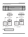
Modbus connection timeout
Modbus: Register 1280
A monitoring mechanism can be activated for every
Modbus/TCP connection in order for the bus coupler to
detect an error on the network (e.g., faulty cable) or in the
client (operating system crash or error in the TCP/IP
protocol stack) and respond accordingly. The monitoring
mechanism is activated via the relevant TCP connection
upon the first read or write procedure.
To change the timeout value for the relevant TCP
connection, write the new timeout value to the timeout table
to the special address 1280 using functions "fc 6" or "fc 16".
The value of this entry is the value of the timeout table. The
time is specified in milliseconds in the range from 200 ms to
65000 ms.
A timeout value of "0" deactivates the monitoring function.
Values between 1 ms and 199 ms, and values greater than
65000 ms generate exception response 3
(ILLEGAL DATA VALUE).
Net Fail reason
Address:
– Modbus: Register 2004
This register can be used to read the reason after setting the
Net Fail signal. If there is no Net Fail signal, the register is 0.
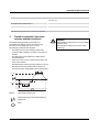
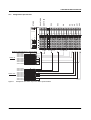
Command register
–
Modbus: Register 2006
The network interface command register can be used to
transmit commands with basic functions to the bus coupler
using the Ethernet host controller, e.g., PLC.
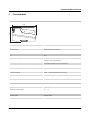
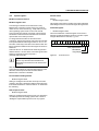
15 14 13 12 11 10 9 8 7 6 5 4 3 2 1 0
X X X
Reserved bits
Clear peripheral fault
Clear NetFail
Plug and play
Figure 20
61560030
Command word
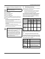
Connection monitoring with the new timeout
values is only activated after a Modbus/TCP
function has been executed on the relevant TCP
connection.
After the first access by a Modbus/TCP function, all other
access must be carried out using the entered timeout value.
Otherwise, fault response mode is activated and the
Modbus/TCP connection is disabled.
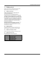
Process data watchdog timeout
–
Modbus: Register 2000
Setting or reading the timeout value for the process data
watchdog. The time is specified in milliseconds in the range
from 200 ms to 65000 ms. A timeout value of "0" deactivates
the watchdog.
Fault response mode
–
Modbus: Register 2002
Setting or reading the fault response mode. For information
on fault response mode settings, please refer to Section
"Setting the required fault response mode" on page 20.
8501_en_01
PHOENIX CONTACT
29