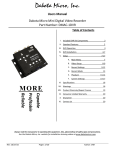
1
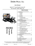
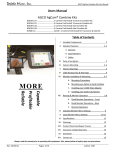
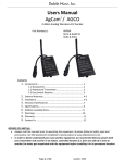
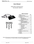
Dakota Micro, Inc. Users Manual AgCam®/ AGCO Part Number: QC‐9(7)M 1. 2. 3. 4. 5. 6. 7. 8. 9. Contents: Page Included Components .................................................................... 2 Standard Features a. Camera ......................................................................... 3 b. Monitor ......................................................................... 3 c. Cables ........................................................................... 3 Installation & Mounting a. Camera Installation & Mounting ................................ 4 b. Camera Function Plugs ............................................... 4 c. Cable Installation & Mounting .................................... 5 d. Monitor Installation & Mounting ................................ 6‐7 e. Trigger Event Operations ............................................ 8 Monitor & Remote Operation ........................................................ 8‐10 Standard Menu Settings ................................................................. 11‐12 Specifications .................................................................................. 13 Warnings ......................................................................................... 14 Warranty ......................................................................................... 15 Contact Us ...................................................................................... 16 Always read the manuals prior to operating this equipment, & please follow all safety signs and precautions. See DM Website for installation training videos at www.dakotamicro.com Page 1 of 16 Author: CNR User Manual DMAC-QC-9M-7M 1. INCLUDED MONITOR KIT COMPONENTS (PER MONITOR KIT) Description Picture Dakota Micro 9”or 7” LCD Monitor w/ Deutsch Quick connect Monitor wire harness Credit card style monitor remote w/ battery (styles vary by kit) AgCam Monitor Wire Harness for Monitors equipped with Quick Connect wire harness hookup (no triggers) AC power adaptor (styles vary by kit) Monitor U‐bracket w/ 4 wing bolts Monitor sun shield Cigarette lighter (12v) power adaptor (styles vary by kit) Accessory Camera Kit Contents (per camera kit – sold separately) Description AgCam® camera *NTSC/Silver camera shown PAL Cameras feature black body Picture Camera bracket w/ attached magnetic base Camera component bag: Allen wrench, (x2) nylon washers, (x2) retaining screws & camera pigtail 60’ power/video cable 20’ power/video cable Page 2 of 16 Rev: 3/17/14 Dakota Micro, Inc. Thank you for purchasing the AgCam®. The AgCam® is a durable, reliable surveillance system with the innovative ability to be quickly moved from one application to the next. Training videos are available on the Dakota Micro website at www.dakotamicro.com. 2. STANDARD FEATURES a. Camera Waterproof, shockproof, suitable for nearly any use. Minimum focal distance of 5”. Built‐in, high quality CCD camera with high performance infrared (IR) illuminator modules. IR has effective range of 45’+ in complete darkness. In‐line conditioner and surge suppressor prevents over/under powering of unit, preventing damage. Built‐in CDS light‐source sensor can automatically turn on/off the IR’s by detecting the light intensity of the environment. Our exclusive Photogray camera body lens darkens in bright conditions and becomes completely transparent under low light conditions. This lens is also transparent of infrared light, allowing the LED’s to penetrate even when it is darkened. Standard lens features 92° field of view (3.6mm). Optional lenses available include: 6mm, 12mm & 16mm. (A complete lens guide is available on our website at www.dakotamicro.com. Function plugs on Elite AgCam® versions allow for IR ON/OFF and switching of Forward/Reverse image. Removable/Replaceable camera tail. b. Monitors Features the latest in LCD technology. Color, brightness, contrast and volume controls that allow compensation for use in different environments. Selectable audio video inputs. Remote control & sun shield included. c. Cables Silicone jacket enables high flexibility in all temperatures. Our durable power/video extension cables come in 20’ and 60’ standard lengths and feature sturdy, watertight connectors. Additional power/video cables available in lengths of 10’, 30’, 40’, 50’ and 80's. Page 3 of 16 Author: CNR User Manual DMAC-QC-9M-7M 3. INSTALLATION & MOUNTING See DM Website for Installation Training Videos a. Camera Installation & Mounting 1. Camera Body 2. *IR Function Plug (Elite Only) 3. *MIR Function Plug (Elite Only) 4. Retaining Screw (x3) 5. Camera Tail Input 6. Camera bracket 7. Fiber Washer (x2) 8. Magnet 9. Magnet Nut b. Function Plugs (Elite Models Only) There are two function plugs on the bottom of each Elite Dakota Micro camera, near the camera tail. They will look like two additional screws at a slight angle recessed into the camera body. The function plugs utilize a polarized magnet to change camera functionality. 1) IR ON/OFF. This function plug requires a magnet to allow for the IR LED’s to function in low light conditions. If you remove the polarized magnet, the IR LED’s will NOT come on. 2) MIR/FOR. This function requires a magnet to activate/deactivate the mirror/forward function of the camera. Elite cameras are shipped from the factory with the MIR magnet installed. Temporary Mounting: For temporary mounting, it is recommended that you use the supplied 65# pull magnet. If using magnetic mount, fasten camera cable with a zip tie or other style fastener. This will act as a “safety wire” in the event your camera is knocked loose for some reason. When selecting a location, make sure that the equipment surface is clean of all foreign material and as flat as possible to ensure that the magnetic camera base will have good contact and not vibrate off. Page 4 of 16 Rev: 3/17/14 Dakota Micro, Inc. Permanent Mounting: For permanent mounting, it is recommended that you remove the magnet and attach to any solid surface with two (2) screws. After camera is securely mounted, plug power/video input into AgCam® extension power/video cable. Make sure they are securely attached and locked (¼ turn will lock the cables together). Suggestions for Mounting Camera: When determining the location for the camera it is always best to use a solid surface to minimize vibration. Ladders are not good mounting choices due to lack of stability. If you will be using your AgCam® for assisting in visibility for towing, you will want to position the camera so you can see the desired area and a portion of the vehicle/trailer in tow; this will give you some reference to distance. You will also want to use the mirrored setting in the monitor menu or remove the magnet in the MIR function plug on the camera so as to accurately represent left and right. This will give you the effect of looking in a rear view mirror. Camera Warnings NEVER RELY ON YOUR AGCAM®AS A SAFETY FEATURE. It is up to your discretion to keep your road travel and other operations safe. Your AgCam® will provide you with information only based on what it sees. Operation of machinery safety guidelines still apply. The AgCam® is equipped with an array of infrared light emitters which are invisible to the human eye. This feature will aid in low light conditions but has limitations. The effective range of the night vision feature is 1 to 45+ feet and will produce a monochrome image only. Do not attempt to drive machinery using this feature. c. Cable Installation & Mounting There are two (2) lengths of cable with your camera system: One (1) 20’ and one (1) 60’. If you would like to purchase different or additional cable lengths, please contact your dealer where you purchased your AgCam®. Cable Warnings Cable routing is important. Where you choose to run the cables should not interfere with the normal operation of the machine or any safety equipment. ALWAYS be aware of any “pinch points” or other potential hazards to the cable. Secure all cables to vehicle/equipment using cable clips, zip ties or other style fastener. If you intend to use your AgCam® for short length PTO operated implement, avoid excess cable lengths if possible. When you decide on a location you should fix the camera to a permanent bracket using ¼ inch bolts, and attach any loose cable securely so there is no chance of entanglement in the PTO or other moving parts. If you use your AgCam® to monitor a combine hopper or other combine operations, take care to remember that combines have many moving parts. Use extreme care when routing cables, and it is strongly recommended that you use bolts to secure the camera. While it would be sufficient to use the magnetic base for monitoring purposes during road travel, it is advised to secure the camera with bolts during operation of the combine. Page 5 of 16 Author: CNR User Manual DMAC-QC-9M-7M d. Monitor Installation & Mounting Mounting: Remove your monitor carefully from packaging, and inspect all mounting hardware. Mounting location is the most important part of the monitor installation to ensure maximum visual benefit from your AgCam® system. Keep in mind: Least direct sunlight. Keeping your monitor out of direct sunlight will prolong the life of the unit as well as ensure optimum visibility Does not obstruct your view Does not interfere with the normal operation of vehicle WARNING: Dakota Micro, Inc. is not responsible for any damages caused to your monitor, or yourself, due to the improper installation or use of a suction cup monitor mount, whether it be product sold by DM or product purchased from another source. Dry mount the monitor to the included universal mounting bracket by: 1. Holding monitor U‐bracket in place on monitor 2. Attach bracket with included wing bolts Once you have attached the monitor to the mounting bracket, follow these steps to finalize the installation. 1. With the mount and monitor attached, find and mark the desired position for the monitor. 2. Remove the monitor from the mount. 3. Attach the monitor to the mount and tighten the wing nut. Page 6 of 16 Rev: 3/17/14 Dakota Micro, Inc. Installation: Monitor Wire Harness Detail: 1) AV1 ‐ Video Input 2) AV2 ‐ Video Input 3) AV3 ‐ Video Input 4) AV4 ‐ Video Input 5) RCA‐Video Output (Non‐functional) 6) Power Input* 7) Input to Monitor Page 7 of 16 Author: CNR User Manual DMAC-QC-9M-7M Power: 12v Power: 1. Attach the power input connector (8 above) to your included 12v cigarette lighter adaptor**. 2. Plug cigarette lighter adaptor into 12v power source. *There is a small in‐line glass fuse located on the red power wire. When replacing blown fuses, use a MAX 2amp glass fuse. **There is a small glass fuse located inside the tip of the 12v portion of the power adaptor. When replacing blown fuses, use a MAX 4amp glass fuse. Hardwire Power (7.5 amp maximum circuit capability): 1. Contact your local AgCam® dealer for available hardwire power adaptors. e. Trigger Event Operations: Camera selection Event trigger wires are as follows: Camera 1 – Green Camera 2 – Purple Camera 3 – Gray Camera 4 – White Event trigger wires can be attached to any 12v positive event. This will cause the monitor to change to that camera, regardless of the state of the monitor (i.e. ON/OFF or channel selection). The most recent event will be the primary display, so if two video channels (AV1 & AV2) are attached to an event output, the one that happens last will change the monitor to its respective camera view. The wires can be attached to any positive output 10.5v to 16.9v switch or supply to cause the monitor to automatically switch the unit to its respective channel camera. For example; if you were to attach the AV1 wire to a positive output from an unloading auger on a combine, the monitor would switch from channel 2, 3, or 4 to channel 1 when the auger is extended. The event circuit should be neutral in its normal state and change to HIGH (+12v) when the event is considered to be active. 4. MONITOR & REMOTE OPERATION Turn the monitor on only after it has been securely mounted, supplied with power, and the cameras are connected. (9” Monitor shown. Actual button locations on 7” monitor may vary slightly): Page 8 of 16 Rev: 3/17/14 Dakota Micro, Inc. 1 Output Jack Headphone Jack 2‐4 FOR USE ONLY WITH Quad Processor 2 3 Full Screen Duplex Screen When connected to DM Quad, will show cameras 1/2/3/4 each time pressed When connected to DM Quad will show cameras 1 /4 and cameras 2 /3 each time pressed 4 Quad Screen When connected to DM Quad will display all 4 cameras connected 5 ‐ Key To decrease parameter 6 + Key To increase parameter 7 MENU To switch menu selection, press multiple times. To go to next icon, use + 8 AV Key Switches between AV1, AV2, AV3, & AV4 9 POWER Turns monitor ON/OFF 11‐12 ports located on sides and bottom of monitor 10 USB Port Input for optional cable when using a computer connected to the VGA port (duplicates image from input device, cable not available from DM) 11 Quad Plug USB female connector for Quad processor 12 VGA Input Input for VGA from computer or other console (duplicates image from input device, cable not available from DM) Page 9 of 16 Author: CNR User Manual DMAC-QC-9M-7M Remote POWER ON/OFF Mute Enable/Disable sound Flip image Left/Right Flip image Up/Down Navigation Arrows MENU Enters the menu Also acts as “enter” button in menu settings Adjusts screen display modes Reset your selection Enables timer that will turn off monitor Superimpose a grid on screen Aspect Ratio adjustment A/V switching (camera selection) Getting Started: 1. Power on monitor by pushing “POWER” button on the face of monitor or remote. 2. If you do not see video from your camera, push the AV button on monitor or SEL button on remote. Repeatedly pushing the AV or SEL button will cycle through the video channels. 5. STANDARD MENU SETTINGS Press the MENU key on the monitor or remote. Use the – and + keys on the monitor or the left and right arrow keys on the remote to move through the icons at the top of the screen. 1. Use the MENU key on the monitor (up and down arrows on remote) to select an item under each section. Selected menu items turn red. 2. Use – or + on the monitor (left and right arrows on remote) to change the value of the highlighted item. 3. To exit: Page 10 of 16 Rev: 3/17/14 Dakota Micro, Inc. a. Press the – or + key on the monitor (left or right arrow on remote) multiple times till the menu goes away b. Allow monitor to time out (approximately 5 seconds). PICTURE BRIGHT: Adjusts the brightness of the image CONTRAST: Adjusts the contrast of the image COLOR: Adjusts the color of the image TINT: Adjust tint of image (appears only when camera is plugged in) RESET: Returns settings to default VOLUME VOLUME: Adjusts the volume level OPTION CAMERA 1: AV1 event trigger delay time CAMERA 2: AV2 event trigger delay time CAMERA 3: AV3 event trigger delay time CAMERA 4: AV4 event trigger delay time ROTATE: Invert image on screen Page 11 of 16 Author: CNR User Manual DMAC-QC-9M-7M SYSTEM LANG: Select your language (English default) SOURCE: Adjusts the AV input source (AV1 default) GUIDE LINES: Super imposes a grid on your monitor screen (select ON or OFF) PRESET SLEEP: Enables sleep timer delay setting (in minutes) AV1: Enable (ON) or Disable (OFF) AV1 AV2: Enable (ON) or Disable (OFF) AV2 AV3: Enable (ON) or Disable (OFF) AV3 AV4: Enable (ON) or Disable (OFF) AV4 VGA: Enable (ON) or Disable (OFF) VGA input Page 12 of 16 Rev: 3/17/14 Dakota Micro, Inc. 6. SPECIFICATIONS A. Camera: Effective Picture Elements Image Pick‐up Device Horizontal Resolution Minimum Illumination S/N Ration Auto Electronic Shutter Auto White Balance Auto Gain Control Auto Iris Control Scanning System Gamma Characteristic Lenses Furnished Synchronous System Back Light Compensation Video Output Operating Temp. Construction Waterproofing criteria Dimensions B. LCD Monitor: Screen Size Overall Size Weight Power input Color System Operating Temp. Touch Panel Brightness Resolution (HxV) Contrast Viewing Angle Operating Voltage 510*492 SONY 1/3” Super HAD CCD sensor 540 Horizontal lines 0 LUX @ F2.0 More than 48dB 1/60s~1/100,000s, ON/OFF Switch‐able Color Temperature: 2500K~9500K High/Low Switch‐able Video‐Drive Iris Control Interlace 2:1 0.45 Board Lens 3.6mm/F2.0, Photogray Body Internal, Negative sync. On/Off Switch‐able 1 Vp‐p/75 Ohms. ‐45°F~150°F (‐42°C~66°C) Aluminum Case IP 68/69 53x58 (L) mm (Body Only) 9” (16:9) digital panel/7” (16:9) digital panel 235(L)X155(W)X36.5(H)mm 600g AC 10.5‐16.9V, 1,200 ma (2 cameras) NTSC/PAL auto switch ‐30°F~130°F (‐34°C~+54°C) 4‐Wire resistance (optional function) 400cd/m2 800(RGB)x480 500:1 L/R: 70° Up: 70° Down: 60° Min. 12v (Check monitor label for specific voltage range) Page 13 of 16 Author: CNR User Manual DMAC-QC-9M-7M 7. WARNINGS 1) To avoid electrical shock and maintain optimal functionality, do not open the enclosures. High voltage may be present and there are no user serviceable parts inside. All warranties will be void should any enclosures be tampered with in any way. 2) Do not use any harsh chemical solvents, cleaning agents or corrosive detergent to clean away dirt on the surface of the screen or lens. 3) Our photo‐chromic camera lenses have been made impact‐resistant and have been drop‐ball tested according to Sec. 3.84,21 CRF BUT ARE NOT UNBREAKABLE. Because they have been hardened chemically, they show no stress pattern. Inspect your lenses frequently. Chipped or scratched surfaces will reduce protection. Such lenses should be replaced only by the manufacturer. 4) This camera uses a special coated optic lens with photo chromatic properties; if the lens needs to be replaced we require that it be returned to the factory. 5) Power to cameras is not interrupted by turning off monitor; 12v power source must be terminated when not in use to avoid battery drain. To avoid this problem be sure when hard wiring a unit, use a fused circuit. 6) Do not use your Dakota Micro camera system for anything other than legal surveillance and observation uses. Dakota Micro, Inc. is not liable for any illegal or nefarious usage. Page 14 of 16 Rev: 3/17/14 Dakota Micro, Inc. 8. CONSUMER LIMITED WARRANTY LIMITED WARRANTY Subject to the disclaimer, limitations and other directions stated hereafter, Dakota Micro, Inc. warrants that the Product will be free from defects in material and workmanship for periods as stated hereafter from the date of original purchase. THIS WARRANTY IS EXPRESSLY MADE IN LIEU OF ANY AND ALL OTHER WARRANTIES, EXPRESS OR IMPLIED, INCLUDING THE IMPLIED WARRANTIES OF MERCHANTABILITY OR FITNESS. THE EXCLUSIVE REMEDY OF THE BUYER IS LIMITED TO REPAIR OR REPLACEMENT OF THE PRODUCT. EXCEPT AS STATED IN THIS WARRANTY, DAKOTA MICRO SHALL NOT BE LIABLE FOR ANY LOSS, INCONVENIENCE, OR DAMAGE, INCLUDING DIRECT, SPECIAL, INCIDENTAL, OR CONSEQUENTIAL DAMAGES, RESULTING FROM THE USE OR INABILITY TO USE THE PRODUCT, WHETHER RESULTING FROM BREACH OF WARRANTY, NEGLIGENCE, STRICT LIABILITY OF ANY OTHER LEGAL THEORY. Any oral statements or representations made by anyone which are contrary to or at variance with the terms stated in this LIMITED WARRANTY are void. Dakota Micro will, at its option, either repair the defect or replace the defective Product or part thereof with a new or remanufactured equivalent at no charge to the purchaser for parts or labor for the period of three (3) years for AgCam®/EnduraCam® cameras, two (2) years for AgCam®/EnduraCam® monitors, quads and Wireless Ranch Hands, Eighteen Months (18) for all Overview Cameras & Monitors and one (1) year for Mini DVR, cables and all other accessories. The Dakota Micro limited warranty periods outlined above apply throughout the United States and Canada only. A one (1) year maximum limited warranty for all Products applies to all other geographic locations unless otherwise stated in writing by Dakota Micro. This limited warranty does not apply to any issues connected with appearance that have no relation to the performance of the Product nor to any Product the exterior of which has been damaged or defaced, which has been subjected to improper voltage or other misuse, abnormal service or handling, or which has been altered or modified in design or construction. In order to enforce the rights under this limited warranty, the purchaser should follow the steps set forth in the complete Dakota Micro “Warranty & Repair Policy” listed at www.dakotamicro.com , and provide proof of purchase to Dakota Micro. Neither the sales personnel of Dakota Micro nor any dealer or any other person is authorized to make any warranties other than those described herein, or to extend the duration of any warranties beyond the time periods described herein. The warranties described herein shall be the sole and exclusive warranties and remedies provided by Dakota Micro. Correction of defects, in the manner and for the period of time described herein, shall constitute complete fulfillment of all liabilities and responsibilities of Dakota Micro to the purchaser with respect to the Product, and shall constitute full satisfaction of all claims. In no event shall Dakota Micro be liable or in any way responsible for any damages or defects in the Product which were caused by repairs or attempted repairs performed by anyone other than Dakota Micro. Some states do not allow the limitation or exclusion of incidental or consequential damages, so said limitation may not apply to you. Any action at law, suit in equity, or other judicial proceeding for the enforcement of any right provided for herein or otherwise, or with respect to any claim that a purchaser may have against Dakota Micro shall be instituted only in the Courts of the State of North Dakota, either in the state district court located in Wahpeton, North Dakota or in Federal District Court location in Fargo, North Dakota. Without regard to conflicts of law principles, the laws of the state of North Dakota shall govern the interpretation and enforcement of the terms of this Limited Warranty and all aspects of the relationship between Dakota Micro and the purchaser. This warranty gives you specific legal rights and you may also have other rights, which may vary from state to state. Page 15 of 16 Author: CNR User Manual DMAC-QC-9M-7M 9. CONTACT US Dakota Micro Inc. products, specifications, pricing and programs are subject to change without prior notice. Dakota Micro Inc. reserves the right to make design changes at any time without obligation to retroactively install them on previously sold units. Dakota Micro, Inc. 1 866 462-4226 www.dakotamicro.com 8659 148th Ave. SE Cayuga, ND 58013 Page 16 of 16 Rev: 3/17/14