1
RX113 Family
Capacitive Touch API User’s Manual
EU00162
Rev.1.00
December 5, 2014
Introduction
The Renesas Capacitive Touch Application Program Interface (API) has been created to allow users of the Capacitive
Touch Sensing Unit (CTSU) on the RX113 Group devices to easily add capacitive touch handling capability into their
application. This application note focuses on using the API and integrating it with your application program.
This API requires the hardware configuration for the CTSU module.
The API source files comply with the Renesas RX compiler only.
Target Device
The following is a list of devices able to use this API:
RX113 Group
When using this application note with other Renesas MCUs, careful evaluation is recommended after making
modifications to comply with the alternate MCU.
Related Documents
Firmware Integration Technology User’s Manual (R01AN1833EU)
Board Support Package Firmware Integration Technology Module (R01AN1685EU)
Adding Firmware Integration Technology Modules to Projects (R01AN1723EU)
RX113 Capacitive Touch Evaluation System Quick Start Guide (EU00161)
Contents
1.
Overview ........................................................................................................................................... 2
2.
API Information.................................................................................................................................. 3
3.
Usage Notes...................................................................................................................................... 5
4.
Demo Project................................................................................................................................... 11
Website and Support ............................................................................................................................... 12
EU00162 Rev.1.00
August 12, 2014
Page 1 of 12
Capacitive Touch API
1. Overview
This API is written to configure the CTSU peripheral on the Renesas MCUs. The API also provides the user with
ability to perform simple processing on measurements made by the CTSU for each channel and then treat each channel
as a Touch Button, or group channels and use them as linear or circular sliders. The API inherently depends on the user
to provide valid configuration values for each Special Function Register (SFR) of the CTSU. The user should obtain
these values by performing calibration with software such as Workbench 6. The demonstration projects provided with
this API provide an example of how the API uses the calibrated configuration values, a simple filter technique to
smooth data measured for each channel, and determine if a channel is being touched. The user can evaluate these
demonstrations with the RX113 CapTouch MCU Board and it’s daughter boards.
1.1
Features
Below is a list of the features supported by the Touch API.
1.2
Initialize the CTSU hardware
Configure for either self-capacitance measurement or mutual capacitance measurement mode
Provide hooks to use parameters generated by Capacitive Touch calibration software
Read and modify internal threshold and filtering parameters
Selectively enable and disable channels
Enable and disable drift compensation
Overall File structure
The API structure is as follows:
r_ctsu_rel – Contains a modified Workbench6 project as a base for driving the overall capactive touch sensing solution.
r_touch – The lower layer containing calls into the r_ctsu_rel layer which is responsible for controlling the CTSU
operation.
r_touch_button – Layer which uses the functions and variables located in r_touch and r_ctsu_rel to monitor and report
the status of touch sensing channels which are intended to operate as buttons.
r_touch_slider – Layer which uses the functions and variables located in r_touch and r_ctsu_rel to monitor and report
the status of touch sensing channels which are logically and physically grouped to operate as linear slider or circular
slider (wheel).
EU00162 Rev.1.00
August 12, 2014
Page 2 of 12
Capacitive Touch API
2. API Information
This Middleware API follows the Renesas API naming standards.
2.1
Hardware Requirements
This middleware requires your MCU support the following peripherals:
2.2
CTSU module peripheral
Hardware Resource Requirements
This section details the hardware peripherals that this middleware requires. Unless explicitly stated, these resources
must be reserved for the middleware and the user cannot use them
2.3
Capacitive Touch Sensing Unit (CTSU)
Software Requirements
The API uses a modified Workbench 6 project located under r_ctsu_rel.
2.4
Supported Toolchains
This middleware is tested and working with the following toolchains:
2.5
Renesas RX Toolchain v2.10
Header Files
There are three header files which contain API calls available to the user. These are:
r_touch_if.h
r_touch_button_if.h
r_touch_slider_if.h
The API configuration header files allow the user to change the following parameters. The effect of modifying these
files reflects in the private files for each layer. The configuration files are as follows:
r_touch_config.h – Allows the user to enable or disable parameter checks
r_touch_button_config.h – Allows the user to specify individual or default values for the following:
o
Transmit and Receive channel number for each button
o
Debounce counter
o
Repeat delay counter
o
Repeat rate count
o
Number of scans for which button is determined as pressed before generating a short hold event
o
Number of scans for which button is determined as pressed before generating a long hold event
o
Enable/disable events for press, short press-and-hold, long press-and-hold, repeat events on press
periodically
o
Function to call when an event occurs
r_touch_slider_config.h – Allows the user to specify default values used in the slider position calculations. The
values configured are the following:
o
Slider type – Linear or Circular
o
Channels used for the slider
o
Maximum value generated after normalization
o
Apply normalization to the channel data
o
Value used for normalization
EU00162 Rev.1.00
August 12, 2014
Page 3 of 12
Capacitive Touch API
o
Weight of running average for each channel, used to smooth data.
o
Weight of running average for previous sum of focus channels used as cutoff threshold.
o
Absolute threshold for sum of slider values
EU00162 Rev.1.00
August 12, 2014
Page 4 of 12
Capacitive Touch API
3. Usage Notes
The R_Touch API is intended to be used with a workbench 6 project which configures the CTSU for measurement and
updates variables which monitor the status of touch on Touch Sense channels which are enabled.
3.1
R_Touch
The R_Touch layer is responsible for controlling the CTSU operation and generates data to be used by higher layers.
The R_Touch layer accesses functions and variables defined in the r_ctsu_rel layer to control operation of the CTSU.
The user can access some of the important configuration settings created by workbench through the R_Touch_Open
functions using arguments. Values returned to the user include settings for intial thresholds, hysteresis, and SFR values
for diffusion control, offset0, and offset1 which are unique for each channel. The user may also specify a callback
function which will be executed once a single scan cycle is completed. The callback function is called from an interrupt.
The user is therefore advised to avoid while loops and limit the amount of processing performed within this function.
The callback function should be ideally used to unlock semaphores and indicate to other entities that a scan has
completed. The R_Touch_Open function also initializes the CTSU by means of the r_ctsu_rel layer.
After the CTSU has been initialized, the user must call the R_Touch_Process periodically with the option
TOUCH_OPTION_AUTO_SCAN to enable a new scan cycle after all post measurement processing is complete. If the
user provides the first argument which is not a NULL pointer, then the function returns the location which contains the
raw result data.
Additionally, the R_Touch_Read function allows the user to access the current value of variables such as the
difference between the reference count and the sensor count (delta count), or the Touch judgment counter.
3.2
R_Touch_Button
The R_Touch_Button layer is created to process data from a channel and treat it as a button. Global variables present
within the r_ctsu_rel directory are constantly modified when the CTSU is operational. The R_Touch_Button layer
accesses the needed values from the lower layers and determines whether a channel is being touched. Depending upon
the configuration of each button, multiple events can be triggered when the corresponding conditions are valid. The
primary tasks that a user may need are detailed below.
3.2.1
Adding a button
In order to add a button, one needs to first configure/calibrate a CTSU channel as a button using the Workbench 6
software. The lower level functions which process buttons are KeyProcess(), and KeyCalibrationProcess(). These
functions eventually update bits in g_real_touch_info and g_touch_result depending upon whether a channel is being
touched. The API will fail to report the correct status of the button if configuration and calibration of the CTSU channel
is not performed using Workbench 6.
Once calibration and configuration with Workbench 6 has been performed, the user can then modify the configuration
files controlling the API. The configuration file for buttons is r_touch_button_config.h and should be located under
the r_config directory. One may use the r_touch_button_config_reference.h file as a starting point which uses the
RX113 Captouch Wheel/Slider/Buttons daughter board configuration.
To add a new button in Self-Capacitance mode, simply add to the configuration file the following statement:
#define TOUCH_BUTTON_CFG_BUTTONn_CHANNEL_RX
(m)
Where n is a number from 0 to the maximum number of channels available with the CTSU (and configured with
Workbench 6). And m is the touch sensor channel number (TSm).
To add a new button in mutual capacitance mode, add the following two statements to the configuration file:
#define TOUCH_BUTTON_CFG_BUTTONn_CHANNEL_TX
(p)
#define TOUCH_BUTTON_CFG_BUTTONn_CHANNEL_RX
(m)
Where p is the channel acting as the transmit electrode for the button with m ≠ p.
Repeat this procedure for all buttons configured in Workbench 6.
3.2.2
Configuring a button
Once a button has been added, additional configuration options are available to further modify the behavior of all or
each individual button. If all buttons are expected to exhibit similar behavior then preprocessor definitions under basic
configuration options should be modified. These adjustments are as below:
EU00162 Rev.1.00
August 12, 2014
Page 5 of 12
Capacitive Touch API
TOUCH_BUTTON_CFG_DEFAULT_DEBOUNCE_COUNT – Defines the number of consecutive iterations for
which the lower layers must determine a channel is touched before a button is considered as pressed.
TOUCH_BUTTON_CFG_DEFAULT_RPT_DELAY_COUNT – Defines the number of iterations between the press
event and the first repeat event.
TOUCH_BUTTON_CFG_DEFAULT_RPT_RATE_COUNT – Defines the number of iterations after which a channel
determined to be touched executes the repeat event.
TOUCH_BUTTON_CFG_DEFAULT_SH_HOLD_COUNT – Defines the number of iterations after which a short
hold event is generated while a button is considered touched.
TOUCH_BUTTON_CFG_DEFAULT_LG_HOLD_COUNT – Defines the number of iterations after which a long
hold event is generated while a button is considered touched.
TOUCH_BUTTON_CFG_DEFAULT_STUCK_COUNT – Defines the number of iterations after which an event for
stuck button is generated as a button is considered to be touched.
TOUCH_BUTTON_CFG_DEFAULT_RELEASE_EVENT – Defines whether the button event generation is enable
when the channel is determined to be not touched after being touched.
TOUCH_BUTTON_CFG_DEFAULT_PRESS_EVENT – Defines whether the button event generation is enabled
when the channel is touched and considered as pressed.
TOUCH_BUTTON_CFG_DEFAULT_REPEAT_EVENT – Defines whether repetitive button event generation is
enabled while button is considered pressed.
TOUCH_BUTTON_CFG_DEFAULT_SHORTHOLD_EVENT – Defines whether an event is generated when channel
is touched for the duration of SH_HOLD_COUNT.
TOUCH_BUTTON_CFG_DEFAULT_LONGHOLD_EVENT – Defines whether an event is generated when channel
is touched for the duration of LG_HOLD_COUNT.
TOUCH_BUTTON_CFG_DEFAULT_CALLBACK – Defines the function which gets called when an event occurs.
This function gets passed the event type and the button/key identifier as arguments.
3.2.3
Advanced configuration options
When creating buttons which behave differently from each other, the user needs to specify parameters other than the
basic default parameters as mentioned above. To assign unique parameters to individual buttons, enable the
preprocessor TOUCH_BUTTON_CFG_ADV_DEFAULT and assign as shown below
#define TOUCH_BUTTON_CFG_BUTTONn_xxxxxxxx
(yyy)
Where n is 0 … number of channels configured as buttons.
These unique values will replace the corresponding default values for button n in the file r_touch_button_private.h.
The user is advised to take a quick look at r_touch_button_private.h for further understanding.
3.2.4
Evaluating button state
Once a button has been properly configured, the user can call the function R_Touch_Button_Open to initialize the
buttons. If the user chooses to provide arguments other than NULL to the open function, then the particular values for
the configuration will be overridden.
After the button has been configured and initialized, the user must periodically call R_Touch_Button_Handler to
check if the button has changed states and if any events have occurred. Arguments passed to the handler are button
handles and the number of handles passed (as an array). Handles to all buttons are obtained as a return value through
R_Touch_Button_Open when no arguments are passed to it. When arguments are passed to the handler, only those
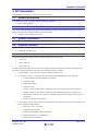
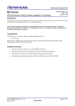
buttons are checked for which handles are passed. The following is an example code for checking only 3 channels out
of a total of 12 configured as buttons using basic configuration in self-capacitance mode.
EU00162 Rev.1.00
August 12, 2014
Page 6 of 12
Capacitive Touch API
#include <stddef.h>
#include "r_touch_if.h"
#include "r_touch_button_if.h"
touch_button_hdl_t* all_button_handles;
touch_button_key_t last_button;
void R_Touch_Button_Callback( touch_button_key_t key, touch_button_event_t event )
{/* Verify by placing a breakpoint at the nop */
nop();
}
void main(void)
{
/* Find out how many buttons are currently in use,
* and get the configuration location */
all_button_handles = R_Touch_Button_Open(&last_button, NULL, NULL);
while(1)
{/* Check only buttons 9, 10, and 11. */
if( g_ctsu_soft_mode == CTSU_FINISH_MODE
|| g_ctsu_soft_mode == CTSU_READY_MODE )
{
R_Touch_Button_Handler(&all_button_handles[9],3);
}
}
}
Figure 1: Test code for R_Touch_Button
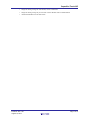
#define
#define
#define
#define
#define
#define
#define
#define
#define
#define
#define
#define
TOUCH_BUTTON_CFG_BUTTON0_CHANNEL_RX
TOUCH_BUTTON_CFG_BUTTON1_CHANNEL_RX
TOUCH_BUTTON_CFG_BUTTON2_CHANNEL_RX
TOUCH_BUTTON_CFG_BUTTON3_CHANNEL_RX
TOUCH_BUTTON_CFG_BUTTON4_CHANNEL_RX
TOUCH_BUTTON_CFG_BUTTON5_CHANNEL_RX
TOUCH_BUTTON_CFG_BUTTON6_CHANNEL_RX
TOUCH_BUTTON_CFG_BUTTON7_CHANNEL_RX
TOUCH_BUTTON_CFG_BUTTON8_CHANNEL_RX
TOUCH_BUTTON_CFG_BUTTON9_CHANNEL_RX
TOUCH_BUTTON_CFG_BUTTON10_CHANNEL_RX
TOUCH_BUTTON_CFG_BUTTON11_CHANNEL_RX
(0)
(1)
(2)
(3)
(4)
(5)
(6)
(7)
(8)
(9)
(10)
(11)
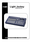
Figure 2: Button Channel Configuration
3.3
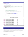
R_Touch_Slider
In capacitive touch sensing, a slider is a collection of closely located electrodes with a pattern that allows estimating an
interpolated location of a touch. For example, if the user is touching a position midway between two elements of a two
channel slider, then the position of the touch should be at 50% of the maximum absolute output. The R_Touch layer
activates layers below it to run the CTSU to perform measurements on the channels and update related global data
variables. The R_Touch_Slider layer selectively uses some of these global variables to compute the position of the
touched location on a collection of channels. The R_Touch_Slider allows the user to create two types of sliders, linear
sliders and circular sliders in Self-Capacitance mode only.
EU00162 Rev.1.00
August 12, 2014
Page 7 of 12
Capacitive Touch API
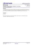
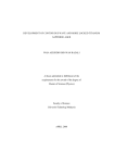
Linear slider
Circular slider
Figure 3: Self Capacitance Demonstration Board
The primary tasks a user may need to accomplish with a slider are detailed in the following material.
3.3.1
Adding a Slider
In order to add a slider, the user must first configure/calibrate the CTSU using the Workbench 6 software. This allows
the variables in the lower levels to be activated and updated when the CTSU is operational. The R_Touch_Slider
primarily uses the g_dcount variable array which is updated by the lower levels to determine the position. Without
proper configuration with Workbench 6, this variable may not be updated periodically.
After configuration and calibration is performed with Workbench 6, the user can then modify the configuration files
controlling the API. The configuration file for buttons is r_touch_slider_config.h and should be located under the
r_config directory. One may use the r_touch_slider_config_reference.h file as a starting point which uses the RX113
Captouch Wheel/Slider/Buttons daughter board configuration.
To add a slider add the following equivalent statements to r_touch_slider_config.h.
#define TOUCH_SLIDER_CFG_SLIDERn_TYPE
(m)
Where n = 1 to number of sliders to use, and m is the type of slider. If m = 0, then the calculations on channel readings
assume a linear slider. If m = 1, then the calculations on channel readings assume a circular slider/wheel.
After declaring the type for slider ‘n’, the user needs to define the channels used for the slider position calculations.
This is done as follows:
#define TOUCH_SLIDER_CFG_SLIDERn_CHANNELp
(q)
Where p = is the element number (0 to number of channels part of the slider), and q = channel used for element p.
3.3.2
Configuring a slider
Once a slider has been added, additional configuration options allow the user to change the
behavior of the calculations performed for the position. For example, the user may want to
configure a circular slider to report the position of touch as an absolute value from 0˚ to 360˚. Basic
configuration options available are as follows:
TOUCH_SLIDER_CFG_DEFAULT_USE_NORM – Defines if normalization is performed on each
channel.
TOUCH_SLIDER_CFG_DEFAULT_NORM – Defines the divisor value used to normalize a
channel measurement.
EU00162 Rev.1.00
August 12, 2014
Page 8 of 12
Capacitive Touch API
TOUCH_SLIDER_CFG_NORM_MAX – Indicates the maximum value generated for a channel
measurement after normalization. This value is co-dependent on divisor values used for each
channel.
TOUCH_SLIDER_CFG_DEFAULT_CH_AVG_WEIGHT – Weight of running average for each
channel, used to smooth data.
TOUCH_SLIDER_CFG_DEFAULT_PREV_SUM_WEIGHT – Weight of running average for
previous sum of focus channels.
TOUCH_SLIDER_CFG_DEFAULT_THRESHOLD – Cumulative sums below this value will not be
registered as a touch.
TOUCH_SLIDER_CFG_DEFAULT_CUTOFF – Indicates how far sum of slider values should fall
below running average to indicate inactive touch.
3.3.3
Advanced options
If the user needs to specify unique parameters for each individual slider, the user needs to set the preprocessor statement
TOUCH_SLIDER_CFG_ADV_DEFAULT to 0 for selecting advanced settings for each slider. When using the
advanced configuration option, the user can define and override individual configuration parameters for each slider with
the prefix to a preprocessor statement as shown below:
#define TOUCH_SLIDER_CFG_SLIDER1_xxxxxxxx
(yyy)
Note that the user can also define normalizations for individual slider channels as
#define TOUCH_SLIDER_CFG_SLIDERn_NORMp
(zzzzz)
Providing these advanced options will affect structure instances defined in r_touch_slider_private.h. The user is
recommended to take a quick look at how changes in the configuration file affect these instances.
3.3.4
Evaluating a slider
In order to acquire the position of a touch, the user must first call the initialization function R_Touch_Slider_Open and
provide the necessary arguments for each slider defined in the configuration. Necessary arguments include the mode of
operation of the slider, i.e. absolute or relative, the maximum value of the slider (in terms of position), a pointer which
gets assigned the location of the slider configuration, and the identifier for the slider i.e. TOUCH_SLIDERn, where n is
1 to last slider number defined in configuration file. If the configuration of the slider is performed correctly, then the
Open function will make the slider ready for operation.
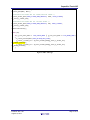
The user must then call R_Touch_Slider_Read periodically with the handle and pointer to a 16-bit signed integer
passed as an argument to retrieve the current position of touch. The return value from the Read function indicates if the
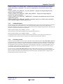
slider is currently being touched with position being reported in the integer. The following shows a snippet of code
demonstrating the usage of the API for a slider:
EU00162 Rev.1.00
August 12, 2014
Page 9 of 12
Capacitive Touch API
/* Capacitive Touch Sensing Unit initial setup
R_Touch_Open(NULL, NULL);
*/
/*Initialize the slider API for linear/vertical slider */
R_Touch_Slider_Open(TOUCH_SLIDER_MODE_ABSOLUTE, 1024, TOUCH_SLIDER1,
&g_touch_v_slider_hdl);
/*Initialize the slider API for circular slider */
R_Touch_Slider_Open(TOUCH_SLIDER_MODE_ABSOLUTE, 360, TOUCH_SLIDER2,
&g_touch_w_slider_hdl);
LedInitialization();
while (1U)
{
if( g_ctsu_soft_mode == CTSU_FINISH_MODE || g_ctsu_soft_mode == CTSU_READY_MODE )
{
R_Touch_Process(NULL,TOUCH_OPTION_AUTO_SCAN);
g_touch_v_slider_err = R_Touch_Slider_Read(g_touch_v_slider_hdl,
&g_slider_position);
g_touch_w_slider_err = R_Touch_Slider_Read(g_touch_w_slider_hdl,
&g_wheel_position);
}
}
Figure 4: Slider API usage
EU00162 Rev.1.00
August 12, 2014
Page 10 of 12
Capacitive Touch API
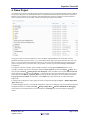
4. Demo Project
An e2studio project archive which demonstrates features provided by the API is included with this API User’s Manual.
The project is designed to run with the Renesas RX113 CapTouch Demonstration Kit, and demonstrates operation of
Buttons, wheel, and sliders in self-capacitance mode and demonstrates operation of buttons in mutual-capacitance
mode. The figure below shows the initial contents after importing the project with e2studio.
The project contains two build configurations, namely SelfMode, and MutualMode. The .cheat folder contains
parameter files which replace files in the r_ctsu_rel/TouchBase folder. When replacing the parameter file, remove the
suffix _ref_xxxx.h. Ensure that the file being replaced is for the correct build configuration. Proper operation of the
project is not guaranteed if you replace with r_ctsu_parameter_common_ref_self.h when building in MutualMode
configuration.
To import the project into e2studio, open an e2studio workspace (click the go to workbench button, if a new
workspace is created), right click in blank space within the Project Explorer tab and select Import → Import. Then
select the option General → Existing Projects into Workspace. Then select Next. Use the option Select archive file
and navigate to the zip file location using Browse… and select the file. The project should then appear in the Projects
section with the name RX113_CapTouch_Demos. Ensure the checkbox against the name is checked. The option for
Copy projects into workspace should be active. Select Finish. The project should now be visible in the Project
Explorer tab.
To change build configurations, simply change the current configuration through the Project → Build configurations
→ Set Active option.
To enable debugging the project, first build the configuration. Then select a debugging session which matches the build
configuration from those available under Run → Debug Configurations → Renesas GDB Hardware Debugging.
Ensure that the correct Debug hardware is selected under the tab Debugger for the selected hardware debugging
session.
EU00162 Rev.1.00
August 12, 2014
Page 11 of 12
Capacitive Touch API
Website and Support
Renesas Electronics Website
http://www.renesas.com/
Inquiries
http://www.renesas.com/inquiry
All trademarks and registered trademarks are the property of their respective owners.
EU00162 Rev.1.00
August 12, 2014
Page 12 of 12
Revision Record
Rev.
1.00
Date
December.05.14
Description
Page
Summary
—
First edition issued
A-1
Notice
1.
Descriptions of circuits, software and other related information in this document are provided only to illustrate the operation of semiconductor products and application examples. You are fully responsible for
the incorporation of these circuits, software, and information in the design of your equipment. Renesas Electronics assumes no responsibility for any losses incurred by you or third parties arising from the
use of these circuits, software, or information.
2.
Renesas Electronics has used reasonable care in preparing the information included in this document, but Renesas Electronics does not warrant that such information is error free. Renesas Electronics
assumes no liability whatsoever for any damages incurred by you resulting from errors in or omissions from the information included herein.
3.
Renesas Electronics does not assume any liability for infringement of patents, copyrights, or other intellectual property rights of third parties by or arising from the use of Renesas Electronics products or
technical information described in this document. No license, express, implied or otherwise, is granted hereby under any patents, copyrights or other intellectual property rights of Renesas Electronics or
others.
4.
You should not alter, modify, copy, or otherwise misappropriate any Renesas Electronics product, whether in whole or in part. Renesas Electronics assumes no responsibility for any losses incurred by you or
third parties arising from such alteration, modification, copy or otherwise misappropriation of Renesas Electronics product.
5.
Renesas Electronics products are classified according to the following two quality grades: "Standard" and "High Quality". The recommended applications for each Renesas Electronics product depends on
the product's quality grade, as indicated below.
"Standard": Computers; office equipment; communications equipment; test and measurement equipment; audio and visual equipment; home electronic appliances; machine tools; personal electronic
equipment; and industrial robots etc.
"High Quality": Transportation equipment (automobiles, trains, ships, etc.); traffic control systems; anti-disaster systems; anti-crime systems; and safety equipment etc.
Renesas Electronics products are neither intended nor authorized for use in products or systems that may pose a direct threat to human life or bodily injury (artificial life support devices or systems, surgical
implantations etc.), or may cause serious property damages (nuclear reactor control systems, military equipment etc.). You must check the quality grade of each Renesas Electronics product before using it
in a particular application. You may not use any Renesas Electronics product for any application for which it is not intended. Renesas Electronics shall not be in any way liable for any damages or losses
incurred by you or third parties arising from the use of any Renesas Electronics product for which the product is not intended by Renesas Electronics.
6.
You should use the Renesas Electronics products described in this document within the range specified by Renesas Electronics, especially with respect to the maximum rating, operating supply voltage
range, movement power voltage range, heat radiation characteristics, installation and other product characteristics. Renesas Electronics shall have no liability for malfunctions or damages arising out of the
use of Renesas Electronics products beyond such specified ranges.
7.
Although Renesas Electronics endeavors to improve the quality and reliability of its products, semiconductor products have specific characteristics such as the occurrence of failure at a certain rate and
malfunctions under certain use conditions. Further, Renesas Electronics products are not subject to radiation resistance design. Please be sure to implement safety measures to guard them against the
possibility of physical injury, and injury or damage caused by fire in the event of the failure of a Renesas Electronics product, such as safety design for hardware and software including but not limited to
redundancy, fire control and malfunction prevention, appropriate treatment for aging degradation or any other appropriate measures. Because the evaluation of microcomputer software alone is very difficult,
please evaluate the safety of the final products or systems manufactured by you.
8.
Please contact a Renesas Electronics sales office for details as to environmental matters such as the environmental compatibility of each Renesas Electronics product. Please use Renesas Electronics
products in compliance with all applicable laws and regulations that regulate the inclusion or use of controlled substances, including without limitation, the EU RoHS Directive. Renesas Electronics assumes
no liability for damages or losses occurring as a result of your noncompliance with applicable laws and regulations.
9.
Renesas Electronics products and technology may not be used for or incorporated into any products or systems whose manufacture, use, or sale is prohibited under any applicable domestic or foreign laws or
regulations. You should not use Renesas Electronics products or technology described in this document for any purpose relating to military applications or use by the military, including but not limited to the
development of weapons of mass destruction. When exporting the Renesas Electronics products or technology described in this document, you should comply with the applicable export control laws and
regulations and follow the procedures required by such laws and regulations.
10. It is the responsibility of the buyer or distributor of Renesas Electronics products, who distributes, disposes of, or otherwise places the product with a third party, to notify such third party in advance of the
contents and conditions set forth in this document, Renesas Electronics assumes no responsibility for any losses incurred by you or third parties as a result of unauthorized use of Renesas Electronics
products.
11. This document may not be reproduced or duplicated in any form, in whole or in part, without prior written consent of Renesas Electronics.
12. Please contact a Renesas Electronics sales office if you have any questions regarding the information contained in this document or Renesas Electronics products, or if you have any other inquiries.
(Note 1)
"Renesas Electronics" as used in this document means Renesas Electronics Corporation and also includes its majority-owned subsidiaries.
(Note 2)
"Renesas Electronics product(s)" means any product developed or manufactured by or for Renesas Electronics.
SALES OFFICES
http://www.renesas.com
Refer to "http://www.renesas.com/" for the latest and detailed information.
Renesas Electronics America Inc.
2801 Scott Boulevard Santa Clara, CA 95050-2549, U.S.A.
Tel: +1-408-588-6000, Fax: +1-408-588-6130
Renesas Electronics Canada Limited
1101 Nicholson Road, Newmarket, Ontario L3Y 9C3, Canada
Tel: +1-905-898-5441, Fax: +1-905-898-3220
Renesas Electronics Europe Limited
Dukes Meadow, Millboard Road, Bourne End, Buckinghamshire, SL8 5FH, U.K
Tel: +44-1628-585-100, Fax: +44-1628-585-900
Renesas Electronics Europe GmbH
Arcadiastrasse 10, 40472 Düsseldorf, Germany
Tel: +49-211-6503-0, Fax: +49-211-6503-1327
Renesas Electronics (China) Co., Ltd.
Room 1709, Quantum Plaza, No.27 ZhiChunLu Haidian District, Beijing 100191, P.R.China
Tel: +86-10-8235-1155, Fax: +86-10-8235-7679
Renesas Electronics (Shanghai) Co., Ltd.
Unit 301, Tower A, Central Towers, 555 Langao Road, Putuo District, Shanghai, P. R. China 200333
Tel: +86-21-2226-0888, Fax: +86-21-2226-0999
Renesas Electronics Hong Kong Limited
Unit 1601-1613, 16/F., Tower 2, Grand Century Place, 193 Prince Edward Road West, Mongkok, Kowloon, Hong Kong
Tel: +852-2265-6688, Fax: +852 2886-9022/9044
Renesas Electronics Taiwan Co., Ltd.
13F, No. 363, Fu Shing North Road, Taipei 10543, Taiwan
Tel: +886-2-8175-9600, Fax: +886 2-8175-9670
Renesas Electronics Singapore Pte. Ltd.
80 Bendemeer Road, Unit #06-02 Hyflux Innovation Centre, Singapore 339949
Tel: +65-6213-0200, Fax: +65-6213-0300
Renesas Electronics Malaysia Sdn.Bhd.
Unit 906, Block B, Menara Amcorp, Amcorp Trade Centre, No. 18, Jln Persiaran Barat, 46050 Petaling Jaya, Selangor Darul Ehsan, Malaysia
Tel: +60-3-7955-9390, Fax: +60-3-7955-9510
Renesas Electronics Korea Co., Ltd.
12F., 234 Teheran-ro, Gangnam-Ku, Seoul, 135-920, Korea
Tel: +82-2-558-3737, Fax: +82-2-558-5141
© 2014 Renesas Electronics Corporation. All rights reserved.
Colophon 4.0