1
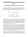
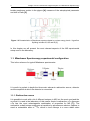
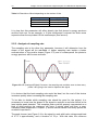
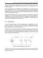
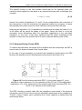
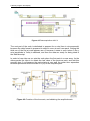
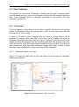
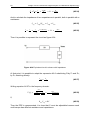
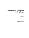
Previous numerical data treatment with MatLab
9
Chapter 2
MEASURING SYSTEM. ARCHITECTURE AND
ERRORS
All the elements in a circuit, either active or passive, could modify (introduce errors)
in amplitude or frequency the output data that is going to be measured. This is the
reason why, before analyzing in depth the data to obtain the photon’s energy
spectrum, it is always advisable to study the architecture of the instrumentation
system to receive the signal, in order to be sure that the data have as less error as
possible.
This chapter contains four well differentiate parts.
Section 2.1, will be dedicated to analyze the architecture of the measuring system
necessary to obtain the signal in order to determine which elements make up the
system analyzed.
In section 2.2 the actual system used in the laboratory will be compared with the
different devices that allow acquiring the amplifier’s signal. This section also contains
the study of the amplifier’s signal because it should ensure that the data acquisition
system (DAS) that is going to be bought complies all the requirements of the project.
It is essential to determine device’s features as the sampling frequency fs necessary
to obtain a good digital reconstruction of the signal, the number of bits (n) to obtain
accurate data, and finally the bandwidth, without forgetting that one of the goals of
the project is to design a low-cost equipment.
Section 2.3 will compare the errors caused by the actual type of wiring with the
effects obtained with an external divisor probe.
Finally Section 2.4 will analyze the whole system
2.1. Architecture of the instrumentation system
The system used in the laboratory consists in three basics elements (Figure 2.1): i)
amplifier; ii) wire type; iii) Data Acquisition System (DAS).
The amplifier send the signal through its output impedance composed of a resistance
(100 Ω) and an output inductance with a non-specified value in the manual.
The actual wire connexion is a 1 meter length coaxial cable that introduces an
impedance in form of capacitance (80 pF each meter length).