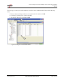
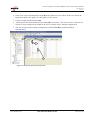
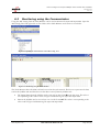
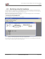
1
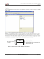
How to configure an Anybus CANopen slave module with TwidoSoft
SCM-7032-042
Rev 1.01
How to configure an Anybus CANopen
slave module with TwidoSoft
www.anybus.com
HMS Industrial Networks AB
Page 1 (29)
How to configure an Anybus CANopen slave module with TwidoSoft
SCM-7032-042
Rev 1.01
Document history
Revision
1.00
Date
2007-08-31
Description
Created
Author
Thorbjörn Palm
1.01
2008-03-14
Minor revision
Thorbjörn Palm
More information about the network and products
For further information about the Anybus products, please consult the HMS webpage, www.anybus.com.
The latest manuals, etcetera can be downloaded from that location.
The CANopen user organisation has a webpage on the Internet, www.can-cia.org. Several technical guides
about CANopen are available in or via this page.
www.anybus.com
HMS Industrial Networks AB
Page 2 (29)
How to configure an Anybus CANopen slave module with TwidoSoft
SCM-7032-042
Rev 1.01
Contents
1
Applicable Anybus products ...................................................................................................................4
2
Requirements ............................................................................................................................................4
3
Solution overview .....................................................................................................................................5
4
Anybus configuration...............................................................................................................................6
4.1
Anybus Slave configuration..............................................................................................................6
4.2
Anybus CompactCom configuration ................................................................................................6
4.3
Communicator configuration ............................................................................................................7
4.4
Anybus X-gateway configuration ...................................................................................................12
5
CANopen configuration .........................................................................................................................14
6
Testing .....................................................................................................................................................22
6.1
Monitoring in TwidoSoft ................................................................................................................22
6.2
Monitoring using the Communicator..............................................................................................26
6.3
Monitoring using the X-gateway ....................................................................................................27
www.anybus.com
HMS Industrial Networks AB
Page 3 (29)
How to configure an Anybus CANopen slave module with TwidoSoft
SCM-7032-042
Rev 1.01
1
Applicable Anybus products
The following table specifies the relevant Anybus products for this document.
Description
Name / Type
Anybus X-gateway
CANopen
Anybus Communicator
CANopen
Anybus-Slave
CANopen
Anybus-S Drive Profile
CANopen
Anybus CompactCom
CANopen
2
Requirements
The following equipment is needed to setup a successful configuration.
Description
Name / Type
Version
Telemecanique Twido PLC
TWDLMDA20DRT
-
PLC software
Twidosoft
3.5
Communicator configuration software
ABC Config Tool
2.34
X-gateway terminal software
HyperTerminal or TeraTermPro
5.1, 2.3
X-gateway Network Interface Addendum
Anybus X-gateway CANopen Slave,
Network Interface Addendum
1.02
X-gateway User Manual
X-gateway Generic User Manual
1.11
Communicator User Manual
Anybus Communicator for CANopen,
User Manual
2.51
Slave Drive Profile Fieldbus Appendix
Anybus-S CANopen Drive Profile,
Fieldbus Appendix
1.00
Slave Fieldbus Appendix
Anybus-S CANopen, Fieldbus
Appendix
2.04
CompactCom Network Interface Appendix
Anybus-CompactCom CANopen,
Network Interface Appendix
2.01
Power supply 24VDC
n.a.
n.a
Configuration cables
n.a.
n.a.
www.anybus.com
HMS Industrial Networks AB
Page 4 (29)
How to configure an Anybus CANopen slave module with TwidoSoft
SCM-7032-042
Rev 1.01
3
Solution overview
This application note describes how to configure an Anybus CANopen Slave product with a Schneider
Twido PLC. Below you can find an overview of the system described in this document. Other nodes may be
attached to the network, but are not necessary. Also make sure the network is terminated in a correct way.
The configuration is described in two steps.
1
The configuration of the communication parameters and the I/O data of the Anybus module are
described.
2
The PLC configuration is explained.
Note: This document is valid for all Anybus CANopen products, however sections written in italics describe
the configuration of a specific product.
The contents describe step by step how a configuration is done. This document assumes the reader is familiar
with industrial communication, CANopen networks and HMS Communicator and X-gateway.
PLC
PLC
Master
Master
CANopen
CANopen
CANopen Slave
CANopen
Slave
Anybus Communicator
Example of
Serial Network
Anybus X-gateway
Other network
i.e. Ethernet
Ethernet
PC
Client
Figure 1 Hardware connection overview.
www.anybus.com
HMS Industrial Networks AB
Page 5 (29)
How to configure an Anybus CANopen slave module with TwidoSoft
SCM-7032-042
Rev 1.01
4
Anybus configuration
The first step is to configure the baudrate and the node address. The Anybus Slave, Anybus Communicator
and Anybus X-gateway are configured by switches. Set the baud rate and node address switches in the
desired positions as seen below.
Note: The Anybus CompactCom is configured by messages send by the application.
The switches will be found next to the fieldbus connector, please see the respective manual or appendix for
details. The selected baud rate of the PLC and the Anybus module is to be set to the same rate. The baud rate
of the PLC is configured by the TwidoSoft software, please see Figure 21 Adding the Anybus module to the
CANopen network.
The switches are located as follows:
•
The switch closest to the fieldbus connector sets
the baudrate. Please see the table to the right.
Pos
Baudrate
Pos
Baudrate
0
(reserved)
5
250 Kbit/s
•
The next switch sets the 10x address.
1
10 Kbit/s
6
500 Kbit/s
•
The third switch sets the 1x address.
2
20 Kbit/s
7
800 Kbit/s
3
50 Kbit/s
8
1 Mbit/s
4
125 Kbit/s
9
(reserved)
In this case the baud rate switch is set to 6, thus the baud
rate used is 500kbit/s. The address switches are set to 0
and 1 respectively, thus the Node address is 1.
Note: Using the Anybus Slave the node address and baud rate can also be set by mailbox command.
In the following chapters the I/O configuration of the Anybus module is explained.
4.1
Anybus Slave configuration
The Anybus-S is initiated and configured via the host application interface using the mailbox interface. Refer
to the Anybus-S Fieldbus Appendix for details.
4.2
Anybus CompactCom configuration
The Anybus CompactCom is configured by messages send by the application. Refer to the CompactCom
Network Interface Appendix for details.
www.anybus.com
HMS Industrial Networks AB
Page 6 (29)
How to configure an Anybus CANopen slave module with TwidoSoft
SCM-7032-042
Rev 1.01
4.3
Communicator configuration
Start the Anybus Communicator and create a new configuration. Choose the CANopen fieldbus and the
desired size of the I/O data. The configuration differs depending on what type of data is used. Using PDOs
only, please see section Using PDOs only below. Using SDOs please see section Using SDOs.
Using PDOs only
In this case Automatic I/O Sizes is used. This implies the I/O size is depending on the sub-network
configuration, please see the note below.
Figure 2
Configuring the Fieldbus.
Note: Using the Automatic setting for the IO size, the amount of data configured for the fieldbus is
depending on the sub-network configuration. The PDO data will in that case be of the same size as
configured for the sub-network.
www.anybus.com
HMS Industrial Networks AB
Page 7 (29)
How to configure an Anybus CANopen slave module with TwidoSoft
SCM-7032-042
Rev 1.01
Using SDOs
When using SDOs the I/O sizes has to be set to user defined as shown below. In this case 10 bytes of I/O data
(PDO) is used.
Figure 3 Configuring the Fieldbus using PCP data.
Note: The IO size IN and Out, in this case 10 bytes, set the size of the PDOs. The number of bytes of SDOs
will depend on the data configured for the sub-network. The data configured for the sub-network indicates
the total I/O size. The number of bytes of SDOs is the difference between the data size configured for the subnetwork and the IO Size In and IO Size Out. In this case the total I/O size is 20 bytes (configured for the subnetwork) and the size of PDOs is 10 bytes. The size of the SDOs is then 20-10=10 bytes.
Sub-network data size
(20 bytes)
Figure 4
www.anybus.com
PDOs
IO Size In and Out
(10 bytes, byte 1-10)
SDOs
Sub-network data size - IO Size In and Out
(10 bytes, byte 11-20)
Configuring the size of the PDOs and SDOs in ABC Config Tool.
HMS Industrial Networks AB
Page 8 (29)
How to configure an Anybus CANopen slave module with TwidoSoft
SCM-7032-042
Rev 1.01
Figure 5
Configuring the ABC.
In this case a loop back dongle at the serial connection of the Communicator is connected. To loop data the
generic data mode is selected, all other values are left at their defaults. The next step is to configure the subnetwork.
Figure 6
Configuring the Sub-Network.
In this case the bit rate is set to 19200 bits/s, all other parameters are left at their default values. Right click
on new node and add consume and a produce transaction as shown below.
www.anybus.com
HMS Industrial Networks AB
Page 9 (29)
How to configure an Anybus CANopen slave module with TwidoSoft
SCM-7032-042
Rev 1.01
Figure 7
Configuring the consume transaction.
Leave the settings for the consume transaction at the defaults as shown above.
For the produce transaction the update time is set to 500ms as shown below.
Note: The update time for the produce transaction is to be set to less than the offline timeout time for the
consume transaction.
Figure 8
www.anybus.com
Configuring the produce transaction.
HMS Industrial Networks AB
Page 10 (29)
How to configure an Anybus CANopen slave module with TwidoSoft
SCM-7032-042
Rev 1.01
Right click on the produce and consume transaction respectively and select add data. In this case 20 bytes of
data is used.
Figure 9
Configuring the consume data.
The next step is to save the configuration. Then connect to the Communicator and download the
configuration to the module.
www.anybus.com
HMS Industrial Networks AB
Page 11 (29)
How to configure an Anybus CANopen slave module with TwidoSoft
SCM-7032-042
Rev 1.01
4.4
Anybus X-gateway configuration
Use the HyperTerminal or TeraTermPro on a PC to configure the X-gateway. Connect a serial cable
between the PC and the config port on the X-gateway.
Start the HyperTerminal and Open the File menu and click on new. Choose the desired COM port and then
click on OK. The following window will appear.
Figure 10 Configuring the connection in the HyperTerminal.
Make sure the settings are identical to those shown in the window above. Alternatively download a
HyperTerminal session file from the HMS website 1 , double click on it and select COM port.
Connect and press ESC and the following menu will appear.
Figure 11 Anybus X-gateway main menu.
Press 6 and enter the desired configuration.
1
www.anybus.com
www.anybus.com
HMS Industrial Networks AB
Page 12 (29)
How to configure an Anybus CANopen slave module with TwidoSoft
SCM-7032-042
Rev 1.01
The figure below shows an example; in this case a CANopen Slave to Modbus-TCP Slave X-gateway is used.
20 bytes of I/O data on the Modbus-TCP side and 20 bytes of Input and Output PDO on the CANopen side
are configured.
Figure 12 The X-gateway configuration.
Note: To use SDOs, set the Input and Output Sdo to the desired data size.
www.anybus.com
HMS Industrial Networks AB
Page 13 (29)
How to configure an Anybus CANopen slave module with TwidoSoft
SCM-7032-042
Rev 1.01
5
CANopen configuration
To configure the PLC and the CANopen bus the tool Twidosoft is used. Start a new project from the File
menu. The first step is to decide if to use the online or offline alternative.
1 If the PC is connected to the controller chose Online to Controller.
2 Use the Offline alternative when not connected to the Controller. When using the Offline alternative you
have to specify the type of Controller manually.
Online
Firstly start a new project and press the connect buttonn. The current PLC configuration will now be seen.
1
Figure 13 Uploading the current PLC configuration.
Then please proceed to section CANopen configuration.
www.anybus.com
HMS Industrial Networks AB
Page 14 (29)
How to configure an Anybus CANopen slave module with TwidoSoft
SCM-7032-042
Rev 1.01
Offline
Start a new project and right click on the PLC in the navigation tree and select Change Base Controller.
Figure 14 Opening the Change Base Controller dialogue.
Select the desired type of Controller and click on the change buttonn. Then click on Doneo.
1
2
Figure 15 Selecting the type of Controller.
www.anybus.com
HMS Industrial Networks AB
Page 15 (29)
How to configure an Anybus CANopen slave module with TwidoSoft
SCM-7032-042
Rev 1.01
Right click on the Expansion Bus in the navigation tree to the left and select Add a module.
Figure 16 Opening the Add a module dialogue.
Then select the type module and click on Addn and then on Doneo.
1
2
Figure 17 Selecting the type of CANopen module.
www.anybus.com
HMS Industrial Networks AB
Page 16 (29)
How to configure an Anybus CANopen slave module with TwidoSoft
SCM-7032-042
Rev 1.01
CANopen configuration
To be able to configure the Anybus module the eds-file has to be imported. Right click on the TWDNCO1M
and select configure.
Note: The PLC must be in disconnected mode.
Figure 18 Opening the CANopen Configuration Tool.
The following window will appear.
Update button
Figure 19 Updating the CANopen network.
Click on the tile Network and then on the import/update button.
www.anybus.com
HMS Industrial Networks AB
Page 17 (29)
How to configure an Anybus CANopen slave module with TwidoSoft
SCM-7032-042
Rev 1.01
Select the eds-file, for example EDS_ABS_COP_F040_8PDO_V_3_07_01.eds, and click on open as shown
below.
Figure 20 Importing the EDS-file for the Anybus module.
The next step is to configure the PDOs used by the Anybus module and the PLC. First the Anybus module
has to be set up as a node on the CANopen network. Double click on the CANopen Anybus-S as shown
below.
Figure 21 Adding the Anybus module to the CANopen network.
Make sure the selected baudrate is the same as for the Anybus module, in this case 500 Kbit/s.
www.anybus.com
HMS Industrial Networks AB
Page 18 (29)
How to configure an Anybus CANopen slave module with TwidoSoft
SCM-7032-042
Rev 1.01
Next click on the tile Mapping. The default PDOs are configured as shown in the window below. It is
possible to remove PDOs or Objects if desired. Use the scroll bar to toggle betweeen Transmit and Receive
PDOs.
Figure 22 PDO configuring.
In this example only one node is attached. If several nodes are attached to the network it is possible to see
them in the list to the left under Anybus-S1.
www.anybus.com
HMS Industrial Networks AB
Page 19 (29)
How to configure an Anybus CANopen slave module with TwidoSoft
SCM-7032-042
Rev 1.01
The next step is to open the Linking tile. In this window the PDOs to be transmitted and received by the
master is selected. Use the scroll bar to toggle betweeen Transmit and Receive PDOs.
Figure 23 Configuring the PDOs for the master module.
In this case the PDOs of the Anybus module are default mapped. The Transmit PDOs with COB-ID 181,
281, 381 and 481 respectively Receive PDOs with COB-ID 201, 301, 401 and 501 are mapped. It is possible
to remove PDOs if desired.
www.anybus.com
HMS Industrial Networks AB
Page 20 (29)
How to configure an Anybus CANopen slave module with TwidoSoft
SCM-7032-042
Rev 1.01
The last tile Symbol, displays the access of the PDOs in the PLC memory. The I represents the RPDOs and
Q the TPDOs of the PLC. The first 8 input rows are corresponding to the memory in the PLC occuppied by
the received PDO, the first 8 output rows are corresponding to the transmitted PDO.
2
1
Figure 24 The memory access in the PLC.
Note: To make the monitoring easier please note the memory positions in the Access field as seen above.
Click on Applyn and then on OKo. When the configuration is completed and saved it must be downloaded
to the PLC. Open the PLC menu and select Transfer PC => PLC.
www.anybus.com
HMS Industrial Networks AB
Page 21 (29)
How to configure an Anybus CANopen slave module with TwidoSoft
SCM-7032-042
Rev 1.01
6
Testing
In this particular case the Communicator with a loop dongle at the sub-network connector is used for test
purpose. This results in, the data send from the PLC to the Anybus Communicator on the CANopen network
is looped back to the PLC.
6.1
Monitoring in TwidoSoft
Start the TwidoSoft program again. To test the communication right click on the Animation table and select
New. This will add a new animation table that will make it possible to monitor the configured memory
positions in the PLC.
Figure 25 Creating a new Animation Table.
Figure 26 Editing the Animation Tables Editor window.
The first step is to enter the addresses of the Input and Output bytes of interest in the Address field.
www.anybus.com
HMS Industrial Networks AB
Page 22 (29)
How to configure an Anybus CANopen slave module with TwidoSoft
SCM-7032-042
Rev 1.01
If necessary follow the steps below to find out what address are used in the PLC. Otherwise please go to the
next page.
To find out the addresses used by the PLC right click on the TWDNCO1M module and select Configure, the
Configuration Editor is now opened.
Figure 27 Opening the Configure window.
From this it is easy to find out what addresses are used.
Figure 28 The Configuration Editor window.
www.anybus.com
HMS Industrial Networks AB
Page 23 (29)
How to configure an Anybus CANopen slave module with TwidoSoft
SCM-7032-042
Rev 1.01
The next step is to enter some of the addresses seen above in the Animation table. Please follow the steps
below.
1 Enter the Input and Output addresses to be monitored in the Address fieldn.
2 Go online by clicking on the connect buttono.
3 Also the PLC has to be set in Run modep.
2
3
1
Figure 29 Editing the Animation Tables Editor.
www.anybus.com
HMS Industrial Networks AB
Page 24 (29)
How to configure an Anybus CANopen slave module with TwidoSoft
SCM-7032-042
Rev 1.01
4 Enter some values in the Retained column q for the addresses to be written. In this case data to the
output bytes QWC1.0.0, QWC1.0.1 and QWC1.0.2 are written.
5 Press the Toggle Animation button r.
6 After that press the Write Retained Values buttons as seen below. The values are now written to the
respective object mapped in the TPDO of the PLC according to the CANopen configuration.
7 The data is looped at the Anybus Communicator and the RPDOt are updated with data
simultaneously.
5
6
7
4
Figure 30 Monitoring the input and output data.
www.anybus.com
HMS Industrial Networks AB
Page 25 (29)
How to configure an Anybus CANopen slave module with TwidoSoft
SCM-7032-042
Rev 1.01
6.2
Monitoring using the Communicator
Using the ABC Config Tool the Node Monitor can be used to monitor the input and output data. Open the
ABC Config Tool and right click on New Node. Select Node Monitor in the menu as seen below.
Figure 31 Opening the Node Monitor in the ABC Config Tool.
2
1
Figure 32 Monitoring using the Node Monitor.
The Node Monitor shows the data send and received on the sub-network. The In Area represents the data
send to the fieldbus side and the Out Area the data received from the fieldbus side.
•
The Output Data from the fieldbus can be seen at byte 200 to 203n in the Out Area. The value is
corresponding to the value written in Figure 30 Monitoring the input and output data.
•
Data to the fieldbus can be seen at byte 0 to 2 in the In Areao. The value is corresponding to the
value read in Figure 30 Monitoring the input and output data.
www.anybus.com
HMS Industrial Networks AB
Page 26 (29)
How to configure an Anybus CANopen slave module with TwidoSoft
SCM-7032-042
Rev 1.01
6.3
Monitoring using the X-gateway
To monitor the data in the X-gateway, a program that scans the other network side is needed. If the other
network is Ethernet or Modbus based, the tool ModScan32 can be used. In the Ethernet case the X-gateway
also has a web interface where the configuration can be viewed.
Note: If the X-gateway has an Ethernet connection, use the Anybus IPconfig to find or set the IP-address.
The tool can be downloaded at www.anybus.com.
1 Monitoring using ModScan32
Start the ModScan32 program and connect to the module.
Figure 33 Monitoring the input data of the X-gateway using ModScan32.
The window above shows the Output data from the PLC. The data value is corresponding to the data value
written in Figure 30 Monitoring the input and output data.
www.anybus.com
HMS Industrial Networks AB
Page 27 (29)
How to configure an Anybus CANopen slave module with TwidoSoft
SCM-7032-042
Rev 1.01
The same values are written to the first Holding Registers as seen below. The window shows the Input data
written to the PLC.
Figure 34 Monitoring the output data of the X-gateway using ModScan32.
The corresponding value in the PLC can be seen in the figure below.
Figure 35 Monitoring the input data in the PLC.
www.anybus.com
HMS Industrial Networks AB
Page 28 (29)
How to configure an Anybus CANopen slave module with TwidoSoft
SCM-7032-042
Rev 1.01
2 Web interface
The configuration can also be verified using the web interface in the X-gateway.
Note: To use the web interface it is required that the X-gateway has an Ethernet connection.
To enter the web interface, enter the IP-address of the Ethernet module in a web browser, e.g.
http://192.168.0.7. Open the General Status window to view the slave settings for both network sides. The
I/O size is corresponding to the PDO size.
Figure 36 Viewing the General Status in the web interface.
www.anybus.com
HMS Industrial Networks AB
Page 29 (29)