1
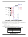
Freescale Semiconductor
Users Guide
MPC5121EQRUG
Rev. 6, 09/2010
MPC5121e Hardware Design Guide
This document is a collection of application examples
and practical information that relate to hardware design
issues for the MPC5121e and other microprocessors in
this family of devices. This document covers use of the
onboard DRAM controller, practical information on
Universal Serial Bus issues, and a description of the
method used to initially configure the microcontroller at
the release of reset.
Configuring the microcontroller for proper operation at
the release of reset is done by reading the external bus
while reset is released. This section explains how the
values read set up the initial memory map, the
configuration of the external memory bus and various
clock speeds.
The DRAM controller section explains how to set up the
timing of the high speed memory interface to the
Synchronous DRAM memory. Also, this section handles
the protocol between the SDRAM memory and the
microcontroller.
The USB section covers hardware issues related to
external physical interfaces, how the physical interfaces
are connected to the microprocessor, and PC board
layout issues related to USB signals.
In-depth material about using the MPC5121e is also
available in Freescale’s reference manual. See the
Freescale Web site: http://freescale.com
© Freescale Semiconductor, Inc., 2008–2010. All rights reserved.
Topic Reference
MPC5121e Hardware Design Guide. . . . . . . . . . . 1
MPC5121e Clocks . . . . . . . . . . . . . . . . . . . . . . . . 3
Understanding the Reset Configuration Word for the
MPC5121e . . . . . . . . . . . . . . . . . . . . . . . . . . . . . 25
MPC5121e DRAM Controller . . . . . . . . . . . . . . . 47
MPC5121E USB . . . . . . . . . . . . . . . . . . . . . . . . . 95
MPC5121e DIU Hardware Interface . . . . . . . . . 109
To provide the most up-to-date information, the revision of our documents on the World Wide Web will
be the most current. Your printed copy may be an earlier revision. To verify you have the latest information
available, refer to:
http://freescale.com
Revision History
Page
Number(s)
Date
Revision
Level
11/2008
0
Initial release.
N/A
12/2008
1
Added reset configuration word section.
N/A
02/2009
2
Added DRAM controller and USB sections.
N/A
03/2009
3
Updated DRAM controller section.
04/2009
4
Added DIU section.
06/2009
5
Added information about use of DRAM Controller Initialization Tool.
Corrected information in 2.5.2, “RST_CONF_PCIARB,” in same section.
09/2010
6
Corrected information in “Understanding the Reset Configuration Word for the
MPC5121e,” section 2.2, “Boot Interface Control,” about reset parameter
RST_CONF_ROMLOC.
Same changes in “Understanding the Reset Configuration Word for the
MPC5121e,” Appendix A: table 5, table 6, and table 7.
Description
63–64, 84–86
N/A
85–90
33
29
36, 37, 39
MPC5121e Hardware Design Guide, Rev. 6
2
Freescale Semiconductor
Freescale Semiconductor
User Guide
MPC5121e Clocks
by: Rakesh Chennamadhavuni
MSG Applications Engineering
This section discusses the clock structure, relationships
between various clocks, and how different module
clocks are derived on the MPC5121e.
1
Introduction
The wide range of applications supported by the
MPC5121e require a complex clocking structure with
different primary clock domains derived from four
separate oscillator sources. Internal PLLs and clock
dividers allow generation of a wide range of clock
references. Each peripheral clock may be individually
controlled; in other words, gated individually or scaled in
frequency to minimize total power consumption of the
device. The MPC5121e system requires a system-level
clock input: SYS_XTALI. This clock input may be
driven directly from an external oscillator or with a
crystal using the internal oscillator. The SYS_PLL is
programmed at reset by the reset configuration word
(RST_CONFIG) sampled at the rising edge
© Freescale Semiconductor, Inc., 2008. All rights reserved.
Contents
1
2
Introduction . . . . . . . . . . . . . . . . . . . . . . . . . . . . . . . . . . . 3
Initialization and Configuration . . . . . . . . . . . . . . . . . . . . 6
2.1 Reset Sequences . . . . . . . . . . . . . . . . . . . . . . . . . . 6
2.2 Enable/Disable Clock to Individual Modules . . . . . . 8
2.3 Changing the Frequency of the Clock . . . . . . . . . . . 8
3
Measurements. . . . . . . . . . . . . . . . . . . . . . . . . . . . . . . . . 9
4
PSC Clock Structure . . . . . . . . . . . . . . . . . . . . . . . . . . . 10
4.1 PSC in UART Mode. . . . . . . . . . . . . . . . . . . . . . . . 10
4.2 PSC in Codec Mode . . . . . . . . . . . . . . . . . . . . . . . 11
4.3 Introduction . . . . . . . . . . . . . . . . . . . . . . . . . . . . . . 11
4.4 Configuring and Observing PSC_MCLK_OUT . . . 12
5
PSC in AC97 Mode . . . . . . . . . . . . . . . . . . . . . . . . . . . . 14
6
PSC in SPI Mode. . . . . . . . . . . . . . . . . . . . . . . . . . . . . . 15
7
CAN Module Clock . . . . . . . . . . . . . . . . . . . . . . . . . . . . 15
8
General Clock and Power Circuitry Layout Guidelines . 17
8.1 Clock Circuitry . . . . . . . . . . . . . . . . . . . . . . . . . . . . 17
8.2 Power Circuitry . . . . . . . . . . . . . . . . . . . . . . . . . . . 17
8.3 Ferrite Beads in Filtering . . . . . . . . . . . . . . . . . . . . 19
Appendix A . . . . . . . . . . . . . . . . . . . . . . . . . . . . . . . . . . . . . . 20
A.1 Example Code for Pin Multiplexing of I/O Pads. . . 20
A.2 I/O Control Register Table for Clocks . . . . . . . . . . 20
A.3 Block Diagram of Various Clock Structures in
MPC5121e . . . . . . . . . . . . . . . . . . . . . . . . . . . . . . 22
Appendix B References . . . . . . . . . . . . . . . . . . . . . . . . . . . . . 23
Introduction
(de-assertion) of power-on reset. The SYS_PLL clock is then divided (SYS_DIV) and used as a reference
to the MPC5121e cores and peripherals.
The system oscillator may be disabled so that an externally generated clock may be used as a reference.
This can be performed by setting the RST_CONF_SYSOSCEN in the reset configuration word
(RST_CFG) at reset. There is a separate oscillator for the independent real-time clock (RTC) system. The
USB PHY contains its own oscillator with the input USB_XTALI and an embedded PLL. The SATA PHY
contains its own oscillator with the input SATA_XTALI and an embedded PLL.
The four oscillator sources are:
1. XTAL for system: This clock input may be driven directly from an external oscillator or with a
crystal using the internal oscillator. This is selected by RST_CONFIG_SYSOGEN in the reset
configuration word.
2. RTC oscillator clock: The RTC module contains circuitry on two clock and voltage domains. The
Vbat voltage domain circuitry operates from a 32.768 kHz oscillator input. The VCore domain or
programming interface operates from the IPS_CLK.
3. SATA oscillator clock: The SATA interface requires a 25 MHz crystal input that is independent of
the system oscillator. The 1.5 GHz clock required by the SATA physical interface is generated by
this 25 MHz input.
4. USB oscillator clock: The USB 2.0 specification requires a clock operating at up to 480 MHz. This
clock is derived from a dedicated oscillator input of 24 MHz and multiplied within the USB
physical interface for USB transmission. The USB-OTG controller operates from the IPS_CLK
interface.
— Note: A 24 MHz clock is used for internal PHY in this case. External PHYs may have a
different value.
MPC5121e Clocks, Rev. 0
4
Freescale Semiconductor
Introduction
XTALI
XTALO
SPMF[3:0]
1/2
DDR
Memory
Device
SDHC_DIV
sdhc_clk
SYS_CLK
SYS REF_CLK SYS SPLL_OUT SYS_DIV
PLL
OSC
SYSDIV[5:0]
RST_CONF_SYSOSCEN
DIU_DIV
diu_clk
csb_clk
1/2
CPMF[3:0]
Power
Architecture
PLL
ppc_clk
ips_clk
IPS_DIV
NFC_DIV
nfc_clk
LPC_DIV
lpc_clk
mbx_bus_clk
1/2
MBX_GPX_DIV
mbx_3d_clk
mbx_clk
pci_clk
PCI_DIV
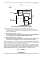
Figure 1. Diagram of Clock Structure
Below is a table of the modules connected to each individual clock.
Table 1. Clocks and Associated Modules
Module Reference Clock
Module(s)
CSB_CLK
AXE, CFM, CSBARB, DMA, MEM, PPC_PLL, PCI1,
PCI_DMA, PCI_IOS
IPS_CLK
BDLC, DIU1, EMB1, FEC, FIFOC, FUSE, GPIO, I2C, IPIC,
MSCAN1, PATA, PMC, RTC1, SAP1, SATA, SDHC, SPDIF,
TPM, USB0, USB1, WDT
LPC_CLK
EMB1, LPC
NFC_CLK
EMB1, NFC
PPC_CLK
E300
REF_CLK
MSCAN1, SYS_PLL
MBX_CLK
MBX
MBX_3D_CLK
MBX
MPC5121e Clocks, Rev. 0
Freescale Semiconductor
5
Initialization and Configuration
Table 1. Clocks and Associated Modules (continued)
Module Reference Clock
Module(s)
DDR_CLK
MDDRC, PRIMAN
PCI_CLK
PCI1
RTC_CLK
RTC
SATA_OSC
SATA_PHY
USB_OSC
USB_PHY
1
Indicates that the module has more than one reference clock.
2
Initialization and Configuration
2.1
Reset Sequences
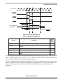
1. The PORESET will sample the reset configuration word.
2. The HRESET is qualified with respect to power-on reset after a certain number of clock cycles has
passed (see Table 2).
a) HRESET provides a mechanism to initialize all clocks and peripherals to the initial values.
b) This flow does not sample the reset configuration word.
3. SRESET provides a mechanism to shorten the boot flow by bypassing initialization of boot
peripherals and clocks.
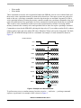
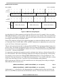
During the power-up sequence the PORESET pin must be asserted by an external device for a minimum
of 32 XTAL clock cycles. The oscillator input (XTALI) must be stable prior to PORESET de-assertion.
After PORESET has been qualified and released, the HRESET flow is started.
MPC5121e Clocks, Rev. 0
6
Freescale Semiconductor
Initialization and Configuration
XTAL CLOCK
PORESET
tHRVAL
HRESET
tsreset_delay
SRESET
tRST_CONF
tEXEC
RST_CONF[31:0]
ADDR[31:0]
Code execution starts 38 clocks
tRST_CONF_HOLD
after release of HRESET.
Figure 2. Power-On Reset Behavior
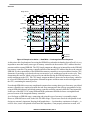
Table 2. Reset Option Clock Cycles
Symbol
Description
Value
(clock
cycles)
tHRVAL
Time HRESET is asserted after it has been qualified
tRST_CONF
Time reset configuration must be asserted prior to de-assertion of
PORESET
16
tRST_CONF_HOLD
Reset configuration hold time
4
tEXEC
Time between de-assertion and core execution
tSRESET_DELAY
Time delay between de-assertion of HRESET and the de-assertion of
SRESET
26800
TBD
16
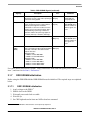
The default modules to which clocks should be enabled after reset are: CFG, LPC, NFC, TPR, PCI, DDR,
MEM, and MBX_BUS. The clocks CFG, LPC, NFC, DDR, and MEM should be enabled at all times for
correct operation. TPR must be set for all normal user modes.
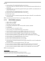
The reset configuration word controls the values (frequencies) of the default clocks after boot-up. Some
of the very important clock configuration fields that reset configuration word controls are mentioned in
Table 3. Refer also to the reset values of the SCFR1 and SCFR2 registers, to calculate the initial
frequencies.
MPC5121e Clocks, Rev. 0
Freescale Semiconductor
7
Initialization and Configuration
Table 3. Reset Configuration Word
Reset Parameter
Signal
Description
RST_CONFIG_COREPLL
EMB_AD[13:10]
Core PLL Multiply Factor
RST_CONFIG_SYSPLL
EMB_AD[26:23]
System PLL Multiply Factor
RST_CONFIG_SYSOGEN
EMB_AX02
Oscillator Bypass Mode
RST_CONFIG_SYSDIV
LPC_AX[3], EMB_AD[31:27]
System PLL Divider
RST_CONFIG_PCI66EN
EMB_AD[7]
Enable 66 MHz PCI Operation
See the Reset chapter in the MPC5121e reference manual for more information. Also see the Reset section
of this document (this section is in progress and will be added soon).
2.2
Enable/Disable Clock to Individual Modules
The clocks to some individual modules can be enabled or disabled. This can be done by either setting (for
enable) or clearing (for disable) the corresponding bit in the SCCR1 or SCCR2 register.
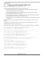
Example: If you want to disable the clock to the I2C module, then clear the bit I2C_EN in the SCCR2
register. If you want to enable the clock to the I2C module, then set the bit I2C_EN in SCCR2.
Example Code:
// Enable the I2C clock (this field is in SCCR2 register):
SET (I2C_EN) in IMMR+CLOCK_MODULE_BASE+SCCR2 i.e.
Write 1 in I2C_EN field at IMMR + 0x000_0F00+ 0x0000_0008.
// Disable the I2C clock.
CLEAR (I2C_EN) in IMMR+CLOCK_MODULE_BASE+SCCR2 i.e.
Write 0 in I2C_EN field at IMMR + 0x000_0F00+ 0x0000_0008.
NOTE
Disabling the clock to a module will only disable the clock to that module
— it does not have any effect on the clock itself. For the chip to operate
correctly some clocks have to be enabled at all times.
NOTE
SCCR1 and SCCR2 registers are in the Clocks module (refer to the
MPC5121e Reference manual).
2.3
Changing the Frequency of the Clock
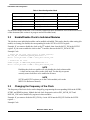
The frequency of the basic clocks can be changed by programming the corresponding fields in the SCFR1,
SCFR2, and SPMR registers. Module-derived clock frequencies such as PSC_MCLK_OUT and
MSCAN_CLK can be modified by registers in these modules.
Example: If you want to divide the IPS_CLK by 4 write 100’b into the IPS_DIV field in the SCFR1
register —
Example Code:
MPC5121e Clocks, Rev. 0
8
Freescale Semiconductor
Measurements
Write 4 (in IPS_DIV field) in IMMR+CLOCK_MODULE_BASE+SCFR1 i.e.
Write 4 in IPS_DIV field at IMMR + 0x0000_0F00+ 0x0000_000C.
Table 4. Register Fields and Associated Clocks
Register
Type
Input Clock
Output Clock
SPMR
SPMF
Multiplier
REF_CLK
SPLL_OUT
SPMR
CPMF
Multiplier
(SYS_CLK/2)
PPC_CLK
SCFR2
SYS_DIV
Divider
SPLL_OUT
SYS_CLK
SCFR1
IPS_DIV
Divider
(SYS_CLK/2)
IPS_CLK
SCFR1
PCI_DIV
Divider
(SYS_CLK/2)
PCI_CLK
SCFR1
MBX_GPX_DIV
Divider
MBX_BUS_CLK
MBX_(3D)_CLK
SCFR1
LPC_DIV
Divider
IPS_CLK
LPC_CLK
SCFR1
NFC_DIV
Divider
IPS_CLK
NFC_CLK
SCFR1
DIU_DIV
Divider
SYS_CLK
DIU_CLK
SCFR2
SDHC_DIV
Divider
SYS_CLK
SHDC_CLK
Divider
1
PSC_MCLK_OUT
Divider
1
CAN_SOURCE_CLK
PnCCR
PSCn_MCLK_DIV
MnCCR
1
3
Field
MSCANn_CLK_DIV
The input clock in this case depends on the multiplexer fields in those registers.
Measurements
Refer to the section “Understanding the Reset Configuration Word for the MPC5121e” in this document
for more information. This section has not yet been published.
NOTE
Special note on observing the PPC core clock: the internal PPC clock can be
brought out on one of the TPA pins.
Apart from the common pin muxing procedure, there is an additional step needed to bring the PPC clock
out. Depending on what you want to observe, set ECLK or SBCLK accordingly in HID0.
Table 5. Using HID0[ECLK] and HID0[SBCLK] to Configure CLK_OUT
HRESET
ECLK
SBCLK
CLK_OUT
Asserted
X
X
Bus clock (small pulse for every rising edge of SYSCLK)
Negated
0
0
Clock output off
0
1
Core clock divided by two
1
0
Core clock
1
1
Bus clock
HID0 is a special purpose register and can only be changed in supervisor mode via special instructions.
The clock_out_1 and clock_out_2 signals are further divided down before they go to the TPA pads. Refer
MPC5121e Clocks, Rev. 0
Freescale Semiconductor
9
PSC Clock Structure
to the TPA select table in appendix A. Refer to Freescale document MPCFPE32B, Programming
Environments Manual for 32-Bit Implementations of the PowerPC™ Architecture, for more information
about the special commands to be used.
A brief explanation of observing PSC_MCLK_OUT is mentioned in Section 4, “PSC Clock Structure.”
4
PSC Clock Structure
4.1
PSC in UART Mode
The transmit and receive baud rate for the PSC in UART mode can be generated from either the internal
or external clock.
• The source of the internal clock is IPS_CLK.
• The source of the external clock is PSC_MCLK_IN.
Both clocks are divided by the prescaler. In addition, the ips_clk is further divided by the 16-bit
timer/counter. As shown in Figure 3 the ips_clk is divided by the timer/counter and then by a prescaler of
16 or 10, whereas the PSC_MCLK_IN is divided only by a prescaler of 10. Transmit and receive clocks
are independent of each other. The transmit clock is independent from the receive clock and vice versa. In
other words, you can choose the internal clock for the transmitter and the external clock for the receiver.
The clock source and prescaler for both transmitter and receiver are selected by setting the appropriate bits
in the RCS and TCS fields in the Clock Select Register (CSR) in the PSC module.
TxD
PSC
Sample Rate Selection for TX and CSR registers
Clock Source Selection for CSR register
Tx Buffer
16-Bit
Divider
{CTUR:CTLR}
Tx Sample Rate 16 or 10
IPS Clock
PSC_MCLK_IN
Rx Sample Rate 16 or 10
Clock Source Selection for CSR register
RxD
Rx Buffer
Sample Rate Selection for RX and CSR registers
Figure 3. Clocking Source for PSC in UART Mode
The baud rate depends on the CSR register and the CTR register. The baud rate of the TX signal is
calculated as follows:
Table 6. TCS Baud Rate Calculation
Transmit Clock Select
Baud Rate
0000–1101
ips_clk / (16 CT[0:15])
1111
ips_clk / (10CT[0:15])
1110
psc_mclk_in / 10
MPC5121e Clocks, Rev. 0
10
Freescale Semiconductor
PSC Clock Structure
Table 7. RCS Baud Rate Calculation
Receive Clock Select
Baud Rate
0000–1101
ips_clk / (16 CT[0:15])
1111
ips_clk / (10 CT[0:15])
1110
psc_mclk_in / 10
NOTE
Transmit clock and receive clock are independent of each other. CSR,
CTUR and CTLR registers are in the PSC module (refer to the MPC5121e
reference manual).
4.2
PSC in Codec Mode
PSC in codec mode uses PSC_MCLK_OUT. A brief introduction to PSC_MCLK_OUT is given below.
MCLK_SRC
MCLK_EN
XCLK
MCLK_DIV_OUT
REF_CLK
PSC_MCLK_IN
Power
Gate
mclk_div
SPDIF_RXCLK
SPDIF_TXCLK
PSC_MCLK_OUT
MCLK_1_SRC
MCLK_0_SRC
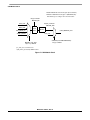
Figure 4. Generation of PSC_MCLK_OUT
4.3
Introduction
The PSC_MCLK_OUT can be generated from five clock sources. The generation of the clocks is divided
into two stages.
1. First is the divider stage, where one of four clock sources is selected by the MCLK_0_SRC field
in PnCCR. Then this clock is further divided by the divider, if that clock is enabled by MCLK_EN.
If MCLK_EN has been cleared, then the clock is disabled and the input clock source will not reach
the divider.
2. In the second stage either the divided clock source or spdif_rxclk can be selected as the final
PSC_MCLK_OUT, depending on the value of MCLK_1_SRC. SPDIF_RXCLK bypasses the
divider.
SPDIF_TXCLK and PSC_MCLK_IN are external clocks and SPDIF_RXCLK is generated by the SPDIF
module. External clocks should be provided if these are used as clock sources for generation of
PSC_MCLK_OUT. External clock sources can be provided from the appropriate pads. Pin muxing for the
pads should be done so that these clocks can reach internally into the chip. See appendix A for pin muxing
details about SPDIF_TXCLK and PSC_MCLK_IN, and example code for pin muxing.
MPC5121e Clocks, Rev. 0
Freescale Semiconductor
11
PSC Clock Structure
4.4
Configuring and Observing PSC_MCLK_OUT
Below is the simplest procedure to observe PSC_MCLK_OUT.
Configuring and observing PSC_MCLK_OUT is a seven step process:
1. Select the proper clock source by configuring MCLK_0_SRC field in the PnCCR register.
2. Clear the MCLK_EN field in the PnCCR register.
3. Write the appropriate divide value into the PSC_MCLK_DIV field in the PnCCR register.
4. Set the MCLK_EN field in the PnCCR register.
5. Choose the proper clock source by configuring the MCLK_1_SRC field in the PnCCR register.
6. Write 0x0100 8100 to the SICR register in the PSCn module.
7. Perform pin muxing for signal 4 in the selected PSC. Now the PSC_MCLK_OUT can be observed
at pin PSCn_4.
Refer to appendix A for pin muxing details. In the above case it is assumed that all clock sources are
provided.
Example code for PSC0 (this is a simple way of observing the clock; depending on the mode of
implementation, there may be several other ways):
Assumptions in this example: Using SYS_CLK in the first stage and MCLK_DIV in the second stage.
// Pin muxing (selecting function) psc0_4 from PSC0_4 I/O Pad.
Write 0 in FuncMux field in IMMR+IOCTL_BASE_ADDRESS+I0CTL_PSC0_4 i.e
Write 0 in FuncMux field in IMMR+0x0A000+0x0304.
// Select one from four clock sources in first stage. (Here sys_clk is used)
Write 0 in MCLK_0_SRC in IMMR+CLOCKS_MODULE_ADDRESS+P0CCR i.e.
Write 0 in MCLK_0_SRC field at IMMR+0x0000_0F00+0X0000_001C.
// The divider value should be changed after disabling the mclk_en
Clear (MCLK_0_EN) in IMMR+CLOCKS_MODULE_ADDRESS+P0CCR i.e.
Write 0 in MCLK_0_EN field at IMMR+0x0000_0F00+0X0000_001C.
// Changing the divider value
Write (divider value in PSC0_MCLK_DIV field) in IMMR+CLOCKS_MODULE_ADDRESS+P0CCR i.e.
Write (divider value in PSC0_MCLK_DIV) at IMMR+0x0000_0F00+0X0000_001C.
// Enabling the mclk_en
SET(MCLK_0_EN) in IMMR+CLOCKS_MODULE_ADDRESS+P0CCR i.e.
Write 1 in MCLK_0_EN field at IMMR+0x0000_0F00+0X0000_001C.
// Select one from two clock sources in second stage.
Write 0 in MCLK_1_SRC in IMMR+CLOCKS_MODULE_ADDRESS+P0CCR i.e.
Write 0 in MCLK_1_SRC field at IMMR+0x0000_0F00+0X0000_001C.
// Perform this operation.
Write 0x01008100 into IMMR+ PSC0_BASE_ADDRESS+ PSC_SICR i.e.
Write 0x0100_8100 into IMMR+ 0x0001_1000+0x0000_0040.
MPC5121e Clocks, Rev. 0
12
Freescale Semiconductor
PSC Clock Structure
NOTE
PnCCR registers are in the Clocks module (refer to the MPC5121e reference
manual).
MCLK
PSC
PSC_MCLK_OUT
Clock
Generation
Unit
BCLK
FrameSync
BCLKDiv[0:15]+1
RxD
External
Interface
Signals
Receiver
Interface to
the FIFOC
Transmitter
TxD
PSC Codec Block Diagram
Figure 5. Block Diagram and Signal Definition for Codec Mode
Depending on the value of the GENCLK field in the SICR register in the PSC module:
• The serial BCLK and the FrameSync can be inputs that come from an external codec device.
• They can be internally generated by the PSC and provided as outputs to the external device, under
control of bit SICR[GenClk].
If the bit GenClk in the SICR register is set to zero:
• The BCLK and the FrameSync are inputs. In this case the FrameSync width can be anything from
one BCLK period up to the total FrameSync length/period minus one BCLK.
If the bit GenClk in the SICR register is set to one:
• If the GenClk bit is set to one, the PSC generates the BCLK and the FrameSync signal. The source
for the internal clock generation is the PSC_MCLK_OUT provided by the clock module.
The PSC provides the MCLK_OUT clock to the external codec divided independently, no matter whether
the PSC is configured as a master (provide BCLK and FrameSync) or as a slave (receive the clock signals).
Therefore there is no need for an external crystal for the external device.
Each PSC consists of a CCR register to generate a BCLK and a FrameSync signal. If the PSC is configured
as a master and MCLK is available, the PSC generates both clock signals, independent of whether the
transmitter or receiver is enabled or not. If the PSC is configured as SPI master mode, the BCLK is only
generated if the transmitter and receiver are enabled and TX data is available in the TX FIFO.
MCLK
BCLK = --------------------------------------------------BCLKDiv 0:15 + 1
MPC5121e Clocks, Rev. 0
Freescale Semiconductor
13
PSC in AC97 Mode
FrameSync Length = Frame SyncDiv[0:7]+1
When the FrameSync is an output, the CTUR register can program the pulse width. This register defines
the number of BCLK cycles while the FrameSync signal is active. The default reset value for this register
is 0x00. Therefore, the default FrameSync width is one BCLK.
Frame sync width = CTUR[0:7] + 1
NOTE
FrameSync width CTUR: Defines the number of BCLK while the
FrameSync is active.
FrameSync length CCR[FrameSyncDiv]: Defines the number of BCLK
until the next frame starts.
5
PSC in AC97 Mode
PSC
BCLK
Clock
Generation
Unit
Sync
Sdata_in
Receiver
External
Interface
Signals
Interface to
the FIFOC
Sdata_out
Transmitter
Reset
Logic
Reset
Figure 6. PSC AC97 Block Diagram
The PSC receives the BCLK from the external AC97 codec and provides the associated frame signal. In
AC97 mode, the clock and frame relations are fixed.
• The BCLK is an input from the external codec.
• The PSC divides BCLK by 256 to generate a frame pulse (Sync) that is high for 16 BCLK cycles.
Therefore, the CCR register and the SICR[GenClk] bit are not used.
MPC5121e Clocks, Rev. 0
14
Freescale Semiconductor
PSC in SPI Mode
6
PSC in SPI Mode
In SPI master mode:
• The BCLK (SCLK) frequency is generated by dividing down the MCLK frequency.
• The DSCLK defines the delay between the SS going active and the first BCLK (SCK) clock pulse
transition. The DSCLK delay is created by dividing down the MCLK frequency. The delay
between consecutive transfers is created by dividing down the IPS_CLK clock frequency.
• DTL stands for length of delay after transfer. The counter/timer determines the length of time the
PSC delays after each serial transfer (the length of time that SS stays high/inactive between
consecutive transfers).
Delay after transfer can be used to ensure that the deselect time requirement is met (for peripherals that
have such a requirement). Some peripherals must be deselected for a minimum period of time between
consecutive serial transfers.
CCR[0:7] + 1
DSCKL Delay = --------------------------------MCLK
CT[0:15] + 2
3
DTL = -------------------------------------------------- + -----------------------------------------IPS_CLK Frequency MCLKFrequency
where CT[0:7] = CTUR[0:7]
CT[8:15] = CTLR[0:7]
7
CAN Module Clock
The CAN_SOURCE_CLK can be generated from five clock sources. The generation of the clocks is
divided into two stages.
1. The first stage is the divider stage, where one of four clock sources is selected by the
MSCAN_CLK_SRC field from the MnCCR register. Then this clock is further divided by the
divider, as long as that clock is enabled by MSCAN_EN. If the clock is disabled by clearing
MSCAN_EN then the input clock source will not reach the divider.
2. In the second stage either the divided clock source or IPS_CLK can be selected as the final
CAN_SOURCE_CLOCK based on the CLKSRC bit in the CANCTL1 register in the MSCAN
module. IPS_CLK bypasses the divider.
SPDIF_TXCLK and PSC_MCLK_IN are external clocks. External clocks should be provided if these are
used as clock sources for the generation of PSC_MCLK_OUT. External clock sources can be provided
from the appropriate pads. Pin muxing for the pads should be done so that these clocks can reach internally
into the chip. Refer to Section 4, “PSC Clock Structure,” for example code for pin muxing
PSC_MCLK_IN and SPDIF_CLK.
NOTE
The MnCCR register is in the clock module while the CANCTL1 register is
in the MSCAN module.
MPC5121e Clocks, Rev. 0
Freescale Semiconductor
15
CAN Module Clock
MnCCR: MSCAN Clock Control Register (Clocks Module)
CANCTL1: MSCAN Control Register 1 (MSCAN Module)
Bit numbering is according to the Power PC notation.
Bit[15] in MnCCR
MSCAN_EN
Bit[0:14] in MnCCR
SYS_CLK
MSCAN_SRC
REF_CLK
Clock
Gate
PSC_MCLK_IN
Divider
CAN_SOURCE_CLK
IPS_CLK
SPDIF_TXCLK
CLKSRC (From MSCAN Module)
MSCAN_CLK_SRC
Bit[1] in CANCTL1
Bit[16:17] in MnCCR
psc_mclk_in is an external clock.
spdif_txclk is generated by SPDIF module.
Figure 7. CAN Module Clock
MPC5121e Clocks, Rev. 0
16
Freescale Semiconductor
General Clock and Power Circuitry Layout Guidelines
8
General Clock and Power Circuitry Layout Guidelines
8.1
Clock Circuitry
•
•
•
•
•
•
8.2
The crystal oscillator is sensitive to noise from other signals and also to stray capacitances. In order
to reduce the coupling between the clock traces and other high speed traces, and therefore decrease
the crosstalk, it is recommended to keep the crystal oscillator away from signals with fast rise
and/or fall times (< 3 ns). A separation of at least three times the trace width (five times is better)
will in most cases keep the crosstalk to acceptable levels.
In order to decrease the effect of the resonant current that flows in the circuit, the IC pins, load
capacitor, crystal, and resistors should be placed close to each other, so that a smaller loop area is
achieved.
In order to minimize the board skew and achieve a reliable timing, it is recommended to use a
single routing plane to route the clock traces. This routing plane must be adjacent to a solid
reference plane.
Every via has parasitic capacitance and inductance associated with it which degrades the signal
quality due to impedance discontinuities and signal reflections. Usually it is the series parasitic
inductance that creates the most problems. This also affects the rising edge of the signals. Therefore
vias should be avoided on clock traces.
The preferred characteristics of the load capacitor are low leakage, low effective series resistance
(ESR), and stability across temperature.
To minimize the radiations it is usually a good practice not to route traces near the edges of the
PCB. Also, as a trace approaches the edge of a reference plane the impedance changes — this will
impact signal integrity.
Power Circuitry
The power supply noise, if not properly controlled, causes unpredictable behavior in the circuit. The
common method used to suppress this noise is to use a capacitor near each load (IC), providing a low
impedance path to ground. Use of power and ground planes will greatly reduce the impedance of the power
nets.
Also, a large bypass capacitor is usually placed in parallel to the power supply. In this way the problem of
wiring inductance of supply traces at higher frequencies can to a certain extent be overcome. This capacitor
provides a low impedance path between power and ground. But it should be noted that the capacitors are
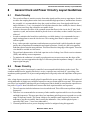
not perfect. Figure 8 shows the difference between the ideal capacitor and the real capacitor.
1. The real capacitor includes inductance in series on both ends. This will become a problem at higher
frequencies.
2. Therefore it is recommended to use an array of other smaller capacitors which cover low, medium,
and high frequencies. This array provides a low impedance path from power to ground over a wide
range of frequency bands. (The reason it helps to use multiple small capacitors is because the
inductances are then in parallel, thus lowering the inductance. Also, smaller physical parts —
especially SMT parts — have lower inductance.)
3. Common problems such as power drooping can also be mitigated using this approach.
MPC5121e Clocks, Rev. 0
Freescale Semiconductor
17
General Clock and Power Circuitry Layout Guidelines
4. The bypass capacitors must be placed close to the chip, so that the overall loop area is less. This
will decrease the series inductance that the signal sees and also decrease the EMI.
5. If possible use shorter and wider traces for traces from VCC and GND. This will decrease the series
inductance. (It is better to use planes.)
6. Common characteristics like low ESR should be considered while choosing the bypass capacitors.
(It is necessary to be aware of ESR on larger capacitors as most MLC bypass capacitors already
have low ESR.) Some of the factors that should be considered while calculating the value of the
bypass capacitors are:
— Maximum step change in the supply current
— Maximum noise that can be tolerated
— Maximum common path impedance
— Series inductance of the supply trace
Ideal Capacitor
Real Capacitor
Figure 8. Ideal and Real Capacitors
Power
Supply
Loop Area
Power
Supply
Decoupling
Capacitor
Loop
Area
Figure 9. Loop Area
MPC5121e Clocks, Rev. 0
18
Freescale Semiconductor
General Clock and Power Circuitry Layout Guidelines
Ferrite Bead
Power
Supply
Circuitry
C1
C2
C3
Component
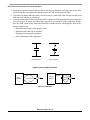
Figure 10. Circuit with Series of Arrays
Usually a combination of ferrite beads and capacitors provides ideal filtering on supply lines.
8.3
Ferrite Beads in Filtering
Ferrite beads are used to suppress high frequency noise in electronic circuits. The fundamental mechanism
behind this is that beads provide very low impedance at DC and relatively high impedance over a range of
frequencies (which is dependent on physical characteristics).
The beads are passive components, and it should be noted that the beads don’t enhance the signal quality
by themselves but will suppress and isolate the noise, as well as decrease the EMI radiation. The magnetic
field is contained within the beads and they cannot be detuned by external magnetic fields.
The characteristics of beads that determine their properties are:
• The frequency range that can be effectively suppressed — this is determined by the type of ferrite
material used.
• The level of attenuation — this is determined by the physical size and shape of the bead.
Usually the impedance is directly proportional to the length of the ferrite beads.
The effectiveness of the bead deteriorates rapidly once it crosses the Curie temperature. This temperature
depends on the material and may vary from 120 C to 500 C.
MPC5121e Clocks, Rev. 0
Freescale Semiconductor
19
General Clock and Power Circuitry Layout Guidelines
Appendix A
A.1
Example Code for Pin Multiplexing of I/O Pads
1. Select the desired signal.
2. Look up the pad I/O control register table in the manual and select the required pad.
— It should be noted that some signals are multiplexed to multiple pads. Therefore the required
pad must be carefully selected.
— Pads belong to certain categories which determine the variables that can be controlled and thus
their properties. All the pads contain FUNCMUX and slew rate select fields as basic fields.
3. Write the binary value of the desired signal in the FUNCMUX field in the chosen pad register.
Which individual fields in the pad are to be selected depends on the implementation that is being used.
It is recommended to use the maximum slew rate possible to ensure a good signal.
Example Code:
1. PSC_MCLK_IN is the desired signal for which pin multiplexing is done.
2. Looking into the I/O control register table it is observed that this signal is multiplexed in
— NFC_CE0 pad
— PSC_MCLK_IN pad
3. NFC_CE0 pad is chosen for pin multiplexing in this example.
4. Write 01 in FUNCMUX field in IMMR+IOCTL_BASE_ADDRESS+ IOCTL_NFC_CE0.
5. Write 01 in FUNCMUX field in IMMR+0x0A000+0X01C.
Other fields in this register are chosen depending on the specific application.
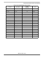
A.2
I/O Control Register Table for Clocks
Note: This is only a subset of the entire table. Please refer to the MPC5121e reference manual (chapter I/O
control) for the entire table. The Type column in the following table shows the type of the pad register.
Each register type has its own configurable parameters. FuncMux and slew rate1 are common to all the
register types. Refer to the manual for more information on the configurable parameters, their definitions,
and their values.
Table 8. Pin I/O Control Register Table for Clocks
Pin Name
Signal Name
FuncMux
(FieldValue)
Type
LPC_CLK
LPC_CLK
00
STD
PATA_IOR_B
SDHC_CLK
01
STD
NFC_WP_B
SDHC_CLK
01
STD
PSC8_4
SDHC_CLK
01
STD
1.The number of bits for this field differs by register type.
MPC5121e Clocks, Rev. 0
20
Freescale Semiconductor
General Clock and Power Circuitry Layout Guidelines
Table 8. Pin I/O Control Register Table for Clocks
Pin Name
Signal Name
FuncMux
(FieldValue)
Type
PSC3_4
VIU_PIX_CLK
10
STD
I2C0_SCL
I2C0_SCL
00
STD_ST
I2C1_SCL
I2C1_SCL
00
STD_ST
I2C2_SCL
I2C2_SCL
00
STD_ST
SPDIF_TXCLK
SPDIF_TXCLK
00
STD_ST
IRQ1
SPDIF_TXCLK
01
STD_ST
PSC_MCLK_IN
PSC_MCLK_IN
00
STD_ST
PSC0_2
FEC_TX_CLK
01
STD_ST
PSC2_4
FEC_RXCLK
01
STD_ST
PSC2_0
USB0_CLK
10
STD_ST
PSC5_0
USB1_CLK
01
STD_ST
PSC6_0
DIU_CLK
10
STD_ST
NFC_CE0_B
PSC_MCLK_IN
10
STD_PU_ST
LPC_CS1_B
SPDIF_TXCLK
01
STD_PU_ST
PCI_AD07
FEC_TX_CLK
10
PCI
PCI_AD04
VIU_PIX_CLK
01
PCI
PCI_CLK
PCI_CLK
00
PCI
PCI_AD31
USB0_CLK
01
PCI_ST
PCI_AD19
USB1_CLK
10
PCI_ST
PCI_AD09
FEC_RX_CLK
10
PCI_ST
CKSTP_OUT_B
TPA
01
STD
LPC_CLK
TPA
01
STD
MPC5121e Clocks, Rev. 0
Freescale Semiconductor
21
General Clock and Power Circuitry Layout Guidelines
A.3
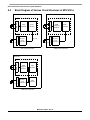
Block Diagram of Various Clock Structures in MPC5121e
MPC5121e
MPC5121e
Vcore
Domain
ips_clk
System
Clock
Generation
SATA Osc
Vbat
Domain
SATA Subsystem
Sys Osc
Sys Osc
RTC Osc
RTC Module
SATA
Physical
Interface
SATA
Controller
System
Clock
Generation
SATA Clock Generation
RTC Clock Generation
MPC5121e
USB Osc
USB
Physical
Interface
USB
Controller
Sys Osc
USB Subsystem
System
Clock
Generation
USB
Controller
USB Clock Generation
MPC5121e Clocks, Rev. 0
22
Freescale Semiconductor
General Clock and Power Circuitry Layout Guidelines
Appendix B References
MPC5121e Reference Manual Rev. 3, MPC5121ERM, Freescale Semiconductor, 2008.
High-Speed Digital Design: A Handbook of Black Magic, Howard W. Johnson and Martin Graham,
Prentice Hall, 1993.
“Effects of Plane Splits on High-Speed Signals,” Dr. Abe Riazi, Printed Circuit Design & Fab.
http://pcdandf.com/cms/content/view/3413/95/
“High Speed PCB Design,” Jack Horgan, EDAcafe.
http://www10.edacafe.com/nbc/articles/view_weekly.php?section=Magazine&articleid=209218
MPC5121e Clocks, Rev. 0
Freescale Semiconductor
23
THIS PAGE IS INTENTIONALLY BLANK
MPC5121e Clocks, Rev. 0
24
Freescale Semiconductor
Freescale Semiconductor
User Guide
Understanding the Reset Configuration
Word for the MPC5121e
by: Mark Ruthenbeck
Microcontroller System Group
1
Introduction
The MPC5121e supports a multitude of boot options,
such as what interface to fetch the boot code from, at
what speeds the system PLL will run, etc. In this section
of this quick reference user guide we will discuss and
describe the reset configuration word on the
MPC5121e/5123.
1.1
Abstract
This document describes the functions and clarifies the
reset configuration selections for the MPC5121e/5123.
2
Detailed Description
The reset configuration word consists of signals inputted
on the EMB bus from EMB[31..0] and the EMB AX
AX[3].
The RST_CONF word is latched when the PORESET
becomes qualified. This controls the boot configuration
© Freescale Semiconductor, Inc., 2008–2010. All rights reserved.
Contents
1
Introduction . . . . . . . . . . . . . . . . . . . . . . . . . . . . . . . . . .
1.1 Abstract . . . . . . . . . . . . . . . . . . . . . . . . . . . . . . . . .
2
Detailed Description . . . . . . . . . . . . . . . . . . . . . . . . . . .
2.1 Clocking Modes and Speeds. . . . . . . . . . . . . . . . .
2.2 Boot Interface Control . . . . . . . . . . . . . . . . . . . . . .
2.3 NOR Flash Configurations. . . . . . . . . . . . . . . . . . .
2.4 NAND Flash Configurations . . . . . . . . . . . . . . . . .
2.5 PCI Bus Configuration . . . . . . . . . . . . . . . . . . . . . .
2.6 Other System Functions . . . . . . . . . . . . . . . . . . . .
3
References . . . . . . . . . . . . . . . . . . . . . . . . . . . . . . . . . .
4
Revision History. . . . . . . . . . . . . . . . . . . . . . . . . . . . . . .
Appendix A Reset Configuration Word Tables . . . . . . . . . . .
Appendix B Non-Mux Mode Addressing Pin Assignment . . .
Appendix C Mux Mode Addressing Pin Assignments . . . . . .
Appendix D NAND Flash Pin Connections . . . . . . . . . . . . . .
25
25
25
26
29
30
32
33
33
35
35
36
41
43
46
of the device. Each RST_CONF pin must be driven appropriately to ensure that the device enters the
desired mode of operation. The value latched into the device at reset may be verified by access to the
RCWLR and RCWHR registers (IMMRBAR+ 0x0e00, IMMRBAR + 0x0e04).
These configuration inputs control the way the system behaves beginning at boot time. These items
include:
1. Clocking modes and clock speeds
2. Boot configurations — in other words, what interface to boot from, how the boot is to be handled,
what address to boot from, etc.
3. Flash configurations for both NOR and NAND flash
4. PCI bus configuration
5. Miscellaneous items such as test modes, little endian modes, etc.
2.1
Clocking Modes and Speeds
Table 1. Clocking Reset Configuration
Reset Parameter
Signal
Description
RST_CONF_SYSOSCEN
EMB_AX02
Oscillator bypass mode
0 System Oscillator bypass mode
1 System Oscillator mode
RST_CONF_SYSPLL
EMB_AD[26:23]
System PLL multiply factor
See, “MPC5121e Clocks,” for programming options.
RST_CONF_SYSDIV
LPC_AX[3],
EMB_AD[31:27]
System PLL divider
See, “MPC5121e Clocks,” for programming options.
RST_CONF_COREPLL
EMB_AD[13:10]
Core PLL multiply factor
See, “MPC5121e Clocks,” for programming options.
2.1.1
RST_CONF_SYSOSEN
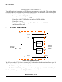
Starting from the clock source, the RST_CONF_SYSOSCEN bit tells the chip if the oscillator is to be used
or not. If the system is being driven from an external oscillator and not a crystal, then this bit needs to be
set to 0. If the system is being driven by a crystal, then this bit must be set to 1 (enabling the oscillator).
2.1.2
RST_CONF_SYSPLL/SYS_CONV_SYSDIV
The RST_CONF_SYSPLL bit sets up the PLL multiplier, and then the RST_CONF_SYSDIV divides the
PLL output. This output becomes the SYS_CLK. The maximum clock speed for SYS_CLK is 400 MHz.
Understanding the Reset Configuration Word for the MPC5121e, Rev. 1
26
Freescale Semiconductor
Sys
Osc
Sys
Osc
REF_CLK
RST_CONF_SYSOSCEN
SPLL_OUT
SPMF[3:0]
RST_CONF_SYSPLL
SYS_DIV
SYS_CLK
SYS_DIV[5:0]
RST_CONF_SYSDIV
Figure 1. System Clocking
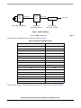
fSPLL = SPMF fREF_CLK
Eqn. 1
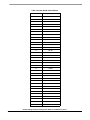
The system PLL multiplier factor values are shown in Table 2.
Table 2. System PLL Multiplier Factor
System PLL Multiplier Factor (SPMF)
SPMF Value[3:0]
Bypass mode — used for testing
0001
12
0010
16
0011
20
0100
24
0101
28
0110
32
0111
36
1000
40
1001
44
1010
48
1011
52
1100
56
1101
60
1110
64
1111
68
0000
The SYS_CLK output is finally determined by the SYS_DIV factor, as shown in Table 3.
Understanding the Reset Configuration Word for the MPC5121e, Rev. 1
Freescale Semiconductor
27
Table 3. System Divide Values/Factors
Divide Factor
SYS_DIV[5:0] Value
2
000000
2.5
000001
3
000010
3.5
000011
4
000100
4.5
000101
5
000110
6
001000
7
000111
8
001001
9
001010
10
001100
11
001011
12
001101
13
001110
14
010000
15
001111
16
010001
17
010010
18
010100
19
010011
20
010101
21
010110
22
011000
23
010111
24
011001
25
011010
26
011100
27
011011
28
011101
29
011110
30
100000
31
0111111
32
100001
33
100010
Understanding the Reset Configuration Word for the MPC5121e, Rev. 1
28
Freescale Semiconductor
All other settings are reserved.
The SYS_CLK or system clock is used as the primary clock source for the rest of the chip. This clock
cannot exceed 400 MHz. The equation for this is:
SYS_CLK = (SPMF fREF_CLK)/(Divide Factor)
2.2
Eqn. 2
Boot Interface Control
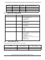
Reset Parameter
Signal
Description
RST_CONF_ROMLOC
EMB_AD[1:0]
Selects boot device
00 LPC boot
01 NAND (NFC) boot
10 Reserved
11 NAND (NFC) boot see also definition of ST_CONF_NFC_PS
RST_CONF_BMS
EMB_AD[5]
Boot mode select
Selects e300 boot vector and configures default value for LPC CS0 or
NFC base address.
Setting these configuration bits selects which interface the system uses for the boot code. See Section 2.4,
“NAND Flash Configurations,” for details about other bits that configure the balance of the interface.
2.2.1
RST_CONF_ROMLOC
These configuration bits select the boot device. The choices are simply between the LPC (NOR flash) or
NAND flash. These bits, in conjunction with RST_CONF_NFC_PS, also help define the type of NAND
flash.
When these bits are set for LPC, the MPC5121e selects the device that is on CS0 (chip select 0) during
boot mode. Otherwise the boot sequence will be done via the NAND flash device.
Reset Parameter
Signal
RST_CONF_ROMLOC
EMB_AD[1:0]
2.2.2
Description
Selects boot device
00 LPC boot
01 NAND (NFC) boot
10 Reserved
11 NAND (NFC) boot — see also definition of ST_CONF_NFC_PS
RST_CONF_BMS
Reset Parameter
RST_CONF_BMS
Signal
EMB_AD[5]
Description
Boot mode select
Selects e300 boot vector and configures default value for LPC CS0 or
NFC base address.
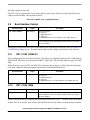
This bit is the boot mode select (BMS) pin and defines the boot mode vector — in other words, the memory
location for CS0 or for NFC base address. See the table below for the choices of boot memory locations.
Understanding the Reset Configuration Word for the MPC5121e, Rev. 1
Freescale Semiconductor
29
Boot Device
Boot Mode Select
Definition
Boot Start Address/Boot Vector
LPC (CS0)
0
Boot low
0x00000000/0x00000100
LPC (CS0)
1
Boot high
0xFFF00000/0xFFF00100
NAND
0
Boot low
0x00000000
NAND
1
Boot high
0xFFF00000
2.3
NOR Flash Configurations
Reset Parameter
Signal
Description
RST_CONF_LPC_AX
EMB_AD[9:8]
LPC address extension mode
00 No LPC Address Extension
01 Use LPC_AX[pata]
10 Use LPC_AX[nfc]
11 Reserved
RST_CONF_LPC_MX
EMB_AD[16]
LPC mux mode configuration
0 Non-multiplexed mode
1 Multiplexed mode
RST_CONF_LPC_WA
EMB_AD[17]
LPC word/byte addressing
0 Byte addressing
1 Word addressing
RST_CONF_LPC_DBW
EMB_AD[19:18]
LPC data port size
00 8-bit
10 Reserved
01 16-bit
11 32-bit
RST_CONF_NFC_PS
EMB_AD[20]
NAND flash page size
if RST_CONF_ROMLOC = 01 then RST_CONF_NFC_PS
defines the page size:
0 512-byte page size
1 2 KB page size
if RST_CONF_ROMLOC = 11 then
RST_CONF_NFC_PS defines the spare size with a fixed
page size of 4K:
0 64 bytes spare size
1 218 bytes spare size
2.3.1
RST_CONF_LPC_AX
This bit defines which set of pins have the LPC_AX[] signals.
LPC_AX[]
Ball Number
RST_LPC_AX [01]
Ball/Pin Number
RST_LPC_AX [10]
LPC_AX04
H2
G2
LPC_AX05
J4
G3
Understanding the Reset Configuration Word for the MPC5121e, Rev. 1
30
Freescale Semiconductor
LPC_AX[]
Ball Number
RST_LPC_AX [01]
Ball/Pin Number
RST_LPC_AX [10]
LPC_AX06
J3
H5
LPC_AX07
J2
H4
LPC_AX08
K5
H1
LPC_AX09
NA
G4
When using the non-mux mode addressing, these bits are required to be set. See Section Appendix B,
“Non-Mux Mode Addressing Pin Assignment,” for details on the pin/signal assignments for non-mux
mode addressing.
2.3.2
RST_CONF_MX
This bit defines the local plus (CS0) address/data mode. The choices are multiplexed (mux) or
non-multiplexed. For the multiplexed addressing mode there is an address tenure, followed by an ALE,
then the data tenure. For non-multiplexed mode, the address and data tenure are concurrent. The
non-multiplexed mode is, in general, a faster method of accessing data in the flash.
Refer to Section Appendix B, “Non-Mux Mode Addressing Pin Assignment,” and Section Appendix C,
“Mux Mode Addressing Pin Assignments,” for package pin assignments for these two modes.
Reset Parameter
RST_CONF_LPC_MX
2.3.3
Signal
EMB_AD[16]
Description
LPC mux mode configuration
0 Non-multiplexed mode
1 Multiplexed mode
RST_CONF_DBW
This bit selects whether the local plus bus controller is in word or byte addressing mode.
Reset Parameter
RST_CONF_LPC_WA
Signal
EMB_AD[17]
Description
LPC word/byte addressing
0 Byte addressing
1 Word addressing
Byte addressing uses the lowest significant address line as A0 from the MPC5121e. If the system is set up
for 16-bit data bus, then A0 is a no connect. A1 from the MPC5121e would be connected to A0 of the
memory (or peripheral) device. In word addressing mode, internal to the MPC5121e, the address lines are
shifted and A0 would then be connected to A0 of the memory (or peripheral) device.
2.3.4
RST_CONF_DPW
These sets of bits select the data port width (DPW) for the LPC (CS0) during boot. This is applicable for
both mux and non-mux addressing modes.
Understanding the Reset Configuration Word for the MPC5121e, Rev. 1
Freescale Semiconductor
31
Reset Parameter
RST_CONF_LPC_DBW
Signal
EMB_AD[19:18]
Description
LPC data port size
00 8-bit
10 Reserved
01 16-bit
11 32-bit
See Section Appendix B, “Non-Mux Mode Addressing Pin Assignment,” for details on the pin/signal
assignments for non-mux mode addressing and Section Appendix C, “Mux Mode Addressing Pin
Assignments,” for details on the pin/signal assignments for mux mode.
2.4
2.4.1
NAND Flash Configurations
RST_CONF_NFC_PS
These sets of bits select the NAND flash page size (NFC_PS) and, in conjunction with
RST_CONF_ROMLOC, the 4K page size and spare bytes.
Table 4. NFC Page Size
Reset Parameter
RST_CONF_NFC_PS
2.4.2
Signal
EMB_AD[20]
Description
NAND flash page size
if RST_CONF_ROMLOC = 01 then RST_CONF_NFC_PS
defines the page size:
0 512-byte page size
1 2 KB page size
if RST_CONF_ROMLOC = 11 then
RST_CONF_NFC_PS defines the spare size with a fixed
page size of 4K:
0 64 bytes spare size
1 218 bytes spare size
RTS_CONF_NFC_DBW
This bit sets the data port width (size) for the NAND flash controller.
Reset Parameter
RST_CONF_NFC_DBW
Signal
EMB_AD[21]
Description
NFC data port size
0 8-bit
1 16 -bit
See Section Appendix D, “NAND Flash Pin Connections,” for pin assignments for the NAND flash
connections.
Understanding the Reset Configuration Word for the MPC5121e, Rev. 1
32
Freescale Semiconductor
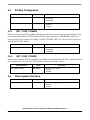
2.5
PCI Bus Configuration
Reset Parameter
Signal
Description
RST_CONF_PCI66EN
EMB_AD[7]
Enable 66 MHz PCI operation
0 PCI 33 MHz
1 PCI 66 MHz
RST_CONF_PCIARB
EMB_AD[15]
Internal PCI arbiter signals
0 Disabled
1 Enabled
2.5.1
RST_CONF_PCI66EN
This bit sets the proper PCI bus timing, although you still need to set the clock speed appropriately. This
bit in conjunction with the PCI_DIV System Clock Frequency Register 1 (IMMRBAR+ 0x0f0c) will
provide proper PCI bus timing. See chapter 5 of MPC5121ERM, MPC5121e Microcontroller Reference
Manual, for PCI_DIV details.
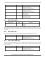
Reset Parameter
RST_CONF_PCI66EN
2.5.2
Signal
EMB_AD[7]
Description
Enable 66 MHz PCI operation
0 PCI 33 MHz
1 PCI 66 MHz
RST_CONF_PCIARB
This bit directs whether the PCI is enabled or not. This essentially disables the PCI bus completely. When
this configuration is selected, PCI_GNT0 (ball E25) must be tied high—inactive.
Reset Parameter
RST_CONF_PCIARB
2.6
Signal
EMB_AD[15]
Description
Internal PCI arbiter signals
0 Disabled
1 Enabled
Other System Functions
Reset Parameter
RST_CONF_SWEN
Signal
EMB_AD[2]
Description
Enables watchdog timer at reset
0 Disabled
1 Enabled
Understanding the Reset Configuration Word for the MPC5121e, Rev. 1
Freescale Semiconductor
33
Reset Parameter
Signal
Description
RST_CONF_TPR
EMB_AD[3]
Factory test mode
0 Disabled (normal operation)
1 Enabled (Freescale factory test only)
RST_CONF_COREDIS
EMB_AD[4]
Core disable mode
0 Disabled (normal operation)
1 Enabled (Freescale factory test only)
RST_CONF_TLE
EMB_AD[6]
Endian mode
0 Big endian mode
1 Little endian mode
RST_CONF_CKS_IN
EMB_AD[22]
Checkstop
0 Checkstop input disabled
1 Checkstop input enabled
2.6.1
RST_CONF_SWEN
Reset Parameter
RST_CONF_SWEN
Signal
EMB_AD[2]
Description
Enables watchdog timer at reset
0 Disabled
1 Enabled
This bit enables the software watchdog timer. The default time for this timer is the maximum count. It is
driven by the input oscillator. For an input frequency of 33 MHz, the watchdog timer will time out in about
128 seconds.
2.6.2
RST_CONF_TPR
This bit is used for the factory test mode. For normal operation, this signal must be set to low.
Reset Parameter
RST_CONF_TPR
2.6.3
Signal
EMB_AD[3]
Description
Factory Test Mode
0 Disabled (normal operation)
1 Enabled (Freescale factory test only)
RST_CONF_CORE_DIS
This bit is used for factory testing of the SOC. For normal operation, this signal must be tied low. The pin
is called “Core Disable,” so it’s a double negative. In other words, you need to disable the disable signal
to have an enable.
Reset Parameter
RST_CONF_COREDIS
Signal
EMB_AD[4]
Description
Core disable mode
0 Disabled (normal operation)
1 Enabled (Freescale factory test only)
Understanding the Reset Configuration Word for the MPC5121e, Rev. 1
34
Freescale Semiconductor
2.6.4
RST_CONF_TLE
Reset Parameter
RST_CONF_TLE
Signal
EMB_AD[6]
Description
Endian mode
0 Big endian mode
1 Little endian mode
This bit directs the e300 core to operate in true little endian mode. The true little endian mode is another
enhanced capability of the e300 core. The true little endian mode actually operates on true little endian
instructions and data from memory.
For most applications, this bit will normally be set to 0, big endian mode. This bit has no other effects on
the SOC itself.
2.6.5
RST_CONF_CKS_IN
Reset Parameter
RST_CONF_CKS_IN
Signal
EMB_AD[22]
Description
Checkstop
0 Checkstop input disabled
1 Checkstop input enabled
This bit sets the pin multiplexing on this pin AA to (CHSTP) checkstop in as the default value. With this
bit set, the checkstop is now the default pin setting.
3
References
1. MPC5121ERM, MPC5121e Microcontroller Reference Manual
2. E300CORERM, e300 Power Architecture™ Core Family Reference Manual
4
Revision History
Revision
Date
Comments
Original release
16 September 2008
M. Ruthenbeck (MAR) – Original Version
Version 0.1
19 September 2008
MAR – revised based on feedback from M. Capistran
Version 1
21 September 2010
Corrected information for reset parameter RST_CONF_ROMLOC.
Value of binary 10 was = LPC boot (and 4K NFC page size). Changed
to 10 = Reserved.
Understanding the Reset Configuration Word for the MPC5121e, Rev. 1
Freescale Semiconductor
35
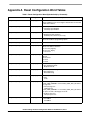
Appendix A Reset Configuration Word Tables
Table 5. Reset Configuration Word (Alphabetically by Parameter)
Reset Parameter
Signal
Description
RST_CONF_BMS
EMB_AD[5]
Boot mode select
Selects e300 boot vector and configures default value for LPC CS0
or NFC base address
RST_CONF_CKS_IN
EMB_AD[22]
Checkstop
0 Checkstop input disabled
1 Checkstop input enabled
RST_CONF_COREDIS
EMB_AD[4]
Core disable mode
0 Disabled (normal operation)
1 Enabled (Freescale factory test only)
RST_CONF_COREPLL
EMB_AD[13:10]
Core PLL multiply factor
See clock module for programming options
RST_CONF_EMB_AD14
EMB_AD[14]
Reserved — must be connected to 1
RST_CONF_LPC_AX
EMB_AD[9:8]
LPC address extension mode
00 No LPC address extension
01 Use LPC_AX[pata]
10 Use LPC_AX[nfc]
11 Reserved
RST_CONF_LPC_DBW
EMB_AD[19:18]
LPC data port size
00 8-bit
10 Reserved
01 16-bit
11 32-bit
RST_CONF_LPC_MX
EMB_AD[16]
LPC mux mode configuration
0 Non-multiplexed mode
1 Multiplexed mode
RST_CONF_LPC_WA
EMB_AD[17]
LPC word/byte addressing
0 Byte addressing
1 Word addressing
RST_CONF_NFC_DBW
EMB_AD[21]
NFC data port size
0 8-bit
1 16-bit
RST_CONF_NFC_PS
EMB_AD[20]
NAND flash page size
if RST_CONF_ROMLOC = 01 then RST_CONF_NFC_PS defines
the page size:
0 512-byte page size
1 2 KB page size
if RST_CONF_ROMLOC = 11 then RST_CONF_NFC_PS defines
the spare size with a fixed page size of 4K:
0 64 bytes spare size
1 218 bytes spare size
RST_CONF_PCI66EN
EMB_AD[7]
Enable 66 MHz PCI operation
0 PCI 33MHz
1 PCI 66MHz
Understanding the Reset Configuration Word for the MPC5121e, Rev. 1
36
Freescale Semiconductor
Table 5. Reset Configuration Word (Alphabetically by Parameter) (continued)
Reset Parameter
Signal
Description
RST_CONF_PCIARB
EMB_AD[15]
Internal PCI arbiter signals
0 Disabled
1 Enabled
RST_CONF_ROMLOC
EMB_AD[1:0]
Selects boot device
00 LPC boot
01 NAND (NFC) boot
10 Reserved
11 NAND (NFC) boot (see also definition of ST_CONF_NFC_PS)
RST_CONF_SWEN
EMB_AD[2]
Enables watchdog timer at reset
0 Disabled
1 Enabled
RST_CONF_SYSDIV
LPC_AX[3],
EMB_AD[31:27]
System PLL divider
See, “MPC5121e Clocks,” for programming options.
RST_CONF_SYSOSCEN
EMB_AX02
Oscillator bypass mode
0 System oscillator bypass mode
1 System oscillator mode
RST_CONF_SYSPLL
EMB_AD[26:23]
System PLL multiply factor
See, “MPC5121e Clocks,” for programming options.
RST_CONF_TLE
EMB_AD[6]
Endian mode
0 Big endian mode
1 Little endian mode
RST_CONF_TPR
EMB_AD[3]
Factory test mode
0 Disabled (normal operation)
1 Enabled (Freescale factory test only)
Table 6. Reset Configuration Word (By Signal EMB_AD[])
Signal
Reset Parameter
Description
EMB_AD[1:0]
RST_CONF_ROMLOC
Selects boot device1
00 LPC boot
01 NAND (NFC) boot
10 Reserved
11 NAND (NFC) boot see also definition of ST_CONF_NFC_PS
EMB_AD[2]
RST_CONF_SWEN
Enables watchdog timer at reset
0 Disabled
1 Enabled
EMB_AD[3]
RST_CONF_TPR
Factory test mode
0 Disabled (normal operation)
1 Enabled (Freescale factory test only)
EMB_AD[4]
RST_CONF_COREDIS
Core disable mode3
0 Disabled (normal operation)
1 Enabled (Freescale factory test only)
EMB_AD[5]
RST_CONF_BMS
Boot mode select
Selects e300 boot vector and configures default value for LPC
CS0 or NFC base address.”
Understanding the Reset Configuration Word for the MPC5121e, Rev. 1
Freescale Semiconductor
37
Table 6. Reset Configuration Word (By Signal EMB_AD[]) (continued)
Signal
Reset Parameter
Description
EMB_AD[6]
RST_CONF_TLE
Endian mode
0 Big endian mode
1 Little endian mode
EMB_AD[7]
RST_CONF_PCI66EN
Enable 66 MHz PCI operation
0 PCI 33 MHz
1 PCI 66 MHz
EMB_AD[9:8]
RST_CONF_LPC_AX
LPC address extension mode
00 No LPC address extension
01 Use LPC_AX[pata]
10 Use LPC_AX[nfc]
11 Reserved
EMB_AD[13:10]
RST_CONF_COREPLL
Core PLL multiply factor
See, “MPC5121e Clocks,” for programming options.
EMB_AD[14]
RST_CONF_EMB_AD14
Reserved — must be connected to 1
EMB_AD[15]
RST_CONF_PCIARB
Internal PCI arbiter signals
0 Disabled
1 Enabled
EMB_AD[16]
RST_CONF_LPC_MX
LPC mux mode configuration
0 Non-multiplexed mode
1 Multiplexed mode
EMB_AD[17]
RST_CONF_LPC_WA
LPC word/byte addressing
0 Byte addressing
1 Word addressing
EMB_AD[19:18]
RST_CONF_LPC_DBW
LPC data port size
00 8-bit
10 Reserved
01 16-bit
11 32-bit
EMB_AD[20]
RST_CONF_NFC_PS
NAND flash page size
if RST_CONF_ROMLOC = 01 then RST_CONF_NFC_PS
defines the page size:
0 512-byte page size
1 2 KB page size
if RST_CONF_ROMLOC = 11 then
RST_CONF_NFC_PS defines the spare size with a fixed page
size of 4K:
0 64 bytes spare size
1 218 bytes spare size
EMB_AD[21]
RST_CONF_NFC_DBW
NFC data port size
0 8-bit
1 16-bit
Understanding the Reset Configuration Word for the MPC5121e, Rev. 1
38
Freescale Semiconductor
Table 6. Reset Configuration Word (By Signal EMB_AD[]) (continued)
Signal
Reset Parameter
Description
EMB_AD[22]
RST_CONF_CKS_IN
Checkstop
0 Checkstop input disabled
1 Checkstop input enabled
EMB_AD[26:23]
RST_CONF_SYSPLL
System PLL multiply factor
See clock module for programming options
LPC_AX[3],
EMB_AD[31:27]
RST_CONF_SYSDIV
System PLL divider
See clock module for programming options
EMB_AX02
RST_CONF_SYSOSCEN
Oscillator bypass mode
0 System oscillator bypass mode
1 System oscillator mode
Table 7. Reset Configuration Word (As Presented in the MPC5121e Reference Manual)
Reset Parameter
Signal
Description
RST_CONF_BMS
EMB_AD[5]
Boot mode select
Selects e300 boot vector and configures default value
for LPC CS0 or NFC base address.”
RST_CONF_ROMLOC
EMB_AD[1:0]
Selects boot device1
00 LPC boot
01 NAND (NFC) boot
10 Reserved
11 NAND (NFC) boot see also definition of
ST_CONF_NFC_PS
RST_CONF_SWEN
EMB_AD[2]
Enables watchdog timer at reset
0 Disabled
1 Enabled
RST_CONF_LPC_MX
EMB_AD[16]
LPC mux mode configuration
0 Non-multiplexed mode
1 Multiplexed mode
RST_CONF_LPC_AX
EMB_AD[9:8]
LPC address extension mode
00 No LPC address extension
01 Use LPC_AX[pata]
10 Use LPC_AX[nfc]
11 Reserved
RST_CONF_LPC_DBW
EMB_AD[19:18]
LPC data port size
00 8-bit
10 Reserved
01 16-bit
11 32-bit
Understanding the Reset Configuration Word for the MPC5121e, Rev. 1
Freescale Semiconductor
39
Table 7. Reset Configuration Word (As Presented in the MPC5121e Reference Manual) (continued)
Reset Parameter
Signal
Description
RST_CONF_NFC_PS
EMB_AD[20]
NAND flash page size
if RST_CONF_ROMLOC = 01 then
RST_CONF_NFC_PS defines the page size:
0 512-byte page size
1 2 KB page size
if RST_CONF_ROMLOC = 11 then
RST_CONF_NFC_PS defines the spare size with a
fixed page size of 4K:
0 64 bytes spare size
1 218 bytes spare size
RST_CONF_NFC_DBW
EMB_AD[21]
NFC data port size
0 8-bit
1 16-bit
RST_CONF_CKS_IN
EMB_AD[22]
Checkstop
0 Checkstop input disabled
1 Checkstop input enabled
RST_CONF_COREPLL
EMB_AD[13:10]
Core PLL multiply factor
See, “MPC5121e Clocks,” for programming options.
RST_CONF_SYSPLL
EMB_AD[26:23]
System PLL multiply factor
See, “MPC5121e Clocks,” for programming options.
RST_CONF_SYSOSCEN
EMB_AX02
Oscillator bypass mode
0 System Oscillator bypass mode
1 System Oscillator mode
RST_CONF_SYSDIV
LPC_AX[3],
EMB_AD[31:27]
System PLL divider
See, “MPC5121e Clocks,” for programming options.
RST_CONF_TLE
EMB_AD[6]
Endian mode
0 Big endian mode
1 Little endian mode
RST_CONF_LPC_WA
EMB_AD[17]
LPC word/byte addressing
0 Byte addressing
1 Word addressing
RST_CONF_PCI66EN
EMB_AD[7]
Enable 66 MHz PCI operation
0 PCI 33 MHz
1 PCI 66 MHz
RST_CONF_EMB_AD14
EMB_AD[14]
Reserved — must be connected to 1
RST_CONF_PCIARB
EMB_AD[15]
Internal PCI arbiter signals
0 Disabled
1 Enabled
RST_CONF_TPR
EMB_AD[3]
Factory test mode
0 Disabled (normal operation)
1 Enabled (Freescale factory test only)
RST_CONF_COREDIS
EMB_AD[4]
Core disable mode
0 Disabled (normal operation)
1 Enabled (Freescale factory test only)
Understanding the Reset Configuration Word for the MPC5121e, Rev. 1
40
Freescale Semiconductor
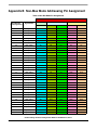
Appendix B Non-Mux Mode Addressing Pin Assignment
Table 8. Non-Mux Mode Pin Assignments
Non-Multiplexed Modes
8-bit Data Bus
16-bit Data Bus
32-bit Data Bus
Ball Number
Pin Assignments
Signal Name
L4
EMB_AD00
D0
D0
D0
D0
D0
L3
EMB_AD01
D1
D1
D1
D1
D1
L2
EMB_AD02
D2
D2
D2
D2
D2
L1
EMB_AD03
D3
D3
D3
D3
D3
M5
EMB_AD04
D4
D4
D4
D4
D4
M3
EMB_AD05
D5
D5
D5
D5
D5
M1
EMB_AD06
D6
D6
D6
D6
D6
N4
EMB_AD07
D7
D7
D7
D7
D7
N3
EMB_AD08
A0
D8
D8
D8
D8
N2
EMB_AD09
A1
D9
D9
D9
D9
N1
EMB_AD10
A2
D10
D10
D10
D10
P3
EMB_AD11
A3
D11
D11
D11
D11
P5
EMB_AD12
A4
D12
D12
D12
D12
P4
EMB_AD13
A5
D13
D13
D13
D13
P2
EMB_AD14
A6
D14
D14
D14
D14
P1
EMB_AD15
A7
D15
D15
D15
D15
R3
EMB_AD16
A8
A0
A1
D16
D16
R1
EMB_AD17
A9
A1
A2
D17
D17
Byte Address Short Address Byte Address Word Address
T2
EMB_AD18
A10
A2
A3
D18
D18
R5
EMB_AD19
A11
A3
A4
D19
D19
T3
EMB_AD20
A12
A4
A5
D20
D20
T4
EMB_AD21
A13
A5
A6
D21
D21
T1
EMB_AD22
A14
A6
A7
D22
D22
T5
EMB_AD23
A15
A7
A8
D23
D23
U3
EMB_AD24
A16
A8
A9
D24
D24
U1
EMB_AD25
A17
A9
A10
D25
D25
V1
EMB_AD26
A18
A10
A11
D26
D26
V2
EMB_AD27
A19
A11
A12
D27
D27
V3
EMB_AD28
A20
A12
A13
D28
D28
U5
EMB_AD29
A21
A13
A14
D29
D29
V4
EMB_AD30
A22
A14
A15
D30
D30
W1
EMB_AD31
A23
A15
A16
D31
D31
W2
EMB_AX00 (ALE)
A24
A16
A17
A0
A2
V5
EMB_AX01 (TSIZ0)
A25
A17
A18
A1
A3
W3
EMB_AX02 (TSIZ1)
A26
A18
A19
A2
A4
Understanding the Reset Configuration Word for the MPC5121e, Rev. 1
Freescale Semiconductor
41
Table 8. Non-Mux Mode Pin Assignments (continued)
Non-Multiplexed Modes
8-bit Data Bus
16-bit Data Bus
32-bit Data Bus
Ball Number
Pin Assignments
Signal Name
W4
LPC_AX03 (TS)
A27
A19
A20
A3
A5
G2
LPC_AX04
A28
A20
A21
A4
A6
G3
LPC_AX05
A29
A21
A22
A5
A7
H5
LPC_AX06
A30
A22
A23
A6
A8
J2
LPC_AX07
A31
A23
A24
A7
A9
H1
LPC_AX08
Logic 0
A24
A25
A8
A10
G4
LPC_AX09
Logic 0
A25
A26
A9
A11
Byte Address Short Address Byte Address Word Address
Understanding the Reset Configuration Word for the MPC5121e, Rev. 1
42
Freescale Semiconductor
Appendix C Mux Mode Addressing Pin Assignments
Table 9. Mux Mode Pin Assignments
External Signals In Multiplexed Mode
8-bit Data Bus
Address
Phase
Isolation
16-bit Data Bus
8-bit
Data
Phase
Address
Phase
8-bit Data
Isolation
32-bit Data Bus
16-bit
Data
Phase
Address
Phase
16-bit Data
Isolation
32-bit
Data
Phase
32-bit Data
L4 EMB_AD00
A0
A0
D0
A0
A0
D0
A0
A0
D0
L3 EMB_AD01
A1
A1
D1
A1
A1
D1
A1
A1
D1
L2 EMB_AD02
A2
A2
D2
A2
A2
D2
A2
A2
D2
L1 EMB_AD03
A3
A3
D3
A3
A3
D3
A3
A3
D3
M5 EMB_AD04
A4
A4
D4
A4
A4
D4
A4
A4
D4
M3 EMB_AD05
A5
A5
D5
A5
A5
D5
A5
A5
D5
M1 EMB_AD06
A6
A6
D6
A6
A6
D6
A6
A6
D6
N4 EMB_AD07
A7
A7
D7
A7
A7
D7
A7
A7
D7
N3 EMB_AD08
A8
A8
0
A8
A8
D8
A8
A8
D8
N2 EMB_AD09
A9
A9
0
A9
A9
D9
A9
A9
D9
N1 EMB_AD10
A10
A10
0
A10
A10
D10
A10
A10
D10
P3 EMB_AD11
A11
A11
0
A11
A11
D11
A11
A11
D11
P5 EMB_AD12
A12
A12
0
A12
A12
D12
A12
A12
D12
P4 EMB_AD13
A13
A13
0
A13
A13
D13
A13
A13
D13
P2 EMB_AD14
A14
A14
0
A14
A14
D14
A14
A14
D14
P1 EMB_AD15
A15
A15
0
A15
A15
D15
A15
A15
D15
R3 EMB_AD16
A16
A16
0
A16
A16
0
A16
A16
D16
R1 EMB_AD17
A17
A17
0
A17
A17
0
A17
A17
D17
T2 EMB_AD18
A18
A18
0
A18
A18
0
A18
A18
D18
R5 EMB_AD19
A19
A19
0
A19
A19
0
A19
A19
D19
T3 EMB_AD20
A20
A20
0
A20
A20
0
A20
A20
D20
T4 EMB_AD21
A21
A21
0
A21
A21
0
A21
A21
D21
T1 EMB_AD22
A22
A22
0
A22
A22
0
A22
A22
D22
T5 EMB_AD23
A23
A23
0
A23
A23
0
A23
A23
D23
U3 EMB_AD24
A24
A24
0
A24
A24
0
A24
A24
D24
U1 EMB_AD25
A25
A25
0
A25
A25
0
A25
A25
D25
V1 EMB_AD26
A26
A26
0
A26
A26
0
A26
A26
D26
V2 EMB_AD27
A27
A27
0
A27
A27
0
A27
A27
D27
V3 EMB_AD28
A28
A28
0
A28
A28
0
A28
A28
D28
U5 EMB_AD29
A29
A29
0
A29
A29
0
A29
A29
D29
V4 EMB_AD30
A30
A30
0
A30
A30
0
A30
A30
D30
W1 EMB_AD31
A31
A31
0
A31
A31
0
A31
A31
D31
Understanding the Reset Configuration Word for the MPC5121e, Rev. 1
Freescale Semiconductor
43
Table 9. Mux Mode Pin Assignments (continued)
External Signals In Multiplexed Mode
8-bit Data Bus
Address
Phase
Isolation
16-bit Data Bus
8-bit
Data
Phase
Address
Phase
8-bit Data
Isolation
32-bit Data Bus
16-bit
Data
Phase
Address
Phase
Isolation
16-bit Data
32-bit
Data
Phase
32-bit Data
W2 EMB_AX00
(ALE)
ALE
ALE
ALE
ALE
ALE
ALE
ALE
ALE
ALE
V5 EMB_AX01
(TSIZ0)
TSIZ0
TSIZ0
TSIZ0
TSIZ0
TSIZ0
TSIZ0
TSIZ0
TSIZ0
TSIZ0
W3 EMB_AX02
(TSIZ1)
TSIZ1
TSIZ1
TSIZ1
TSIZ1
TSIZ1
TSIZ1
TSIZ1
TSIZ1
TSIZ1
W4 LPC_AX03
(TS)
1
1
TS
1
1
TS
1
1
TS
Table 10. Mux Mode Pin Assignments: Shortword Addressing Mode
External Signals In Multiplexed Mode (Shortword Addressing)
Address
Phase
Isolation
Data
Phase
Address
Phase
8-bit Data Bus
Isolation
Data
Phase
Address
Phase
16-bit Data Bus
Isolation
Data
Phase
32-bit Data Bus
L4 EMB_AD00
A0
A0
D0
A1
A1
D0
A2
A2
D0
L3 EMB_AD01
A1
A1
D1
A2
A2
D1
A3
A3
D1
L2 EMB_AD02
A2
A2
D2
A3
A3
D2
A4
A4
D2
L1 EMB_AD03
A3
A3
D3
A4
A4
D3
A5
A5
D3
M5 EMB_AD04
A4
A4
D4
A5
A5
D4
A6
A6
D4
M3 EMB_AD05
A5
A5
D5
A6
A6
D5
A7
A7
D5
M1 EMB_AD06
A6
A6
D6
A7
A7
D6
A8
A8
D6
N4 EMB_AD07
A7
A7
D7
A8
A8
D7
A9
A9
D7
N3 EMB_AD08
A8
A8
0
A9
A9
D8
A10
A10
D8
N2 EMB_AD09
A9
A9
0
A10
A10
D9
A11
A11
D9
N1 EMB_AD10
A10
A10
0
A11
A11
D10
A12
A12
D10
P3 EMB_AD11
A11
A11
0
A12
A12
D11
A13
A13
D11
P5 EMB_AD12
A12
A12
0
A13
A13
D12
A14
A14
D12
P4 EMB_AD13
A13
A13
0
A14
A14
D13
A15
A15
D13
P2 EMB_AD14
A14
A14
0
A15
A15
D14
A16
A16
D14
P1 EMB_AD15
A15
A15
0
A16
A16
D15
A17
A17
D15
R3 EMB_AD16
A16
A16
0
A17
A17
0
A18
A18
D16
R1 EMB_AD17
A17
A17
0
A18
A18
0
A19
A19
D17
T2 EMB_AD18
A18
A18
0
A19
A19
0
A20
A20
D18
R5 EMB_AD19
A19
A19
0
A20
A20
0
A21
A21
D19
T3 EMB_AD20
A20
A20
0
A21
A21
0
A22
A22
D20
Understanding the Reset Configuration Word for the MPC5121e, Rev. 1
44
Freescale Semiconductor
Table 10. Mux Mode Pin Assignments: Shortword Addressing Mode (continued)
External Signals In Multiplexed Mode (Shortword Addressing)
Address
Phase
Isolation
Data
Phase
Address
Phase
8-bit Data Bus
Isolation
Data
Phase
Address
Phase
16-bit Data Bus
Isolation
Data
Phase
32-bit Data Bus
T4 EMB_AD21
A21
A21
0
A22
A22
0
A23
A23
D21
T1 EMB_AD22
A22
A22
0
A23
A23
0
A24
A24
D22
T5 EMB_AD23
A23
A23
0
A24
A24
0
A25
A25
D23
U3 EMB_AD24
A24
A24
0
A25
A25
0
A26
A26
D24
U1 EMB_AD25
A25
A25
0
A26
A26
0
A27
A27
D25
V1 EMB_AD26
A26
A26
0
A27
A27
0
A28
A28
D26
V2 EMB_AD27
A27
A27
0
A28
A28
0
A29
A29
D27
V3 EMB_AD28
A28
A28
0
A29
A29
0
A30
A30
D28
U5 EMB_AD29
A29
A29
0
A30
A30
0
A31
A31
D29
V4 EMB_AD30
A30
A30
0
A31
A31
0
0
0
D30
W1 EMB_AD31
A31
A31
0
0
0
0
0
0
D31
W2 EMB_AX00
(ALE)
ALE
ALE
ALE
ALE
ALE
ALE
ALE
ALE
ALE
V5 EMB_AX01
(TSIZ0)
TSIZ0
TSIZ0
TSIZ0
TSIZ0
TSIZ0
TSIZ0
TSIZ0
TSIZ0
TSIZ0
W3 EMB_AX02
(TSIZ1)
TSIZ1
TSIZ1
TSIZ1
TSIZ1
TSIZ1
TSIZ1
TSIZ1
TSIZ1
TSIZ1
W4 LPC_AX03
(TS)
1
1
TS
1
1
TS
1
1
TS
Understanding the Reset Configuration Word for the MPC5121e, Rev. 1
Freescale Semiconductor
45
Appendix D NAND Flash Pin Connections
Table 11. NAND Flash Pin Connections
Package Pin Number 16-Bit NAND Bus Width 8-Bit NAND Bus Width
EMB_AD16
NFC_D0
NFC_D0
EMB_AD17
NFC_D1
NFC_D1
EMB_AD18
NFC_D2
NFC_D2
EMB_AD19
NFC_D3
NFC_D3
EMB_AD20
NFC_D4
NFC_D4
EMB_AD21
NFC_D5
NFC_D5
EMB_AD22
NFC_D6
NFC_D6
EMB_AD23
NFC_D7
NFC_D7
EMB_AD24
NFC_D8
EMB_AD25
NFC_D9
EMB_AD26
NFC_D10
EMB_AD27
NFC_D11
EMB_AD28
NFC_D12
EMB_AD29
NFC_D13
EMB_AD30
NFC_D14
EMB_AD31
NFC_D15
Understanding the Reset Configuration Word for the MPC5121e, Rev. 1
46
Freescale Semiconductor
Freescale Semiconductor
User Guide
MPC5121e DRAM Controller
by: Michael Winge
IMT Application Engineer
Chris Alger
IMT System Engineer
Charles Melear
IMT System Engineer
This section of the MPC5121e quick reference user
guide describes the configuration of the SDRAM
controller implemented in the Freescale MPC5121e. The
power supply for different DDR SDRAMs, all possible
connections between DDR SDRAM and MPC5121e,
and configuration of all DDR SDRAM timing
parameters will be described, and an example using the
ADS5121 revision 4 will be provided. A supplement to
this document is an Excel spreadsheet that will take
parameters from a memory datasheet and generate the
register settings required to work with that DDR
SDRAM.
Contents
1
2
3
4
5
6
1
Introduction
The MPC5121e is a Freescale Power Architecture™
device developed for the multimedia and telemetric
market. It is the successor to the MPC5200B but
provides more features. For example, it provides these
modules:
• DIU (display interface unit)
© Freescale Semiconductor, Inc., 2009. All rights reserved.
7
8
Introduction . . . . . . . . . . . . . . . . . . . . . . . . . . . . . . . . . .
Overview . . . . . . . . . . . . . . . . . . . . . . . . . . . . . . . . . . . .
2.1 DDR SDRAM. . . . . . . . . . . . . . . . . . . . . . . . . . . . .
2.2 MPC5121e DRAM Controller . . . . . . . . . . . . . . . .
DDR SDRAM Connection to MPC5121e. . . . . . . . . . . .
3.1 Connections for 16-Bit Data Width Mode . . . . . . .
3.2 Connections for 32-Bit Data Width Mode . . . . . . .
3.3 Power Supply . . . . . . . . . . . . . . . . . . . . . . . . . . . .
Clock Generation for the DRAM Controller . . . . . . . . . .
DRAM Controller Initialization . . . . . . . . . . . . . . . . . . . .
5.1 Memory Configuration . . . . . . . . . . . . . . . . . . . . . .
5.2 MPC5121e DDR SDRAM I/O Configuration . . . . .
5.3 DRAM Controller Configuration . . . . . . . . . . . . . . .
5.4 Configuration Register Descriptions . . . . . . . . . . .
5.5 Timing Configuration Parameters . . . . . . . . . . . . .
Usage of the DRAM Controller Command Registers . .
6.1 Compact Command Register . . . . . . . . . . . . . . . .
6.2 Command Register . . . . . . . . . . . . . . . . . . . . . . . .
Example. . . . . . . . . . . . . . . . . . . . . . . . . . . . . . . . . . . . .
7.1 Connection of the DDR2 SDRAM . . . . . . . . . . . . .
7.2 MPC5121e DRAM Controller Initialization Tool. . .
7.3 DRAM Controller Configuration Example . . . . . . .
7.4 DDR2 SDRAM Initialization Sequence . . . . . . . . .
References . . . . . . . . . . . . . . . . . . . . . . . . . . . . . . . . . .
47
48
48
57
57
58
60
63
64
65
65
66
66
67
74
77
77
81
84
84
85
85
90
93
Overview
•
•
PowerVR® MBX Lite IP core (graphic engine from Imagination Technologies with 3D
acceleration support)
AXE audio coprocessor
The modules mentioned above plus the Power Architecture core and some of the peripherals (using the
same internal bus) require access to RAM. The MPC5121e DRAM controller is a multi-master controller
which supports up to five masters.
The SDRAM controller supports these RAM types:
• DDR1 SDRAM
• DDR2 SDRAM
• Mobile-DDR/LPDDR (low-power DDR) SDRAM
2
Overview
2.1
DDR SDRAM
DDR1, DDR2, and Mobile-DDR are DDR SDRAMs (double data rate synchronous dynamic random
access memory).
2.1.1
Double Data Rate
A double data rate (DDR) SDRAM transfers data on the rising and falling edges of the bus clock signal.
To avoid clocking the memory cells with the double frequency of the bus clock signal, a pre-fetch buffer
is used. During one access of the memory the double amount of data will be stored in the pre-fetch buffer.
During data transfer the first half of data will be transferred on the rising edge of the clock signal, and the
second half during the falling edge of the clock signal.
2.1.2
History
Synchronous DRAMs are very widely used, particularly in desktop and laptop computers. In fact, these
new types of memory are quite common even in embedded computer systems.
The design and use of synchronous DRAMs is significantly different from other types of memory. To
understand synchronous DRAM operation, it is important to understand how memory elements have
evolved. Also, it is important to realize that synchronous DRAMs use signal names that are common to
other memory devices. There are cases where the function of certain signals has changed but the original
name is still used. This can obviously cause confusion in trying to learn a new technology. Therefore, a
brief history of memory elements is in order.
The first solid state memory elements were static RAMs and ROMs. A ROM (read only memory) presents
a simple, basic structure. A ROM can be mask programmed by the manufacturer. Other types of ROM can
be programmed, erased, and then reprogrammed in the field. Some ROMs can be erased with ultraviolet
light while others can be erased by applying various electrical voltages. In all of these cases, the
microcontroller reads the contents of the ROM by outputting an address, a chip enable, and an output
enable. After some read delay time, data is output by the ROM and read by the microcontroller.
MPC5121e DRAM Controller, Rev. 2
48
Freescale Semiconductor
Overview
Static RAMs (random access memory) also have an address and data bus. Static RAMs require the same
signals as a ROM in addition to a read/write signal. The major difference between static RAMs and ROMs
is that the memory contents of the static RAM can be modified. However, in general, the microcontroller
accesses the static RAM by outputting an address, setting the read/write appropriately, and then reading or
writing data to the data bus as required. For these devices, the address and data bus are separate structures.
Dynamic random access memories or DRAMs also have an address and data bus. Unlike static RAMs,
DRAMs must be refreshed periodically. That is, every 2 milliseconds or so, the contents of each memory
cell must be read and then written back to the same value. The memory cells can be thought of as a small
capacitor that holds a charge. The cells must be refreshed before the charge bleeds off the capacitor. One
advantage of DRAMs over static RAMs is that the DRAM memory cells are significantly smaller than
those of static RAMs. Thus the memory density is much greater. Because of the larger memory capacity,
more address lines are required. However, to keep packaging costs low and to reduce the amount of pins
required for a particular memory, the address bus is multiplexed.
The microprocessor puts out an address that is routed to a multiplexer. During the first part of the memory
access, the multiplexer drives the low-order address lines to the DRAM. The memory controller asserts
the RAS signal which latches these address bits into the DRAM. The multiplexer then switches state, and
then drives the upper part of the address. The memory controller asserts CAS, which latches these address
bits into the DRAM. After a suitable access time has expired, the microprocessor will read the data by
deasserting both RAS and CAS, or the microprocessor will write data to the DRAM data bus and then,
after a suitable setup time, will terminate. This methodology only requires the DRAM to have one-half of
the address lines that are needed to access the same memory space as a static memory which does not use
a multiplexed address bus structure.
Memory controllers for DRAM are reasonably simple, in that they accept all of the address lines from the
microprocessor, then generate a RAS, CAS, and MUX signal. One additional feature that some DRAM
memory controllers also have is automatic refreshing of the DRAM. Basically, in each two millisecond
period, the memory controller must read one location in each row. For a 64 KB memory, 16 address lines
are required. However, to refresh the entire memory, only 256 accesses must be made to the DRAM. That
is, all the combinations of the 8-row address lines must be accessed per refresh period.
In summary, a DRAM controller takes an address from the microcontroller, applies the lower half of the
address to the memory, asserts RAS, applies the upper half of the address to the memory, and reads or
writes data.
When referring to DRAMs, RAS and CAS stand for row address strobe and column address strobe,
respectively. These same terms are used in synchronous DRAMS, in other words, single and double data
rate memories. However, in that case these terms do not have the same meaning.
Keeping in mind this history and explanation of how various memories function, now we will provide a
description of how single and double data rate synchronous DRAMs operate.
2.1.3
Single and Double Data Rate Memory Operation
So far, reading and writing memory elements did not require a complex set of actions. One feature
requiring some complexity in a memory controller was to have automatic refresh in DRAMs. However,
reading SDR and DDR memory is more complex. Some type of memory controller for SDR and DDR
MPC5121e DRAM Controller, Rev. 2
Freescale Semiconductor
49
Overview
memory is almost required. Accessing SDR and DDR SDRAMs requires more than just applying an
address and then reading or writing data.
Single and double data rate SDRAMs have the general structure shown in Figure 1. The memory is
composed of banks. The number of banks is usually one, two, or four but can be greater. Within each bank
are a number of rows. The number of rows per bank is a power of two. Within each row are accessible
memory locations. Once again, the number of memory locations in each row will be equal to a power of
two.
Sense Amplifiers
CS#
WE#
CAS#
RAS#
Command
Decode
CKE
CLK
Control
Logic
Bank 3
Bank 2
Bank 1
Bank 0
Mode Register
Refresh 11
Counter
11
Row11
Address
Mux
Bank 0
RowAddress
Latch &
Decoder
2048
Bank 0
Memory
Array
(204825632)
32
8192
I/O Gating
DQM Mask Logic
Read Data Latch
Write Drivers
2
A0–A10,
BA0, BA1
Address
13 Register
2
Bank
Control
Logic
ColumnAddress
Counter/
Latch
256
32)
4
4
Data
Output
Register
32
32
DQM0–
DQM3
DQ0–
DQ31
Data
Input
Register
Column
Decoder
8
Figure 1. General Structure of Single and Double Data Rate SDRAMs
Reading and writing SDRAMs is fundamentally different from accessing a normal DRAM. SDRAMs are
accessed by using a command or series of commands. The commands that can be issued to an SDRAM are:
• No operation
• Active
• Read
• Write
• Burst terminate
• Precharge
• Self-refresh
• Load mode register
MPC5121e DRAM Controller, Rev. 2
50
Freescale Semiconductor
Overview
•
•
Write enable
Write inhibit
These commands are used to select a particular bank in the SDRAM, activate a row within a bank, and
then read or write a particular memory location in the selected row. If no more accesses are going to be
made to this row, a precharge command is issued to deactivate the row and bank. In general, to read or
write a particular memory location, the memory controller would issue a precharge command to close any
open rows and deactivate any open banks. An active command is issued to open a particular row and bank.
Then a read or write command is issued to access the required memory location. Accessing another
memory location in the currently active and open bank and row does not require a precharge command.
Commands are issued to the SDRAM by driving the chip select (CS), row address strobe (RAS), column
address strobe (CAS), and write enable (WE) lines. When the CS line is driven low along with CAS, RAS,
and/or WE, the SDRAM interprets this as a command. An example of a read command is shown in
Figure 2.
Read Command
CLK
CKE
High
CS#
RAS#
CAS#
WE#
A0-A7
Column
Address
A8, A9
Enable Auto Precharge
A10
Disable Auto Precharge
BA0, 1
Bank
Address
Don’t Care
Figure 2. Example of the Read Command
To perform an access to a random memory location, an active — read/write — precharge command
sequence is performed. An example of this is shown in Figure 3.
MPC5121e DRAM Controller, Rev. 2
Freescale Semiconductor
51
Overview
Single Read
T0
T1
tCK
CLK
tCL
T4
T3
T2
T5
tCH
tCK
tCKS
tCKH
tCMS
tCMH
CKE
COMMAND
Active
NOP
Read
tCMS
DQM/
QML, DQMH
tAS
tAS
Column m2
tAS
Active
tAH
Row
All Banks
Row
A10
BA0, BA1
NOP
tAH
Row
A0–A9
Precharge
tCMH
Row
Disable Auto Precharge Single Bank
tAH
Bank
Bank
Bank
Bank
tOH
tAC
DQ
tLZ
tRCD
tRAS
DOutm
tHZ
CAS Latency
tRP
tRC
Don’t Care
Undefined
Figure 3. Example of an Active — Read/Write — Precharge Command Sequence
At this point a brief explanation of accessing the SDRAM to read and write data has been offered. It is very
important to note that usually some type of memory controller sits between the CPU’s address/data bus
structure and the external SDRAM. The CPU simply outputs an address on its internal bus to the SDRAM
bus memory controller. The memory controller interfaces the internal CPU address/data bus to the external
SDRAM. It is the responsibility of the SDRAM bus memory controller to accept an address from the CPU,
determine if a precharge cycle needs to be run, run an active cycle, and then run a read or write cycle. Thus,
determining the need for which cycles need to run and then driving the SDRAM memory correctly is
totally transparent to the CPU. The CPU simply outputs an address, then waits for the memory controller
to access the SDRAM with the appropriate command sequence and then return an acknowledgement to
the CPU, terminating the memory access.
Even though SDRAM accesses are complicated compared to accessing other types of memory, specialized
memory controllers are employed to make the task seem transparent to the software programmer. In fact,
using an SDRAM without a specialized memory controller would be extremely difficult, if not impossible.
In the case of the MPC5121e, using SDR and DDR synchronous DRAMs becomes a straightforward
process because of the integrated memory controller.
As a final note on SDRAM usage, connecting and using this type of memory is reasonably simple.
However, SDRAM busses work in the 100–200 MHz range. Layout issues involved with printed circuit
design are extremely important. Keeping lead lengths short — less than three centimeters in length — is
critical. Also, issues with printed circuit board line impedance, if not properly taken into account, will
MPC5121e DRAM Controller, Rev. 2
52
Freescale Semiconductor
Overview
result in signal integrity issues. However, by proper attention to circuit board design issues, SDR and DDR
SDRAMs present a cost-effective, reliable, and simple-to-access memory system.
2.1.4
Differences Between DDR1 and DDR2 SDRAM
Here are the key differences between DDR1 and DDR2:
Table 1. Differences Between DDR1 and DDR2
Differences
DDR1 SDRAM
DDR2 SDRAM
2-bit
4-bit
Memory cell clock
Equal bus clock
Double bus clock
CAS latency (CL)
Usually 2, 2.5, or 3 clock cycles
Usually 3, 4, or 5 clock cycles
Termination
Termination must be done on the board
On-die termination
Burst length
2, 4, and 8
4 and 8
2.5 V
1.8 V
(lower power consumption than DDR1)
—
Depends on the device
Pre-fetch buffer width
Voltage
Additional latency
Because the pre-fetch buffer of the DDR2 is twice that of the DDR1, a read access to the DDR2 will access
at least four consecutive addresses. For the DDR1 two consecutive addresses are accessed.
For a more detailed description of the differences between DDR1 and DDR2, please refer to item 4 in
Section 8, “References.”
2.1.5
Differences Between DDR1 and Mobile-DDR SDRAM
The main difference between DDR1 and mobile-DDR SDRAM is the power consumption, which is
reflected in the input/output interface. The mobile-DDR SDRAM uses a 1.8 V LV-CMOS interface with
a minimal DC power consumption — the DDR1 SDRAM uses the JEDEC standard 2.5 V input/output
interface.
Mobile-DDR has these additional features, which help improve power consumption:
• Temperature-compensated self-refresh (TCSR)
• Partial-array self-refresh (PASR)
• Deep power-down (DPD)
• Clock stop mode
Furthermore, the initialization procedure and the clocking (CL) have been changed. For a more detailed
description of the differences between DDR1 and Mobile-DDR SDRAM please refer to item 5 in
Section 8, “References.”
MPC5121e DRAM Controller, Rev. 2
Freescale Semiconductor
53
Overview
2.1.6
DDR SDRAM Signals
Table 2. DDR SDRAM Signals
Signal(s)
Description
Pins
Comments
CK, CK
Clock: CK and CK are differential clock
signals.
Output
MCK, MCK
CKE
(CKE0)
(CKE1)
Clock enable: CKE high activates internal
Output
clock signals, device input buffers, and output MCKE
drivers of the DDR-SDRAM. CKE low
deactivates them.
One external bank
support
CS
(CS0)
(CS1)
Chip Select: All commands are masked if CS Output
is registered high. CS provides for external
MCS
bank selection on systems with multiple
banks.
One external bank
support
ODT
On-die termination: ODT (registered high)
Output
enables termination resistance internal to the MODT
DDR2 SDRAM. The ODT pin will be ignored if
the EMR(1) is programmed to disable ODT.
DDR2 only
RAS, CAS, WE
Command: RAS, CAS, and WE (along with
CS) define the command being entered.
DM
(LDM)
(UDM)
Input data mask: DM is an input mask signal Output
for write data. Input data is masked when DM MDM [3:0]
is sampled high along with that input data
during a write access. DM is sampled on both
edges of DQS.
16-bit data width:
• LDM is used for DQ0-DQ7
• UDM is used for DQ8-DQ15
32-bit data width:
• DM0 is used for DQ0-DQ7
• DM1 is used for DQ8-DQ15
• DM2 is used for DQ16-DQ23
• DM3 is used for DQ24-DQ31
Output
MRAS, MCAS,
MWE
MPC5121e DRAM Controller, Rev. 2
54
Freescale Semiconductor
Overview
Table 2. DDR SDRAM Signals (continued)
Signal(s)
Description
Pins
Comments
BA[2:0]
Bank address signals: BA0 and BA1 define to Output
which bank an active, read, write or precharge MBA [2:0]
command is being applied.
DDR1 and
Mobile-DDR are
using BA[1:0] only
A[15:0]
Address signals: Provide the row address for Output
active commands, plus the column address MA [15:0]
and auto precharge bit for read/write
commands, to select one location out of the
memory array in the respective bank. A10 is
sampled during a precharge command to
determine whether the precharge applies to
one bank (A10 low) or all banks (A10 high).
Depending on the
DDR SDRAM device,
different numbers of
address signals are
used.
DQ
Data signals
Depending on the
DDR SDRAM device,
different numbers of
data signals are
used.
DQS
(LDQS)
(UDQS)
Data strobe: DRAM controller input with read I/O
data, output with write data. Edge-aligned with MDQS [3:0]
read data, centered in write data. Used to
capture write data.
16-bit data width:
• LDQS is used for DQ0–DQ7
• UDQS is used for DQ8–DQ15
32-bit data width:
• DQS0 is used for DQ0–DQ7
• DQS1 is used for DQ8–DQ15
• DQS2 is used for DQ16–DQ23
• DQS3 is used for DQ24–DQ31
I/O
MDQ [31:0]
For a more detailed description of DDR1, DDR2, and mobile-DDR SDRAM signals please refer to item 6,
item 7, and item 8 in Section 8, “References.”
2.1.7
DDR SDRAM Initialization
Before using the DDR SDRAM the DDR SDRAM must be initialized. The required steps are explained
below.
2.1.7.1
1.
2.
3.
4.
5.
DDR1 SDRAM Initialization
Apply voltage to the DDR1.1
Enable clock to the DDR1.
Wait until power and clock are stable.
Wait 200 µs.
Set CKE high and send at least one NOP or deselect command.
1. Check DDR SDRAM device manual for the correct power-up sequence.
MPC5121e DRAM Controller, Rev. 2
Freescale Semiconductor
55
Overview
6. Send a precharge all command and thereafter wait at least tRP.
7. Send a mode register set command to enable DLL in the extended mode register and thereafter wait
at least tMRD.
8. Send a mode register set command to program the mode register with DLL reset and thereafter wait
at least 200 clock cycles.
9. Send a precharge all command and thereafter wait at least tRP.
10. Send an auto refresh command and thereafter wait at least tRP.
11. Perform step 10 again.
12. Send a mode register set command to program the mode register without DLL reset and thereafter
wait at least tMRD.
DDR1 is in normal operation after 200 clock cycles starting with DLL reset.
2.1.7.2
DDR2 SDRAM Initialization
1. Apply voltage to the DDR2.1
2. Enable clock to the DDR2.
3. Wait until power and clock are stable.
4. Wait for 200 µs and thereafter send at least one NOP or deselect command.
5. Set CKE high.
6. Send NOP or deselect commands for 400 ns.
7. Send a precharge all command and thereafter wait at least tRP.
8. Send a load mode command to program EMR2 and thereafter wait at least tMRD.
9. Send a load mode command to program EMR3 and thereafter wait at least tMRD.
10. Send a load mode command to EMR to enable DLL and thereafter wait at least tMRD.
11. Send a load mode command to program MR with reset DLL and thereafter wait at least tMRD.
12. Send a precharge all command and thereafter wait at least tRP.
13. Send a refresh command and thereafter wait at least tRP.
14. Send a refresh command and thereafter wait at least tRP.1
15. Send a load mode command to program the mode register without DLL reset (A8=0) and thereafter
wait at least tMRD.
16. Wait until 200 clock cycles has passed after step 11 (DLL reset).
17. Send a load mode command to EMR to program OCD and thereafter wait at least tMRD.2
18. Send a load mode command to EMR to enable OCD default and thereafter wait at least tMRD.3
19. Send a load mode command to EMR to enable OCD exit and thereafter wait at least tMRD.3
DDR2 is in normal operation.
1. Perform at least two REFRESH commands.
2. Only required if OCD is used and step 18 and step 19 will not be executed.
3. If OCD is not used, then step 17 shall not be executed and steps 18 and 19 are required.
MPC5121e DRAM Controller, Rev. 2
56
Freescale Semiconductor
DDR SDRAM Connection to MPC5121e
2.1.7.3
Mobile-DDR SDRAM Initialization
1. Apply voltage to the mobile-DDR.1
2. Wait until power is stable.
3. Set CKE high.
4. Enable clock.
5. Send NOP or deselect command for at least 200 µs.
6. Send a precharge all command.
7. Send NOP or deselect command for at least tRP.
8. Send a refresh command.
9. Send NOP or deselect command for at least tRP.
10. Send a refresh command.
11. Send NOP or deselect command for at least tRP.
12. Send a load mode register command to load the standard mode register as desired.
13. Send NOP or deselect command for at least tMRD.
14. Send a load mode register command to load the extended mode register as desired.
15. Send NOP or deselect command for at least tMRD.
Mobile-DDR is in normal operation.
2.2
MPC5121e DRAM Controller
The MPC5121e DRAM controller is a multi-master controller, which manages in parallel the access
requests from all masters to the DDR SDRAM. Depending on the current priority (dynamic priority
assigned to the master by the DRAM controller priority manager) and the arbitration rules which are
described in item 9 in Section 8, “References,” the DRAM controller sends the command from master
which wins the access to the DDR-SDRAM device.
The five bus masters are:
• Master 1 — DIU
• Master 2 — Power Architecture
• Master 3 — AXE
• Master 4 — MBX
• Master 5 — CBS bus (internal peripheral bus)
3
DDR SDRAM Connection to MPC5121e
The MPC5121e DRAM controller supports 16-bit and 32-bit data width mode. In 16-bit data width mode
it is possible to connect one 16-bit data width DDR SDRAM device or two 8-bit data width DDR SDRAM
devices. In 32-bit data width mode it is possible to connect one 32-bit data width DDR SDRAM device,
two 16-bit data width DDR SDRAM devices, or four 8-bit data width DDR SDRAM devices.
MPC5121e DRAM Controller, Rev. 2
Freescale Semiconductor
57
DDR SDRAM Connection to MPC5121e
The pictures below show in high level all the possibilities as to how a DDR SDRAM device can be
connected to the MPC5121e.
NOTE
Depending on the DDR SDRAM device not all address lines (MA[15:0])
are required.
NOTE
DDR1 SDRAM and mobile-SDRAM devices use two bank address lines
only (MBA[1:0]).
NOTE
ODT is used only for the DDR2 SDRAM, but the support must be
configured during DDR SDRAM initialization.
3.1
Connections for 16-Bit Data Width Mode
MDQ[15..0]
MDQ0
MPC5121
MA[31..0]
MDQ15
MBA[2..0]
MA0
MDQ[15..0]
MA15
A0
D0
MBA0
MBA1
MBA2
A15
D15
MDQ15
BA1
BA2
MWE
MCAS
MRAS
MCLK
MCLK
WE
CAS
RAS
CLK
CLK
SDRAM
BA0
MDQS0
MDQS1
MDM0
MDM1
MDQ0
MDQS1
UDQS
MDM0
LDM
UDM
ODT
CS
CKE
MCKE
MDQS0
LDQS
MDM1
MODT
MCS
MCKE
MCLK
MCLK
MCS
MWE
MCAS
MRAS
MODT
MDQS[1..0]
MDM[1..0]
Figure 4. Connection of a 16-Bit Data Width SDRAM Device in 16-Bit Data Mode
MPC5121e DRAM Controller, Rev. 2
58
Freescale Semiconductor
DDR SDRAM Connection to MPC5121e
MDQ[15..0]
MDQ0
MPC5121
MA[31..0]
MDQ[7..0]
MDQ15
MBA[2..0]
MA15
A15
D7
BA0
BA1
BA2
MWE
MCAS
MBA0
MBA1
MBA2
D0
MRAS
MCLK
MCLK
SDRAM 1
MA0
A0
DQS
MDQ0
MDQ7
MDQS0
WE
CAS
RAS
DM
CLK
ODT
CLK
CS
MDQS0
MDQS1
CKE
MDM0
MODT
MCS
MCKE
MDQ[15..8]
MDM0
MDM1
A0
D0
A15
D7
BA0
MCLK
BA1
BA2
MCLK
MWE
MCS
MCAS
MWE
MRAS
MCAS
MRAS
MCLK
MCLK
SDRAM 2
MCKE
DQS
MDQ8
MDQ15
MDQS1
WE
CAS
RAS
CLK
CLK
DM
ODT
CS
CKE
MODT
MDM1
MODT
MCS
MCKE
MDQS[1..0]
MDM[1..0]
Figure 5. Connection of Two 8-Bit Data Width SDRAM devices in 16-Bit Data Mode
NOTE
In Figure 5 a high level connection plan is shown where the power pins and
the termination are not considered.
NOTE
Termination of the signals is not displayed in the pictures above but must be
considered during board design. If DDR2 SDRAM ODT is used, then
on-board termination of the DDR2 SDRAM signals can be ignored.
NOTE
The ODT signal is used only for DDR2 SDRAM, but it is not required. ODT
can be enabled during DDR2 SDRAM initialization.
MPC5121e DRAM Controller, Rev. 2
Freescale Semiconductor
59
DDR SDRAM Connection to MPC5121e
3.2
Connections for 32-Bit Data Width Mode
MDQ[31..0]
MDQ0
MPC5121
MA[31..0]
MDQ15
MBA[2..0]
MA0
MA15
A0
D0
MBA0
MBA1
MBA2
A15
D31
BA0
BA1
BA2
MWE
MCAS
MDM0
MDM1
MDM2
MDM3
MRAS
MCLK
MCLK
WE
CAS
RAS
CLK
CLK
MDQS0
MDQS1
MDQS2
DQS1
DQS2
MDQS3
MDM0
DQS3
DM0
DM1
DM2
DM3
ODT
CS
MCKE
MDQ31
DQS0
SDRAM
MDQS0
MDQS1
MDQS3
MDQS4
MDQ0
CKE
MDM1
MDM2
MDM3
MODT
MCS
MCKE
MCLK
MCLK
MCS
MWE
MCAS
MRAS
MODT
MDQS[3..0]
MDM[3..0]
Figure 6. Connection of a 32-Bit Data Width SDRAM Device in 32-Bit Data Mode
MPC5121e DRAM Controller, Rev. 2
60
Freescale Semiconductor
DDR SDRAM Connection to MPC5121e
MDQ[31..0]
MDQ0
MPC5121
MA[31..0]
MDQ[15..0]
MDQ15
MDQ16
MDQ31
MBA[2..0]
MA15
A15
D15
BA0
BA1
BA2
MWE
MCAS
MBA0
MBA1
MBA2
D0
MRAS
MCLK
MCLK
SDRAM 1
MA0
A0
MDQS0
LDQS
UDQS
CAS
MDQS1
MDM0
MDM1
LDM
UDM
RAS
CLK
ODT
CLK
CS
CKE
MODT
MCS
MCKE
MDQ[31..16]
MDM0
MDM1
MDM2
MDM3
A0
D0
A15
D15
BA0
MCLK
BA1
BA2
MCLK
MWE
MCS
MCAS
MWE
MRAS
MCLK
MCLK
SDRAM 2
MCKE
MRAS
MDQ15
WE
MDQS0
MDQS1
MDQS2
MDQS3
MCAS
MDQ0
MDQ16
MDQ31
MDQS2
MDQS3
LDQS
UDQS
WE
CAS
RAS
CLK
CLK
ODT
CS
CKE
MODT
MDM2
LDM
UDM
MDM3
MODT
MCS
MCKE
MDQS[3..0]
MDM[3..0]
Figure 7. Connection of Two 16-Bit Data Width SDRAM Devices in 32-Bit Data Mode
MPC5121e DRAM Controller, Rev. 2
Freescale Semiconductor
61
DDR SDRAM Connection to MPC5121e
MDQ[31..0]
MDQ0
MPC5121
MA[31..0]
MDQ15
MDQ16
MDQ31
MBA[2..0]
D0
A15
D7
MWE
MA15
MCAS
MRAS
MBA0
MBA1
MBA2
MCLK
MCLK
DM
CLK
ODT
CLK
CS
A0
D0
A15
D7
BA1
BA2
MWE
MCS
MCAS
MWE
MRAS
MRAS
MCLK
MCLK
MDM0
MODT
MCS
D7
MCLK
MCLK
DQS
MDQ15
RAS
ODT
CS
CKE
DM
CLK
ODT
CLK
CS
A0
D0
A15
D7
BA1
BA2
MDQS1
MWE
MDM1
MODT
MCS
MCKE
MRAS
MCLK
MCLK
MDQ23
MDQS2
CAS
CKE
MCAS
DM
DQS
MDQ16
WE
BA0
RAS
MODT
MRAS
MDQ8
CAS
CLK
A15
MCKE
WE
CLK
D0
WE
SDRAM 4
BA0
MCLK
SDRAM 2
MCKE
MCLK
MWE
MCAS
RAS
A0
BA0
BA1
BA2
MDQS0
CAS
CKE
MDM0
MDM1
MDM2
MDM3
MDQ7
WE
MDQS0
MDQS1
MDQS2
MDQS3
MCAS
DQS
MDQ0
SDRAM 3
BA0
BA1
BA2
SDRAM 1
MA0
A0
DQS
MDM2
MODT
MCS
MCKE
MDQ24
MDQ31
MDQS3
CAS
RAS
CLK
CLK
DM
ODT
CS
CKE
MDM3
MODT
MCS
MCKE
MBA[2..0]
MDQS[3..0]
MDM[3..0]
Figure 8. Connection of Four 8-Bit Data Width SDRAM Devices in 32-Bit Data Mode
NOTE
In Figure 8 a high level connection plan is shown where the power pins and
the termination are not considered.
NOTE
Termination of the signals is not displayed in the figures above but must be
considered during board design. If DDR2 SDRAM ODT is used then
on-board termination of the DDR2 SDRAM signals can be ignored.
NOTE
The ODT signal is only used for DDR2 SDRAM but is not required. ODT
can be enabled during DDR2 SDRAM initialization.
MPC5121e DRAM Controller, Rev. 2
62
Freescale Semiconductor
DDR SDRAM Connection to MPC5121e
3.3
Power Supply
Because the different DDR SDRAMs have different supply voltages, a voltage reference must be used in
the MPC5121e to generate the correct signal voltage level. The voltage reference Vref is half of power
supply VDD_SDRAM. The nominal supply voltages given here are required:
• DDR1 SDRAM requires VDD_SDRAM = 2.5 V
• DDR2 SDRAM requires VDD_SDRAM = 1.8 V
• Mobile-DDR SDRAM requires VDD_SDRAM = 1.8 V
Figure 9 shows in high level the power connection.
VTT
MPC5121
VDD_SDRAM
SDRAM
VDD
PAD
R1
MVREF
VREF
R2
MVTT0
MVTT1
VDDQ
MVTT[3..0]
MVTT2
VSS
MVTT3
VSSQ
Notes:
R1 = R2
DDR1 VDD_SDRAM = 2.5 V
DDR2 VDD_SDRAM = 1.8 V
Mobile DDR VDD_SDRAM = 1.8 V
MVTT[3..0] are only required for DDR2 SDRAM when using ODT.
There is no dedicated ground pin for the SDRAM pins. All the grounds for the digital IO pads (including SDRAM) are connected on-chip.
Figure 9. Power Supply
NOTE
R1 = R2
NOTE
There is no dedicated ground pin for the SDRAM pads. All the grounds for
the digital I/O pads (inclusive SDRAM) are connected on-chip.
VTT is also connected to the MPC5121e MVTT pins. MVTT is connected internally to the data lines when
ODT is enabled and the DRAM controller is reading data from the DDR2 SDRAM. The picture below
shows a simplified diagram of this circuit.
MPC5121e DRAM Controller, Rev. 2
Freescale Semiconductor
63
Clock Generation for the DRAM Controller
Input
Amplifier
+
Data Line In
-
MVREF
To
Digital
Logic
R1
MVTT
SW 1
Notes:
R1 = 120 .. 180?
SW 1 is closed when ODT is enabled and when data is being read.
Figure 10. MVTT Internal Connections
4
Clock Generation for the DRAM Controller
Figure 11 shows the clock distribution in the MPC5121e to the DRAM controller and the clock generation
for the DDR SDRAM device.
SDRAM Controller
SYS_PLL
REF_CLK
SPMF
SPLL_CLK
SYS_DIV
Read Block
SYS_CLK
SYS_DIV
(Fetching Double-rate Data)
IPS_DIV
IPS_CLK
Register Block
(Clock For Accessing Registers)
PAD
Fixed
÷2
DDR_CLK
MCK
MCK
CK
CK
Figure 11. Clock Distribution to the DRAM Controller
MPC5121e DRAM Controller, Rev. 2
64
Freescale Semiconductor
DRAM Controller Initialization
The DDR_CLK is the clock used by the read block to fetch the double rate data.
The CSB_CLK is half of DDR_CLK and it is used for the DDR SDRAM clock. The CSB_CLK is also
used as the basis for calculating the timing parameters which have to be configured during DRAM
controller initialization. The timing parameters also depend on the DDR SDRAM device that is used.
The IPS_CLK is used to access the DRAM controller register block and has no functional influence in the
behavior of the DRAM controller.
NOTE
If it is necessary to change the system PLL (SYS_PLL) and divider
(SYS_DIV), then the SDRAM controller must be reconfigured, because
changing the SYS_PLL and/or SYS_DIV will affect CSB_CLK and
DDR_CLK.
5
DRAM Controller Initialization
To initialize the DRAM controller, these steps have to be completed before it can be configured. (For more
detailed information about any of these steps please refer to item 9 in Section 8, “References.”)
1. Configure clock according to the required frequency (see “Understanding the Reset Configuration
Word for the MPC5121e”) by selecting the crystal/oscillator and configuring the reset
configuration word.
2. Configure Configuration register (IMMR).
3. Configure and enable clocks.
4. Configure memory map. This application node will discuss the memory setup for the SDRAM and
not the configuration of the memory map.
5. Configure Machine State register (MSR) as required.
6. Configure required LocalPlus bus (LPC) chip selects (CS).
7. Configure the pads (I/O configuration). This application node will discuss the I/O configuration for
the SDRAM controller.
8. Configure DRAM controller priority manager.
9. Configure DRAM controller.
5.1
Memory Configuration
The memory configuration is described in chapter two, “System Configuration and Memory Map,” in item
9 in Section 8, “References.” To configure the memory map for the DDR SDRAM, the registers DDR
Local Access Window Base Address register (DDRLAWBAR) and DDR Local Access Window
Attributes register (DDRLAWAR) are used.
The DDRLAWBAR defines the 20 most-significant address bits of the DDR SDRAM internal base
address in the MPC5121e local access window. The register address of the DDRLAWBAR is IMMRBAR
address plus the offset 0xA0.
MPC5121e DRAM Controller, Rev. 2
Freescale Semiconductor
65
DRAM Controller Initialization
NOTE
DDR SDRAM base address must be aligned to the window size which is
defined in DDRLAWAR.
DDRLAWAR defines the size of the DDR SDRAM window in the MPC5121e local access window. The
minimal size of the DDR SDRAM window is 64 MB and the maximum size is 2 GB. All possible values
are defined in register description of the DDRLAWAR in chapter two of item 9 in Section 8, “References.”
The register address of the DDRLAWAR is IMMRBAR address plus the register offset 0xA4.
5.2
MPC5121e DDR SDRAM I/O Configuration
The I/O configuration is described in chapter 23, “I/O Control,” of item 9 in Section 8, “References.” The
Memory I/O Control register (IO_CONTROL_MEM) controls the I/O configuration for the SDRAM
controller. The register address of the IO_CONTROL_MEM is IMMRBAR address plus 0xA000 (I/O
control offset) plus the register offset 0x0. The IO_CONTROL_MEM has three bit fields.
The bit 16BIT configures the muxing of the SDRAM pins in 32-bit and 16-bit mode. In 16-bit mode
(16BIT = 1) the pins MDQ[31:16], MDM[3:2], and MDQS[3:2] have GPIO functionality.
NOTE
If the bit 16BIT is set to one, then the SDRAM controller has to be
configured in 16-bit mode (DDR System Configuration register bit
16BITMODE = 1) and if the bit 16BIT is cleared then the DRAM controller
has to be configured in 32-bit mode (DDR System Configuration register bit
16BITMODE = 0).
The bit field CONT_DS configures the slew rate of the SDRAM control signal I/Os. Eight different slew
rate classes can be configured. Refer to Freescale document MPC5121EDS, MPC5121E Data Sheet, for
the characterization of those slew rate classes.
The bit field DATA_DS configures the slew rate of the SDRAM data signal I/Os. Eight different slew rate
classes can be configured. Refer to Freescale document MPC5121EDS, MPC5121E Data Sheet, for the
characterization of those slew rate classes.
5.3
DRAM Controller Configuration
Timing between DDR SDRAM and controllers for microprocessors is a complex series of commands with
very specific timing. These commands and timing parameters must meet the DDR SDRAM datasheet
specifications or read and write data cannot be guaranteed. In some cases, the DDR SDRAM settings for
the controller may appear correct because some simple DDR SDRAM pass tests. However, if the tests
become more complicated, or if the temperature or voltage varies, slight errors in the configuration will
cause intermittent data failure.
The DRAM controller on the MPC5121e has a simple interface, and here will be discussed the parameters
involved in making sure that the DDR SDRAM timing for the MPC5121e is set correctly.
MPC5121e DRAM Controller, Rev. 2
66
Freescale Semiconductor
DRAM Controller Initialization
5.4
Configuration Register Descriptions
Figure 12 is from MPC5121ERM, MPC5121e Reference Manual Rev. 3, showing the DRAM
configuration register.
Offset: 0x0000Access: Read/Write
Power
0
1
2
31
30
29
3
4
5
6
7
8
9
10
11
12
13
14
15
28
27
26
25
24
23
22
21
20
19
18
17
16
Architecture
Conventional
R
W
RST_
CKE
B
CLK
ON
CMD
DRAM_ROW_SELE
MOD
CT
E
DRAM_BANK_SELECT
SELF 16BIT
RDLY
READ_TEST REF MOD
[3]
EN
E
Reset
0
0
0
1
0
0
0
0
0
0
0
0
0
0
0
0
Power
16
17
18
19
20
21
22
23
24
25
26
27
28
29
30
31
15
14
13
12
11
10
9
8
7
6
5
4
3
2
1
0
Architecture
Conventional
R
RDLY[2:0]
W
Reset
QUA
HALF
RT
DQS
DQS
DLY
DLY
0
0
0
0
0
FIFO FIFO
OV
UV
ON
PEN PEN
EARL DIE
FIFO FIFO
D
D
Y
TER
OV
UV
ODT MI- FIFO FIFO
EN
EN
UV
NATE OV
CLEA CLEA
R
R
WDLY[2:0]
0
0
0
0
0
0
0
0
0
0
0
= Unimplemented or Reserved
Figure 12. DRAM System Configuration Register
In the configuration register are a few control related bits and some global settings for the type of memories
being used in the system. The first four bits, RST_B, CKE, CLK_ON, and CMD_MODE have direct effect
on the signals going to the DDR SDRAM. The use of these bits is discussed in the startup sequence later
in this document. DRAM_ROW_SELECT and DRAM_BANK_SELECT fields, along with the
16-BIT_MODE bit, describe the geometry of the memory connected to the MPC5121e. These fields
determine how internal memory addresses are turned into rows and column addresses. The RDLY bits
along with HALF_DQS and QUART_DQS_DLY have to correlate with the read CAS (column address
select) delay setting of the memory. WDLY determines the write CAS latency.
5.4.1
Address Generation Parameters
The address lines for DDR SDRAM bank, row, and column select have to be mapped to the internal bus
address for the address translation. To map the DDR SDRAM addresses to the internal bus addresses, the
parameters 16BITMODE, DRAM_ROW_SELECT, and DRAM_BANK_SELECT in the DDR System
Configuration register are used.
MPC5121e DRAM Controller, Rev. 2
Freescale Semiconductor
67
DRAM Controller Initialization
NOTE
Because the specifications in JESD79E, JEDEC Standard: Double Data
Rate (DDR) SDRAM Specification, JESD79-2E, JEDEC Standard: DDR2
SDRAM Specification, and JESD209, JEDEC Standard: Low Power Double
Data Rate (LPDDR) SDRAM Specification define different numbers of
DRAM bank, row, and column address lines, the number of address lines
have to be taken into account during the mapping of the addresses.
The bit 16BITMODE controls the column address. In 32-bit mode (16BITMODE is cleared) the DRAM
controller is controlling the column address line 0 internally. The other address lines will be mapped to the
internal address lines. The table below shows the mapping of the column address lines to the internal
address lines, depending on the number of the used column address lines in 32-bit mode.
Table 3. Mapping of DDR SDRAM Column Address Lines to the MPC5121e Internal Address Lines
in 32-Bit Mode
Column Address (CA) Lines
Mapped Column Address (CA) Lines
Used Internal Address (IA) Lines
CA0 CA7
CA1 CA7
IA3 IA9
CA0 CA8
CA1 CA8
IA3 IA10
CA0 CA9
CA1 CA9
IA3 IA11
CA0 CA11
CA1 CA11
IA3 IA13
CA0 CA12
CA1 CA12
IA3 IA14
In 16-bit mode (16BITMODE is set), the DRAM controller is controlling the column address lines 0 and
1 internally. The other address lines will be mapped to the internal address lines. Table 4 shows the
mapping of the column address lines to the internal address lines depending on the number of the column
address lines used in 16-bit mode.
Table 4. Mapping of DDR SDRAM Column Address Lines to the MPC5121e Internal Address Lines
in 16-Bit Mode
1
Column Address (CA)
Lines
Mapped Column Address (CA) Lines
Used Internal Address (IA) Lines
CA0 CA7
CA2 CA7
IA3 IA81
CA0 CA8
CA2 CA8
IA3 IA9
CA0 CA9
CA2 CA9
IA3 IA10
CA0 CA11
CA2 CA11
IA3 IA12
CA0 CA12
CA2 CA12
IA3 IA13
Not supported.
The bit field DRAM_ROW_SELECT controls the row address mapping. The table 14-7 in chapter
14.2.2.1 “DDR System Configuration Register” in MPC5121ERM, MPC5121e Reference Manual Rev. 3,
shows all possible address mappings from internal to DDR SDRAM row addresses.
MPC5121e DRAM Controller, Rev. 2
68
Freescale Semiconductor
DRAM Controller Initialization
NOTE
In 16-bit mode (16BITMODE is set) the DDR SDRAM with column
addresses 0 to 7 are not supported, because column address line 7 will be
mapped to internal address line 8 and the row address line 0 cannot be
mapped to internal address line 9.
NOTE
In 16-bit mode (16BITMODE is set) the DRAM controller supports a burst
of eight bytes, and in 32-bit mode (16BITMODE is cleared) a burst size of
four bytes is supported. This has to be configured in the DDR SDRAM
during initialization.
NOTE
There is a correlation between setting the 16BITMODE bit in the DRAM
controller and the I/O configuration. Please refer to Section 5.2,
“MPC5121e DDR SDRAM I/O Configuration,” for more information.
The bit field DRAM_BANK_SELECT controls the bank address mapping. The table 14-5 in chapter
14.2.2.1 “DDR System Configuration Register” in MPC5121ERM, MPC5121e Reference Manual Rev. 3
shows all possible address mappings from internal to DDR SDRAM bank addresses.
NOTE
There must be a seamless transition of the internal addresses when mapping
the bank, column, and row addresses to the internal addresses.
For example, the DDR1 SDRAM, 256 MB with a memory organization of 16 MB X 16, shall be used. The
selected DDR1 DDR has thirteen row address lines (0 to 12), nine column address lines (0 to 8), and two
bank address lines (0 to 1). The DRAM controller shall be used in 32-bit mode.
In 32-bit mode the 16BITMODE bit must be cleared.
The column address line 0 in 32-bit mode is managed internally. Column address lines 1 to 8 will be
mapped to internal address lines 3 to 10.
Because there must be a seamless transition in using the internal address lines, row address line 0 must be
mapped to internal address line 11. This is done by setting the DRAM_ROW_SELECT to 1 (see table 14-7
in chapter 14.2.2.1 “DDR System Configuration Register” in MPC5121ERM, MPC5121e Reference
Manual Rev. 3).
For the selected DDR1 SDRAM only thirteen row address lines are required. This means that bank address
line 0 must be mapped to internal address 24. Because the selected DDR1 SDRAM has only two bank
address lines (four banks), the DRAM_BANK_SELECT must be set to nine (see table 14-5 in chapter
14.2.2.1 “DDR System Configuration Register” in MPC5121ERM, MPC5121e Reference Manual Rev. 3).
5.4.2
Read and Write Latencies
The RDLY bits along with HALF_DQS and QUART_DQS_DLY have to correlate with the read CAS
(column address select) delay setting of the memory. The memory is told what the CAS setting is during
MPC5121e DRAM Controller, Rev. 2
Freescale Semiconductor
69
DRAM Controller Initialization
the initialization of the DDR SDRAM device. These fields determine how many clock cycles after the read
command must pass before the MPC5121e will start looking for the DQS transition from the memory. If
this field is set too small, then the controller could be enabled before the DQS lines are actively driven low
during a read from DDR SDRAM, and pick up noise on the floating line. If this field is set too high, then
the DQS line input may not be turned on in time to catch the first DQS transition.
The calculation for the RDLY bits in the supplemental memory configuration spreadsheet is given in these
equations.
RDLY = (read CAS) + (roundtrip delay in Clks) + tDQSCK (clks) - tRPRE/2 (for DDR2 or DDR)
Eqn. 1
RDLY = (read CAS – 1) + (roundtrip delay in Clks) + tDQSCK - tRPRE/2 (for mobile-DDR)
Eqn. 2
It is important to point out that the –1 given in the mobile-DDR SDRAM equation is due to the fact that
in the datasheet for the Micron mobile-DDR SDRAM memory, a different reference point for tDQSCK is
given. The tDQSCK value in the mobile-DDR SDRAM datasheet is referenced one clock earlier than in the
DDR or DDR2 SDRAM datasheet. A change in the formula may be needed if other manufacturers use a
different definition.
The write CAS latency is configured with the parameter WDLY in the DRAM controller. For DDR and
mobile-DDR SDRAM this is set to 1. For DDR2 this is set to the READ CAS latency – 1. The write CAS
delay values are usually specified in the datasheet for the DDR SDRAM. This field determines how many
memory clocks after a write command the MPC5121e drives the data lines with data.
5.4.3
Self-Refresh
To retain the data in RAM, the DDR SDRAM requires the autorefresh and the selfrefresh commands from
the DRAM controller.
The selfrefresh command will put the DDR SDRAM in self-refresh mode. For power saving reasons
during self-refresh mode, the internal DDR SDRAM clock and DLL (mobile-DDR does not have a DLL)
are disabled. Furthermore the external clock can also be disabled. To retain the data in DDR SDRAM, Vref
must be maintained during self-refresh mode. The self-refresh mode will be used when the system goes
into a low power mode.
5.4.3.1
Entering Self-Refresh Mode
Before entering self-refresh mode a precharge all command has to be executed to bring all banks into idle
state. Thereafter the DDR SDRAM can enter self-refresh mode by sending the selfrefresh command to
DDR SDRAM. The selfrefresh command is the same as the autorefresh command except that CKE is
disabled. For more information please refer to the specifications in JESD79E, JEDEC Standard: Double
Data Rate (DDR) SDRAM Specification, JESD79-2E, JEDEC Standard: DDR2 SDRAM Specification,
and JESD209, JEDEC Standard: Low Power Double Data Rate (LPDDR) SDRAM Specification.
NOTE
If the DDR2 SDRAM is using ODT, then the ODT must be disabled before
sending the selfrefresh command to the DDR2 SDRAM.
MPC5121e DRAM Controller, Rev. 2
70
Freescale Semiconductor
DRAM Controller Initialization
5.4.3.2
Leaving Self-Refresh Mode
To exit self-refresh mode the DRAM controller has to enable CKE after the clock to DDR SDRAM is
stable. The next steps to use depend on which DDR SDRAM is used, and are outlined below.
DDR1:
The DRAM controller has to issue NOP commands for the delay of tXSNR before any other commands can
be issued to the DDR1 SDRAM. Because DDR1 SDRAM DLL has been enabled during exit from
self-refresh mode, it is required to reset the DLL. This is done by changing the operation mode in the
DDR1 SDRAM Mode register to normal operation/reset DLL, and then back to normal operation.
Thereafter the DRAM controller has to wait 200 clock cycles before issuing a read command.
NOTE
Some of the DDR1 SDRAM vendors provide DDR1 SDRAM where no
DLL reset is required after exiting self-refresh mode. Please ask your DDR1
SDRAM vendor for more details.
DDR2:
The DRAM controller has to issue NOP commands for the delay of tXSNR before any other commands
(except read commands) can be issued to the DDR1 SDRAM. The SDRAM controller has to wait tXSRD
before a read command can be issued to the DDR2 SDRAM and before the ODT can be enabled.
Mobile-DDR:
The DRAM controller has to issue NOP commands for the delay of tXSR before any other command can
be issued to the mobile-DDR SDRAM.
5.4.3.3
MPC5121e DRAM Controller Self-Refresh Handling
The MPC5121e DRAM controller has implemented two ways for entering and exiting self-refresh mode.
The DRAM controller can send the self-refresh command automatically when the PMC sends a request to
the DRAM controller, or manually by using the DRAM controller registers directly.
The automatic entry into, and exit from, self-refresh mode is controlled by the PMC if enabled
(SELFREFEN = 1 in DDR System Configuration register). If the MPC5121e will enter/leave a low power
state, then the PMC sends an internal request to the DRAM controller to bring the DDR SDRAM in or out
of self-refresh mode. The MPC5121e DRAM controller provides eight registers (Enter/Exit Self-Refresh
registers) where commands can be pre-defined which will be copied into the Compact Command register
when entering and exiting self-refresh mode. The Enter/Exit Self-Refresh registers 0 to 3 are used for
entering and the Enter/Exit Self-Refresh registers 4 to 7 are used for exiting the self-refresh mode.
If the DRAM controller receives a request for entering self-refresh mode from the PMC, then the DRAM
controller writes the value starting with the value from Enter/Exit Self-Refresh register 0 and ending with
the value from Enter/Exit Self-Refresh register 3 into the Compact Command register. As soon as all
commands have been written and the delay of the last command has expired, then the DRAM controller
acknowledges the request from the PMC.
If the DRAM controller receives a request for exiting self-refresh mode from the PMC, the DRAM
controller writes the value starting with the value from Enter/Exit Self-Refresh register 4 and ending with
MPC5121e DRAM Controller, Rev. 2
Freescale Semiconductor
71
DRAM Controller Initialization
the value from Enter/Exit Self-Refresh register 7 into the Compact Command register. As soon as all
commands have been written and the delay of the last command has expired, the DRAM controller
acknowledges the request from the PMC.
The delays between the commands which are defined in Enter/Exit Self-Refresh registers are controlled
by the timing parameter DRAM_COMMAND_TIME in DDR Time Config 0 register. Because just one
delay timing parameter will be used for all commands, the maximum of all delays (longest delay) must be
used.
An example of entering self-refresh mode using mobile-DDR (no DRAM_COMMAND_TIME delays are
considered in this example) is shown below.
1. Enable command mode.
Enter/Exit Self-Refresh Registers 0 = 0x00003C00; /* Attribute: enable command mode and no wait */
2. Send precharge all command.
Enter/Exit Self-Refresh Registers 1 = 0x00004420; /*Command: Precharge All command, CKE not disabled */
3. Disable CKE and send refresh command.
Enter/Exit Self-Refresh Registers 2 = 0x00004210; /*Command: REFRESH command, CKE disabled */
4. Disable clock.
Enter/Exit Self-Refresh Registers 3 = 0x00001400; /* Attribute: disable CK and CKE and no wait */
NOTE
If the ODT is enabled (DDR2 SDRAM only) then the ODT signal will only
be driven by the DRAM controller during a write command. Because during
command mode (CMDMODE = 1 in DDR System Configuration register)
the write command is blocked, the ODT can never be driven by the SDRAM
controller. Therefore disabling ODT can be ignored during the self-refresh
mode entering sequence, because the SDRAM controller must be in
command mode to execute the self-refresh command.
Example of exiting self-refresh mode using mobile-DDR (no DRAM_COMMAND_TIME delays are
considered in this example) is shown below.
1. Command: enable clock, and wait for a while (delay is part of the command — see Compact
Command register description)
Enter/Exit Self-Refresh Registers 4 = 0x00001C84; /* Attribute: enable CK and wait for 4 * 512
dram clock cycles */
2. Command: enable CKE
Enter/Exit Self-Refresh Registers 5 = 0x00003C00; /* Attribute: enable CKE and no wait */
3. Command: auto refresh (recommended)
Enter/Exit Self-Refresh Registers 6 = 0x00004200; /*Command: REFRESH command, CKE not disabled */
4. Command: disable command mode
Enter/Exit Self-Refresh Registers 7 = 0x00003800; /* Attribute: disable command mode and no wait */
Manually entering and exiting self-refresh mode is done via software, using the DRAM controller
registers. The signals CKE and CK can be controlled by accessing the DDR System Configuration register
directly or by using the Compact Command register.
MPC5121e DRAM Controller, Rev. 2
72
Freescale Semiconductor
DRAM Controller Initialization
The Command register or the Compact Command register can be used to send the required commands.
The time delay associated with each command is defined with the timing parameter
DRAM_COMMAND_TIME in DDR Time Config 0 register.
For example:
void SDRAM_Enter SelfRefreshMode(unsigned char CommandDelay)
{
/* set command delay used for command mode */
DRAMCtrl.DDRTimeConfig0.Bits.DRAM_COMMAND_TIME = CommandTimeOut;
/* Attribute: enable command mode and no wait */
DRAMCtrl.CompactCommand.Dword = 0x00003C00;
/*Command: Precharge All command, CKE not disabled */
DRAMCtrl.CompactCommand.Dword = 0x00004420;
/*Command: REFRESH command, CKE disabled */
DRAMCtrl.CompactCommand.Dword = 0x00004210;
/* Attribute: disable CK and CKE and no wait */
DRAMCtrl.CompactCommand.Dword = 0x00001400;
}
void SDRAM_ExitSelfRefreshMode(unsigned char CommandDelay)
{
/* set command delay used for command mode */
DRAMCtrl.DDRTimeConfig0.Bits.DRAM_COMMAND_TIME = CommandTimeOut;
/* Attribute: enable CK and wait for 4 * 512 dram clock cycles */
DRAMCtrl.CompactCommand.Dword = 0x00001C84;
/* Attribute: enable CKE and no wait */
DRAMCtrl.CompactCommand.Dword = 0x00003C00
/*Command: REFRESH command, CKE not disabled */
DRAMCtrl.CompactCommand.Dword = 0x00004200
/* Attribute: disable command mode and no wait */
DRAMCtrl.CompactCommand.Dword = 0x00003800;
}
NOTE
Because the data in the DDR SDRAM is not accessible in command mode
and during self-refresh mode, the software which manages entering and
exiting self-refresh mode must be located either in internal SRAM or in
external memory that is not connected to the DRAM controller.
MPC5121e DRAM Controller, Rev. 2
Freescale Semiconductor
73
DRAM Controller Initialization
5.4.4
On-Die Termination
If on-die termination (ODT) is to be used, it can be enabled using the ON_DIE_TERMINATE bit. ODT
may allow the board design to have no series termination resistors, to achieve acceptable signal quality.
On-die termination usually needs to be enabled in the memory and the MPC5121e. Setting this bit enables
the ODT signal to the memory that actually tells the memory when to enable the internal resistors. During
a read the MPC5121e will also enable its own on-die termination resistors. There is only one value and
that value is specified in the datasheet. The EARLY_ODT bit will enable the outgoing ODT signal one
clock early in case the memory needs the extra time.
5.4.5
DRAM Controller’s FIFO
The last bits in the register are status bits and interrupt enables for the DRAM controller’s internal FIFO.
These would only happen in situations where too many or not enough DQS pulses were detected. This
situation could indicate a timing or signal integrity problem, because this situation should not happen
under normal conditions.
5.5
Timing Configuration Parameters
The next registers deal with the complicated timing of the DDR SDRAM interface. All of these parameters
are referenced off of the CSB clock, which is the main system bus for the MPC5121e, as well as the
memory clock. Values come from parameters in the DDR SDRAM device datasheet. The figures below
show the timing configuration registers in MPC5121ERM, MPC5121e Reference Manual Rev. 3.
Offset: 0x0004
Power
Access: Read/Write
0
1
2
3
4
5
6
7
8
9
10
11
12
13
14
15
31
30
29
28
27
26
25
24
23
22
21
20
19
18
17
16
Architecture
Conventional
R
DRAM_REFRESH_TIME[15:0]
W
Reset
0
0
0
0
0
0
0
0
0
0
0
0
0
0
0
0
Power
16
17
18
19
20
21
22
23
24
25
26
27
28
29
30
31
15
14
13
12
11
10
9
8
7
6
5
4
3
2
1
0
0
0
Architecture
Conventional
R
DRAM_COMMAND_TIME[7:0]
W
Reset
0
0
0
0
0
0
DRAM_BANK_PRE_TIME[7:0]
0
0
0
0
0
0
0
0
Figure 13. DDR Time Config0 Register
The DDR Time Config0 register contains the field that it is most important to set correctly.
To retain the data in RAM during normal operation, the DDR SDRAM requires the autorefresh command
from the DRAM controller. The autorefresh command must be executed within of a period of maximum
tREFI. The period to send the autorefresh command is configured with the DRAM_REFRESH_TIME
timing parameter in the DRAM controller. Set this field to the number of CSB clock cycles that is less than
the average refresh rate given in the datasheet for the DRAM. So if the refresh time is 7.8 s and the CSB
MPC5121e DRAM Controller, Rev. 2
74
Freescale Semiconductor
DRAM Controller Initialization
is a 5 ns period, this field must be set to 1560. If the division resulted in a fraction, then truncate the
fractional part and do not round up. Setting this field to a wrong value could lead to erratic behavior as the
memory would not be refreshed often enough. The DRAM controller automatically makes sure that each
page is refreshed in time, based on this setting.
The DRAM_COMMAND_TIME parameter is used in conjunction with the DRAM Compact Command
register and Command register, and it puts a wait count in between commands written to the Compact
Command register. This value must be larger than tRFC by a couple of clocks, to make sure the DDR
SDRAM has time to recognize the command.
Also in this register is the DRAM_BANK_PRE_TIME field. The DRAM controller will automatically
precharge an active bank when this timer expires if there are no outstanding requests closing inactive low
priority pages. The setting must be no lower than ten clocks. For all practical purposes, this field will not
affect performance because it deals with inactive pages. Optimal setting of this field would have to be
found using benchmarks and experimenting with the value.
Offset: 0x0008Access: Read/Write
Power
0
1
2
3
4
5
6
7
8
9
10
11
12
13
14
15
31
30
29
28
27
26
25
24
23
22
21
20
19
18
17
16
Architecture
Conventional
R
DRAM_TIME_RFC[5:0]
W
DRAM_
DRAM_TIME_WTR1
TIME_
[3:0]
RRD[5]
DRAM_TIME_WR1[4:0]
Reset
0
0
0
0
0
0
0
0
0
0
0
0
0
0
0
0
Power
16
17
18
19
20
21
22
23
24
25
26
27
28
29
30
31
15
14
13
12
11
10
9
8
7
6
5
4
3
2
1
0
Architecture
Conventional
R
DRAM_TIME_RRD[4:0]
W
Reset
0
0
0
0
DRAM_TIME_RC[5:0]
0
0
0
0
0
0
DRAM_TIME_RAS[4:0]
0
0
0
0
0
0
Figure 14. DDR Time Config1 Register
MPC5121e DRAM Controller, Rev. 2
Freescale Semiconductor
75
DRAM Controller Initialization
Offset: 0x000C
Power
Access: Read/Write
0
1
2
3
4
5
6
7
8
9
10
11
12
13
14
15
31
30
29
28
27
26
25
24
23
22
21
20
19
18
17
16
Architecture
Conventional
R
W
DRAM_TIME_RCD[3:0]
DRAM_TIME_FAW[4:0]
DRAM_TIME_RTW1[3:0]
DRAM_TIME_CCD[
3:1]
Reset
0
0
0
0
0
0
0
0
0
0
0
0
0
0
0
0
Power
16
17
18
19
20
21
22
23
24
25
26
27
28
29
30
31
15
14
13
12
11
10
9
8
7
6
5
4
3
2
1
0
Architecture
Conventional
R DRA
W M_TI
ME_
CCD[
0]
Reset
0
DRAM_TIME_RTP[4:0]
0
0
0
0
DRAM_TIME_RP[4:0]
0
0
0
0
0
DRAM_TIME_RPA[4:0]
0
0
0
0
0
0
Figure 15. DDR Time Config2 Register
As with refresh, all of these parameters are based on CSB clock cycles. For example, if tRFC(min) in the
DDR SDRAM datasheet is 105 ns and the CSB clock frequency is 5 ns, then the value to put in this field
is 21. If there is a fractional result then the value put in the register field must always be rounded up to the
next integer, because these are minimum values.
Some of the parameters will need to be adjusted depending on whether the DRAM controller is in 16-bit
or 32-bit mode. The CCD, RTP, WR1, WTR1, and RTW1 parameters are adjusted by two cycles or four
cycles for 32-bit or 16-bit mode, respectively.
There are also some parameters that are only specified for DDR2. These parameters still need to be set to
specific values. For instance, the parameter FAW is set to five when not using DDR2. CCD and RTP must
be set to at least two or four (depending on whether it is 16-bit or 32-bit mode) when not using DDR2. RPA
is set to RP + 1 when not using DDR2.
It is important to note that some parameters specify a minimum time, but have a footnote that specifies a
two clock minimum. This can be frustrating to find when decreasing the clock frequency to the memory.
For example, it is true for tRTP in a Micron DDR2 SDRAM data sheet [11]. The specification is 7.5 ns
minimum. If the clock frequency is 132 MHz then the clock period is 7.6 ns, which would make a setting
of one seem valid. However, note 37 specifies a two clock minimum on this parameter.
RTW1 is the time in CSB clock cycles the controller must wait when going from reading to writing the
DDR SDRAM. RTW1 must be set to:
(READ CAS LATENCY) – (WRITE CAS LATENCY) + 2 + tBTA (32-bit)
Eqn. 3
(READ CAS LATENCY) – (WRITE CAS LATENCY) + 4 + tBTA (16-bit)
Eqn. 4
In the manual, tBTA is described as a bus turnaround time or minimum dead time between the time the
MPC5121e drives the bus and the time the DRAM drives the bus. This time must take into account the
MPC5121e DRAM Controller, Rev. 2
76
Freescale Semiconductor
Usage of the DRAM Controller Command Registers
PCB transit delay, the on-chip delay, and the DRAM skew. Taking measurements at the MPC5121e and at
the memory can determine the PCB delay. Remember that each data line will be slightly different because
they are likely to be different lengths, and that the rise time will depend on the board capacitance. On the
MPC5121e validation board, the flight time between devices is roughly 500 ps. Setting tBTA to two is
reasonable, accounting for all the delays in the controller for a 500 ps board transit delay. This is basically
one clock for on-board DRAM controller delay and one clock for board delay.
6
Usage of the DRAM Controller Command Registers
DDR SDRAM requires commands which will be used during normal operation, initialization,
entering/exiting self-refresh mode, and the power-down sequence.
The handling of the commands during normal operation (data read and write) is controlled automatically
by the DRAM controller. All necessary command delays are defined in the DDR Time Config register of
the DRAM controller and will be used during normal operation, except the timing parameter
DRAM_COMMAND_TIME.
To send a command to the DDR SDRAM directly, the DRAM controller provides two registers:
• Compact Command register
• Command register
Sending commands directly with both these registers will only work if the bit CMDMODE is set in the
DDR System Configuration register.
NOTE
The DRAM controller can only accept commands from the Command
register and Compact Command register in command mode
(CMDMODE = 1 in DDR System Configuration register). Any command
triggered by Command register or Compact Command register in normal
mode (CMDMODE = 0 in DDR System Configuration register) results in
undefined behavior by the DRAM controller.
6.1
Compact Command Register
With the Compact Command register, it is not only commands that can be sent directly to the DDR
SDRAM — it is also possible to manipulate some of the bits in the DDR System Configuration register.
The Compact Command register has these three modes:
• Attribute mode
• Command mode
• Mode register set mode
6.1.1
Attribute Mode
In this mode the bits CKE, SELFREFEN, CLKON, and CMDMODE in the DDR System Configuration
register can be manipulated. Also, extra wait time can be configured.
MPC5121e DRAM Controller, Rev. 2
Freescale Semiconductor
77
Usage of the DRAM Controller Command Registers
NOTE
If the Compact Command register defines a wait period, then the DRAM
controller will wait for the longest period defined in the Compact Command
register and DRAM_COMMAND_TIME.
The Compact Command register used in attribute mode is shown in Figure 16.
Bit
31
30
29
28
27
26
25
24
23
22
21
20
19
18
17
16
R
0
0
0
0
0
0
0
0
0
0
0
0
0
0
0
0
W
Bit
15
14
13
12
11
10
9
8
7
CKE
SELF
REFEN
CLK
ON
CMD
MODE
0
0
Multiplier
6
5
4
3
2
1
0
R
W
Mode=0
Wait
Figure 16. Compact Command Register in Attribute Mode
Table 5. Field Descriptions of the Compact Command Register in Attribute Mode
Field
Description
Mode
Mode bits must be set to 0 to use the Compact Command register in attribute
mode.
CKE
By using the CKE bit in the Compact Command register, the CKE bit in the DDR
System Configuration register can be controlled. Please refer to the DDR
System Configuration register in MPC5121ERM, MPC5121e Reference Manual
Rev. 3, for a functional description of CKE.
SELFREFEN
By using the SELFREFEN bit in the Compact Command register, the
SELFREFEN bit in the DDR System Configuration register can be controlled.
Please refer to the DDR System Configuration register in MPC5121ERM,
MPC5121e Reference Manual Rev. 3, for a functional description of
SELFREFEN.
CLKON
By using the CLKON bit in the Compact Command register, the CLKON bit in the
DDR System Configuration register can be controlled. Please refer to the DDR
System Configuration register inMPC5121ERM, MPC5121e Reference Manual
Rev. 3, for a functional description of CLKON.
CMDMODE
By using the CMDMODE bit in the Compact Command register, the CMDMODE
bit in the DDR System Configuration register can be controlled. Please refer to
the DDR System Configuration register in MPC5121ERM, MPC5121e
Reference Manual Rev. 3, for a functional description of CMDMODE.
Multiplier
Defines whether 32 or 512 shall be multiplied to Wait.
0: 32
1: 512
Wait
Wait multiplied by 32 or 512 is the wait time in DRAM clock cycles until the next
command can be executed.
If Multiplier = 0
wait time = Wait 32 DRAM clock cycles
else
wait time = Wait 512 DRAM clock cycles
MPC5121e DRAM Controller, Rev. 2
78
Freescale Semiconductor
Usage of the DRAM Controller Command Registers
6.1.2
Command Mode
In this mode the following commands can be sent to the DDR SDRAM:
• Active (not useful because only address line 10 can be controlled)
• Precharge
• Precharge all
• Deselect
• No operation
• Auto refresh
• Self refresh
• Deep power down (mobile-DDR)
• Power down (DDR2)
• Burst terminate
The Compact Command register is used in Command mode as shown in Figure 17.
Bit
31
30
29
28
27
26
25
24
23
22
21
20
19
18
17
16
R
0
0
0
0
0
0
0
0
0
0
0
0
0
0
0
0
15
14
13
12
11
10
9
8
7
6
5
4
3
2
1
0
0
CS
RAS
CAS
WEB
BA2
BA1
BA0
A10
CKE
disable
0
0
0
0
W
Bit
R
W
Mode=1
Figure 17. Compact Command Register in Command mode
Table 6. Field Descriptions of the Compact Command Register in Command Mode
Field
Description
Mode
Mode bits must be set to 1 to use the Compact Command register in Command
mode.
CS
Controls the output of the MPC5121e CS pin.
RAS
Controls the output of the MPC5121e RAS pin.
CAS
Controls the output of the MPC5121e CAS pin.
WEB
Controls the output of the MPC5121e WEB pin.
BA2
Controls the output of the MPC5121e BA2 pin.
BA1
Controls the output of the MPC5121e BA1 pin.
BA0
Controls the output of the MPC5121e BA0 pin.
A10
Controls the output of the MPC5121e address line 10 pin.
CKE disable
Disables the CKE line simultaneously with sending the command.
MPC5121e DRAM Controller, Rev. 2
Freescale Semiconductor
79
Usage of the DRAM Controller Command Registers
Table 7. DDR SDRAM Commands Coded for the Compact Command Register
Command
CKE
CS
RAS
CAS
WEB
BA
A10
Register Value
Deselect
H
H
X
X
X
X
X
0x00005000
No operation
H
L
H
H
H
X
X
0x00004E00
Burst terminate
H
L
H
H
L
X
X
0x00004C00
Deep power down
L
L
H
H
L
X
X
0x00004C10
Power down
L
L
H
H
H
X
X
0x00004E10
Precharge
H
L
L
H
L
Bank
L
0x00004400 (bank0)
0x00004440 (bank1)
0x00004480 (bank2)
0x000044C0 (bank3)
0x00004A00 (bank4)
0x00004A40 (bank5)
0x00004A80 (bank6)
0x00004AC0 (bank7)
Precharge all
H
L
L
H
L
X
H
0x00004420
Auto refresh
H
L
L
L
H
X
X
0x00004200
Self refresh
L
L
L
L
H
X
X
0x00004210
6.1.3
Mode Register Set Mode
In this mode the mode register set command plus opcode can be sent to DDR SDRAM. The Compact
Command register used in mode register set mode is shown in Figure 18.
Bit
31
30
29
28
27
26
25
24
23
22
21
20
19
18
17
16
R
0
0
0
0
0
0
0
0
0
0
0
0
0
0
0
0
W
Bit
15
14
13
12
11
10
9
8
7
6
5
4
3
2
1
0
Mode
[1]=1
Mode
[0]/BA1
BA0
A12
A11
A10
A9
A8
A7
A6
A5
A4
A3
A2
A1
A0
R
W
Figure 18. Compact Command Register in Mode Register Set Mode
MPC5121e DRAM Controller, Rev. 2
80
Freescale Semiconductor
Usage of the DRAM Controller Command Registers
Table 8. Field Descriptions of the Compact Command Register in Mode Register Set Mode
Field
Description
Mode
To use mode register set mode, bit 15 (Mode) has to be set to 1. In this case bit
14 is not used for selecting the Compact Command register mode and will be
used to control bank address pin1 of the MPC5121e.
Mode[1] = bit15 = 1
Mode[0] = bit14 = BA1: controls the output of the MPC5121e BA1 pin
BA0
Controls the output of the MPC5121e BA0 pin.
A12
Controls the output of the MPC5121e A12 pin.
A11
Controls the output of the MPC5121e A11 pin.
A10
Controls the output of the MPC5121e A10 pin.
A9
Controls the output of the MPC5121e A9 pin.
A8
Controls the output of the MPC5121e A8 pin.
A7
Controls the output of the MPC5121e A7 pin.
A6
Controls the output of the MPC5121e A6 pin.
A5
Controls the output of the MPC5121e A5 pin.
A4
Controls the output of the MPC5121e A4 pin.
A3
Controls the output of the MPC5121e A3 pin.
A2
Controls the output of the MPC5121e A2 pin.
A1
Controls the output of the MPC5121e A1 pin.
A0
Controls the output of the MPC5121e A0 pin.
NOTE
The meaning of the Address lines and Bank Address lines (opcode) for
mode register set depends on the DDR SDRAM used. Please refer to the
used DDR SDRAM datasheet for more information.
NOTE
The other required signals are controlled by the DRAM controller.
6.2
Command Register
With the Command Register all commands can be sent to the DDR SDRAM, except these commands:
• Read
• Read with AP
• Write
• Write with AP
The Command register is shown in Figure 19.
MPC5121e DRAM Controller, Rev. 2
Freescale Semiconductor
81
Usage of the DRAM Controller Command Registers
Bit
31
30
29
28
27
26
25
24
23
22
21
20
19
18
17
16
CMD
REQ
0
CS
RAS
CAS
WEB
BA2
BA1
BA0
R
W
Bit
15
14
13
12
11
10
9
8
7
6
5
4
3
2
1
0
CKE
disable
A14
A13
A12
A11
A10
A9
A8
A7
A6
A5
A4
A3
A2
A1
A0
R
W
Figure 19. Command Register
Table 9. Field Descriptions of the Command Register
Field
Description
CMDREQ
If this bit is set then the command defined by bits [23:0] will be sent to the DDR SDRAM.
CS
Controls the output of the MPC5121e CS pin.
RAS
Controls the output of the MPC5121e RAS pin.
CAS
Controls the output of the MPC5121e CAS pin.
WEB
Controls the output of the MPC5121e WEB pin.
BA2
Controls the output of the MPC5121e BA2 pin.
BA1
Controls the output of the MPC5121e BA1 pin.
BA0
Controls the output of the MPC5121e BA0 pin.
CKE disable
Disables the CKE line at the same time as sending the command.
A14
Controls the output of the MPC5121e A14 pin.
A13
Controls the output of the MPC5121e A13 pin.
A12
Controls the output of the MPC5121e A12 pin.
A11
Controls the output of the MPC5121e A11 pin.
A10
Controls the output of the MPC5121e A10 pin.
A9
Controls the output of the MPC5121e A9 pin.
A8
Controls the output of the MPC5121e A8 pin.
A7
Controls the output of the MPC5121e A7 pin.
A6
Controls the output of the MPC5121e A6 pin.
A5
Controls the output of the MPC5121e A5 pin.
A4
Controls the output of the MPC5121e A4 pin.
A3
Controls the output of the MPC5121e A3 pin.
A2
Controls the output of the MPC5121e A2 pin.
A1
Controls the output of the MPC5121e A1 pin.
A0
Controls the output of the MPC5121e A0 pin.
MPC5121e DRAM Controller, Rev. 2
82
Freescale Semiconductor
Usage of the DRAM Controller Command Registers
Table 10. DDR SDRAM Commands Coded for the Command Register
Commands
CKE CS RAS CAS WEB
BA
Address
Register Value
Deselect
H
H
X
X
X
X
X
0x01400000
Active
H
L
L
H
H
Bank
Row
0x0118 row1 (Bank0)
0x0119 row1 (Bank1)
0x011A row1 (Bank2)
0x011B row1 (Bank3)
0x011C row1 (Bank4)
0x011D row1 (Bank5)
0x011E row1 (Bank6)
0x011F row1 (Bank7)
No operation
H
L
H
H
H
X
X
0x01380000
Burst terminate
H
L
H
H
L
X
X
0x01300000
Deep power down
L
L
H
H
L
X
X
0x01308000
Power down
L
L
H
H
H
X
X
0x01388000
Precharge
H
L
L
H
L
Bank
A10 = L
0x01100000 (Bank0)
0x01110000 (Bank1)
0x01120000 (Bank2)
0x01130000 (Bank3)
0x01140000 (Bank4)
0x01150000 (Bank5)
0x01160000 (Bank6)
0x01170000 (Bank7)
Precharge all
H
L
L
H
L
X
A10 = H
0x01100400
Auto refresh
H
L
L
L
H
X
X
0x01080000
Self refresh
L
L
L
L
H
X
X
0x01088000
Mode register set
H
L
L
L
L
Reg2,3
opcode
0x0100 opcode1,4 (MR)
0x0101 opcode1,4
(EMR1 DDR2 only)
0x0102 opcode1,4
(EMR2 DDR2 only)
0x0103 opcode1,4
(EMR3 DDR2 only)
1
Bit 15 (CKE disable) must be set to 0.
For DDR1 and Mobile-DDR SDRAM BA[2:0] must be set to 0.
3 For DDR2 BA[1:0] select the different Mode Registers. BA3 must be set to 0.
4 The opcode depends on the DDR SDRAM used. Please refer to the specific DDR SDRAM datasheet for more
information.
2
Between the different commands during DDR SDRAM initialization, delay is required when entering and
exiting self-refresh mode. In command mode (CMDMODE = 1 in DDR System Configuration register)
the delay is defined with the timing parameter DRAM_COMMAND_TIME in DDR Time Config0
register. Because just one parameter is available for all commands, the worst-case delay for all commands
has to be programmed into DRAM_COMMAND_TIME before entering command mode. During the
defined delay, the DRAM controller sends deselect commands to the DDR SDRAM.
MPC5121e DRAM Controller, Rev. 2
Freescale Semiconductor
83
Example
If the e300 core tries to write to the Command register or Compact Command register, and the delay from
a previous command has not expired, then this write to the Command register or Compact Command
register is blocked and the e300 core waits until the delay has expired. This means that software does not
have to implement a software delay.
This wait functionality is only implemented for the e300 core and not for the JTAG interface. This means
the debugger has to take those delays into account during DRAM controller initialization.
7
Example
In this example, the ADS5121 rev 4.0 board will be used. We will explain how the selected DDR2
SDRAM is connected to the MPC5121e, and how the DDR2 SDRAM and DRAM controller are initiated
using a CodeWarrior debugger initialization script language.
7.1
Connection of the DDR2 SDRAM
The ADS5121 rev 4 uses four 1 GB Micron DDR2 SDRAM (MT47H128M8HQ37EE) for a total of
512 MB. The DDR2 SDRAM is directly connected to the MPC5121e, and the maximum DRAM clock is
200 MHz. Figure 20 shows a high level connection plan where the power pins and the termination are not
considered.
NOTE
The most recent ADS rev 4.1 boards no longer use Micron DDR2 SDRAM
but instead use ELPIDIA memory.
MPC5121e DRAM Controller, Rev. 2
84
Freescale Semiconductor
Example
MDQ[31..0]
MDQ0
MPC5121
MA[31..0]
MDQ15
MDQ16
A0
MA0
BA0
BA1
BA2
MWE
MA15
MCAS
MRAS
MBA0
MBA1
MBA2
MCLK
MCLK
WE
CAS
RAS
CLK
D7
A0
D0
BA0
MCLK
BA1
BA2
MCLK
MWE
MCS
MCAS
MWE
MRAS
MCLK
MCAS
MCLK
MRAS
WE
CAS
RAS
CLK
CLK
D7
MDM0
MODT
MCS
MRAS
MCLK
MCLK
WE
CAS
RAS
CLK
DQS
A0
MDQ15
A15
BA1
BA2
MDQS1
MWE
MCAS
ODT
CKE
MODT
MCS
DM
CKE
MDQ8
MDM1
DQS
CS
MCKE
DM
D7
ODT
CLK
BA0
CS
MODT
MWE
D0
MRAS
MCLK
MCLK
WE
CAS
RAS
CLK
D0
Micron 1Gb DDR2 SDRAM
(MT47H128M8HQ37EE )
MCKE
Micron 1Gb DDR2 SDRAM
(MT47H128M8HQ37EE )
A15
BA0
BA1
BA2
MDQS0
DM
CKE
MDM0
MDM1
MDM2
MDM3
A15
MCAS
CS
MDQS0
MDQS1
MDQS2
MDQS3
A0
MDQ7
DQS
ODT
CLK
MDQ0
Micron 1Gb DDR2 SDRAM
(MT47H128M8HQ37EE )
A15
Micron 1Gb DDR2 SDRAM
(MT47H128M8HQ37EE )
MBA[2..0]
MDQ31
D0
CLK
MCKE
D7
DQS
DM
ODT
CS
CKE
MDQ16
MDQ23
MDQS2
MDM2
MODT
MCS
MCKE
MDQ24
MDQ31
MDQS3
MDM3
MODT
MCS
MCKE
MBA[2..0]
MDQS[3..0]
MDM[3..0]
Figure 20. ADS5121 Micron DDR2 SDRAM Connection to MPC5121e
For the ADS5121 schematics and PCB please check [10].
7.2
MPC5121e DRAM Controller Initialization Tool
This section describes how to use the MPC5121e DRAM Register Initialization Tool (created with
Microsoft® Excel) that can be found on the MPC5121e Product Page at www.freescale.com. The Excel
spreadsheet is used to determine the register values required for a particular memory.
7.3
7.3.1
DRAM Controller Configuration Example
Using the Excel Spreadsheet to Generate DRAM Register Values
The first step in configuring the MPC5121e DRAM controller is to identify the DRAM device and get the
appropriate datasheet. Most DRAM data sheets are generic for a specific type of DRAM such as DDR,
MPC5121e DRAM Controller, Rev. 2
Freescale Semiconductor
85
Example
DDR2, mobileDDR and possibly the memory array geometry. The timing info will usually be separated
out using a –X where X is some speed code. This is true in Micron datasheets.
If you look at the MPC5121e ADS Rev 4.0 boards, there are 4 DRAM devices. Assuming that the bill of
materials does not change for these boards, they are Micron and labeled with an FBGA code of D9HNH.
Micron has a decoder for this code on their website and the resulting part number is
MT47H128M8HQ-37E.
The datasheet for that device says that it is a 1-Gbit DRAM device and the datasheet covers different
geometries. The one on the ADS is an MT47H128M8, so there are 16 Mbits arranged in 8 banks with 8-bit
data. This means there are four devices on the board, with each one connected to a different byte lane.
7.3.2
Using the Excel Spreadsheet to Generate DRAM Register Values
Figure 21 shows the register initialization tool.
MPC5121e DRAM Controller, Rev. 2
86
Freescale Semiconductor
Example
Figure 21. Register Initialization Tool
The Microsoft® Excel spreadsheet uses the Analysis ToolPack to convert numbers to hexadecimal
notation. If there is an error message in the orange boxes, then the Analysis ToolPack needs to be installed.
Select the Tools pulldown menu and use the Add-Ins command to add this ToolPack to Excel.
Start with the spreadsheet labeled “DRAM Initialization Sheet.” (The sheet is protected, so unprotect the
sheet in the ToolsProtection menu.)
Copy this spreadsheet and name it according to the memory you are using. For example, in Figure 21 the
sheet labeled Micron DDR2 MT47H128M8-37E (ADS) started as a copy of the sheet labeled DRAM
Initialization Sheet.
There may be a warning that a comment in one of the cells is over 255 characters long. Ignore this warning,
but be aware that the information in that cell will be truncated.
MPC5121e DRAM Controller, Rev. 2
Freescale Semiconductor
87
Example
Cells for input parameters have a blue background and derived register values have an orange background.
The first value is the actual memory clock frequency. This is 200 MHz for the default ADS board.
Choose the DRAM type by using the pulldown box as shown in Figure 22.
Figure 22. Selecting DRAM Type
The geometry of the memory array determines the register values for DRAM_ROW_SELECT and
DRAM_BANK_SELECT. For this memory there are A[13:0] (14 bits) for row addresses, A[9:0] (10) bits
for column addresses, and BA[2:0] (3 bits) for bank addresses. Enter the number of addresses and select
the mode the DRAM controller is in, either 16-bit or 32-bit. In this case all 32 data bits are used, so 32-bit
is selected.
When trying to connect a memory with 14 row address bits, 10 column address bits, and 3 bank bits using
32-bit mode, the settings for these fields would be DRAM_ROW_SELECT = 5 and
DRAM_BANK_SELECT = 4.
Determining these numbers is easy:
1. Start with whether the controller is in 16-bit mode (which means the lowest significant bit starts at
bit 1) or 32-bit mode (which means the lowest significant bit starts at bit 2).
2. Add 10 bits for the column. This means the bank bits can start at bit 12.
3. Looking at Table 13-5 of the MPC5121e User Manual, we see that this means that
DRAM_BANK_SELECT equals 4.
4. Taking up 3 bits for the bank means that the row address starts at internal address bit 15.
5. Finally, looking at Table 13-7 of the MPC5121e User Manual, we get a value of 5 for
DRAM_ROW_SELECT.
The next figure shows an example of entering timing values from the device data sheet into the
spreadsheet.
MPC5121e DRAM Controller, Rev. 2
88
Freescale Semiconductor
Example
Figure 23. Entering Timing Values
All of these values can be found in the Micron data sheet except for tBTA and Signal Roundtrip Delay.
Other memory data sheets may have different names for each parameter, but these specifications are the
ones needed to derive the register values.
The next few input parameters have to do with the On Die Termination setting and some internal error
checking options. Enter the desired values into the boxes shown in Figure 24.
Figure 24. Die Termination Setting and Internal Error-Checking Options
7.3.2.1
DRAM Register Results
Figure 25 shows the values that need to be written to the DRAM controller registers for configuration.
Figure 25. Entries for DRAM Controller Registers
To check the individual field settings, scroll down in the spreadsheet. The example values are shown in the
figure below.
MPC5121e DRAM Controller, Rev. 2
Freescale Semiconductor
89
Example
Figure 26. Individual Field Examples
Please recall that there is a sequence to writing these registers, and some bits may need to be cleared or set
in separate writes. For example, in the configuration register the leftmost nibble contains the command
mode bits, clock enable, and CKE that need to be set during initialization, even though they are not in the
results. There is an example of the ADS initialization sequence shown in Section 7.4, “DDR2 SDRAM
Initialization Sequence.”
Also, please be aware that this spreadsheet does not cover the slew rate control registers in the IO control
module or the setting of the DQS FIFO monitoring registers. These registers need to be set appropriately
during the initialization sequence as well.
7.4
DDR2 SDRAM Initialization Sequence
The first part of the initialization sequence is setting up the MPC5121e DRAM controller for operation
with the attached memory. Configuration registers are filled in using the spreadsheet and the datasheet for
a Micron MT47H128M8HQ37EE with a DRAM MCK clock frequency of 200 MHz.1
The sample code given here shows a part of the CodeWarrior debugger configuration file which is used to
initialize the ADS5121. This configuration file is used by CodeWarrior for application debugging which
is run from RAM and by the CodeWarrior flash programmer to download the flash routines into RAM.
CodeWarrior uses a special script language to write to the MPC5121e memory.
In this code example the instruction writemem.l is used to write a 32-bit value to memory. The instruction
writemem.l has two parameters. The first parameter is the address of the memory where the script will
write the value. The second parameter is the value which is written to the memory address.
1. Then initialization pseudo-code below assumes an IMMBAR set to 0x8000.
MPC5121e DRAM Controller, Rev. 2
90
Freescale Semiconductor
Example
##############################
# echo Init. Micron MT47H128M8HQ37EE for 200 MHz
##############################
# DDR_SYS_CONFIG - CMDmode=1, row_sel=5, bank_sel=4, SelfRefEn=0,
#(rdly=2, 1/2=0, 1/4=1)=2.75, wdly=2
writemem.l 0x80009000 0x9A804A00
# DDR_TIME_CONFIG0 - refresh=0, cmd=61, bank_pre=46
writemem.l 0x80009004 0x00003D2E
# DDR_TIME_CONFIG1, rfc=21, wr1=7, wrt1=6, rrd=2, rc=11, ras=8
writemem.l 0x80009008 0x54EC1168
# DDR_TIME_CONFIG2, rcd=3, faw=8, rtw1=6, ccd=2, rtp=2, rp=3, rpa=4
writemem.l 0x8000900c 0x34310864
Notice how the memory clock is not enabled yet. In the next section, the memory clock is started, and the
required initialization sequence defined by the datasheet is given to the memory. In this section, note how
the Compact Command register at offset 0x9014 can be used to precisely control signals.
##########################################
# echo Init DDR2 (Micron MT47H128M8HQ37EE)
##########################################
writemem.l 0x80009014 0x00000cb4 #start clock
writemem.l 0x80009014 0x00002C81 #start CKE high after the delay
At this point, the clock is enabled. Then, after a delay, CKE is brought high. The timing is critical, based
on the memory data sheet, during initialization of the memory. However, in a configuration file such as
this, the timing is not as it seems, because these commands are being shifted in using a serial JTAG
interface usually running at 4 MHz. The timing is met well before the next command is shifted into the
JTAG port.
writemem.l
stable.
writemem.l
writemem.l
writemem.l
writemem.l
writemem.l
writemem.l
writemem.l
writemem.l
writemem.l
0x80009010 0x01380000 #Issue 1 NOP operation while waiting 200 us because clock is
0x80009010
0x80009010
0x80009010
0x80009010
0x80009010
0x80009010
0x80009010
0x80009010
0x80009010
0x01380000
0x01380000
0x01380000
0x01380000
0x01380000
0x01380000
0x01380000
0x01380000
0x01380000
writemem.l 0x80009010 0x01100400# Precharge All
writemem.l 0x80009010 0x01380000# Issue NOP operation for tRP time
writemem.l 0x80009010 0x01020000# Use LOAD EMR2 REGISTER with 0s 0-70 operation
writemem.l 0x80009010 0x01380000# Issue NOP operation for tMRD time
MPC5121e DRAM Controller, Rev. 2
Freescale Semiconductor
91
Example
writemem.l 0x80009010 0x01030000# Use LOAD EMR3 REGISTER with 0s does nothing
writemem.l 0x80009010 0x01010000# Use LOAD EMR REGISTER enables DLL
writemem.l 0x80009010 0x01380000# Issue NOP operation for tMRD time
writemem.l 0x80009010 0x01000100# Use LOAD MODE REGISTER to load the standard mode register
with DLL Reset
writemem.l
stable.
writemem.l
writemem.l
writemem.l
writemem.l
writemem.l
writemem.l
writemem.l
writemem.l
writemem.l
0x80009010 0x01380000 #Issue 1 NOP operation while waiting 200 us because clock is
0x80009010
0x80009010
0x80009010
0x80009010
0x80009010
0x80009010
0x80009010
0x80009010
0x80009010
0x01380000
0x01380000
0x01380000
0x01380000
0x01380000
0x01380000
0x01380000
0x01380000
0x01380000
writemem.l 0x80009010 0x01100400# Precharge All
writemem.l 0x80009010 0x01380000# Issue NOP operation for tRFC time
writemem.l 0x80009010 0x01080000# Issue an AUTO REFRESH
writemem.l 0x80009010 0x01380000# Issue NOP operation for tRFC time
writemem.l 0x80009010 0x01080000# Issue an AUTO REFRESH
writemem.l 0x80009010 0x01380000# Issue NOP operation for tRFC time
writemem.l 0x80009010 0x01000432# Use LOAD MODE REGISTER to load the standard mode register,
CAS=3, BT=Seq, Burst=4, tWR=3
This sequence is well defined in the memory data sheet. A couple of important timing parameters are given
in the register write above: the CAS latency and the tWR parameter. These need to match the settings in the
MPC5121e DRAM controller.
writemem.l 0x80009010 0x01380000# Issue NOP operation for tMRD time
writemem.l 0x80009010 0x01010780# Use LOAD EMR REGISTER default OCD and disable DQS#
writemem.l 0x80009010 0x01380000# Issue NOP operation for tMRD time
writemem.l 0x80009010 0x01010400# Use LOAD EMR REGISTER exit OCD disable DQS#
writemem.l 0x80009010 0x01380000# Issue NOP operation for tMRD time
##################
# echo Start MDDRC
##################
# DDR_TIME_CONFIG0, refresh=1560, cmd=61, bank_pre=46
writemem.l 0x80009004 0x06183D2E
MPC5121e DRAM Controller, Rev. 2
92
Freescale Semiconductor
References
The refresh counter is given a value according to the memory data sheet and the memory clock frequency.
This needs to be rounded down to the nearest integer to make sure that the refresh happens in time.
# DDR_SYS_CONFIG - CMDmode=0, row_sel=5, bank_sel=4, SelfRefEn=0, (rdly=2, 1/2=0, 1/4=1)=2.75,
wdly=2
writemem.l 0x80009000 0xEA804A00
Finally, the command mode is disabled and the DRAM device is ready for normal operation. At this point
the MPC5121e will be able to communicate effectively and reliably with the DRAM device.
If the system will be using sleep modes, then the self-refresh command registers will likely be set up.
Self-refresh mode is used to put the DRAM in a low-power mode where no accesses will happen, but the
device is able to keep its contents. For the MPC5121e this is usually done for deep sleep or hibernation
modes.
8
References
1. “DDR SDRAM,” Wikipedia.org
2. “Double Data Rate,” Wikipedia.org
3. “DDR2 Memory Tutorial,” by Gabriel Torres, hardwaresecrets.com, available at
http://www.hardwaresecrets.com/article/167
4. TN-47-02, DDR2 Offers New Features/Functionality, available at
http://download.micron.com/pdf/technotes/ddr2/TN4702.pdf
5. TN-46-15, Low-Power Versus Standard DDR SDRAM, available at
http://download.micron.com/pdf/technotes/DDR/tn4615.pdf
6. JESD79E, JEDEC Standard: Double Data Rate (DDR) SDRAM Specification
7. JESD79-2E, JEDEC Standard: DDR2 SDRAM Specification
8. JESD79E, JEDEC Standard: Low Power Double Data Rate (LPDDR) SDRAM Specification
9. MPC5121ERM, MPC5121e Reference Manual Rev. 3
10. STx CD for ADS512101 (included in ADS5121 package)
11. 1Gb_DDR2_x4x8x16_D1.fm - 1Gb DDR2: Rev. M; Core DDR2: Rev. A, Micron Technology
Inc., July 2007.
MPC5121e DRAM Controller, Rev. 2
Freescale Semiconductor
93
References
MPC5121e DRAM Controller, Rev. 2
94
Freescale Semiconductor
Freescale Semiconductor
User Guide
MPC5121E USB
by: Rakesh Chennamadhavuni
Microcontroller System Group
1
Introduction and Features
The MPC5121e implements two USB modules, having a
dual-role (DR) or On-The-Go (OTG) capabilities.
The USB0 and USB1 modules support the following
features:
• USB device mode and On-The-Go mode
including host capability
• Complies with USB 2.0 specification
• Supports high-speed (480 Mbps), full-speed (12
Mbps), and low-speed (1.5 Mbps) operations
• External PHY with UTMI+ low pin count (ULPI)
interface is supported
The implementation also supports the following:
• Operation as a standalone USB device
• One upstream facing port
• Four programmable and bidirectional USB
endpoints
© Freescale Semiconductor, Inc., 2009. All rights reserved.
Contents
1
Introduction and Features . . . . . . . . . . . . . . . . . . . . . . . 95
1.1 Modes of Operation . . . . . . . . . . . . . . . . . . . . . . . . 96
1.2 Interface(s) . . . . . . . . . . . . . . . . . . . . . . . . . . . . . . 96
2
Implementation of USB0 in MPC5121e Environment . . 96
2.1 Example of Implementation of USB0 with Internal
UTMI PHY . . . . . . . . . . . . . . . . . . . . . . . . . . . . . . . 96
2.2 Explanation of Implementation of USB0 with UTMI
PHY . . . . . . . . . . . . . . . . . . . . . . . . . . . . . . . . . . . . 98
3
Layout . . . . . . . . . . . . . . . . . . . . . . . . . . . . . . . . . . . . . . 99
3.1 General Layout Guidelines . . . . . . . . . . . . . . . . . . 99
3.2 Differential Signals and Signal Routing . . . . . . . . 101
3.3 Clock Circuitry . . . . . . . . . . . . . . . . . . . . . . . . . . . 102
3.4 Power Circuitry . . . . . . . . . . . . . . . . . . . . . . . . . . 103
3.5 Ferrite Beads in Filtering . . . . . . . . . . . . . . . . . . . 105
3.6 Bias Circuitry . . . . . . . . . . . . . . . . . . . . . . . . . . . . 105
Appendix AUSB Pin Muxing . . . . . . . . . . . . . . . . . . . . . . . . 105
•
1.1
Host mode that supports direct connect of LS/FS device
Modes of Operation
The USB0/USB1 has three basic operating modes:
• Host
• Device
• On-the-Go (OTG)
1.2
Interface(s)
The USB0 and USB1 can be connected to an external PHY using the ULPI protocol. In addition, the USB0
can be connected to an on-chip UTMI+ PHY. Collectively, the modules and external ports are called the
USB interface. The USB0 module uses default on-chip PHY (UTMI+ interface). In addition to the on-chip
PHY, the USB0 can use an external ULPI PHY. The USB1 can work only with an external ULPI PHY.
2
Implementation of USB0 in MPC5121e Environment
The USB0 supports an internal UTMI PHY and also optional ULPI external PHY. The termination scheme
and layout is different in both cases. The UMTI PHY in this implementation is an internal PHY which can
be directly connected to the connectors where as the in the ULPI case this is an external PHY and hence
the ULPI link core interface signals has to be connected (terminated) properly to the external PHY which
will then eventually be connected to the connector.
2.1
2.1.1
Example of Implementation of USB0 with Internal UTMI PHY
External Signals
The external signals that are visible in this case are:
Dp and Dn: The data is transferred on the Dp and Dn line as a differential signal.
Idsel: The idsel signal indicates the state of the ID pin on the USB mini-receptacle. This pin makes it
possible to determine whether a mini-A or mini-B type plug is connected. This plays an important role in
the OTG environment.
VBus: The supply voltage is applied to VBus. Since the PHY doesn’t provide an internal supply voltage, an
external supply of 5 V is needed. This is provided by an external component. The filtering capacitors and
the terminations are shown in Figure 1.
MPC5121E USB, Rev. 0
96
Freescale Semiconductor
Figure 1. Filtering Capacitors and Terminations
Pwr_fault: The pwr_fault signal indicates an over-current situation on the VBus, which helps the
controller disable the supply to protect the device in such cases.
DrvVbus: The drvVbus acts as a control signal to enable or disable the supply voltage.
Xtal1and Xtal 0: The internal PHY runs off a 24 Mhz crystal and is attached between these ports.
Usb_rref: This provides a reference for internal current sources.
2.1.2
Features
Some main features:
A parallel resonant clock circuitry is implemented in this case. An external crystal clock of 24 Mhz is used.
An external power supply circuitry is used. Resistors and capacitors are used if appropriate in the supply
circuitry for filtering noise signals.
In this implementation, if the USB acts as an OTG then the pullup resistor on idsel needs to be connected
to the supply.
An inbuilt short circuit protection for the PHY is implemented inside the UMTI PHY. Usb_vbus_pwr_fault
and usb_drvVbus signals are implemented and act as status and control signals. For more specific
information on these signals refer to Freescale document MPC5121ERM, MPC5121e Microcontroller
MPC5121E USB, Rev. 0
Freescale Semiconductor
97
Reference Manual. Note that it is highly recommended to provide external ESD protection for the signals
connected to the connector.
2.2
2.2.1
Explanation of Implementation of USB0 with UTMI PHY
Example of Implementation of USB0 with UTMI PHY
The external visible signals in this case are:
• usb_data [0:7]
• usb_dir
• usb_next
• usb_clock
• usb_stop
.usb_data [0:7]: Both USB0 and USB1 support an 8-bit interface. The parallel data from the link core will
be converted into serial data by the ULPI PHY and will be transmitted on to the bus.
.usb_dir: Controls the direction of the bus. The master will pull the signal high to take bus ownership, and
when the master has no data to transfer then it will pull the signal low so that the slave can control the bus.
In this specific implementation PHY is the master.
.usb_next: The PHY asserts this signal to throttle the data. When the link is sending the data to the PHY,
usb_next indicates when the current byte has been accepted by the PHY. The link places the next byte on
the data bus on the following cycle. When the PHY is sending the data to the link, usb_next indicates when
a new byte is available for the link to consume.
.usb_stp: The link asserts this signal for one clock cycle to stop the data stream currently on the bus. If the
link is sending data to the PHY, stp indicates the last byte of data was on the bus in the previous cycle. If
the PHY is sending data to the link, stp forces the PHY to end transfer, de-assert dir, and relinquish control
of the data bus to the link.
.usb_clk: Interface clock. Both directions are allowed. All interface signals are synchronous to clock.
The USB0 interface with the ULPI PHY is shown in the figure. In this case the ULPI PHY is an external
PHY. The interface signals are terminated with series termination resistors on both device sides. It is
recommended that the series termination resistors be placed as close as possible to the chip.
MPC5121E USB, Rev. 0
98
Freescale Semiconductor
Note: The same implementation can be applied even for USB1, as it only supports external ULPI PHY.
2.2.2
Features
Some main features:
The clock circuitry depends on the chosen external PHY. A parallel resonant clock circuitry is
implemented in this case. An external crystal clock of 19.2 Mhz is used.
The external PHY chosen in this case doesn’t support an internal power supply, hence an external power
supply circuitry is used. Therefore the power circuitry depends on the chosen PHY.
In this implementation, if the USB acts as an OTG then the pullup resistor on the idsel needs to be
connected to the supply. This also depends on the chosen PHY. Refer to the chosen PHY manual for more
information.
Short-circuit protection for the PHY is implementation-dependent. Refer to the chosen PHY manual for
this feature. If the chosen PHY doesn’t support an inbuilt short circuit protection, then it is the designer’s
responsibility to include an external short-circuit detection and protection circuitry in order to fully comply
with USB 2.0 requirements. Also refer to the chosen PHY manual for control and status signals that the
PHY provides for detection and protection.
3
Layout
3.1
General Layout Guidelines
The first step in ensuring proper signal integrity is to physically separate the components based on their
edge rates, noise tolerances, and logic families. This helps in reducing the coupling between them, which
decreases crosstalk, ground bounce, and EMI radiation.
It should always be remembered that current travels in loops. Hence the characteristics of the return path
are as important as the signal path.
Signals must be routed so that the overall loop area is lowered. A larger loop area increases radiation.
Hence minimum trace lengths should be used to route high speed differential data signals and also the high
speed clock. Whenever possible the return path should be routed directly beneath the signal.
Slots in the return plane should be avoided whenever possible as this will increase the return path length
and hence create a larger loop area. This will significantly increase the impedance seen by the signal,
which increases the crosstalk and EMI, and will degrade the signal quality.
MPC5121E USB, Rev. 0
Freescale Semiconductor
99
Figure 2. Using a Slot
If slots are unavoidable, then it is recommended to use stitching capacitors to bridge the splits. The
negative effects of a plane split can be mitigated to some extent by using tightly coupled via bypass and
interplane capacitance. These capacitances shorten a return signal path by introducing an AC path. The
ends of planes separated by the slot should be connected with stitching capacitors. The slots should not
occur at the same location in both or all planes. Appropriate location and configuration of stitching
capacitors will decrease the loop area. This in turn reduces the impedance discontinuity that arises due to
a larger loop and helps to some extent in preserving the signal quality. The improvements can only be
realized by proper location and configuration of the stitching capacitors.
If possible, high speed signals must be routed on the plane closest to the ground plane and individual
grounds must be connected by a low impedance path.
Every via has parasitic capacitance and inductance associated with it, which degrades the signal quality
due to impedance discontinuities and signal reflections. Usually it is the series parasitic inductance that
creates more problems. This also affects the rising edges of the signals. Hence high-speed USB signals
must be routed using a minimum of vias and corners.
Do not route USB traces under crystals, oscillators, clock synthesizers, magnetic devices, or ICs that use
and/or duplicate clocks.
Stubs on high speed USB signals should be avoided, as stubs will cause signal reflections and affect signal
quality. If a stub is unavoidable in the design, no stub should be greater than 200 mils.
Changing the reference planes must be avoided whenever possible as this increases the loop area and hence
the series inductance, which will degrade the signal quality and increase the EMI. If changing planes is
unavoidable, then decoupling capacitors must be used in the area near the layer change so that the return
path is minimized.
Impedance matching is very important in a high-speed environment. The fundamental parameters that are
affected by impedance discontinuities are:
• Signal overshoot and undershoot
• Rise and fall time of signal
• EMI radiation
MPC5121E USB, Rev. 0
100
Freescale Semiconductor
— In a high-speed environment, traces can act like antennas and thus increase EMI radiation if
proper care is not taken. For example, open-ended (non-terminated) traces lead to increased
EMI radiation, as will improper termination between low impedance and very high impedance
loads.
3.2
Differential Signals and Signal Routing
In differential signaling two signal traces are driven in complementary fashion. This improves the
signal-to-noise ratio and also provides improved immunity to noise. Care must be taken during the layout
to realize the above-mentioned advantages:
• The traces must be of equal length whenever possible and any deviations should be kept to an
absolute minimum. According to the Intel document the maximum mismatch allowed in 150 mils.
• The traces must be adjacent to each other. This helps in common mode noise rejection.
• The differential characteristic impedance, as mentioned in the specification, is 90 ±15%. Hence
the two traces must have an impedance of 45 ±10% each.
In a high-speed environment when a signal trace needs to take an orthogonal turn, then it is recommended
to take two 45 degree turns This will minimize the impact of impedance discontinuities and hence preserve
signal quality to some extent.
Figure 3. Equal Length Traces
MPC5121E USB, Rev. 0
Freescale Semiconductor
101
Figure 4. Signal Routing
3.3
•
•
•
•
•
•
•
•
•
Clock Circuitry
The crystal oscillator is sensitive to noise from other signals and also to stray capacitances. In order
to reduce the coupling between the clock traces and other high speed traces, and hence decrease
the crosstalk, it is recommended to the keep crystal oscillator away from high-frequency devices
and traces.
In order to decrease the effect of the resonant current that flows in the circuit, the load capacitor,
crystal, and resistors should be placed close to each other so that a smaller loop area is achieved.
Keeping the clock traces short and balanced minimizes the ringing and reflections.
In order to minimize the board skew and achieve a reliable timing, it is recommended to use a
single routing plane to route the clock traces, accompanied by a contiguous solid image plane.
The ground connection for load capacitors should be short and out of the way from return currents
from power, reference planes, and other high-speed signals. It is recommended, if possible, to use
a localized ground plane for the clock circuitry, and connect to the main ground through a very low
impedance path.
Every via has parasitic capacitance and inductance associated with it which degrades the signal
quality due to impedance discontinuities and signal reflections. Usually it is the series parasitic
inductance that creates more problems. This also affects the rising edges of the signals. Hence vias
should be avoided on clock traces.
Preferred characteristics of a load capacitor are low leakage, low effective series resistance (ESR),
and stability across temperature.
The load capacitances in the parallel resonant crystal clock circuitry are calculated based on the
rated load capacitance of the resonant crystal, and also the capacitance of device and board.
To minimize the radiations it is usually a good practice not to route traces near the edges of the
PCB.
MPC5121E USB, Rev. 0
102
Freescale Semiconductor
3.3.1
Example Implementation of Clocking in USB0 Internal PHY
In the above implementation a crystal of 24 Mhz is used, and is connected between USB_XTAL1 and
USB_XTAL0. The crystal is used in fundamental oscillation mode, which makes the resonant circuit
simple to design. Also, crystals in this mode have low effective series resistance. The parallel resonant
circuit is implemented in the above case. The load capacitances in the circuit are calculated based on the
rated load capacitance of the parallel resonant crystal, plus device and board capacitance.
3.4
Power Circuitry
The power supply noise causes unpredictable behavior of the circuit if not controlled properly. The
common method used to suppress this noise is by use of a capacitor which provides a low impedance path
to ground. Usually a large bypass capacitor is placed in parallel to the power supply. The problem of wiring
inductance of supply traces at higher frequencies can be overcome to a certain extent in this way. This
capacitor provides a low impedance path between power and ground.
But it should be noted that the capacitors are not perfect. Figure 5 shows the difference between the ideal
capacitor and the real capacitor.
• The real capacitor includes inductance in series on both ends. This will become a problem at higher
frequencies. Hence it is recommended to use an array of other smaller capacitors which cover low,
medium, and high frequencies. This array provides a low impedance path from power to ground
over a wide range of frequency bands.
• Common problems like power drooping can also be mitigated using this approach.
• The bypass capacitors must be placed close to the chip so that the overall loop area is less. This
will decrease the series inductance that the signal sees and will also decrease the EMI.
• If possible, use shorter and wider traces from VCC and ground. This will decrease the series
inductance.
• Common characteristics like low ESR should be considered while choosing the bypass capacitors.
Some of the factors that should be considered while calculating the value of the bypass capacitors
are:
— Maximum step change in the supply current
— Maximum noise that can be tolerated
— Maximum common path impedance
— Series inductance of the supply trace
MPC5121E USB, Rev. 0
Freescale Semiconductor
103
Figure 5. Ideal and Real Capacitors
Figure 6. Loop Area
Figure 7. A Series of Arrays
Usually a combination of ferrite beads and capacitors provides ideal filtering on supply lines.
MPC5121E USB, Rev. 0
104
Freescale Semiconductor
3.5
Ferrite Beads in Filtering
Ferrite beads are used to suppress high frequency noise in electronic circuits. The fundamental mechanism
behind this is that beads provide a very low impedance at DC and relatively high impedance over a range
of frequencies (which is dependent on their physical characteristics).
The beads are passive components, and it should be noted that the beads don’t enhance the signal quality
by themselves but will suppress and isolate the noise, which decreases the EMI radiation. The magnetic
field is contained within the beads and they cannot be detuned by external magnetic fields.
The characteristics of beads that determine their properties are:
• The frequency range that can be effectively suppressed is determined by the type of ferrite material
used.
• The level of attenuation is determined by the physical size and shape of the beads. Usually the
impedance is directly proportional to the length of the ferrite beads.
The effectiveness of the bead deteriorates rapidly once it crosses the Curie temperature. This temperature
depends on the material and may vary from 120 C to 500 C.
3.6
Bias Circuitry
The bias resistor provides a reference for internal current sources. This should be protected from noise, as
this will affect the internal reference levels and hence determine the signal quality. The resistor must be
placed very close to the pin so that the trace length of ground return is very small. It should be noted that
since this is a high impedance pin it is more sensitive to noise.
Appendix A USB Pin Muxing
Refer to MPC5121ERM, MPC5121e Microcontroller Reference Manual, for configurable parameters in
each register type. For example, PCI register type (fields) is different from STD, and they can be
configured differently based on the application.
Table 1. Pin Muxing
Ball Name
Signal Name
FuncMux (Field Value)
Register Type
PCI_AD31
USB0_CLK
01
PCI_ST
PCI_AD30
USB0_DIR
01
PCI
PCI_PERR
USB0_STOP
01
PCI
PCI_SERR
USB0_NEXT
01
PCI
PCI_IRDY
USB0_DATA7
01
PCI
PCI_TRDY
USB0_DATA6
01
PCI
PCI_C/BE0
USB0_DATA5
01
PCI
PCI_C/BE1
USB0_DATA4
01
PCI
PCI_C/BE2
USB0_DATA3
01
PCI
PCI_C/BE3
USB0_DATA2
01
PCI
PCI_STOP
USB0_DATA1
01
PCI
MPC5121E USB, Rev. 0
Freescale Semiconductor
105
Table 1. Pin Muxing (continued)
Ball Name
PCI_PAR
Signal Name
FuncMux (Field Value)
Register Type
01
PCI
USB0_DATA0
PCI
PCI_AD29
USB1_DATA7
10
PCI
PCI_AD28
USB1_DATA6
10
PCI
PCI_AD27
USB1_DATA5
10
PCI
PCI_AD26
USB1_DATA4
10
PCI
PCI_AD25
USB1_DATA3
10
PCI
PCI_AD24
USB1_DATA2
10
PCI
PCI_AD23
USB1_DATA1
10
PCI
PCI_AD22
USB1_DATA0
10
PCI
PCI_AD21
USB1_STOP
10
PCI
PCI_AD20
USB1_NEXT
10
PCI
PCI_AD19
USB1_CLK
10
PCI_ST
PCI_AD18
USB1_DIR
10
PCI
PSC11_4
USBPHYDBG_IDDIGReserved
01
STD
USB_PHY_DRVVBUS
USB2_DRVVBUS
00
STD
PSC0_0
USB0_CLK
10
STD_ST
PSC0_1
USB0_DIR
10
STD
PSC0_2
USB0_STOP
10
STD_ST
PSC0_3
USB0_NEXT
10
STD
PSC0_4
USB0_DATA7
10
STD
PSC1_0
USB0_DATA6
10
STD_ST
PSC1_1
USB0_DATA5
10
STD
PSC1_2
USB0_DATA4
10
STD
PSC1_3
USB0_DATA3
10
STD
PSC1_4
USB0_DATA2
10
STD
PSC2_0
USB0_DATA1
10
STD_ST
PSC2_1
USB0_DATA0
10
STD
PSC3_0
USB1_DATA7
01
STD_ST
PSC3_1
USB1_DATA6
01
STD
PSC3_2
USB1_DATA5
01
STD
PSC3_3
USB1_DATA4
01
STD
MPC5121E USB, Rev. 0
106
Freescale Semiconductor
Table 1. Pin Muxing (continued)
Ball Name
Signal Name
FuncMux (Field Value)
Register Type
PSC4_0
USB1_DATA3
01
STD_ST
PSC4_1
USB1_DATA2
01
STD
PSC4_2
USB1_DATA1
01
STD
PSC4_3
USB1_DATA0
01
STD
PSC5_0
USB1_STOP
01
STD_ST
PSC5_1
USB1_NEXT
01
STD
PSC5_2
USB1_CLK
01
STD
PSC5_3
USB1_DIR
01
STD
MPC5121E USB, Rev. 0
Freescale Semiconductor
107
THIS PAGE IS INTENTIONALLY BLANK
MPC5121E USB, Rev. 0
108
Freescale Semiconductor
Freescale Semiconductor
User Guide
MPC5121e DIU Hardware Interface
by: Deepak V. Katkoria
IMT Applications
Freescale Scotland
1
Introduction
This hardware design guide for the display interface unit
(DIU) of the MPC5121e is for hardware and PCB
designers and for engineers who write design
specifications. Microcontroller-driven LCD displays are
widely used by the design community for their low cost
and ease of use. This chapter includes design guidelines,
possible display interfaces, and the connector pinout. It
also gives a concise explanation of the DIU hardware
interface.
2
DIU Introduction
The DIU is a display controller designed to manage
various displays. This controller of the MPC5121e
generates all the signals required to drive a display. The
DIU allows the cost-effective support of LCD displays
with a maximum pixel clock of up to 66 MHz. Besides
the wide variety of support for LCD displays, VGA
displays, and projectors, it can provide a color depth of
© Freescale Semiconductor, Inc., 2009. All rights reserved.
Contents
1
2
3
4
5
6
7
8
9
Introduction . . . . . . . . . . . . . . . . . . . . . . . . . . . . . . . . . 109
DIU Introduction. . . . . . . . . . . . . . . . . . . . . . . . . . . . . . 109
2.1 Other DIU Features . . . . . . . . . . . . . . . . . . . . . . . 110
DIU Interface . . . . . . . . . . . . . . . . . . . . . . . . . . . . . . . . 110
3.1 Display Signal Description. . . . . . . . . . . . . . . . . . 111
3.2 Types of Display Interface . . . . . . . . . . . . . . . . . . 112
3.3 Example on How to Map 18-Bit TFT LCD Panel with
MPC5121e . . . . . . . . . . . . . . . . . . . . . . . . . . . . . 120
Timing Considerations. . . . . . . . . . . . . . . . . . . . . . . . . 120
Display Connectors and PCB Considerations . . . . . . . 121
Power for Display . . . . . . . . . . . . . . . . . . . . . . . . . . . . 122
Other Interfaces. . . . . . . . . . . . . . . . . . . . . . . . . . . . . . 122
Conclusion. . . . . . . . . . . . . . . . . . . . . . . . . . . . . . . . . . 123
References . . . . . . . . . . . . . . . . . . . . . . . . . . . . . . . . . 123
DIU Interface
up to 24 bits per pixel. The controller can support a pixel clock of up to 65 MHz. That means, for instance,
a refresh rate of 60 Hz for a 1024 768 pixel display.
The display interface from the MPC5121e is a digital parallel interface. In the MPC5121e, DIU signals are
available from multiple pins. Based on the design, you can decide which set of pins is suitable.The
interface is programmable to select either a PCI interface signal or a PSC interface signal.
2.1
•
•
•
•
•
•
•
•
Other DIU Features
Maximum of three physical input planes
— Memory write-back mode to store intermediate results, extending the number of graphics
planes
Input pixel formats: RGB and 256-level grayscale
Programmable bit order
Definition of up to 8 bits per component
Hardware cursor: 32 32 pixels, 16 bpp
Blending range: up to 256 levels
Chroma keying: selectable by range
Independent programmable gamma adjustments for each color component
Memory
Controller
DMA
D
I
U
Register
Interface
Control &
Sequencer
Timing
Generation
Output Buffer
CLK, VSYNC,
HSYNC, CSYNC, DE
RED [7:0], GREEN
[7:0], BLUE [7:0]
MPC5121e
Figure 1. Block Diagram of MPC5121e
3
DIU Interface
For advanced applications, the display module’s size, power consumption, and cost constraints are
important factors. The MPC5121e fulfills all the requirements of the market. To drive a display and light
up a pixel, three color components are required: red, green, and blue (RGB). Twenty-four bits of pixel data
— R0–R7, G0–G7, and B0–B7 — are transferred to the display. The DIU clock (DIU_CLK) latches data
MPC5121e DIU Hardware Interface, Rev. 0
110
Freescale Semiconductor
DIU Interface
into the display on its positive edge, and in active mode DIU_CLK runs continuously. Depending on the
panel type and system clock configuration, this signal frequency is in the range of 5 MHz to 66 MHz.
There are additional signals for vertical syncing (DIU_VSYNC), horizontal syncing (DIU_HSYNC), and
composite syncing (DIU_CSYNC). DIU_ VSYNC indicates the start of a new frame, and DIU_HSYNC
means the beginning of a new line in the display. For instance, for a 1024 768 pixel display
DIU_HSYNC occurs every 1024 pixels and DIU_VSYNC every 1024 768 = 786643 pixels. You can
select the polarity of the HSYNC and VSYNC signals via the SYN_POL register. This control signal
maintains synchronization with the pixel data stream and enables a valid signal on the pixel data. When
data enabled bit (DIU_DE) is active, it enables the data to be shifted onto the display. When disabled, the
data is invalid and the trace is off. All these digital signals are specified to TTL logic levels.
3.1
Display Signal Description
Table 1. DIU Pinout and Functional Description
Signal
Number
of Signals
Description
Active Definition
I/O
Reset
Latches signals into the display panel.
O
0
PIX_CLK_OUT
1
Master pixel clock runs continuously
to drive the signals synchronously.
DIU_VSYNC
1
Vertical sync indicates the beginning The raster process of the panel is
of a new frame.
completed and at least one HSYNC
pulse is encompassed.
O
0
DIU_HSYNC
1
Horizontal sync indicates the start of a Causes the panel to start a new line
new line.
and encompasses at least one
PIX_CLK pulse.
O
0
DIU_CSYNC
1
Composite sync indicates the
beginning of a new line or a new
frame.
Combines horizontal and vertical sync
signals to form a composite sync
signal.
O
0
DIU_DE
1
Data enable indicates valid data on
the bus.
Indicates that transmitted data to
panel on DIU_LD is valid.
O
0
DIU_LD
24
Data signals output color data.
Carries data to be displayed on panel.
• Red[7:0] = DIU_LD [23:16]
• Green[7:0] = DIU_LD [15:8]
• Blue[7:0] = DIU_LD [7:0]
O
0
The DIU can also support a variety of pixel bit formats. For those pixel formats which specify less than
8 bits per primary color, the DIU uses the most significant bits of each color vector — Red[7:0],
Green[7:0], and Blue[7:0]. The remaining pins can remain open or can be used for other functions (see the
IO Control chapter in the MPC5121e reference manual). Using less than 8 bits per primary color is
adequate for closed applications where high-end graphics is not required. However, there are some 18-bit
color LCDs which use an internal dithering function to compensate for the color loss.
The latest displays uses predominantly 3.3 V signal levels, while the DIU can also be used with 5 V signal
levels. For a 5 V display, a voltage level transmitter is required. This chip can transfer the level from 3.3 V
to 5 V without any signal loss. Generally a VGA interface requires a 5 V signal to drive the ADC of a
monitor.
MPC5121e DIU Hardware Interface, Rev. 0
Freescale Semiconductor
111
DIU Interface
3.2
Types of Display Interface
Organizing the various display standards and formats is a tedious task. With the MPC5121e’s DIU 24-bit
interface, a designer can manage the latest display technologies. The DIU is a very versatile module; it can
display images on any flat panel monitor, CRT, LCD projector, or TFT panel.
There are four types of interface possible with the DIU. In the following sections we describe them.
1. Analog interface
2. LVDS display interface
3. TMDS interface
4. Digital RGB interface
3.2.1
Analog Interface
The analog interface is generally used for the VGA specification. There are three primary signals — red,
green, and blue (RGB) — from the MPC5121e that send information to the VGA monitor. Although an
analog interface is sometimes referred to as component video, this is not accurate. Unlike the analog
display interface, component video is presented with luma and color difference information and is usually
used for DVD players.
The DIU supports up to the resolutions of the VGA standard that are shown in Table 2.
Table 2. Supported VGA Standard by DIU
VGA Standard Horizontal Vertical Refresh (Hz) DIU_CLK — Pixel Clock (MHz)
QVGA
240
320
60
5.6
VGA
640
480
60
14
HVGA
640
240
60
15
WVGA
800
480
60
33
SVGA
800
600
60
60
XGA
1024
768
60
65
The VGA specification supports a 15-pin D connector.
5
4
10 9
3
2
8
1
7
6
15 14 13 12 11
Figure 2. VGA 15-Pin Connector
MPC5121e DIU Hardware Interface, Rev. 0
112
Freescale Semiconductor
DIU Interface
Table 3. VGA15-Pin Connector Pinout
Pin
DDC
Parameter
1
Red video
0.7 V, 75
2
Green video
0.7 V, 75
3
Blue video
0.7 V, 75
4
Unused
5
Return
6
Red return
7
Green return
8
Blue return
9
+5 VDC
10
Sync return
11
Unused
12
SDA
2.4 V
13
Horizontal sync
2.4 V
14
Vertical sync
2.4 V
15
SCL
2.4 V
The MPC5121e’s standard 8-bit wide ports of primary color are converted to three analog (RGB) signals
with the help of three external high speed video DACs. This data conversion happens on the rising edge
of each clock cycle. The DIU clock is referred to as a pixel clock (DIU_CLK) of the display.
MPC5121e DIU Hardware Interface, Rev. 0
Freescale Semiconductor
113
DIU Interface
Red
Green
Blue
DIU_LD[23:16]
R7–R0
DIU_LD[15:8]
G7–G0
DIU_LD[7:0]
B7–B0
VGA_RED
Zs =
Source
Termination
Zs =
Source
Termination
Video
DAC
Control
Signal
VGA Connector
VGA_GREEN
VGA_BLUE
Zs =
Source
Termination
MPC5121e
Figure 3. DIU Interface for VGA Display
(Simplified View of Driver and Converter as Used in an Analog Display Application)
The RGB analog outputs are high impedance and can drive a 37.5 load. Converted analog levels
between 0 V (completely dark) and 0.7 V (maximum white) on RGB lines combine on the phosphor screen
to produce a composite color image.
Usually DAC output is sufficient to drive the transmission line loads, as are most monitors rated. However,
in some applications a video output buffer is recommended to achieve either of these outcomes:
• To use a different video standard (besides RS-343) by adjusting the gain to reach the proper video
level
• To drive a long transmission line cable (greater than ten meters) to avoid attenuation and distortion
of video signals
For multi-frequency monitors, you can enhance the resolution and color depth of the VGA interface by
increasing the frequency of the MPC5121e’s pixel clock.
Special care needs to be taken in application software to include handshaking between the monitor and the
I2C interface on power-up. With the help of the I2C interface, the MPC5121e and the monitor can
MPC5121e DIU Hardware Interface, Rev. 0
114
Freescale Semiconductor
DIU Interface
exchange information about maximum capabilities (such as resolution and frequencies supported), which
prevents incompatible display modes from being selected.
The traditional analog video interface between the display source and the display is standard in the PC
industry.
3.2.2
LVDS Display Interface
The MPC5121e provides a generic display interface as a relatively simple, efficient, and easy-to-use
electric interface. DIU signals are also used to support the panel display. The LVDS display interface (LDI)
or flat panel display link (FPDL) is common terminology to define an interface for panel display. This
interface is generally used for flat panel display applications.
LDI needs a transmitter which converts 24 bits of data into four LVDS data streams. A phase-locked
transmit clock is transmitted in parallel with the data streams over the fifth LVDS link. Depending on the
number of data signals, 18 bits (3 links) of LVDS or 24 bits (4 links) of LVDS are transferred.
LVDS Connector
RED
DIU_LD[23:16]
GREEN
BLUE
DIU_LD[15:8]
CONTROL
Data (LVDS)
DIU_LD[7:0]
HSYNC
VSYNC
DIU_DE
DIU_CLK
CMOS/
TTL
CMOS/
TTL
LCD Panel
Controller
Clock (LVDS)
FPSHIFT In
(TxCLK In)
LVDS
Transmitter
LVDS
Receiver
FPSHIFT Out
(RxCLK Out)
MPC5121e
Figure 4. MPC5121e Used with LVDS Display
(Or Similar Application with DIU Signal Transferred Serially on Connector)
When connecting the MPC5121e’s 24-bit RGB signal to the LVDS transmitter, data mapping must be
used. For example, the MSB for an 18-bit application are mapped exactly the same as the MSB in the
24-bit application from the DIU controller.
LVDS transmitter chips are available with numerous choices, such as falling edge, rising edge, or
programmable data strobe; 5 V or 3.3 V; and supported frequency range of 20 MHz to 65 MHz. The
designer can program the DIU to set the polarity of the control signal and frequency of the clock to match
the transmitter. For an LVDS interface there is no standard pinout for connector — this differs from panel
to panel.
MPC5121e DIU Hardware Interface, Rev. 0
Freescale Semiconductor
115
DIU Interface
3.2.3
TMDS Interface
There is a constantly changing variety of display standards. The MPC5121e is also able to drive the new
standard called the digital visual interface (DVI). DVI is based on PanelLink or Transition minimized
differential signaling (TMDS) technology with a standard connector pinout.
DVI is a type of digital transmission that is used in PC and consumer electronics applications. It encodes
and transmits signals in TMDS-encoded data stream format. The differential signals are +3.3 V with a
nominal amplitude swing from 150 mV to 800 mV. The MPC5121e sends the input to each TMDS encoder
as two control signals and eight bits of pixel data. The horizontal sync and vertical sync are encoded and
transmitted with pixel data while the other control signals, CTL1, CTL2, and CTL3, must be held to logic
low at the transmitter input. Depending on the state of DIU_DE, the encoder will produce 10-bit serial
characters from either the two control signals or from the eight bits of pixel data.
DE
Pixel Data (24 Bits)
Control Data (6 Bits)
CLK
Channel 1
Channel 2
Channel C
Single TDMS Data Link
TMDS Receiver
DE
Channel 0
Pixel Data (24 Bits)
Control Data (6 Bits)
CLK
Output Interface Layer
Recovered
Streams
TDMS Link
TMDS Transmitter
Input
Format
Input Interface Layer
Input Streams
Output
Format
TDMS
Frequency
Reference
Figure 5. TMDS Link Architecture
The TMDS allows up to two TMDS links, depending on the pixel format and preferred timing. A single
link transmitter incorporates the three data channels. DIU can support a single link of TMDS data with
maximum 66 MHz pixel clock operation. If a two-link monitor or a monitor with clock operation greater
than 66 MHz is plugged into the MPC5121e system, then it will boot and display images but only up to
the maximum supported frequency.
MPC5121e DIU Hardware Interface, Rev. 0
116
Freescale Semiconductor
DIU Interface
RED
GREEN
DIU_LD23
through
DIU_LD16
DIU_LD15
through
DIU_LD8
BLUE
DIU_LD7
through
DIU_LD0
HSYNC
VSYNC
CONTROL
DIU_DE
DIU_CLK
MPC5121e
Figure 6. Generic Interface between Texas Instruments TFP410 and MPC5121e
(Note this interface is for example only, and is not necessarily recommended).
DVI-compliant MPC5121e systems may provide either a digital-only interface or a combined analog and
digital interface. There are three types of DVI connectors that can be used:
• DVI-I supports both digital and analog
• DVI-D supports digital only
• DVI-A supports analog only
A DVI connector has 29 pins of signal assignments to use, as shown in Table 4.
Table 4. DVI Connector Combined Analog and Digital Connector Pin Assignments
Pin
Signal Assignment
1
TMDS Data2–
2
TMDS Data2+
3
TMDS Data2/4 Shield
4
TMDS Data4–
MPC5121e DIU Hardware Interface, Rev. 0
Freescale Semiconductor
117
DIU Interface
Table 4. DVI Connector Combined Analog and Digital Connector Pin Assignments (continued)
Pin
Signal Assignment
5
TMDS Data4+
6
DDC Clock
7
DDC Data
8
Analog Vertical Sync
9
TMDS Data1–
10
TMDS Data1+
11
TMDS Data1/3 Shield
12
TMDS Data3–
13
TMDS Data3+
14
+5 V Power
15
Ground (Return for +5 V, HSync, and VSync
16
Hot Plug Detect
17
TMDS Data0–
18
TMDS Data0+
19
TMDS Data0/5 Shield
20
TMDS Data5–
21
TMDS Data5+
22
TMDS Clock Shield
23
TMDS Clock+
24
TMDS Clock–
C1
Analog Red
C2
Analog Green
C3
Analog Blue
C4
Analog Horizontal Sync
C5
Analog Ground (Analog R, G, & B Return)
The TMDS interface is optimized to reduce electromagnetic interference (EMI), which allows for faster
signal transfer rates that have increased accuracy. In addition, it enables robust clock recovery at the
receiver with tolerance for driving longer cable lengths.
The minimum supported low pixel format is (industry standard timings) 640480 pixel format at 60 Hz
refresh with a pixel clock of 25.175 MHz. The DVI link can be considered inactive if the TMDS clock
transitions at less than 22.5 MHz for more than one second. Table 5 describes the DVI supported ratings.
MPC5121e DIU Hardware Interface, Rev. 0
118
Freescale Semiconductor
DIU Interface
Table 5. Summary of Supported DVI Specifications
Description
Max Pixel Clock
DVI
340 MHz in dual-link mode,
165 MHz in single-link mode
Backward Compatibility
VGA
Digital
Yes
Analog
Optional
Fiber Optics
Yes
Video
Yes
Audio
No
Data
No
Max Bits/Pixel
24
Min Bits/Pixel
12
Max Resolution
2560 1600
Min Resolution
640 480
Max Refresh Hz
120
Min Refresh Hz
60
Min Pixel Clock
25.175 MHz
Hot Plug
Yes
A DVI-compliant system must require reading the EDID data structure to determine the capabilities
supported by the monitor. DVI makes use of the EDID data structure for the identification of the monitor
type and capabilities.
On initial system boot, if a digital monitor is detected then only the primary TMDS link can be activated,
or if an analog DVI compliant monitor is attached, the system should treat it as it would an analog monitor
connected to the 15-pin VGA connector.
If the monitor does not support a requested pixel format then the controller may:
• Scale the image to the monitor’s native pixel format
• Center the image
• Report the pixel format as unavailable
3.2.4
Digital RGB Interface
A parallel TTL signal of the DIU can also be used for a digital RGB interface. The resolution of each RGB
(red/green/blue) color channel is represented by n bits. Such a system is generally known as a true color
or full color system. The common standards are RGB8:8:8, RGB6:6:6 or RGB5:5:5. RGB and control data
from the DIU are linked at the inputs of the line driver or directly connected to the LCD.
MPC5121e DIU Hardware Interface, Rev. 0
Freescale Semiconductor
119
Timing Considerations
Open-frame LCDs are available from 1.5 to 22.5 inches, supporting different resolutions. In a typical
embedded application, moving images are not the main criterion for this kind of display; it is generally
used for providing readable information, still images, and a control interface.
The DIU can support the TFT panels shown in Table 6. For smaller resolutions the lower bit of each
component should perhaps be ignored, although some part of the color information will be lost.
Table 6. Various Supported RGB Displays
Size
Ratio
Format
Pixel Clock (approx) MHz
QVGA
4:3
320 240
6
VGA
4:3
640 480
25
WVGA
15:9
800 480
33
SVGA
4:3
800 600
36
XGA
—
1024 768
65
The connector pinout for the RGB interface is LCD-specific. For example, in some LCDs the inverter for
the backlight is built-in, and to control the backlight I2C signals can be used on the connector.
An RGB-interface-based LCD is the most cost-effective and simple solution for a display that you can
achieve with the MPC5121e. This is because no conversion is used — there are the significant advantages
of zero signal loss and low cost, as less electronics circuitry is required. A short cable is recommended for
the RGB interface.
3.3
Example on How to Map 18-Bit TFT LCD Panel with MPC5121e
The designer has to make sure that for any pixel format, the MSB of the DIU pins are used as MSB for the
interface. For example, if you are using an 18-bit TFT panel the connectivity between the MPC5121e’s
DIU and the panel must match Table 7.
Table 7. Mapping 18-Bit TFT LCD Panel with MPC5121e
DIU Signals
4
LCD Signals
Description
DIU_LD[23:18] / Red[7:2]
R[5:0]
RED data signal
DIU_LD[15:10] / Green[7:2]
G[5:0]
GREEN data signal
DIU_LD[7:2] / Blue[7:2]
B[5:0]
BLUE data signal
Timing Considerations
This section will explain by means of an example how to determine the maximum resolution and then
calculate the corresponding timing parameters.
1. Find the timing specifications of your display, or visit the VESA standards homepage for
standardized display timing tables. For example:
MPC5121e DIU Hardware Interface, Rev. 0
120
Freescale Semiconductor
Display Connectors and PCB Considerations
Display Mode
Horizontal Frequency Vertical Frequency Pixel Clock
Sync Polarity
(kHz)
(Hz)
(MHz)
(Horizontal/Vertical)
1024 768
48.4
60.0
65.0
–/–
1024 768
60.0
75.0
78.8
+/+
2. Compare your maximal pixel clock frequency with the specification. Have in mind that the DIU
clock is derived from the CSB_CLK and hence depends on your clock configurations. The
DIU_CLK is maximally 1/31 of CSB_CLK (refer to the SCFR1 register description in the
MPC5121e reference manual). Since CSB_CLK is restricted to maximal 200 MHz, a maximal
pixel clock of 66.6 MHz results. If your system is configured for CSB_CLK = 150 MHz your
maximal pixel clock is 50 MHz.
3. Find a pixel clock divider to get a pixel clock as close as possible to the display specification. For
this example, assuming a CSB_CLK of 200 MHz, we set the DIU_DIV in the SCFR1 register to a
ratio of 1/3 CSB_CLK which gives us a pixel clock of 66.6 MHz (register SCFR1[DIU_DIV] =
0xC).
4. Calculate the horizontal timing parameters (refer to HSYN_PARA and VSYN_PARA register
description in the MPC5121e reference manual):
For example: 200/3 (MHz) / 48.4 (kHz/px) = 1377 px. Since the display has 1024 pixels the
resulting horizontal blanking cycle is 1377 px – 1024 px = 253 px = FP_H + PW_H + BP_H.2
5. Calculate the vertical timing parameters:
For example: (200/3 (MHz) / 1377 px) / 60 (Hz/px2) = 807 px. So the resulting vertical blanking
cycle is 807 px – 764 px = 39 px = FP_V + PW_V + BP_V.2
6. Find the synchronization polarity from the display specification. In our example it is negative for
both: DIU_VSYNC and DIU_HSYNC.
5
Display Connectors and PCB Considerations
Various possible interfaces are discussed above. Invariably cabling will need to be designed for the specific
connector that the customer has chosen. A few considerations are appropriate for performance, impedance
loading, and termination of the display interface. In display applications it is important to use cable of the
proper impedance, as well as to ensure that the cable is properly terminated.
Especially for analog signals, the connectors and the material used for cabling must be chosen such that
signal losses and noise be kept to a minimum.
The DVI and LVDS, as well as analog converters, have a special need that must be considered for
connectors. The need is the same as for the cable or PCB trace itself: to carry signals with minimum loss
and distortion.
1. In reference manual rev. 3 it is stated that the maximal divider is ½. This is an error in the manual. Further revisions will correct
this.
2. The distribution to these three register values doesn't really matter. Just be aware that PW_H/PW_V cannot be zero. Refer to
further documentation for more information about synchronization pulses.
MPC5121e DIU Hardware Interface, Rev. 0
Freescale Semiconductor
121
Power for Display
The critical factors for a high-speed connector are:
1. Mutual crosstalk
2. Serial inductance (which causes EMI)
3. Parasitic capacitances
Points to consider for the PCB designer with regard to the display interface:
• Spread grounds across the connector to reduce crosstalk.
• Keep loops small in the return current to reduce the EMI effect.
• Eliminate reflections by reducing end termination and series termination.
• Make sure lines are short and the same in length compared to other DIU signals.
NOTE
For further documentation on PSB considerations refer to the MPC5121e
Hardware Design Guide (not yet released).
6
Power for Display
Usually the power for the display can be routed independently from the power supply.
For the VGA and the DVI monitors, the designer has to arrange an external supply. For the TFT display,
the designer can use the power from the MPC5121e board to match the TFT requirement.
7
Other Interfaces
In some cases, in addition to the MPC5121e and the display, you need to supply power to the inverter as
well. Usually 12 V is most popular for a TFT inverter, but this varies from LCD to LCD. There are different
types of cold cathode fluorescent tube (CCFT) backlights (light sources) available for LCDs. The output
voltage of the inverter supplied to the CCFT must be equal to or greater than the minimum starting or
discharge voltage of the CCFT. The brightness of the tube is directly proportional to the RMS tube current.
However, it is good practice not to exceed the nominal or maximum tube current, to avoid nonlinear and
unpredictable life characteristics.
To take control of LCD brightness, you can use the I2C or the SPI bus of the MPC5121e. The user can dim
the CCF tubes either by changing voltage or by changing the frequency of the pulse width modulation
(PWM) to turn the inverter on and off very fast. There are many chips available as a digital potentiometer
or PWM based on I2C and SPI.
With the great demand for touch screen applications, you may need to include the touch screen controller.
The industry standard touch screen controller can be managed by SPI, I2C, RS-232, or GPIO (for a 3-wire
serial interface) of the MPC5121e. In addition to measuring touch pressure, this controller offers
preprocessing of the touch screen measurements to reduce the MPC5121e loading. The 3-wire interface
offers a simple implementation of a two-way data interface through MPC5121e’s GPIO port.
MPC5121e DIU Hardware Interface, Rev. 0
122
Freescale Semiconductor
Conclusion
8
Conclusion
First, electronic displays will obviously grow into areas and applications not yet seen. Smarter products
are required to provide lower cost, smaller component counts, less power consumption, less programming
overhead, and speed. As part of the fulfillment of these needs, Freescale has provided a sophisticated
device with versatile capability — the MPC5121e. For any display application, the DIU provides a wide
range of interface support, high speed data transfer, support of commonly used displays, and easy
programmability. With this complete display solution for the designer, the DIU also offers blending,
gamma correction, and programmable signal timing features.
9
References
•
•
•
•
•
•
MPC5121e Microcontroller Reference Manual, Rev. 3. Freescale document MPC5121ERM. 2008.
Display Interfaces: Fundamentals and Standards, Robert L. Myers. Wiley, 2002.
High-Speed Digital Design, Howard W. Johnson and Martin Graham. Prentice Hall, 1993.
Digital Visual Interface, Rev. 1.0. Digital Display Working Group, 1999.
Open LVDS Display Interface (OpenLDI) Specification v0.95. National Semiconductor, 1999.
“Design Issues in the Selection of Backlight Inverters.” John Peterson and Scott Barney. Endicott
Research Group, 1999.
MPC5121e DIU Hardware Interface, Rev. 0
Freescale Semiconductor
123
References
MPC5121e DIU Hardware Interface, Rev. 0
124
Freescale Semiconductor
Freescale Semiconductor
125
How to Reach Us:
Home Page:
www.freescale.com
Web Support:
http://www.freescale.com/support
USA/Europe or Locations Not Listed:
Freescale Semiconductor, Inc.
Technical Information Center, EL516
2100 East Elliot Road
Tempe, Arizona 85284
+1-800-521-6274 or +1-480-768-2130
www.freescale.com/support
Europe, Middle East, and Africa:
Freescale Halbleiter Deutschland GmbH
Technical Information Center
Schatzbogen 7
81829 Muenchen, Germany
+44 1296 380 456 (English)
+46 8 52200080 (English)
+49 89 92103 559 (German)
+33 1 69 35 48 48 (French)
www.freescale.com/support
Japan:
Freescale Semiconductor Japan Ltd.
Headquarters
ARCO Tower 15F
1-8-1, Shimo-Meguro, Meguro-ku,
Tokyo 153-0064
Japan
0120 191014 or +81 3 5437 9125
[email protected]
Asia/Pacific:
Freescale Semiconductor China Ltd.
Exchange Building 23F
No. 118 Jianguo Road
Chaoyang District
Beijing 100022
China
+86 10 5879 8000
[email protected]
For Literature Requests Only:
Freescale Semiconductor Literature Distribution Center
1-800-441-2447 or 303-675-2140
Fax: 303-675-2150
[email protected]
Document Number: MPC5121EQRUG
Rev. 6
09/2010
Information in this document is provided solely to enable system and software
implementers to use Freescale Semiconductor products. There are no express or
implied copyright licenses granted hereunder to design or fabricate any integrated
circuits or integrated circuits based on the information in this document.
Freescale Semiconductor reserves the right to make changes without further notice to
any products herein. Freescale Semiconductor makes no warranty, representation or
guarantee regarding the suitability of its products for any particular purpose, nor does
Freescale Semiconductor assume any liability arising out of the application or use of any
product or circuit, and specifically disclaims any and all liability, including without
limitation consequential or incidental damages. “Typical” parameters that may be
provided in Freescale Semiconductor data sheets and/or specifications can and do vary
in different applications and actual performance may vary over time. All operating
parameters, including “Typicals”, must be validated for each customer application by
customer’s technical experts. Freescale Semiconductor does not convey any license
under its patent rights nor the rights of others. Freescale Semiconductor products are
not designed, intended, or authorized for use as components in systems intended for
surgical implant into the body, or other applications intended to support or sustain life,
or for any other application in which the failure of the Freescale Semiconductor product
could create a situation where personal injury or death may occur. Should Buyer
purchase or use Freescale Semiconductor products for any such unintended or
unauthorized application, Buyer shall indemnify and hold Freescale Semiconductor and
its officers, employees, subsidiaries, affiliates, and distributors harmless against all
claims, costs, damages, and expenses, and reasonable attorney fees arising out of,
directly or indirectly, any claim of personal injury or death associated with such
unintended or unauthorized use, even if such claim alleges that Freescale
Semiconductor was negligent regarding the design or manufacture of the part.
RoHS-compliant and/or Pb-free versions of Freescale products have the functionality
and electrical characteristics as their non-RoHS-compliant and/or non-Pb-free
counterparts. For further information, see http://www.freescale.com or contact your
Freescale sales representative.
For information on Freescale’s Environmental Products program, go to
http://www.freescale.com/epp.
Freescale™ and the Freescale logo are trademarks of Freescale Semiconductor, Inc.
All other product or service names are the property of their respective owners.
The Power Architecture and Power.org word marks and the Power and Power.org logos
and related marks are trademarks and service marks licensed by Power.org
© Freescale Semiconductor, Inc. 2008–2010. All rights reserved.