1
MY HOME – Energy management General features . . . . . . . . . . . . . . . . . . . . . . 178 Temperature control . . . . . . . . . . . . . . . . . . . 184 MY HOME - ENERGY MANAGEMENT CONTENTS Air conditioning . . . . . . . . . . . . . . . . . . . . . . 239 Energy consumption display . . . . . . . . . . . . . . 240 Load control management . . . . . . . . . . . . . . . 248 177 ENERGY MANAGEMENT - GENERAL FEATURES Saving energy has never been this easy MY HOME, the winning combination Displaying information on energy very much more aware of their consumption and managing and energy use, be it to meet their “green controlling energy loads; this is aspirations” or their desire to make whAT THE NEw My Home solutions financial savings. deliver to end users - making them Visibility drives savings An aware user is one that saves changing there (bad) routines or with resulting benefits for the correcting faults which result in environment and in reduced costs. savings of 10 to 15%. Studies have shown that displaying energy consumption results in users 178 My Home enables you to: Create a living space with optimised levels of energy and heat. Multimedia Touch Screen MY HOME - ENERGY MANAGEMENT maximum comfort, using Touch Screen 179 ENERGY MANAGEMENT - TECHNICAL FEATURES To ensure energy efficiency with MY HOME is easy SCS-BUS TV/SAT IPTV Heating only when and where needed. Using this function, the user can decide the antifurto Zone temperature termoregolazione control videocitofonia controllo lan controllo carichi temperature of each individual room based on its energia luci tvcc use and the time of day. It is also possible to select the rooms that are not being used, and therefore don’t need to be heated. The activation of the system also takes into account the heat produced by the sun. uP to 30% sAVings Switch lights off, switch savings on. energia Light automation luci management Management of www lighting depending on the tvcc irrigazione presence of people and the level of natural light: this provides maximum visual comfort for the users and greatly contributing to energy savings. Depending on the space, savings of 55% to 75% are possible. SCS-BUS 180 uP to 75% sAVings www irrigazione IPTV A complete consumption and energy production check-up. The user can display on the touch screen not only the videocitofonia controllo lan controllo carichi Consumption energia display luci tvcc www irrigazione consumptions inside their home (power, water and gas1)), but also the energy and hot water ouput obtained using photovoltaic or solar panels. uP to 15% sAVings With a few simple steps, the user can select the type of consumption that needs to be checked, the type of display MY HOME - ENERGY MANAGEMENT ne TV/SAT (instantaneous or graphs), and the period (day, month, year). Extremely useful information, for using one’s own systems at their best, reducing waste and faults. TV/SAT IPTV NOTE: 1) subject to type of meters installed for gas and water. New heading required. This function can be used to manage the maximum termoregolazione videocitofonia controllo lan Management controllo carichi of loads power to be used, and automatically disconnect the least energia luci tvcc www important appliances in case of overload. irrigazione Using the Touch screens, the user can check the total consumption of the individual circuit, and decide if the priorities need changing. The user can also decide to delay the activation of a particular load. 181 ENERGY MANAGEMENT - TECHNICAL FEATURES Energy efficiency management devices overview Splitter Probe Local Display Splitter management interface 99 zone central unit Distribution board Room-by-room temperature control Zone temperature control Probe 99 zone central unit 182 Air conditioning Splitter management Splitter interface Touch Screen Washing machine Photovoltaic panel Thermal solar panels Flush mounted 16A actuator Bus meter with toroids Pulse counter interface MY HOME - ENERGY MANAGEMENT Microwave Pulse counter interface Pulse counter interface Touch Screen Water meter with pulse output Gas meter with pulse output Automatic switching off of heating when windows are opened Consumption and production display Irrigation management Load control management m3/€ m3/€ KWh/€ Touch Screen KWh Kcal Central unit for load management 183 MY HOME – Temperature control General features . . . . . . . . . . . . . . . . . . . . . . 186 General rules for installation . . . . . . . . . . . . . . 194 Wiring diagrams . . . . . . . . . . . . . . . . . . . . . . 199 MY HOME - TEMPERATURE CONTROL CONTENTS Configuration . . . . . . . . . . . . . . . . . . . . . . . 235 185 TEMPERATURE CONTROL - GENERAL FEATURES MY HOME temperature control can be used: WHEN THE SYSTEM IS pRESET Bathroom FOR zONE MANAGEMENT Kitchen A system is preset for zone Bedroom management when the solenoid valves for the management of each zone can be installed on the distribution collector. hall Solenoid valve Living room A system is divided into Zones with radiant panel heating Collector Bedroom Collector Kitchen Bathroom Living room Box WHEN THE SOlENOID VAlVES uSED ARE: The solenoid valves that manage the The MY HOME temperature from the MY HOME temperature zones can be of two types: control system can also manage control system; they need an 1. with ON/OFF contacts the circulation pumps (see Fig. 3). external control unit, supplied by 2. With open/close contacts WARNING: The proportional mixing the manufacturer of radiant heating valves cannot be managed directly panel systems. 1 2 3 YES YES YES 4 M M 186 IN SYSTEMS WITH: Radiant panels Fan-coil WITH SYSTEMS OF: Heating Bathroom Cooling Both Kitchen Bedroom IN CENTRAl HEATING SYSTEMS MY HOME - TEMPERATURE CONTROL Radiators WITH DISTRIBuTION COllECTOR FOR EACH HOME In central heating systems where each Home is fitted with its own hall distribution collector, it is possible to: Living room by installing a meter on the collector input, measure the amount of heat used; by installing solenoid valves, to manage the different zones of the Home. Bathroom Kitchen Bedroom Hall Distribution collector Living room Zone solenoid valve Meter Main boiler Example of central heating system split into zones, for several apartments. 187 TEMPERATURE CONTROL - GENERAL FEATURES Devices The MY HOME temperature control system consists of the following devices: Power supply Temperature central unit Probes: Probes they must be installed in each zone, Actuators so that the temperature of the rooms Contact interface (OPTIONAL) can be detected and if necessary locally changed, in relation to the temperature set on the control unit. Power supply 99 zone central unit Power supply: Temperature control unit: for MY HOME systems. this is the unit used for system Zone 1 probe 2 relay actuator configuration, program customisation, and the display of information. This is available in the catalogue in the 4 zone flushmounting version or in the 99 zone wall-mounting version. Actuators: activate the solenoid valves and the circulation pumps. The number and type of actuators depends on the type of solenoid valves installed, and their positioning within the system. 188 MY HOME - TEMPERATURE CONTROL External temperature radio probe: it measures the external temperature and sends the information, through radio waves, to the receiving interface, Outdoor radio probe and therefore to the control unit. External radio probe interface Zone 2 probe Zone 99 probe Local Display BUS 4 relay actuator Contact interface Actuators: Contact interface: For the ON/OFF control of the this optional device detects the open are open. With this function one can solenoid valves only one contact is or closed position of windows and make the most of each energy saving used, while for open/close solenoid doors by assessing the status of their opportunity, avoiding unwanted valves the interlocking of two relays magnetic contact. The information dispersion of heat to the outside, is used. By using the 4 relay actuator, obtained is then used by the MY for example when the air inside the it is possible to control both the HOME temperature control system to house is being changed. activation of the fan-coils and the switch off the zones corresponding to automatic selection of the 3 speeds. the rooms where windows and doors 189 TEMPERATURE CONTROL - GENERAL FEATURES Devices Adjustable probe TEMpERATuRE CONTROl CENTRAl uNITS The two temperature control Local Display units ensure simple management/ programming of the whole system; in this way, thanks to a guided menu, it will be possible to select the operating mode, display the temperatures of the various zones, and change the possibility of managing the daily and weekly programs. Inside the operating mode (OFF; antifreeze/ 4 zone control unit is a probe. This thermal protection, and automatic) is a zone in itself, and it is therefore possibility of controlling the speed possible to connect three more probes, before the maximum number of probs that can be managed by the device is reached. In addition to being able to manage temperature control systems, both in heating and cooling mode, the 99 zone control unit is also capable, thanks to the Scenarioso mode, of setting different temperatures in lOCAl CONTROl of the FAN-COILS A probe is installed in each room, for All these functions may also be the measurement of the temperature. performed using Local Display, Probe models fitted with a knob also a recently launched Oled Touch provide easy system control: Screen technology control device, possibility of changing the connected to a probe. temperature by ±3° C compared with the value set on the control unit pC pROGRAMMING TiThermo and TiThermo Basic are the different zones of the system, by programs that enable the user to means of a single control (e.g. maid program and configure the control Scenarioso). 16 Scenariosos for the 4 zone central unit units, by setting and customising winter and 16 Scenariosos for the the parameters connected with the summer can be set. temperature control system. Thanks 99 zone central unit to a dedicated function, the software can also be used to update the firmware of the control unit. Bticino software 190 Video Station pERFECT INTEGRATION WITH THE MY HOME SYSTEM (e.g. weekly mode, external probe Temperature Control and Automation Scenarioso mode, etc.). For further The temperature control system information see the User Manual can be integrated with MY HOME supplied as standard with Touch Automation, for the management Screen IP. MY HOME - TEMPERATURE CONTROL Example of integration between of the temperature in the different zones of the house, using Touch Touch Screen Screen, Videostation, and Video Display. In particular, using Touch Screen IP it is possible to manage not only the temperature in the different zones, but also those functions that up to now have always been managed by the control unit Example of integration between house is being changed. In practical Alarm system, which reads the Temperature Control and Automation terms, when doors or windows of condition of the NC contact installed The integration between MY HOME a room are opened, the heating on the door or window, and transfers Burglar-Alarm and Temperature system of the temperature control the information to the Temperature Control systems allows the set-up of zone corresponding to that room is Control system for the appropriate a particularly useful function in terms automatically turned off. actions. of energy saving, avoiding unwanted The opening or closing of doors and escape of energy to the outside, windows is detected by the contact for example when the air inside the interface module of the Burglar- Magnetic contact Contact interface Opening of window Radiator off Temperature control unit 191 TEMPERATURE CONTROL - GENERAL FEATURES Device selection criteria GuIDE TO THE SElECTION OF THE CONTROl uNIT The following table shows the the number of zones of the hydraulic functions provided by the two system. Other selection parameters control units. The selection must be may be the management of magnetic based on the features of the system. contacts, remote control, etc. It is fundamental that the selection of the control unit should be based on available funCtions 4 zone Central unit 99 zone Central unit HC/HS/L/N/NT4695, AM5875 3550 Maximum number of zones Remote control Local control (Touch Screen) Programming with TiThermo Basic Programming with TiThermo Magnetic contacts management Scenarios Climaveneta Chiller Management 192 4 99 GuIDE TO THE SElECTION OF THE DEVICES The following table summarizes and the devices needed for their management, based on their features. type of systeM aCtuator probe HC/HS4692 L/N/NT4692 F430/2 F430/4 Gateway HC/HS4693 L/N/NT4693 HC/HS4692FAN L/N/NT4692FAN HC/HS4685 L/N/NT4685 In conjunction with probe item HC/ HS4693, L/N/ NT4693, or with external probe item 3457 MY HOME - TEMPERATURE CONTROL the various types of systems, Radiators or Radiant panels Combined system with radiant panels and fan-coils Normal Fan-coil CLIMAVENETA Fan-coil 193 TEMPERATURE CONTROL - GENERAL RULES FOR INSTALLATION Maximum number of devices, maximum distances and absorptions A system can manage up to 99 zone the items and making sure that the addresses. Up to nine addresses total does not exceed the capacity dedicated to the actuators can of the power supply. For the be managed for each zone. The calculations mentioned above, refer on the BUS line the power supply maximum number of devices which to the TECHNICAL DATA listed in the should be installed in the middle. can be connected to the BUS also Technical sheets section of this guide. depends on their total absorption When calculating the absorptions the and the distance between the availability of current as a function connection point and the power of the length of the BUS cable must supply. The power supply can also be considered. During the sizing supply up to 1200 mA (E46ADCN) therefore respect the following rules: or 600 mA (E49) and the maximum the connection between the power the total length of the connections must not be more than 500m; for best division of the currents number of devices which can be supply and the furthest device connected to the BUS is determined must not be more than 250 m long; by summing the absorption of all MAXIMuM DISTANCES OF THE BuS CABlE 1 2 3 4 1 2 3 4 ART. F430/2 C1 C2 -3 -2 -1 +1 -2 -1 +1 A 1 4 7 OF F +3 +2 +3 +2 F -3 OK OF 2 5 8 0 3 6 9 A PRI E49 PRI: 220 – 240 V~ 185 – 175 mA 50/60 Hz SCS: 27 Vdc 600 mA B E46ADCN B SCS -3 -2 -1 OF +3 +2 +1 -2 -1 +3 +2 F -3 E49 OF F 1 2 3 4 1 2 3 4 +1 ART. F430/2 C1 OK 1 4 7 2 5 8 0 3 6 9 With power supply E46ADCN: With power supply E49: A =250 m max A =250 m max B =250 m max B =250 m max A + B =500 m Maximum current supplied by the power supply: 1200 mA. NOTE: If a UTP5 cable is used instead of a BUS L4669 cable, distances must halved. 194 A + B =500 m Maximum current supplied by the power supply: 600 mA. C2 pHYSICAl EXpANSION MODE In large systems or systems which use of the interface itself as indicated have current absorption greater than below: Automation device addresses must the limit of 1200 mA supplied by the If a bus system with only be between A = 1 / PL = 1 and A = on the input bus (IN) the temperature control devices must supplied by the E49 compact power be extended, positions I3 and I4 of supply, split the system into several the interface must be configured addresses must be between A = 3 / sections connected to each other with addresses I3 = 1 – 9 and I4 = PL = 3 and A = 9 / PL = 9 or the using the F422 interface configured 1 – 9 completely independent from address of the next interface. It in “physical expansion” mode. It the Temperature control device should be stressed that all the is important to remember that addresses; temperature control devices on the each line must be powered by its 3 / PL = 1; on the output bus (OUT) the system section must be configured If a bus system with Automation own power supply. To produce the and temperature control devices totally independently of the “physical expansion” mode interface must be extended, positions I3 Automation device configuration. item F422 must be configured by and I4 must be configured as a In any case no automation device inserting numeric configurator 1 in function of the configuration of must be configured with the same the MOD position. Positions I3 and I4 the Automation devices in the two address (A, PL) as interface F422 of the interface must be configured connected systems. Referring to (I3, I4). as a function of the two modes of the illustration, let us suppose that MY HOME - TEMPERATURE CONTROL power supply E46ADCN or 600 mA I3 = 3, I4 = 2: A/PL = 33 53 1 2 3 4 1 2 3 4 ART. F430/2 C1 C2 -2 -1 F422 OUT +1 F 2 5 8 0 3 6 9 I1 = – I2 = – I3 = 5 I4 = 4 MOD = 1 -3 AR T.F422 OF +3 +2 -2 -1 OF +3 +2 +1 A/PL = 11 31 IN I1 = – I2 = – I3 = 3 I4 = 2 MOD = 1 -3 AR T.F422 F -2 -1 +1 OUT OUT 1 4 7 OF +3 +2 F422 -3 OK F A/PL = 55 99 195 TEMPERATURE CONTROL - GENERAL RULES FOR INSTALLATION Combining with other functions The Temperature control function The above is also valid if the this document. For systems which devices can share the same BUS pre-existing MY HOME system also have the burglar-alarm function, cable as other MY HOME automation has several Automation systems the Temperature control must not and emergency management connected using interfaces item F422 be installed on the same bus as the applications (grey cable). If there configured in the “logical expansion” burglar-alarm, but there must be is already a stable cable with the mode. an F422 interface between the two automation or power management For systems with “logical expansion” buses. BUS the Temperature control items there is no installation limitation for can be added at any point in the the Temperature control devices, system, after installing a box item which can be installed at any point 503E for the control units, one or in the system.Thus, for correct more boxes positioned at a height system sizing, one only need check of 1.5 m for each temperature probe the length of the connections made and a unit with enough room for the with the BUS cable and the total DIN actuators. device absorptions as specified in A/PL = 11 99 OUT OUT +1 -3 -2 -1 F OF +3 +2 -2 -1 +3 +2 OF -3 AR T.F422 ZA = 1 ZB = 1 F ZA = 1 ZB = 1 I1 = – I2 = – I3 = – I4 = 1 MOD = 2 +1 OK IN 1 4 7 AR T.F422 -3 F +1 -2 -1 +3 +2 OF +1 IN 1 2 3 4 1 2 3 4 ART. F430/2 C1 OUT OUT OUT ˜2 24h 1 TEST S PROG AUX P 3 AR T.F422 4 IN 196 I1 = – I2 = – I3 = – I4 = 1 MOD = 4 C2 OF +3 +2 OUT ZA = 2 ZB = 1 I1 = – I2 = – I3 = – I4 = 2 MOD = 2 -2 -1 OUT -3 A/PL = 11 99 F 2 5 8 0 3 6 9 ZA = 3 ZB = 2 Correct mode of installation for 4 zone control unit, probes and magnetic contacts THE 4 zONE CONTROl uNIT AND wall-mounting boxes (LIVING, LIGHT, with pre-existing BUS systems that must be installed at a height of LIGHT TECH only); Surface installation cannot be expanded. approximately 1.5 m, away from areas may be useful for resolving issues that may affect the reading of the -3 +1 -2 -1 OFF +1 -3 +3 +2 -2 -1 -3 -2 -1 OFF -2 -1 OFF +3 +2 +1 +1 inside standard flush-mounting, or +3 +2 The probes may be installed both OFF +3 +2 windows, fan-coils, or radiators. -3 room temperature, such as nearby 1,5m CAlIBRATION OF THE 4 zONE CENTRAl uNIT AND THE pROBES for the calibration use a calibrated The probes and the 4 zone central Before performing the calibration unit do not normally need calibration; operation, ensure the following: sample thermometer, correctly however, in particular installation Leave the probes connected and placed inside the room. situations (perimeter walls, north powered with the hydraulic system For more details on the calibration or south facing walls, when close to off for at least two hours. During procedure, refer to the central unit heat sources, etc.), the temperature this time, avoid any changes in the installation manuals. value measured may be corrected room temperature (e.g. by opening using the appropriate calibration or closing windows, doors, etc.) function, which can be found in the and avoid standing near them; MY HOME - TEMPERATURE CONTROL THE pROBES central unit menu. MAGNETIC CONTACTS are generally installed in the upper protection line generally not used If the contact interface is correctly part of the window frames and in in temperature control. It is mainly configured it can support both the point furthest away from the useful for preventing tampering applications. When the temperature hinges. In this way small openings such as cutting the wires in burglar- control system is being installed the cause the magnet to move away alarm systems. If the same MY HOME protection line should be installed from the contact reed and the system has temperature control and and wired as well, so that the burglar- contact itself consequently opens. burglar-alarm applications the same alarm can be installed as well. The models in the catalogue magnetic contacts can be used for are of NC type and also have a both functions at the same time. FOR FluSH-MOuNTING INSTAllATION 3510, 3510M, 3510pB Magnet FOR VISIBlE INSTAllATION 3511 Contact Magnet Contact Magnet Contact Contact Protection line NC contact Magnet Protection line NC contact 197 TEMPERATURE CONTROL - GENERAL RULES FOR INSTALLATION Disposition of solenoid valves and actuators The typical installation requires the Solenoid valve actuators positioning of all solenoid valves on Plug-in box 1 2 3 4 1 2 3 4 1 2 3 4 1 2 3 4 ART.F430/2 C1 C2 1 2 3 4 1 2 3 1 2 3 4 4 ART.F430/2 C1 C2 1 2 3 4 ART.F430/2 C1 C2 ART.F430/2 C1 C2 the collector, grouped inside a box in the boiler room. In this case it is recommended that also all actuators Hydraulic collector are grouped, inside a control unit, installed nearby the box itself. In Zone solenoid valve multi-floor buildings, this solution may be repeated at every floor. Box FAN-COIl SYSTEMS In fan-coil systems, the solenoid valve may be installed inside the fan-coil Installation of the solenoid valve inside 2 pipe fan-coils Installation of the solenoid valve inside 4 pipe fan-coils itself. In 2 pipe systems, the same solenoid valve is used both for the heating and the cooling functions. In 4 pipe systems, 2 separate solenoid M M valves are used, one for the heating and the other for the cooling function. RADIANT pANEl SYSTEMS In radiant panel systems it will be necessary to install, after the pump, a three-way mixing valve capable Three-way mixing valve Zone solenoid valve Actuators Circuit breaker of mixing the water, so that the maximum temperature limit set is not exceeded. The mixing valve is managed by a central unit supplied by the manufacturer of the radiant M panel system. To the zone radiant panels 230 Vac to other devices Circulation pump 198 Mixing valve management central unit Power supply TEMPERATURE CONTROL - WIRING DIAGRAMS Legend of symbols To make the reading of the diagrams shown in the following pages easier, the various symbols and their functions are summarised. Radiators Electric radiator Boiler Radiant panels Fan-coil Chiller ON/OFF solenoid valve M Open/close solenoid valve Non-return valve Pump MY HOME - TEMPERATURE CONTROL General valve symbol M Three-way mixing valve (*) (*) NOTE: In radiant heating panel systems this valve has the function of mixing water, to ensure that the water itself, and therefore also the floor, remain below a certain temperature limit. For this reason, the mixing valve must be controlled by a control unit supplied by the radiant heating panel system supplier. 199 TEMPERATURE CONTROL - WIRING DIAGRAMS 4 zone villa DIAGRAM 1 HEATING WITH RADIATORS C4 C3 1 2 3 C2 4 C1 5 1 2 3 4 5 ART. F430/4 C1 C2 C3 C4 ZONE 4 -2 -1 OF F +3 +2 +1 Solenoid valve -3 F430/4 -2 -1 +1 Solenoid valve OF F +3 +2 ZONE 3 -3 4692 4692 -2 -1 +1 Solenoid valve OF +3 +2 ZONE 2 -3 BUS F E46ADCN 4692 18.0°C ZONE 1 Solenoid valve 23.7°C 13 : 38 C Ven 07 Gen OK 4695 1 2 3 4 1 2 3 4 ART. F430/2 C1 C2 F430/2 L N C1 Circulation pump Boiler 200 CENTRAl uNIT/pROBE CONFIGuRATION 18.0°C 23.7 Ven 07 Gen OK C The 4 zone control unit item HD/HC/ the system configuration operations HS/L/N/NT4695 and item AM5875, correctly. as well as managing the whole of the As an alternative the TiThermo Basic temperature control system, contains application dedicated to this version a temperature probe which must of control unit can be used. be configured physically like the For these operations refer to the other system probes. Interact with manual supplied with the products. the “Configure zones” menu to end zone 1 Central unit/probe [ZA] [ZB] [SLA] 0 1 - [ZA] [ZB] [SLA] 0 2 - [ZA] [ZB] [SLA] 0 3 - [ZA] [ZB] [SLA] 0 4 - pROBES CONFIGuRATION -3 zone 2 probe -2 -1 +3 +2 OF F MY HOME - TEMPERATURE CONTROL 13 : 38 °C +1 zone 3 probe zone 4 probe ACTuATORS CONFIGuRATION zone aCtuator 1 2 3 1 2 3 4 5 4 5 1 2 1 2 3 4 3 ART. F430/4 C1 C2 C3 C4 4 ART. F430/2 C1 C2 [ZA] [ZB1] [ZB2] [ZB3] [ZB4] [N] 0 1 2 3 4 1 CirCulation puMp aCtuator [ZA] [ZB1] [N1] [ZB2] [N2] 0 0 1 OFF - 201 TEMPERATURE CONTROL - WIRING DIAGRAMS 4 zone villa DIAGRAM 2 Heating with Radiant panels C4 C3 1 2 3 C2 4 C1 5 1 2 3 4 5 ART. F430/4 -3 C1 C2 C3 C4 -2 -1 OF +3 +2 F +1 ZONE 4 F430/4 -3 4692 -2 -1 OF +3 +2 F +1 ZONE 3 4692 -2 -1 OF +3 +2 +1 ZONE 2 -3 BUS F E46ADCN 4692 18.0°C 23.7°C ZONE 1 13 : 38 C Ven 07 Gen OK 4695 1 2 3 4 1 2 3 4 ART. F430/2 C1 C2 F430/2 Mixing valve management central unit M L C1 N Circulation pump Boiler Distribution collector with solenoid valves 202 CENTRAl uNIT/pROBE CONFIGuRATION 18.0°C 23.7°C Ven 07 Gen OK C correctly. As an alternative the HS/L/N/NT4695 and item AM5875, TiThermo Basic application dedicated as well as managing the whole of the to this version of control unit can temperature control system, contains be used. For these operations refer a temperature probe which must to the manual supplied with the be configured physically like the products. other system probes. Interact with the “Configure zones” menu to end the system configuration operations zone 1 Central unit/probe [ZA] [ZB] [SLA] 0 1 - [ZA] [ZB] [SLA] 0 2 - [ZA] [ZB] [SLA] 0 3 - [ZA] [ZB] [SLA] 0 4 - pROBES CONFIGuRATION -3 zone 2 probe -2 -1 +3 +2 OF F MY HOME - TEMPERATURE CONTROL 13 : 38 The 4 zone control unit item HD/HC/ +1 zone 3 probe zone 4 probe ACTuATORS CONFIGuRATION zone aCtuator 1 2 3 1 2 3 4 5 4 5 1 2 1 2 3 4 3 ART. F430/4 C1 C2 C3 C4 4 ART. F430/2 C1 C2 [ZA] [ZB1] [ZB2] [ZB3] [ZB4] [N] 0 1 2 3 4 1 CirCulation puMp aCtuator [ZA] [ZB1] [N1] [ZB2] [N2] 0 0 1 OFF - 203 TEMPERATURE CONTROL - WIRING DIAGRAMS 4 zone villa DIAGRAM 3 Heating with Radiant panels and heating units C1 ZONE 1 C2 C3 4695 1 2 3 4 C4 5 1 2 3 4 5 ART. F430/4 18.0°C 23.7 °C 13 38 : Ven C1 07 C2 C3 C4 Gen OK C F430/4 4692 -3 ZONE 2 -2 -1 OF +1 +3 +2 F BUS -2 -1 OF E46ADCN F +1 +3 +2 ZONA4 -3 4692 4692 -3 ZONE 3 -2 -1 +3 +2 OF F +1 1 2 3 4 1 2 3 4 1 2 C1 Mixing valve management central unit F430/2 C2 C2 3 4 1 2 3 4 ART. F430/2 ART. F430/2 C1 C2 F430/2 L C1 N Heating units distribution collector M Circulation pumps Boiler Distribution collector with solenoid valves C1 204 C2 CENTRAl uNIT/pROBE CONFIGuRATION 18.0°C 23.7 Ven 07 Gen OK C correctly. As an alternative the HS/L/N/NT4695 and item AM5875, TiThermo Basic application dedicated as well as managing the whole of the to this version of control unit can temperature control system, contains be used. For these operations refer a temperature probe which must to the manual supplied with the be configured physically like the products. other system probes. Interact with the “Configure zones” menu to end the system configuration operations zone 1 Central unit/probe [ZA] [ZB] [SLA] 0 1 - [ZA] [ZB] [SLA] 0 2 - [ZA] [ZB] [SLA] 0 3 - [ZA] [ZB] [SLA] 0 4 - pROBES CONFIGuRATION -3 zone 2 probe -2 -1 +3 +2 OF F MY HOME - TEMPERATURE CONTROL 13 : 38 °C The 4 zone control unit item HD/HC/ +1 zone 3 probe zone 4 probe ACTuATORS CONFIGuRATION 1 2 3 1 2 3 4 5 4 1 5 2 1 2 3 4 3 C1 1 4 2 1 2 3 4 3 C1 C2 C3 C4 zone aCtuator 4 ART. F430/2 ART. F430/2 ART. F430/4 C1 C2 CirCulation puMp aCtuator C2 HeatinG units aCtuator [ZA] [ZB1] [ZB2] [ZB3] [ZB4] [N] [ZA] [ZB1] [N1] [ZB2] [N2] [ZA] [ZB1] [N1] [ZB2] [N2] 0 1 2 3 4 1 0 0 1 0 2 0 2 1 4 1 205 TEMPERATURE CONTROL - WIRING DIAGRAMS 4 zone villa - Climaveneta fan-coil DIAGRAM 4 HEATING AND COOLING WITH CLIMAVENETA FAN-COIL (*) NOTE: the Gateway is fitted inside the FAN-COIL during manufacturing, and is already connected to the FAN-COIL itself through the collector found at the top on the front. Therefore, once the hydraulic connection has been completed, all that is needed is to connect the BUS. -2 -1 OF F +3 +2 +1 4694 -3 (*) ZONE 4 GATEWAY -2 -1 OF F +3 +2 +1 4694 -3 (*) ZONE 3 GATEWAY (*) ZONE 2 -3 BUS -2 -1 OF F +3 +2 +1 4694 GATEWAY (*) ZONE 1 FAN-COIL connection -3 3550 -2 -1 OF +3 +2 +1 4694 F E46ADCN GATEWAY OK 1 4 7 2 5 8 0 3 6 9 GATEWAY CHILLER 206 99 zONE CENTRAl uNIT CONFIGuRATION 1 4 7 2 5 8 0 As an alternative the TiThermo does not need physical configurators application can be used. For these but, to end the system configuration operations refer to the manual operations, interact with the supplied with the products. “Configure zones” menu. 3 6 9 CONFIGuRATION OF pROBES FOR FAN-COIl -3 zone 1 probe -2 -1 +3 +2 OF F zone 3 probe [ZA] [ZB] [SLA] [ZA] [ZB] [SLA] 0 1 - 0 3 - [ZA] [ZB] [SLA] [ZA] [ZB] [SLA] 0 2 - 0 4 - +1 zone 2 probe HEATING AND COOlING WITH ClIMAVENETA FAN-COIl zone 4 probe Electric diagram and configuration type of connection, ensuring correct of the GATEWAY installed inside the configuration of the actuator for Climaveneta fan-coil for the heating- the specific zone, as shown in the cooling of zone 2. configuration tables. MY HOME - TEMPERATURE CONTROL OK The 99 zone control unit item 3550 In order to control the fan-coils of all other zones, perform the same zone 1 Gateway Gateway M zone 3 Gateway [ZA] [ZB] [N] [TYPE] [ZA] [ZB] [N] [TYPE] 0 1 1 0 0 3 1 0 [ZA] [ZB] [N] [TYPE] [ZA] [ZB] [N] [TYPE] 0 2 1 0 0 4 1 0 zone 2 Gateway BUS zone 2 Gateway ClIMAVENETA CHIllER Wiring diagram and configuration chiller. With one chiller, a system of the gateway which controls the can be slaved and operate both as a heating system and as a cooling system. The Gateway is connected to the CLIMAVENETA chiller through ClIMAVENETA the collector found at the top on the CHIllER front, and to the BUS through the draw-out connection terminal. Gateway BUS Gateway CHiller [ZA] [ZB] [N] [TYPE] 0 0 1 1 207 TEMPERATURE CONTROL - WIRING DIAGRAMS 4 zone villa DIAGRAM 5 HEATING AND COOLING WITH CLIMAVENETA AIR CONDITIONING AND COMBINATION BOILER (*) ZONE 4 -3 FAN-COIL connection -2 -1 OF +3 +2 F +1 4694 GATEWAY -3 (*) ZONE 3 -2 -1 OF +3 +2 F +1 4694 GATEWAY (*) NOTE: the Gateway is fitted inside the FAN-COIL during manufacturing, and is already connected to the FAN-COIL itself through the collector found at the top on the front. Therefore, once the hydraulic connection has been completed, all that is needed is to connect the BUS. -2 -1 OF F +3 +2 +1 4694 -3 (*) ZONE 2 GATEWAY 3550 E46ADCN (*) ZONE 1 -3 OK -2 -1 +3 +2 OF F 1 4 7 2 5 8 0 3 6 9 +1 4694 GATEWAY F430/2 GATEWAY C1 C2 ART. F430/2 1 2 3 4 1 2 3 4 Combination boiler 3 way solenoid valve 208 CHILLER next >> HEATING AND COOlING WITH ClIMAVENETA FAN-COIl Correctly configures the gateway of the GATEWAY installed inside the corresponding to the zone as heating/cooling Climaveneta fan-coil. indicated in the configuration tables MY HOME - TEMPERATURE CONTROL Electric diagram and configuration of the following pages. M GATEWAY BUS ClIMAVENETA CHIllER Wiring diagram of the gateway which There is thus no need to install The Gateway is connected to the controls the chiller. A single chiller radio probe item 3455 with its CLIMAVENETA chiller through the serves a system which can work interface. The temperature datum collector found at the top on the both as heating and as cooling. The is made available to the MY HOME front, and to the BUS through the attached outside temperature probe temperature control system by draw-out connection terminal. is a device normally present in a means of the gateway. Climaveneta system of this type. ClIMAVENETA CHIllER 5° C GATEWAY BUS 209 TEMPERATURE CONTROL - WIRING DIAGRAMS 4 zone villa < previous This diagram represents an example Temperature (OT) value below which continues to work until the OT drops of a heating and cooling system the Boiler starts to work: for example below 5°C; at this point the Boiler made with Climaveneta unit and set 5°C. starts to work. Combination boiler. When OT is higher than 5°C the It will stay on until the OT rises above By means of the TiThermo software Chiller manages the system.When 7°C, when the Chiller switches on the 99 zone control unit item 3550 OT is lower than 5°C the following again. can be programmed to use the actions take place: Chiller OFF, Boiler NOTE: for the TiThermo software setting details reading of the outside temperature ON and valve open towards the consult the documentation supplied with the product from the Climaveneta system to Boiler. itself. manage systems with combination The Boiler continues to work until boilers. OT rises above a value higher than Depending on the outside 5°C. This selection is made to avoid temperature the control unit device state oscillation phenomena. activates the most suitable and If for example 7°C is set as threshold convenient heating system value, when OT is higher than 7°C the depending on the heat yield. following actions take place: Chiller During the spring and autumn ON, Boiler OFF, valve open towards rooms can be heated using the heat the Chiller.To sum up, the Chiller generated by the Chiller. This heat is however not suffi cient in the winter when a Combination boiler, generally supplied by gas, must be used. TiThermo: example of an application window, indispensable for programming The MY HOME temperature control and setting the temperature thresholds and the automations. system switches between the two sources of heat, using the outside temperature as parameter to discriminate between spring and autumn and winter.Actuator F430/2 manages the switching ON or OFF of the Boiler and changes the valve state, while the Gateway manages the Climaveneta Chiller.In the example given here the Chiller continues to work as long as the outside temperature (measured by the Climaveneta outside probe) remains higher than a set threshold value; below this value the Combination boiler starts to work. Using TiThermo set the Outside 210 99 zONE CENTRAl uNIT CONFIGuRATION 1 4 7 2 5 8 0 3 6 9 This device does not need physical must be used to manage systems configurators but, to end the system with combination boiler. The configuration operations, interact function is not in fact available on with the “Configure zones” menu the 4 zone control unit item HC/ and with TiThermo applications. For HS/L/N/NT4695 and item AM5875. these operations refer to the manual supplied with the products. pROBES CONFIGuRATION -3 zone 1 probe -2 -1 +3 +2 OF F zone 3 probe [ZA] [ZB] [SLA] [ZA] [ZB] [SLA] 0 1 - 0 3 - [ZA] [ZB] [SLA] [ZA] [ZB] [SLA] 0 2 - 0 4 - +1 zone 2 probe zone 4 probe GATEWAY FAN-COIl CONFIGuRATION zonef1 Gateway MY HOME - TEMPERATURE CONTROL OK The 99 zone control unit item 3350 zone 3 Gateway [ZA] [ZB] [N] [TYPE] [ZA] [ZB] [N] [TYPE] 0 1 1 0 0 3 1 0 zone 2 Gateway zone 2 Gateway [ZA] [ZB] [N] [TYPE] [ZA] [ZB] [N] [TYPE] 0 2 1 0 0 4 1 0 GATEWAY CHIllER CONFIGuRATION 6° C Gateway CHiller [ZA] [ZB] [N] [TYPE] 0 0 1 1 BOIlER AND SOlENOID VAlVE ACTuATOR CONFIGuRATION boiler/solenoid valve aCtuator 1 2 1 2 3 4 3 4 ART. F430/2 C1 [ZA] [ZB1] [N1] [ZB2] [N2] 0 5 1 6 1 C2 RISCALDAMENTO 211 TEMPERATURE CONTROL - WIRING DIAGRAMS 3 zone villa DIAGRAM 6 Heating with Radiant panels WITH WINDOW CONTACT MANAGEMENT C4 C3 C2 C1 F430/4 (*) 1 T - C1 - C2 4692 C1 5 C2 C3 C4 -2 -1 OF F +3 +2 +1 C2 C1 4 ART. F430/4 ART.F482 T 3 -3 C1 2 1 2 3 4 5 F482 (*) 4692 -2 -1 OF F +3 +2 C2 -3 ZONE 3 BUS +1 3550 ZONE 2 (*) T - C1 - C2 OK -2 -1 +1 C2 C1 2 5 8 0 OF +3 +2 T ZONE 1 1 4 7 ART.F482 -3 C1 E46ADCN 4692 F 3 6 9 F482 1 2 1 2 3 4 3 4 ART. F430/2 Mixing valve management central unit C1 C2 F430/2 L M Circulation pump C1 N Boiler (*) NOTE: the maximum length of the connections to the magnetic contacts must not exceed 50 metres. 212 next >> 99 zONE CENTRAl uNIT CONFIGuRATION configurators but, to end the system When setting the parameters for must be used to use the magnetic configuration operations, interact the management of the magnetic contact management function. The with the “Configure zones” menu. contacts, the TiThermo application function is not in fact available on As an alternative the TiThermo must be used. Two parameters may the 4 zone control unit item HC/ application can be used. For these be set: the reaction time, and the HS/L/N/NT4695 and item AM5875. operations refer to the manual reactivation time. This device does not need physical supplied with the products. REACTION TIME OK REACTIVATION 1 4 7 TIME TiThermo screen 2 5 8 0 3 6 9 MY HOME - TEMPERATURE CONTROL The 99 zone control unit item 3350 Temperature central unit item 3550 REACTION TIME The reaction time can be set from frame avoiding switching the example opening a window to close 0 to 2 minutes and is a sort of corresponding temperature control or open the shutters, or opening the delay to the deactivation of the zone OFF. Setting 0 minutes entrance door to welcome a person. temperature control zone. During deactivation is practically instant. this time the system completely This function is suitable for short ignores the opening of the window openings of windows or doors not needed for the changes of air, for WINDOW CLOSED WINDOW OPENING WINDOW CLOSING WINDOW CLOSED t = 0÷2 time can be set from 0 to 2 minutes radiant panel ON radiant panel kept ON radiant panel kept ON radiant panel ON 213 TEMPERATURE CONTROL - WIRING DIAGRAMS 3 zone villa < previous Reactivation time The reactivation time can be set from Even if it goes against the concept of When the reactivation time is set on 5 to 55 minutes, or on unlimited. energy saving this function is useful unlimited the function is not active. When the time set has elapsed the when the windows have been left system reactivates the temperature open and the temperature set in the control zone even if windows or room must be kept the same. doors are still open. WINDOW CLOSED WINDOW OPENING WINDOW LEFT OPEN time can be set from 5 minutes to unlimited radiant panel ON radiant panel OFF radiant panel back ON automatically Contact interface configuration The contact interface is directly Follow by connecting the AUX address 1 to 99 of the device, within connected to the temperature configurator to the MOD1 and/or the system. The coupling between control bus. It autonomously and MOD2 housings, for the activation the interface contact line and the independently manages the two of the operating mode with temperature control zone must C1 and C2 lines. It is necessary to temperature control system only. be performed using the TiThermo configure only the line used, and not Then configure the Z1/2 and N1/2 application. both of them. housings, in order to assign the Contact interface of zone 1 windows T - C1 - C2 ART.F482 T 214 C2 C1 [Z1] [N1] [MOD1] [Z2] [N2] [MOD2] 0 1 AUX - - - Contact interface of zone 2 and 3 windows [Z1] [N1] [MOD1] [Z2] [N2] [MOD2] 0 2 AUX 0 3 AUX pROBES CONFIGuRATION -3 zone 1 probe F zone 3 probe [ZA] [ZB] [SLA] [ZA] [ZB] [SLA] 0 1 - 0 3 - [ZA] [ZB] [SLA] 0 2 - -2 -1 +1 zone 2 probe ACTuATORS CONFIGuRATION zone aCtuator 1 2 3 1 2 3 4 5 4 5 1 2 1 2 3 4 3 ART. F430/4 C1 C2 C3 C4 4 ART. F430/2 C1 C2 [ZA] [ZB1] [ZB2] [ZB3] [ZB4] [N] 0 1 2 3 OFF 1 CirCulation puMp aCtuator [ZA] [ZB1] [N1] [ZB2] [N2] 0 0 1 OFF - MY HOME - TEMPERATURE CONTROL +3 +2 OF 215 TEMPERATURE CONTROL - WIRING DIAGRAMS 3 zone villa DIAGRAM 7 Heating with Radiant panels WITH WINDOW CONTACT MANAGEMENT FROM THE BURGLAR-ALARM SYSTEM C4 C3 C2 C1 F430/4 F482 T - C 1 - C2 4692 4 5 C2 C3 C4 -3 C1 +1 C2 C 1 3 OFF +3 +2 T 2 ART. F430/4 ART.F482 -2 -1 (*) C1 1 1 2 3 4 5 ZONE 3 -2 -1 OFF +3 +2 (*) C2 -3 4692 +1 3550 ZONE 2 T - C 1 - C2 E46ADCN 4692 OK ART.F482 +1 C2 C 1 1 4 7 2 5 8 0 OFF +3 +2 T -3 -2 -1 (*) C1 3 6 9 F482 ZONE 2 F422 F430/2 1 2 1 2 3 4 3 4 ART. F430/2 (*) NOTE: the maximum length of the connections to the magnetic contacts must not exceed 50 metres. It is recommended that the balancing resistance is installed nearby the last line contact. C1 C2 ART.F422 OUT 3486 E46ADCN OK 1 4 7 Mixing valve management central unit 2 5 8 0 3 6 9 4607 L C1 M N Circulation pump Boiler 216 next >> 99 zONE CENTRAl uNIT CONFIGuRATION In order to use the function for performed using the “Configuration” connected to the burglar-alarm bus the management of the magnetic menu or the TiThermo application. only and communicates with the contacts installed in the Burglar- When setting the parameters for temperature control bus by means of Alarm system, item 3550 must be the management of the magnetic interface F422. The door or window used in the contacts, the TiThermo application opening or closing signal is sent both 99 zone control unit temperature must be used. Two parameters may to the burglar-alarm system and to control system. This device does be set: the reaction time and the the temperature control system, and not require physical configurators. reactivation time. is used both for safety and energy Configuration operations must be saving purposes. REACTION TIME OK REACTIVATION 1 4 7 TIME TiThermo screen 2 5 8 0 MY HOME - TEMPERATURE CONTROL In this case the contact interface is 3 6 9 Temperature central unit item 3550 REACTION TIME The reaction time can be set from frame avoiding switching the needed for the changes of air, for 0 to 2 minutes and is a sort of corresponding temperature control example opening a window to close delay to the deactivation of the zone OFF. Setting 0 minutes or open the shutters, or opening the temperature control zone. During deactivation is practically instant. entrance door to welcome a person. this time the system completely This function is suitable for short ignores the opening of the window openings of windows or doors not WINDOW CLOSED WINDOW OPENING WINDOW CLOSING WINDOW CLOSED t = 0÷2 time can be set from 0 to 2 minutes radiant panel ON radiant panel kept ON radiant panel kept ON radiant panel ON 217 TEMPERATURE CONTROL - WIRING DIAGRAMS 3 zone villa < previous Reactivation time The reactivation time can be set from Even if it goes against the concept of When the reactivation time is set on 5 to 55 minutes, or on unlimited. energy saving this function is useful unlimited the function is not active. When the time set has elapsed the when the windows have been left system reactivates the temperature open and the temperature set in control zone even if windows or the room must be kept the same. doors are still open. WINDOW CLOSED WINDOW OPENING WINDOW LEFT OPEN t = 5÷∞ time can be set from 5 minutes to unlimited radiant panel ON radiant panel OFF radiant panel back ON automatically Contact interface configuration Then configure housings Z1/2 and N1/2 depending on the requirements Contact interface of zone 1 windows and features of the burglar-alarm system (see the burglar-alarm technical guide). [Z1] [N1] [MOD1] [Z2] [N2] [MOD2] (*) (*) 4 (*) (*) (*) Contact interface of zone 2 and 3 windows The coupling between the interface [Z1] [N1] [MOD1] [Z2] [N2] [MOD2] contact line and the temperature (*) (*) 4 (*) (*) (*) control zone must be performed using the TiThermo application. (*) NOTE: The involved contacts are C1 and C2. Only the housings of the lines used must be configured; configure housings MOD1 and/or MOD2 based on the type of contact an the operating mode to be used. See table. T - C1 - C2 ART.F482 T 218 C2 C1 MOD1/MOD2 Type of contact and mode 4 NC 5 Balanced 6 NC - delayed 7 NC - Balanced - delayed pROBES CONFIGuRATION -3 zone 1 probe F zone 3 probe [ZA] [ZB] [SLA] [ZA] [ZB] [SLA] 0 1 - 0 3 - [ZA] [ZB] [SLA] 0 2 - -2 -1 +1 zone 2 probe ACTuATORS CONFIGuRATION zone aCtuator 1 2 3 1 2 3 4 5 4 5 1 2 1 2 3 4 3 ART. F430/4 C1 C2 C3 C4 4 ART. F430/2 C1 C2 [ZA] [ZB1] [ZB2] [ZB3] [ZB4] [N] 0 1 2 3 OFF 1 CirCulation puMp aCtuator [ZA] [ZB1] [N1] [ZB2] [N2] 0 0 1 OFF - MY HOME - TEMPERATURE CONTROL +3 +2 OF 219 TEMPERATURE CONTROL - WIRING DIAGRAMS 6 zone villa DIAGRAM 8 Heating with Radiant panels F430/4 1 2 3 4 F430/4 5 1 1 2 3 4 5 2 C1 C3 C4 C1 C2 C1 4692 -3 -2 -1 +1 -2 -1 +3 +2 +1 ZONE 3 BUS 4692 4692 -3 -2 -1 +1 -2 -1 +3 +2 +1 ZONE 5 ZONE 2 4692 4692 -3 -2 -1 +1 -2 -1 +3 +2 ZONE 1 F430/2 +1 1 2 3 F430/2 4 1 1 2 3 4 2 C1 3 4 1 2 3 4 ART. F430/2 2 5 8 0 OFF +3 +2 OFF 3550 1 4 7 OFF +3 +2 OFF ZONE 6 OK OFF +3 +2 OFF ZONE 4 E46ADCN ART. F430/2 C2 C1 C2 3 6 9 Mixing valve management central unit Mixing valve management central unit C1 M C2 Secondary circulation pumps C1 Main circulation pump L 220 C4 C4 4692 N C3 -3 C3 5 -3 C2 4 ART. F430/4 -3 C1 C2 3 1 2 3 4 5 ART. F430/4 Boiler M C2 C3 C4 99 zONE CENTRAl uNIT CONFIGuRATION 1 4 7 2 5 8 0 3 6 9 As an alternative the TiThermo does not need physical configurators application can be used. For these but, to end the system configuration operations refer to the manual operations, interact with the supplied with the products. MY HOME - TEMPERATURE CONTROL OK The 99 zone control unit item 3550 “Configure zones” menu. pROBES CONFIGuRATION -3 zone 1 probe -2 -1 +3 +2 OF F zone 4 probe [ZA] [ZB] [SLA] [ZA] [ZB] [SLA] 0 1 - 0 4 - zone 5 probe +1 zone 2 probe [ZA] [ZB] 0 2 [SLA] [ZA] [ZB] [SLA] - 0 5 - zone 3 probe zone 6 probe [ZA] [ZB] [SLA] [ZA] [ZB] [SLA] 0 3 - 0 6 - ACTuATORS CONFIGuRATION zone aCtuator 1, 2, 3 1 2 3 1 2 3 4 5 4 5 1 2 1 2 3 4 3 ART. F430/4 C1 C2 C3 C4 4 ART. F430/2 C1 C2 [ZA] [ZB1] [ZB2] [ZB3] [ZB4] [N] 0 1 2 3 OFF 1 zone aCtuator 4, 5, 6 [ZA] [ZB1] [ZB2] [ZB3] [ZB4] [N] 0 4 5 6 OFF 1 Main CirCulation puMp aCtuator [ZA] [ZB1] [N1] [ZB2] [N2] 0 0 1 OFF - seCondary CirCulation puMps aCtuator [ZA] [ZB1] [N1] [ZB2] [N2] 0 2 1 3 1 221 TEMPERATURE CONTROL - WIRING DIAGRAMS 6 zone villa DIAGRAM 9 RADIANT PANELS HEATING AND COOLING AND DEHUMIDIFIER FAN-COIL F430/4 1 2 3 4 F430/4 5 1 1 2 3 4 5 2 C1 C4 C1 5 C2 C3 C4 C4 C1 ZONE 3 -3 ZONE 2 BUS OFF +3 +2 -2 -1 +3 +2 4692 -3 +1 -2 -1 +3 +2 +1 4692 4692 -3 -2 -1 +1 -2 -1 +1 ZONE 6 OFF +3 +2 OFF +3 +2 Humidistat 1* OFF +3 +2 OFF -3 +1 ZONE 5 -3 4692 OFF 4692 C2 -3 ZONE 4 4692 -2 -1 C3 C3 +1 C2 4 ART. F430/4 -2 -1 C1 C2 3 1 2 3 4 5 ART. F430/4 ZONE 1 Humidistat 1* 3550 F430/2 F430/2 E46ADCN 1 2 3 4 1 2 3 4 1 2 3 4 1 2 3 4 ART. F430/2 ART. F430/2 OK C1 1 4 7 Mixing valve management central unit M C2 C1 C2 3 6 9 Mixing valve management central unit 1* C1 C2 Secondary circulation pump C1 C2 1* L Main circulation pump N 222 2 5 8 0 NOTE: 1* the dehumidifier system is not managed through the MY HOME system. Chiller Secondary circulation pump M C3 C4 99 zONE CENTRAl uNIT CONFIGuRATION 1 4 7 2 5 8 0 3 6 9 As an alternative the TiThermo does not need physical configurators application can be used. For these but, to end the system configuration operations refer to the manual operations, interact with the supplied with the products. MY HOME - TEMPERATURE CONTROL OK The 99 zone control unit item 3550 “Configure zones” menu. pROBES CONFIGuRATION -3 zone 1 probe -2 -1 +3 +2 OF F zone 4 probe [ZA] [ZB] [SLA] [ZA] [ZB] [SLA] 0 1 - 0 4 - zone 5 probe +1 zone 2 probe [ZA] [ZB] 0 2 [SLA] [ZA] [ZB] [SLA] - 0 5 - zone 3 probe zone 6 probe [ZA] [ZB] [SLA] [ZA] [ZB] [SLA] 0 3 - 0 6 - ACTuATORS CONFIGuRATION zone aCtuator 1, 2, 3 1 2 3 1 2 3 4 5 4 5 1 2 1 2 3 4 3 ART. F430/4 C1 C2 C3 C4 4 ART. F430/2 C1 C2 [ZA] [ZB1] [ZB2] [ZB3] [ZB4] [N] 0 1 2 3 OFF 1 zone aCtuator 4, 5, 6 [ZA] [ZB1] [ZB2] [ZB3] [ZB4] [N] 0 4 5 6 OFF 1 Main CirCulation puMp aCtuator [ZA] [ZB1] [N1] [ZB2] [N2] 0 0 1 OFF - seCondary CirCulation puMps aCtuator [ZA] [ZB1] [N1] [ZB2] [N2] 0 0 2 0 3 223 TEMPERATURE CONTROL - WIRING DIAGRAMS 8 zone villa DIAGRAM 10 HEATING WITH RADIATORS AND fan-coil COOLING F430/4 1 2 3 4 F430/4 5 1 1 2 3 4 5 2 C1 3 4 5 1 2 3 4 5 ART. F430/4 ART. F430/4 C2 C3 C4 C1 C2 C3 C4 BUS 4692 -3 -2 -1 +1 -2 -1 3 4 5 F430/4 +1 1 2 3 4 5 1 2 3 F430/4 5 1 2 3 4 5 ART. F430/4 C1 4 C4 OFF +3 +2 2 +3 +2 1 OFF -3 4692 C4 ART. F430/4 C2 C3 C4 C1 C2 C3 C4 ZONE 7 ZONE 8 4692 -3 -2 -1 +1 -2 -1 +3 +2 +1 F430/4 1 2 3 4 5 F430/4 1 1 2 3 4 5 2 3 4 5 1 2 3 4 5 ART. F430/4 C1 C3 OFF +3 +2 OFF -3 4692 C3 ART. F430/4 C2 C3 C4 C1 C2 C3 C4 ZONE 5 ZONE 6 4692 -3 -2 -1 +1 -2 -1 +3 +2 +1 F430/4 1 2 3 4 5 F430/4 1 1 2 3 4 5 2 3 4 5 1 2 3 4 5 ART. F430/4 C1 C2 OFF +3 +2 OFF -3 4692 C2 ART. F430/4 C2 C3 C4 C1 C2 C3 C4 ZONE 3 ZONE 4 4692 -3 -2 -1 +1 -2 -1 +3 +2 +1 F430/4 1 2 3 4 5 1 2 3 4 5 F430/4 1 2 3 4 3550 5 1 2 3 4 5 ART. F430/4 C1 C1 OFF +3 +2 OFF -3 4692 C1 C2 C3 C4 ART. F430/4 C1 C2 C3 C4 E46ADCN OK ZONE 1 ZONE 2 1 4 7 2 5 8 0 3 6 9 C2 C1 F430/2 1 2 3 4 1 2 3 4 ART. F430/2 Circulation pump CHILLER RISCALDAMENTO 224 Boiler C1 C2 next >> HEATING valves and the corresponding to be controlled. In the example solenoid valves of zones 2, 4, 6 and actuator. The configuration must given here, zone 2 is controlled by 8 to the heating actuator. To control be made correctly, maintaining the contact C1 configured with [ZA] = 0 zones 1, 3, 5 and 7 replicate the same correlation between the actuator and [ZB] = 2. connection between the solenoid contact and the address of the zone C4 C3 ZONE 6 ZONE 8 F430/4 1 2 3 1 2 3 4 5 C2 C1 C1 5 C2 C3 C4 L N ZONE 2 ZONE 4 4 ART. F430/4 COOlING Wiring diagram for connecting the To control the fan-coils belonging correctly configuring the actuator fan-coil to the actuator for zone 6 to zones 1, 2, 3, 4, 5, 7 and 8 corresponding to the zone as cooling. replicate the same connection, indicated in the configuration tables. C4 ZONE 6 C3 F430/4 1 M N 2 3 1 2 3 4 5 4 5 ART. F430/4 C2 C1 MY HOME - TEMPERATURE CONTROL Wiring diagram for connecting the C1 C2 C3 C4 C1= fan-coil solenoid valve C2= minimum ventilation speed C3= average ventilation speed C4= maximum ventilation speed L CIRCulATION puMp Wiring diagram for connecting F430/2 1 2 1 2 3 4 3 4 ART. F430/2 C1 C2 COOlING CIRCulATION the circulation pumps to the puMp corresponding actuator. HEATING CIRCulATION C2 puMp C1 The pumps of the two systems, heating and cooling, are controlled by a single actuator. L N 225 TEMPERATURE CONTROL - WIRING DIAGRAMS 8 zone villa < previous 99 zone central unit configuration OK 1 4 7 2 5 8 0 3 6 9 The 99 zone control unit item 3550 As an alternative the TiThermo does not need physical configurators application can be used. but, to end the system configuration For these operations refer to the operations, interact with the manual supplied with the products. “Configure zones” menu. PROBES configuration -3 Zone 1 probe -2 -1 +3 +2 OF F Zone 5 probe [ZA] [ZB] [SLA] [ZA] [ZB] [SLA] 0 1 - 0 5 - [ZA] [ZB] [SLA] [ZA] [ZB] [SLA] 0 2 - 0 6 - +1 Zone 2 probe Zone 6 probe Zone 3 probe Zone 7 probe [ZA] [ZB] [SLA] [ZA] [ZB] [SLA] 0 3 - 0 7 - [ZA] [ZB] [SLA] [ZA] [ZB] [SLA] 0 4 - 0 8 - Zone 4 probe Zone 8 probe Heating system actuator configuration Zone 1, 3, 5 and 7 actuator 1 2 3 1 2 3 4 5 4 5 ART. F430/4 C1 226 C2 C3 C4 [ZA] [ZB1] [ZB2] [ZB3] [ZB4] [N] 0 1 3 5 7 1 Zone 2, 4, 6 and 8 actuator [ZA] [ZB1] [ZB2] [ZB3] [ZB4] [N] 0 2 4 6 8 1 COOlING SYSTEM ACTuATOR CONFIGuRATION zone 1 CoolinG aCtuator 2 3 4 5 ART. F430/4 C1 C2 C3 C4 [ZA] [ZB1] [ZB2] [ZB3] [ZB4] [N] [ZA] [ZB1] [ZB2] [ZB3] [ZB4] [N] 0 1 1 1 1 2 0 5 5 5 5 2 zone 2 CoolinG aCtuator zone 6 CoolinG aCtuator [ZA] [ZB1] [ZB2] [ZB3] [ZB4] [N] [ZA] [ZB1] [ZB2] [ZB3] [ZB4] [N] 0 2 2 2 2 2 0 6 6 6 6 2 zone 3 CoolinG aCtuator zone 7 CoolinG aCtuator [ZA] [ZB1] [ZB2] [ZB3] [ZB4] [N] [ZA] [ZB1] [ZB2] [ZB3] [ZB4] [N] 0 3 3 3 3 2 0 7 7 7 7 2 zone 4 CoolinG aCtuator zone 8 CoolinG aCtuator [ZA] [ZB1] [ZB2] [ZB3] [ZB4] [N] [ZA] [ZB1] [ZB2] [ZB3] [ZB4] [N] 0 4 4 4 4 2 0 8 8 8 8 2 CIRCulATION puMp ACTuATOR CONFIGuRATION CirCulation puMp aCtuator 1 2 1 2 3 4 3 4 ART. F430/2 C1 [ZA] [ZB1] [N1] [ZB2] [N2] 0 0 1 0 2 MY HOME - TEMPERATURE CONTROL 1 1 2 3 4 5 zone 5 CoolinG aCtuator C2 227 TEMPERATURE CONTROL - WIRING DIAGRAMS Service sector, 12 zones DIAGRAM 11 2 PIPE, 3 SPEED FAN-COIL, SINGLE HEATING AND COOLING SYSTEM BUS F430/4 1 2 3 4 5 1 2 3 4 5 F430/4 ART. F430/4 -3 -3 -2 -1 OF +1 +1 F F OF F +3 +2 -2 -1 +1 4 OF -3 C2 C3 C4 5 +3 +2 3 4 ART. F430/4 C1 2 3 +3 +2 F430/4 1 2 -2 -1 C1 1 1 2 3 4 5 ZONE 10 C2 C3 C4 ZONE 12 ZONE 11 5 1 2 3 4 5 ART. F430/4 C1 C2 C3 C4 F430/4 1 2 3 4 5 1 2 3 4 5 F430/4 ART. F430/4 -3 -3 -2 -1 OF +1 +1 F F OF F +3 +2 -2 -1 +1 4 OF -3 C2 C3 C4 5 +3 +2 3 4 ART. F430/4 C1 2 3 +3 +2 F430/4 1 2 -2 -1 C1 1 1 2 3 4 5 ZONE 7 C2 C3 C4 ZONE 8 ZONA 9 5 1 2 3 4 5 ART. F430/4 C1 C2 C3 C4 F430/4 1 2 3 4 5 1 2 3 4 5 F430/4 ART. F430/4 -3 -3 -2 -1 OF +1 +1 F F OF F +3 +2 -2 -1 +1 4 OF -3 C2 C3 C4 5 +3 +2 3 4 ART. F430/4 C1 2 3 +3 +2 F430/4 1 2 -2 -1 C1 1 1 2 3 4 5 ZONE 4 C2 C3 C4 ZONE 5 ZONE 6 5 1 2 3 4 5 ART. F430/4 C1 C2 C3 C4 F430/4 1 2 3 4 5 1 2 3 4 5 F430/4 ART. F430/4 -3 -3 -2 -1 OF +1 +1 F F OF +3 +2 -2 -1 +1 4 OF -3 C2 C3 C4 5 +3 +2 3 4 F ART. F430/4 C1 2 3 +3 +2 F430/4 1 2 -2 -1 C1 1 1 2 3 4 5 C2 C3 C4 ZONE 1 ZONE 2 ZONE 3 5 1 2 3 4 5 ART. F430/4 C1 C2 C3 C4 Circulation pump 3550 1 2 3 4 C1 1 2 3 4 ART. F430/2 E46ADCN OK 1 4 7 228 2 5 8 0 3 6 9 C1 C2 CHILLER next >> HEATING AND COOlING zones replicate the same connection, fan-coil to the actuator for zone correctly configuring the actuator 12 heating/cooling. To control the corresponding to the zone as fan-coils belonging to all the other indicated in the configuration tables. ZONE 12 C4 C3 F430/4 1 2 3 1 2 3 4 5 C2 C1 M N L 4 5 ART. F430/4 C1 C2 C3 C4 C1= fan-coil solenoid valve C2= minimum ventilation speed C3= average ventilation speed C4= maximum ventilation speed MY HOME - TEMPERATURE CONTROL Wiring diagram for connecting the CIRCulATION puMp Wiring diagram for connecting A system which can provide both the circulation pumps to the heating and cooling is controlled by a corresponding actuator. single pump. F430/2 C2 1 2 1 2 3 4 3 4 SINGlE CIRCulATION ART. F430/2 C1 C2 puMp C1 L N 229 TEMPERATURE CONTROL - WIRING DIAGRAMS Service sector, 12 zones < previous Central unit/probe configuration 18.0°C 23.7 13 : 38 Ven °C 07 Gen OK C The 99 zone control unit item 3550 As an alternative the TiThermo does not need physical configurators application can be used. For these but, to end the system configuration operations refer to the manual operations, interact with the supplied with the products. “Configure zones” menu. PROBES configuration -3 Zone 1 probe -2 -1 +3 +2 OF F Zone 7 probe [ZA] [ZB] [SLA] [ZA] [ZB] [SLA] 0 1 - 0 7 - +1 Zone 2 probe Zone 8 probe [ZA] [ZB] [SLA] [ZA] [ZB] [SLA] 0 2 - 0 8 - [ZA] [ZB] [SLA] [ZA] [ZB] [SLA] 0 3 - 0 9 - [ZA] [ZB] [SLA] [ZA] [ZB] [SLA] 0 4 - 1 0 - [ZA] [ZB] [SLA] [ZA] [ZB] [SLA] 0 5 - 1 1 - Zone 9 probe Zone 3 probe Zone 4 probe Zone 10 probe Zone 5 probe Zone 11 probe Zone 6 probe 230 Zone 12 probe [ZA] [ZB] [SLA] [ZA] [ZB] [SLA] 0 6 - 1 2 - HEATING/COOlING FAN-COIl ACTuATOR CONFIGuRATION zone 1 aCtuator 2 3 4 5 ART. F430/4 C1 C2 C3 C4 [ZA] [ZB1] [ZB2] [ZB3] [ZB4] [N] [ZA] [ZB1] [ZB2] [ZB3] [ZB4] [N] 0 1 1 1 1 1 0 7 7 7 7 1 zone 2 aCtuator zone 8 aCtuator [ZA] [ZB1] [ZB2] [ZB3] [ZB4] [N] [ZA] [ZB1] [ZB2] [ZB3] [ZB4] [N] 0 2 2 2 2 1 0 8 8 8 8 1 zone 3 aCtuator zone 9 aCtuator [ZA] [ZB1] [ZB2] [ZB3] [ZB4] [N] [ZA] [ZB1] [ZB2] [ZB3] [ZB4] [N] 0 3 3 3 3 1 0 9 9 9 9 1 zone 4 aCtuator zone 10 aCtuator [ZA] [ZB1] [ZB2] [ZB3] [ZB4] [N] [ZA] [ZB1] [ZB2] [ZB3] [ZB4] [N] 0 4 4 4 4 1 1 0 0 0 0 1 zone 5 aCtuator zone 11 aCtuator [ZA] [ZB1] [ZB2] [ZB3] [ZB4] [N] [ZA] [ZB1] [ZB2] [ZB3] [ZB4] [N] 0 5 5 5 5 1 1 1 1 1 1 1 zone 6 aCtuator zone 12 aCtuator [ZA] [ZB1] [ZB2] [ZB3] [ZB4] [N] [ZA] [ZB1] [ZB2] [ZB3] [ZB4] [N] 0 6 6 6 6 1 1 2 2 2 2 1 MY HOME - TEMPERATURE CONTROL 1 1 2 3 4 5 zone 7 aCtuator CIRCulATION puMp ACTuATOR CONFIGuRATION CirCulation puMp aCtuator 1 2 1 2 3 4 3 4 ART. F430/2 C1 [ZA] [ZB1] [N1] [ZB2] [N2] 0 0 1 OFF - C2 231 TEMPERATURE CONTROL - WIRING DIAGRAMS Several homes, 4 zones DIAGRAM 12 RADIATOR CENTRAL HEATING SYSTEM WITH Radiant panels OF Several homes, 4 zones Home n +1 -2 -1 +1 4692 ZONE 2 -3 -3 -2 -1 F OF +3 +2 OF +3 +2 ZONE 3 F 4692 18.0°C ZONE 1 23.7°C -3 ZONE 4 -2 -1 OF +3 +2 F 13 : 38 Ven 07 Gen OK +1 C 4692 4695 Home 2 +1 -2 -1 +3 +2 F +1 4692 OF +3 +2 OF ZONE 2 -3 -3 -2 -1 ZONE 3 F 4692 18.0°C 23.7°C -3 ZONE 4 -2 -1 +3 +2 OF F 13 : 38 +1 C 4692 Ven 07 ZONE 1 Gen OK 4695 Home 1 Central boiler 232 next >> CONNECTION OF THE DISTRIBuTION COllECTOR AND TEMpERATuRE CONTROl BuS SYSTEM OF HOME 2 C1 Solenoid valve C2 C3 MY HOME - TEMPERATURE CONTROL Solenoid valve C4 F430/4 1 2 3 1 2 3 4 5 4 5 ART. F430/4 C1 Solenoid valve C2 C3 C4 Solenoid valve Meter Mixing valve Mixing valve management central unit M 4 zone control unit F430/2 18.0°C 23.7°C 13 : 38 1 2 1 2 3 4 Main Solenoid valve 3 4 C ART. F430/2 C1 Ven 07 Gen OK E46ADCN C2 C1 L N F +1 -3 -2 -1 OF OF +3 +2 +1 F +3 +2 -2 -1 +3 +2 OF -3 4692 ZONE 2 -3 4692 ZONE 3 -2 -1 4692 ZONE 4 F +1 The meter is used to measure the amount of heat consumed by each home. NOTE: The temperature control BUS system, the connection of the solenoid valve, and the meter, are the same for all homes. 233 TEMPERATURE CONTROL - WIRING DIAGRAMS Several homes, 4 zones < previous Central unit/probe configuration 18.0°C 23.7 13 : 38 Ven °C 07 Gen OK C The 4 zone control unit item HD/HC/ correctly. As an alternative the HS/L/N/NT4695 and item AM5875, TiThermo Basic application dedicated as well as managing the whole of the to this version of control unit can temperature control system, contains be used. For these operations refer a temperature probe which must to the manual supplied with the be configured physically like the products. other system probes. Interact with the “Configure zones” menu to end the system configuration operations Zone 1 Central unit/probe [ZA] [ZB] [SLA] 0 1 - [ZA] [ZB] [SLA] 0 2 - [ZA] [ZB] [SLA] 0 3 - [ZA] [ZB] [SLA] 0 4 - PROBES configuration -3 Zone 2 probe -2 -1 +3 +2 OF F +1 Zone 3 probe Zone 4 probe Actuators configuration 1 2 3 1 2 3 4 5 4 5 1 2 1 2 3 4 ART. F430/4 3 4 ART. F430/2 C1 C2 C3 C4 C1 Zone actuator 1, 2, 3 and 4 234 C2 Main solenoid valve actuator [ZA] [ZB1] [ZB2] [ZB3] [ZB4] [N] [ZA] [ZB1] [N1] [ZB2] [N2] 0 1 2 3 4 1 0 0 1 OFF - TEMPERATURE CONTROL - CONFIGURATION General concepts zONE zA AND zB pROBES ADDRESS must be appropriately configured so Address of the devices belonging The probes also have positions ZA that it can work properly and so that to a logical zone; as an example in and ZB to define the address of the each item can perform the required a dwelling one can talk about night devices which will receive the control function. area, day area and cellar. (actuators). These positions have Configuring basically means numeric configurators which enable interacting with the unit and actuator pROGRESSIVE zONE NuMBER N probes, thus defining: Numeric identification of the single For the probes and the 4 zone actuator inside the same zone. control unit: a) the zone of belonging ACTuATOR ADDRESS b) any slave probes managed The address of each actuator is For the probes: uniquely defined by inserting the a) “Master” or “Slave” mode numeric configurators from 0 to 9 in (if necessary) positions ZA and ZB. For each zone For the actuators: a maximum of 9 addresses can be a) the zone of belonging defined by inserting the numeric b) the type of load to manage configurators from 1 to 9 in position c) the number of actuators N; a maximum of 4 or 99 zones can be belonging to the same zone For the central units: a) the zones of the system and their name b) the functioning mode of the the device to send the control. MY HOME - TEMPERATURE CONTROL The Temperature control system defined in a system, according to the control unit used. Up to 99 zones can be managed in a system; 2 configurators will thus be needed to define the zone number. actuators (heating, cooling, ecc.) c) the type of load to be controlled (solenoid valves, fan-coil, etc.) d) the pumps in the system e) the control mode of the pumps (heating, cooling, etc.) f ) the startup delay of the pumps (if necessary) 235 TEMPERATURE CONTROL - ConfiguraTion General concepts The probe which controls zone 1 is combined in the 4 zone control unit. ZONE 4 ZONE 3 07 Gen +1 Ven OF +3 +2 13 : 38 ZA = 0 ZB = 1 -2 -1 18.0°C 23.7°C -3 ZONE 2 ZONE 1 F ZA = 0 ZB = 2 OK C 4 zone central unit 18.0°C 1 23.7°C 13 : 38 Ven 07 2 3 4 1 2 3 4 ART. F430/2 Gen C1 ZA = 0 ZB = 1 N =1 1 2 3 4 1 2 3 4 ART. F430/2 C2 C1 ZA = 0 ZB = 1 N =2 1 2 3 4 1 2 3 4 ART. F430/2 C2 C1 ZA = 0 ZB = 1 N =3 C2 1 2 3 4 1 2 3 4 ART. F430/2 C1 ZA = 0 ZB = 2 N =1 1 2 3 4 1 2 3 4 ART. F430/2 C2 C1 ZA = 0 ZB = 2 N =2 1 2 3 4 1 2 3 4 ART. F430/2 C2 C1 ZA = 0 ZB = 2 N =3 C2 OK C 1 - 9 max 1 - 9 max BUS The temperature control function can manage up to 99 zone addresses. For each zone up to 9 addresses dedicated to the actuators can be managed. ZONE ... ZONE 2 +1 -3 -2 -1 OF +3 +2 F -3 -2 -1 ZONE 1 OF +3 +2 99 zone central unit ZONE 99 F ZA = 0 ZB = 1 +1 1 2 3 4 1 2 3 4 ART. F430/2 1 OK 1 4 7 2 5 8 0 2 3 4 1 2 3 4 ART. F430/2 3 6 9 C1 C2 ZA = 0 ZB = 1 N =1 1 2 3 4 1 2 3 4 ART. F430/2 C1 C2 ZA = 0 ZB = 1 N =2 1 2 3 4 1 2 3 4 ART. F430/2 C1 ZA = 0 ZB = 1 N =3 C1 C2 ZA = 9 ZB = 9 ZA = 9 ZB = 9 N =1 1 2 3 4 1 2 3 4 ART. F430/2 C1 ZA = 9 ZB = 9 N =2 C2 1 2 3 4 1 2 3 4 ART. F430/2 C1 ZA = 9 ZB = 9 N =3 C2 C2 1 - 9 max 1 - 9 max BUS 236 MY HOME – Air conditioning General features . . . . . . . . . . . . . . . . . . . . . . 238 MY HOME - AIR CONDITIONING CONTENTS 237 a AIR CONDITIONING - GENERAL FEATURES Air Conditioning Integrating the MY HOME system functions, which up to now were If a probe configured as SLAVE of with the management of the performed using the remote control the Temperature control system is splitter air conditioning system supplied with the device, to the installed in a room, it will be possible is now possible using the splitter Touch Screen or the Multimedia to read the room temperature and management interface, item 3456. Touch Screen of the MY HOME set the splitter operation. The interface transfers all the splitter system. Touch Screen Zone probe configured as SLAVE TV/SAT TV/SAT IPTV IPTV SCS/BUS antifurto termoregolazione automazione videocitofonia diffusione controllo sonora antifurto lan termoregolazione controllo carichi Splitter management interface Splitter Splitter 238 videocitofonia energia controllo luci lan tvcc Splitter management interface controllowww carichi irrigazione energia MY HOME integration devices SplITTER MANAGEMENT TOuCH SCREEN H4684 l4684 INTERFACE, ITEM 3456 AM5864 AND MulTIMEDIA The splitter control interface is a TOuCH SCREEN HD/HC/HS4690 device capable of controlling the Using the Touch Screens, it is possible air conditioning system splitters to send the following commands position of the ventilation fins by sending infrared commands, based on the interface configuration (SWING) replacing the remote control of the mode: Set the splitter speed (VEL); splitter itself. Base Mode Select the operating MODE (OFF, The association between the device Recall up to 20 favourite controls, Advanced mode Adjust the temperature (SETPOINT); winter, summer, fan, dehumidifier, etc.). and the splitter remote control, previously set during the must be performed by connecting association between the interface All these controls may be included in the interface to the programming and the splitter. In this mode, an automation scenario saved on the software PC. the controls can be recalled, as if scenario module of the system (e.g. The device may be installed inside they were a scenario (without the Exit for when one goes out: switching flush mounted boxes, behind need for being associated to the of all the lights and splitters of the traditional devices, in distribution scenario module), also by other home). boards, without using a DIN rail space devices, such as Local Display or The advanced mode may also be inside the splitter. Scenario control. This mode can be used for the splitters included in the It is fitted with an IR transmitter with used with splitters of any brands. software database list. MY HOME - AIR CONDITIONING Adjust the oscillation and/or the a two metre wire, for connection to the splitter receiver. Multimedia Touch Screen Touch Screen Splitter management interface 239 MY HOME – Energy consumption display General features . . . . . . . . . . . . . . . . . . . . . . 242 General rules for installation . . . . . . . . . . . . . . 256 Configuration . . . . . . . . . . . . . . . . . . . . . . . 259 Wiring diagrams . . . . . . . . . . . . . . . . . . . . . . 262 MY HOME - ENERGY CONSUMPTION DISPLAY CONTENTS 241 ENERGY CONSUMPTION DISPLAY - GENERAL FEATURES Instantaneous power, water and gas consumption data The energy data collection It is also possible to display the energy format to make interpretation easy. devices enable not only electricity produced on site from solar thermal By setting tariff values it is pOssible to consumption to be displayed on the and photovoltaic systems. display the data in the form of costs. touch screen but also water and gas The consumption can be displayed on consumption as well as data for the the touch screen as instantaneous or central heating system1). cumulative data in graphical or table NOTE: 1)subject to type of meters iNstalled for gas and water. DEDICATED ICON ON DISPLAY OF THE TOUCH SCREEN 242 Power consumption screen (instantaneous / cumulative) Monthly power consumption graph Daily power consumption graph MY HOME - ENERGY CONSUMPTION DISPLAY Energy selection screen 243 ENERGY CONSUMPTION DISPLAY - GENERAL FEATURES Displaying consumptions and the production data The energy data collection devices The use of pulse counter interfaces Using the power meters and the can be integrated directly on to bus and toroid power meters, linked to pulse counter interfaces, it is possible, of the Automation/Temperature the My Home consumption display when a photovoltaic or a thermal control system, or be part of a system anables display on the Touch solar system is installed, to monitor dedicated system, as shown on the screen the consumptions of power, how much power is being generated diagram below. In this case a power gas, and water, as well as heating and how much water is being heated. supply will be necessary to power the data. BUS, as and Touch Screen to display consumption levels. Touch screen Compact power supply Bus meter with toroids Pulse counter interface Pulse counter interface Water meter with pulse output Gas meter with pulse output 244 Thermal solar panels Photovoltaic panel Bus meter with toroids Pulse counter interface MY HOME - ENERGY CONSUMPTION DISPLAY Hot water meter with pulse output Inverter 245 ENERGY CONSUMPTION DISPLAY - GENERAL FEATURES Measurement and display devices PULSE COUNTER INTERFACE BUS METER WITH 3 INPUTS FOR ITEM 3522 TOROIDS - ITEM F520 The device detects, counts, and The device measures up to three The above described functions are processes the information (water, separate circuits, by connecting up also valid to save the data coming gas, etc.) received from meters with to three toroids to the appropriate from solar thermal and photovoltaic pulse outputs; the data is then made inputs. systems. available to the SCS bus, and displayed The data is displayed on the Touch The device is supplied with 1 toroid on the Touch Screens. The processing Screens through the SCS Bus. The and corresponding connection and accounting functions are: processing and accounting functions cable (item 3523); it is suitable for instantaneous consumption are: installation inside distribution boards instantaneous consumption of 3 and switchboards and requires the (calculated as the average of 2 pulses received during the time lines maximum; space of 1 DIN module. cumulative hourly consumptions unit); hourly, daily, and monthly for the last 12 months, daily consumption (one year memory). consumptions for the last 2 years, The device may be installed in flush monthly consumptions for the last mounted boxes, behind traditional 12 years. type devices, or also inside distribution boards, but without Bus meter with 3 inputs for toroids taking up any DIN rail space. Data deletion pushbutton Pulse counter interface SCS/BUS connection Pulse input Opto isolated repetition (pulse input) Configurator socket Toroid with connection cable 246 230 Vac connection Device status LED SCS/BUS connection Configurator socket door TOUCH SCREEN MULTIMEDIA TOUCH SCREEN On the Touch Screen it is possible to heating accounting systems; the instantaneous consumption; the power generated;1) the daily consumption; the production of hot water.1) the monthly consumption; the average daily consumption for each month; the total consumption of the last 12 months; the daily, monthly and last 12 months consumption graphs; the consumption in several units of measure (m3, l, kWh, etc.) and the corresponding currency value (Euro, $, £, etc.); Note: 1) the modes of display are also available for the production. MY HOME - ENERGY CONSUMPTION DISPLAY display: the consumption resulting from 247 MY HOME – Load control management General features . . . . . . . . . . . . . . . . . . . . . . 250 General rules for installation . . . . . . . . . . . . . . 256 Configuration . . . . . . . . . . . . . . . . . . . . . . . 259 Wiring diagrams . . . . . . . . . . . . . . . . . . . . . . 262 MY HOME - LOAD CONTROL MANAGEMENT CONTENTS 249 LOAD CONTROL MANAGEMENT - GENERAL FEATURES The end of the black-out The My Home load control Appliances or circuits can be The actuation and control devices management system manages disabled or re-enabled through the occupy only one DIN module each the maximum power used, by touch screen along with setting therefore optimising space on the automatically disconnecting appliance priorities. distribution board. appliances in a prioritised order The touch screen enables users By configuring the actuators of the when a predetermined electrical to check that the electricity loads load control system in automation consumption level is reached. are operating correctly through mode, it is possible to use the The system: measurement of any earth leakage. touch screens to set the time Manages up to 63 loads. delays for the activation of the Displays on the touch screens loads at set times. the instantaneous and cumulative hourly, daily, monthly consumptions of the controlled phase. In addition, the actuator with probe, enables measurement of the actual consumption of the controlled load. Dedicated icon on the screen of the touch screen 250 Monthly power consumption graph Controlled loads screen Controlled load consumption display screen (with item F522) MY HOME - LOAD CONTROL MANAGEMENT Power consumption screen (instantaneous / cumulative) Diagnostic icon Energy consumption display icon Load control management icon 251 LOAD CONTROL MANAGEMENT - GENERAL FEATURES Operation Using the external toroid, the central and a number of devices depending has configurator no. 3. This load unit measures the power used by on the available supply current. therefore only disconnects after the the loads connected and compares it In the example shown, the oven, the oven and the washing machine. with the value preselected during the microwave oven, and the washing The user can reactivate the installation (using the configurators it machine represent the loads disconnected device at any time is possible to select powers between controlled using actuators, while using the actuator pushbutton or 1.5 and 18 kW, with tolerances up to the refrigerator, which operation is the touch screen. In this case, if +/- 20%). An actuator is associated imperative that is not interrupted, the overload condition still exists, to each appliance being controlled. is connected to his socket without the central unit will enable the The actuator receives the information actuator. operation of the selected load, but from the central unit and disconnects In case of overload, the first will disconnect the subsequent loads the load from the network in case of device that disconnects is the one starting from the least important, overload. considered the least important by until the overload situation is The disconnection sequence of the user, in the example the oven, resolved. the actuators is defined during which actuator has configurator no. The operating status of the loads is the installation using a simple 1. The microwave is on the other notified both by the actuators and configuration operation to be carried hand the most important device, the touch screens. out on the devices themselves. and the corresponding actuator By configuring the actuators of the load control management system The central unit gives the possibility of managing up to 63 priority levels, Central unit for load management also in automation mode, it is possible to use the touch screen to set the time delays for the activation Power meter Electric distribution board of the loads at set times. BUS/SCS 230 Vac Non-controlled socket Flush mounted actuator Flush mounted actuator Flush mounted actuator 230 Vac Non-controlled load 252 NOTE: inside the electric distribution board it is installed the central unit for load management Controlled load with priority 1 Controlled load with priority 2 Controlled load with priority 3 DIAGNOSTIC FUNCTION The central unit for load Thanks to the actuator with probe management is capable of measuring (Item F522), it is possible to display, the consumption of the controlled in addition to consumptions, also the line using the toroid supplied. The diagnostic, using the additional toroid information is displayed on the touch (item 3523) of the controlled load. MY HOME - LOAD CONTROL MANAGEMENT DISPLAY FUNCTION screens through the SCS BUS. The processing and accounting functions are: instantaneous consumption of the controlled line; hourly, daily, monthly and last 12 months cumulative consumptions. Controlled loads diagnostic display screen Diagnostic icon Load OK Load near the earth leakage disconnection limit Load problems (e.g. device earth connection problems) 253 LOAD CONTROL MANAGEMENT - GENERAL FEATURES Device selection criteria Central unit for load management CENTRAL UNIT FOR LOAD MANAGEMENT F521 The device is capable of measuring The processing and accounting the input power from the electric functions are: system and to control the status instantaneous consumption of the of the actuators of the load management system, to prevent the controlled line; Device status LED for the last 12 months, daily The central unit manages up to consumptions for the last 2 years, 63 appliances or electric loads per monthly consumptions for the last each phase, measures currents 12 years. and voltages, and processes these The central unit is suitable for data to provide energy and power installation inside distribution boards information. and switchboards and requires the Configurator socket door space of 1 DIN module. SCS/BUS connection ACTUATOR 16 A WITH CURRENT PROBE - ITEM F522 The device is an actuator with an integrated current probe for the measurement of controlled load consumptions (instantaneous consumption and 2 independently resettable energy totalizers), and is MANAGEMENT and automation Actuator 16A with current probe 230 Vac connection functions. When configured in ENERGY MANAGEMENT mode, it gives the possibility of measuring the load Device status LED input power, the power and the earth leakage current (through the connection of an external toroid, item Load forcing pushbutton Configurator socket door 3523). The actuator is suitable for installation inside distribution boards and switchboards and requires the space of 1 DIN module. SCS/BUS connection 254 Load forcing pushbutton cumulative hourly consumptions risk of tripping of the power meter. capable of performing both ENERGY 230 Vac connection FLUSH MOUNTED ACTUATOR 16 A The device is an actuator capable ITEMHC/HS/HD/L/N/NT4672N of performing both energy Actuator conceived for installation in management and automation Living, Light, Light Tech and Axolute functions. The actuator is suitable for flush mounted supports, intended installation inside distribution boards for the automation and/or ENERGY and switchboards and requires the MANAGEMENT functions. space of 1 DIN module. The device has: MY HOME - LOAD CONTROL MANAGEMENT ACTUATOR 16A F523 a local load forcing pushbutton; a red/green two-colour LED for 16A actuator the notification of the status of the 230 Vac connection actuator; central unit for load management red disabling signalling LED. Device status LED Load forcing pushbutton Configurator socket door SCS/BUS connection Flush mounted 16 A actuator Load status red LED Local pushbutton for load forcing/local control Device status two-colour LED 255 LOAD CONTROL MANAGEMENT - GENERAL RULES FOR INSTALLATION Load control management and consumption display BUILDING LAYOUT PHYSICAL LIMIT MAXIMUM NUMBER OF The BUS system layout for the The maximum number of devices ACTUATORS installation of Load Control that can be connected to the BUS The Central Unit for Load Management System and the Display (central unit for load management, Management can control up to 63 of Consumptions System offers the actuator, power meter, and pulse actuators (appliances or electric following advantages: counter interface) depends on the loads). Both for new systems, and total absorption of the same, and on If the system is solely dedicated to installation in existing electric the distance between the connection Load Management, or if it shares the systems, the BUS line can use point and the power supply. same BUS line of the Automation/ the same conduits of the energy Temperature control system, the system used for the wiring of If the system uses the same cable number of actuators shall depend on power sockets. However, this is as the Automation/temperature the limit of the available current. only possible when using the BUS control system, the calculation of the cable, Item L4669, with insulation maximum number of devices must voltage 300/500 Vdc. be performed taking into account the Depending on the needs of the general absorption of the same. user and the type of building, the For the purpose of the above load control actuators may be calculations, the table shows the installed: current absorbed by each device. 1. in DIN distribution board, if it is not required to display and reactivate the load directly in the room where the load is located; 2. near each current socket for the load to be controlled, to ensure the possibility of controlling the status and/or forcing the load. 256 ITEM DEVICE ABSORPTION FROM BUS F521 Central unit for load management 28 mA F522 Actuator with probe 30 mA F523 Basic actuator 10 mA HD/HC/HS/L/N/NT4672N Flush mounted actuator 10 mA H4684 - L4684 - AM5864 Touch screen 3.5’’ 80 mA HD/HC/HS4690 Multimedia Touch screen 10’’ 50 mA F520 Bus meter with toroids 35 mA 3522 Pulse counter interface 7.5 mA 1. The length of the connection between the power supply and the furthest device cannot exceed 250 m. Junction box Home automation distribution board Furthest device MY HOME - LOAD CONTROL MANAGEMENT Actuator 2. The total length of the connections must not exceed 500 m (extended cable). Actuator Junction box Home automation distribution board 257 LOAD CONTROL MANAGEMENT - GENERAL RULES FOR INSTALLATION Load control management and consumption display In order to ensure optimum distribution of the currents on the BUS line, it is recommended to position the power supply in an intermediate position. A A PRI E49 PRI: 220 – 240 V~ 185 – 175 mA 50/60 Hz SCS: 27 Vdc 600 mA B With E46ADCN power supply: With E49 power supply: A =250 m max A =250 m max B =250 m max B =250 m max A + B =500 m The maximum current supplied by the power supply is: 1200 mA. NOTE: If a UTP5 cable is used instead of a BUS L4669 cable, distances must halved. 258 SCS A + B =500 m The maximum current supplied by the power supply is: 600 mA. B LOAD CONTROL MANAGEMENT - CONFIGURATION Load control management and consumption display The products may be split in two consumption display systems must classes: be correctly configured to ensure 1. Pulse counter interface (item that they can operate correctly, 3522), Bus meter with 3 inputs for and that each item can perform toroids (item F520), Central unit for the desired function. The mode of load management (item F521). All configuration must be the physical these devices have an address from one. The physical configuration 1 to 255. entails interaction with the devices 2. Load control actuators: - pulse counter interface (Item 3522), bus meter with 3 inputs for toroids (Item F520), central unit for CONFIGURATOR SOCKET CONFIGURATORS USED load management (Item F521), load A1 is the configurator indicating the hundreds 0, 1, 2 control actuators (Item F522, F523, A2 is the configurator indicating the tens From 0 to 9 L/N/NT/HC/HS/ HD4672N) – and A3 is the configurator indicating the units From 1 to 9 A3-Ta From 1 to 9 (a configurator must be in this housing) A3-Tb From 1 to 9 A3-Tc From 1 to 9 consists in physically connecting the connection components, called configurators to the appropriate housings of the devices. WARNING: The 0 configurator in A3-Tb, A3-Tc indicates that the toroid input is not being used. A3 or A3Ta cannot The configurators have different be equal to 0. In the case of the bus meter with 3 inputs for toroids, item F520, if only one toroid is used, this must numbers, letters, colours, or graphics. be connected to A3-Ta. MY HOME - LOAD CONTROL MANAGEMENT The load management control and Configuration examples: For bus meter with three inputs for toroids, item F520, and pulse counter interface, item 3522: VALUE OF CONFIGURATORS ADDRESSES WARNING: The devices in this class must be a different Pulse counter interface Bus meter with toroids address from each other: for example, there cannot be A1 A2 A3-Ta A3-Tb A3-Tc 0 0 1 2 3 Toroid connected to Ta with address 001 Toroid connected to Tb with address 002 Toroid connected to Tc with address 003 a pulse counter interface and a bus meter with three inputs for toroids with the same address. Also two toroids cannot have the same address. In case two consumption/load control devices are installed on an automation or temperature control A1 A2 A3-Ta A3-Tb A3-Tc 2 5 3 4 0 A1 A2 A3 G M SM 0 0 4 Toroid connected to Ta with address 253 Toroid connected to Tb with address 254 No toroid connected to Tc bus, the configured addresses are not in conflict with the other devices on the system: a temperature control probe configured with address 11 is not in conflict with a bus meter with 3 inputs for toroids with address 11. Pulse counter interface address 004 259 LOAD CONTROL MANAGEMENT - CONFIGURATION Load control management and consumption display the actuators may be used both as device TECHNICAL SHEETS); the These addresses are used in the automation actuators and ENERGY configuration in Energy Management appropriate configuration software MANAGEMENT actuators. The mode requires a progressive address programs in the touch screens, and configuration in automation mode from 1 to 63. define the disconnection priorities for the controlled load. follows the same rules outlined in the automation guide (see the CONFIGURATOR SOCKET CONFIGURATORS USED P1 is the configurator indicating the tens From 0 to 6 P2 is the configurator indicating the units From 0 to 9 Configuration examples: For actuator 16 A with probe Item F522 and actuator 16 A Item F523: VALUE OF CONFIGURATORS ADDRESSES WARNING: In the case of consumption display/ Actuator 16 A with probe Actuator 16A load control actuators installed on an automation A PL M P1 P2 PF A PL M G P1 P2 or temperature control bus, and configured also in 0 1 Address priority 01 automation mode (A, PL...), the load control actuator must not have the same address as another actuator on the automation bus. Example: if actuator F411/1N A = 1 PL = 1, then actuator F522 cannot be configured Address priority 10 with PL=1. 1 0 CONSUMPTION DISPLAY LOAD CONTROL SYSTEM SYSTEM EXPANSIONS CONFIGURATION CONFIGURATION The “energy management” system is a After installing the devices (Pulse After installing the devices and very flexible system, for the installation counter interface, item 3522, bus configuring the actuators, it is of the devices on the automation/ meter with 3 inputs for toroids, necessary that the central unit temperature control bus, or for Item F520, central unit for load for load management acquires creating a system solely dedicated to management, Item F521), an address the actuators on the bus, and the energy management, with dedicated must be assigned using physical corresponding priorities configured. power supply. in general, all energy configurators (A1, A2, A3). This For more information see the management devices may be installed address will then be used in the technical sheet of the central unit on each bus software for the configuration of for load management, item F521, branch and on each expansion, the user interfaces. (e.g. software for and the TECHNICAL SHEET for the provided this is allowed by the the configuration of the 3.5” touch actuators. absorption calculations. The only screen). exceptions are the actuators, which, For more information see the when configured in automation mode, relevant product technical sheet. during system expansions follow the same rules of the automation bus 260 (automation technical guide). AVAILABLE FUNCTIONS DEVICES Central unit for load management Actuator 16 A with Actuator 16A current probe Flush mounted Actuator 16 A Pulse counter interface SCS A1 A2 A3 G M SM Visualisation Load control Diagnostic 1) NOTE 1): in combination with additional toroid, item 3523 IN 3522 OUT MY HOME - LOAD CONTROL MANAGEMENT Power bus meter with 3 inputs for toroids 261 LOAD CONTROL MANAGEMENT - WIRING DIAGRAMS Display of electricity, water and gas consumptions ITEM DESCRIPTION WARNING RCCD MCB1 E49 F520 3523 Touch Screen 3522 General switch 4 A MCB switch Compact power supply Bus meter with three inputs for toroids Toroid Touch Screen 3.5”/ Multimedia Touch Screen 10” Pulse counter interface The following Touch Screens may be installed: 230 Vac - H4684 AXOLUTE - L4684 LIVING / LIGHT / LIGHT TECH - AM5864 MÀTIX - Multimedia Touch Screen HD/HC/HS4690 Each F520 is supplied as standard with one toroid, item 3523 The general switch RCCD must be selected depending on general absorption. For better safety and comfort, the installation of an additional STOP&GO device is also recommended. N L N L To the other users MCB1 4A RCCD 3523 E49 Touch Screen F520 PRI E49 PRI: 220 – 240 V~ 185 – 175 mA 50/60 Hz SCS: 27 Vdc 600 mA SCS A1 A2 A3TA A3TB A3TC =0 =0 =1 =0 =0 BUS/SCS Switchboard or distribution board 3522 SCS A1 A2 A3 G M SM Gas meter with pulse output 262 IN 3522 OUT A1 A2 A3 G M SM =0 =0 =2 =0 =1 =0 3522 SCS A1 A2 A3 G M SM Water meter with pulse output IN 3522 OUT A1 A2 A3 G M SM =0 =0 =3 =0 =3 =0 Display of electric consumptions on several lines DESCRIPTION WARNING E49 F520 3523 Touch Screen RCCD MCB1-5 MCB6 Compact power supply Bus meter with three inputs for toroids Toroid Touch Screen 3.5”/ Multimedia Touch Screen 10” General switch Linear protection switch 4 A MCB switch The following Touch Screens may be installed: - H4684 AXOLUTE - L4684 LIVING / LIGHT / LIGHT TECH - AM5864 MÀTIX - Multimedia Touch Screen HD/HC/HS4690 General MCB switches must be selected depending on load absorption Each F520 is supplied as standard with one toroid, item 3523 230 Vac N L N L RCCD MCB1 MCB2 MGT3 MGT4 The general switch RCCD must be selected depending on general absorption. For better safety and comfort, the installation of an additional STOP&GO device is also recommended. MGT5 3523 3523 Socket line 1 3523 MY HOME - LOAD CONTROL MANAGEMENT ITEM Socket line 2 3523 Line 3 lighting 3523 Line 4 appliances 3523 MGT6 F881NA/4 E49 PRI E49 PRI: 220 – 240 V~ 185 – 175 mA 50/60 Hz SCS: 27 Vdc 600 mA SCS Switchboard or distribution board Line 5 Temperature control (hot and cold) F520 A1 A2 A3TA A3TB A3TC Touch Screen F520 =0 =0 =1 =2 =3 A1 A2 A3TA A3TB A3TC =0 =0 =4 =5 =6 BUS/SCS To other devices if present 263 LOAD CONTROL MANAGEMENT - WIRING DIAGRAMS Display of produced and consumed energy WARNING ITEM DESCRIPTION E49 F520 3523 3522 Touch Screen RCCD MCB1-2 Compact power supply Bus meter with three inputs for toroids Toroid Pulse counter interface Touch Screen 3.5”/ Multimedia Touch Screen 10” General switch MCB protection switch If a photovoltaic system and a thermal solar system for the production of energy and hot water are installed, by using energy measurement devices and the pulse counter interface the user can display the energy produced, or the amount of heated water on the touch screen. The following Touch Screens may be installed: - H4684 AXOLUTE - L4684 LIVING / LIGHT / LIGHT TECH - AM5864 MÀTIX - Multimedia Touch Screen HD/HC/HS4690 General MCB switches must be selected depending on load absorption Each F520 is supplied as standard with one toroid, item 3523, for current reading The general switch RCCD must be selected depending on general absorption. For better safety and comfort, the installation of an additional STOP&GO device is also recommended. 230 Vac L N Photovoltaic generator string L Input/output meter Wh N 230 Vac Wh MCB1 RCCD Inverter 3523 L String distribution board – – + + 3523 N MCB2 Touch Screen E49 F520 F520 PRI E49 PRI: 220 – 240 V~ 185 – 175 mA 50/60 Hz SCS: 27 Vdc 600 mA SCS A1 A2 A3TA A3TB A3TC A1 A2 A3TA A3TB A3TC =0 =0 =1 =0 =0 =0 =0 =2 =0 =0 BUS/SCS A1 A2 A3 G M SM = = = = = = To other devices if present 0 0 3 0 3 0 Water meter with pulse outout SCS 3522 264 A1 A2 A3 G M SM IN 3522 OUT Storage battery Display of produced and consumed energy in exchange mode on location WARNING DESCRIPTION E49 F520 3523 Touch Screen RCCD MCB1-3 Compact power supply Bus meter with three inputs for toroids Toroid Touch Screen 3.5”/ Multimedia Touch Screen 10” General switch MCB protection switch The following Touch Screens may be installed: - H4684 AXOLUTE - L4684 LIVING / LIGHT / LIGHT TECH - AM5864 MÀTIX - Multimedia Touch Screen HD/HC/HS4690 General MCB switches must be selected depending on load absorption Each F520 is supplied as standard with one toroid, item 3523, for current reading The general switch RCCD must be selected depending on general absorption. For better safety and comfort, the installation of an additional STOP&GO device is also recommended Photovoltaic generator string 230 Vac L N production meter Input/ output meter Wh MCB1 Inverter Wh MCB2 String distribution board – – + + 3523 MY HOME - LOAD CONTROL MANAGEMENT ITEM In the presence of a photovoltaic panels system configured for a delivery of energy in “local exchange” mode, the bus meter with 3 inputs for toroids can be installed as shown in the figure: one toroid measures the current produced by the photovoltaic panels, the other the home consumption. WARNING: avoid fitting the measuring toroid directly on the main bidirectional meter. RCCD 3523 L N MGT3 Touch Screen E49 F520 PRI E49 PRI: 220 – 240 V~ 185 – 175 mA 50/60 Hz SCS: 27 Vdc 600 mA SCS A1 = A2 = A3TA = A3TB = A3TC = 0 0 1 2 0 BUS/SCS To other devices if present 265 LOAD CONTROL MANAGEMENT - WIRING DIAGRAMS Display of the consumption of thermal power / hot water by individual home ITEM DESCRIPTION E46ADCN ...4695 ...4692 F430/2 F430/4 3522 Touch Screen Power supply 4 zone central units probe with adjustment knob 2 relay DIN actuator 4 relay DIN actuator Pulse counter interface Touch Screen 3.5” / Multimedia Touch Screen 10” In an establishment with central heating, by connecting a Pulse counter interface to the pulse output of the meter of a My Home system, it is possible to display on the touch screen the data made available by the meter (water consumption of the individual home, thermal power). The meter must be have pulse outputs, and must be installed at the input of the distribution manifold. WARNING The following Touch Screens may be installed: - H4684 AXOLUTE - L4684 LIVING / LIGHT / LIGHT TECH - AM5864 MÀTIX - Multimedia Touch Screen HD/HC/HS4690 The following 4 zone central units may be installed: - HC/HS4695 AXOLUTE - L/N/NT4695 LIVING/LIGHT/LIGHTECH - AM5875 MATIX Home n The following probes with knob may be installed: OFF +1 +3 +2 -2 -1 +1 4692 - HC/HS4692 AXOLUTE - L/N/NT4692 LIVING/LIGHT/LIGHTECH - AM5872 MATIX ZONA 2 -3 -3 -2 -1 OFF +3 +2 ZONA 3 4692 18.0°C ZONA 1 23.7°C -3 ZONA 4 -2 -1 OFF +3 +2 13 : 38 Ven 07 Gen OK +1 C 4692 4695 Home 2 +1 -2 -1 +3 +2 +1 4692 ZONA 2 OFF +3 +2 OFF -3 -3 -2 -1 ZONA 3 4692 18.0°C 23.7°C -3 ZONA 4 -2 -1 OFF +3 +2 13 : 38 Ven 07 Solenoid valve Solenoid valve Solenoid valve Meter ZONA 1 Gen OK +1 C 4692 Solenoid valve 4695 Home 1 Mixing valve Main solenoid valve Central boiler E46ADCN Mixing valve management central unit M F430/2 1 2 1 2 3 4 3 4 F430/4 1 C2 3 4 5 ART. F430/4 ART. F430/2 C1 2 1 2 3 4 5 Touch Screen ...4695 C1 C2 C3 C4 C OK 230 Vac -3 F +1 -2 -1 -3 -2 -1 +1 -2 -1 +1 ...4692 OF OF +3 +2 F +3 +2 +3 +2 OF ...4692 -3 BUS/SCS F A1 A2 A3 G M SM = = = = = = 0 0 1 0 2 0 3522 266 NOTE: the pulse counter interface is recommended (M=2) to detect the thermal power SCS A1 A2 A3 G M SM IN 3522 OUT Load control management with total consumption display DESCRIPTION WARNING E49 F521 F523 3523 Touch Screen RCCD MCB1 ...4672N Compact power supply Central unit for load management 16 A 1 M DIN basic actuator Toroid Touch Screen 3.5” / Multimedia Touch 10” General switch 4 A MCB switch Flush mounted actuator The following Touch Screens may be installed: 230 Vac - H4684 AXOLUTE - L4684 LIVING / LIGHT / LIGHT TECH - AM5864 MÀTIX - Multimedia Touch Screen HD/HC/HS4690 The following 2 module flush mounted 16 A actuators may be installed - HC/HS/HD4672N AXOLUTE - L/N/NT4672N LIVING/LIGHT/LIGHTECH General MCB switches must be selected depending on load absorption N L The general switch RCCD must be selected depending on general absorption. For better safety and comfort, the installation of an additional STOP&GO device is also recommended N L MCB1 Each F520 is supplied as standard with one toroid, item 3523, for current reading MCB2 RCCD N L 3523 Load Load Load ...4672N L N F521 E49 PRI E49 PRI: 220 – 240 V~ 185 – 175 mA 50/60 Hz SCS: 27 Vdc 600 mA SCS A1 A2 A3 P TOL = = = = = 0 0 1 0 5 F523 A PL G M P1 P2 MY HOME - LOAD CONTROL MANAGEMENT ITEM Touch Screen F523 = = = = = = 0 0 0 0 0 2 A PL G M P1 P2 = = = = = = 0 0 0 0 0 1 A PL G M P1 P2 = = = = = = 0 0 0 0 0 3 BUS/SCS Switchboard or distribution board 267 LOAD CONTROL MANAGEMENT - WIRING DIAGRAMS Load control management with total display, of loads and diagnostics WARNING ITEM DESCRIPTION E49 F521 F523 F522 3523 Touch Screen RCCD MCB1 Compact power supply Central unit for load management 16 A 1 M DIN basic actuator Actuator 16 A with probe Toroid Touch Screen 3.5” / Multimedia Touch Screen 10” General switch 4 A MCB switch The following Touch Screens may be installed: - H4684 AXOLUTE - L4684 LIVING / LIGHT / LIGHT TECH - AM5864 MÀTIX - Multimedia Touch Screen HD/HC/HS4690 General MCB switches must be selected depending on load absorption Each F520 is supplied as standard with one toroid, item 3523, for current reading 230 Vac N L The general switch RCCD must be selected depending on general absorption. For better safety and comfort, the installation of an additional STOP&GO device is also recommended N L MCB1 F522 actuator 16 A with integrated current probe, capable of measuring the consumptions of the controlled load. By connecting a toroid, item 3523 to the device, it is possible to measure the earth leakage current and display the load status on the Touch screen. MCB2 RCCD N L 3523 Load Load Load Load L N Touch Screen E49 PRI E49 PRI: 220 – 240 V~ 185 – 175 mA 50/60 Hz SCS: 27 Vdc 600 mA SCS F521 A1 A2 A3 P TOL = = = = = 0 0 1 0 5 F522 A PL M P1 P2 PF F523 = = = = = = 0 0 0 0 2 5 A PL G M P1 P2 F522 = = = = = = 0 0 0 0 0 1 A PL M P1 P2 PF F522 = = = = = = 0 0 0 0 3 0 A PL M P1 P2 PF = = = = = = 0 0 0 0 4 0 BUS/SCS Switchboard or distribution board 268 Three-phase and one-phase load control management DESCRIPTION WARNING E49 F521 F523 3523 MCB FC4A... Compact power supply Central unit for load management 16 A 1 M DIN basic actuator Toroid MCB switch AC contactor General MCB switches must be selected depending on load absorption The contactor must be selected depending on the absorption of the load The three-phase line must be balanced 380 Vac R S T N R S T N MCB1 MCB2 Single-phase load R N E49 F521 F523 A1 A2 A3 P TOL A PL G M P1 P2 PRI E49 PRI: 220 – 240 V~ 185 – 175 mA 50/60 Hz SCS: 27 Vdc 600 mA SCS = 0 = 0 = 1 = 1) = 1) F523 = = = = = = 0 0 0 0 0 1 A PL G M P1 P2 = = = = = = 0 0 0 0 0 2 MY HOME - LOAD CONTROL MANAGEMENT ITEM BUS/SCS 1 E49 F521 F523 PRI A1 A2 A3 P TOL E49 PRI: 220 – 240 V~ 185 – 175 mA 50/60 Hz SCS: 27 Vdc 600 mA SCS = 0 = 0 = 1 = 1) = 1) A PL G M P1 P2 = = = = = = 0 0 0 0 0 1 R N FC4A... BUS/SCS 2 E49 F521 F523 PRI E49 PRI: 220 – 240 V~ 185 – 175 mA 50/60 Hz SCS: 27 Vdc 600 mA SCS A1 A2 A3 P TOL = 0 = 0 = 1 = 1) = 1) A PL G M P1 P2 = = = = = = 0 0 0 0 0 1 Three-phase load BUS/SCS 3 NOTE: 1) the configurators must be selected depending on the rated power 269

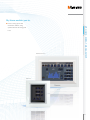
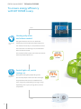

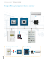
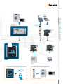


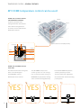
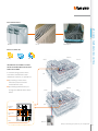
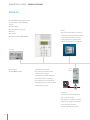
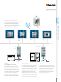
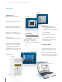
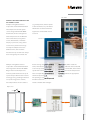
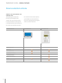
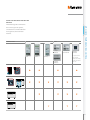
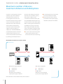
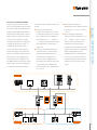
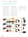
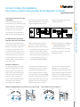
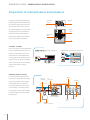
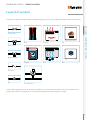
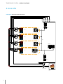
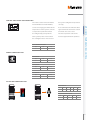
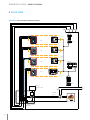
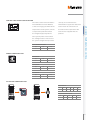
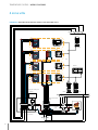
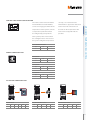
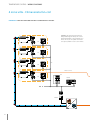
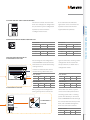
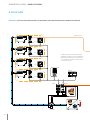
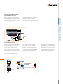
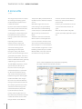
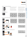
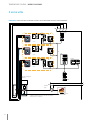
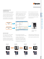
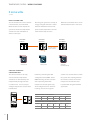
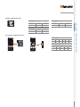
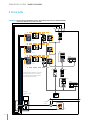
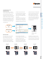
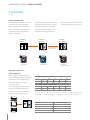

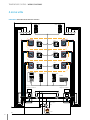
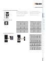
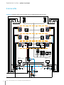

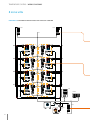
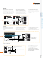
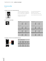
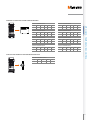
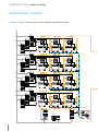
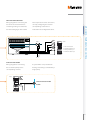
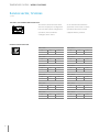
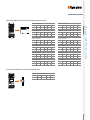
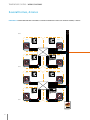
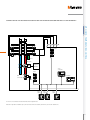
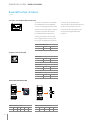
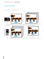
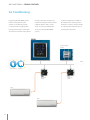
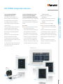

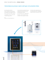
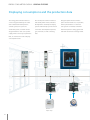
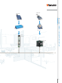
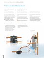
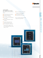


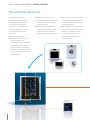
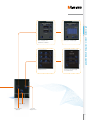
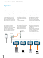
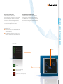
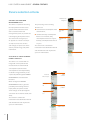
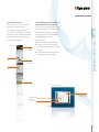
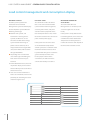
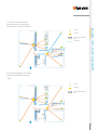
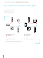
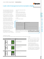
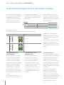
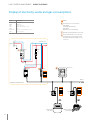
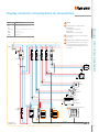
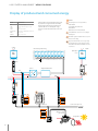
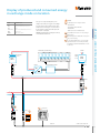
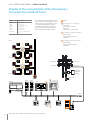
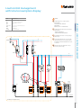
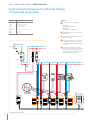
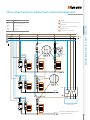


![MY HOME - Termorregulación y Climatización [pdf 8.9 MB]](http://vs1.manualzilla.com/store/data/006299556_1-14be3162ae9ed08da6bd190c5a4bbb16-150x150.png)