1
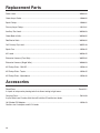
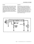
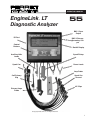
OPERATOR’S MANUAL
EngineLink LT
™
Diagnostic Analyzer
55
BNC 1 Sync
Output
I/R Port
BNC 2 PrimarySecondary Output
Control
Buttons
Backlit Display
Auxiliary Volts
Leads
Spark Pickup
Spark Can
Power Leads
Amp Probe
Coil Primary
Clip
Spark Can
Ground
KV Clips
Primary Amps
Probe
© Copyright 2005, GxT, Inc., All Rights Reserved
1
Contents
Specifications.........................................................................................................................................3
Connecting to a DIS Car........................................................................................................................4
Connecting to a Distributor Car............................................................................................................5
Connecting to a No Coil Minus.............................................................................................................6
Keys & Controls......................................................................................................................................7
Initial Setup.............................................................................................................................................7
Ignition Menu.....................................................................................................................................8-13
Ignition Primary.................................................................................................................................8-9
Ignition Secondary........................................................................................................................10-11
Hard Start...........................................................................................................................................12
Troubleshooting DIS No-Start Cars....................................................................................................12
Power Menu......................................................................................................................................13-15
Electronic Compression.....................................................................................................................13
Power Contribution.............................................................................................................................14
Power Balance - Automatic/Manual...................................................................................................15
Electrical Menu................................................................................................................................16-17
Starting/Charging History...................................................................................................................16
Volt Amp Meter...................................................................................................................................17
Auxiliary Meter...................................................................................................................................18
Zero Amp Probe.................................................................................................................................17
Sensors Menu..................................................................................................................................17-19
TPS Test.............................................................................................................................................17
O2 Sensor Test...................................................................................................................................17
Auxiliary Meter...................................................................................................................................18
Logic Trace Scope..............................................................................................................................18
Solenoid Duty Cycle...........................................................................................................................18
Injector Drive......................................................................................................................................19
Fuel Menu
Injector Drive......................................................................................................................................19
O2 Sensor Test...................................................................................................................................17
Solenoid Duty Cycle...........................................................................................................................18
Reports Menu..................................................................................................................................20-21
Run Auto-Test....................................................................................................................................20
Print Saved Data................................................................................................................................20
Visual Inspection................................................................................................................................21
Auto-Test Configuration......................................................................................................................20
Setup Menu......................................................................................................................................21-23
Engine Setup.......................................................................................................................................7
EngineLink Setup..........................................................................................................................21-23
LCD Contrast..............................................................................................................................21
Custom Header...........................................................................................................................21
Save Setup.................................................................................................................................22
System Diagnostics....................................................................................................................22
Scope Setup...............................................................................................................................22
Printing..................................................................................................................................................23
Demo Mode...........................................................................................................................................23
Typical Readings.............................................................................................................................24-25
Replacement Parts & Accessories.....................................................................................................26
Warranty & Service...............................................................................................................................27
Safety Warnings....................................................................................................................................28
2
Introduction
The EngineLink™ is a professional grade tool for diagnosing automotive ignition, fuel injection, and
electrical systems. Test DIS and Distributor engines. Diagnose problems with ignition, starting/charging
and fuel-delivery systems, as well as computer sensors and drivers. Our AutoSort feature automatically
determines coil and plug polarity on DIS engines. The Autotest function performs Ignition Primary, Ignition
Secondary, Power Tests, Starting/Charging History, and Compression Tests automatically in about 10
minutes. Power Balance and Power Contribution checks cylinder performance on DIS and Distributor
engines. Primary Amps checks coils and modules. Spark Burn and KV tests check ignition plugs and
wires. Cranking Analysis checks cylinder compression uniformity and Starting/Charging Analysis tests
Specifications
Measurement Ranges
Battery Volts......................................................................................................................... to 19.99 Volts
Volts, Aux (10 Meg)................................................................................................................. ±20.00VDC
..................................................................................................................................... to 50.0 VAC Pk-Pk
Amps, Inductive.................................................................................................................0 to ±600 Amps
Tachometer....................................................................................................................100 to 5,000 RPM
Dwell, Ignition.......................................................................................................... Degrees, %, or mSec.
Driver/Points Resistance....................................................................................................... 0 to 3.0 Volts
Dwell Variation...........................................................................................................................in Degrees
Timing Variation.........................................................................................................................in Degrees
Ignition Coil Amps...............................................................................................................0 to 19.9 mSec
Coil Amps Build Time...........................................................................................................0 to 9.9 mSec
Spark Burn Time...................................................................................................................0 to 9.9 mSec
Ignition Energy.....................................................................................................0 to 99 milliVolt-Seconds
Secondary KV...................................................................................................................0 to 32 Kilovolts
Pulse Rate........................................................................................................................... 0 to 999 Hertz
Cylinder Power Balance........................................................................................................% RPM Drop
Cylinder Power Contribution...................................................................................................Speed Index
Amps Ripple................................................................................................................. Message Indicator
Cranking Compression........................................................................................................ % Amps Peak
Injector Amps Drive Time...................................................................................................0 to 99.9 mSec
Injector Peak Amps............................................................................................................0 to 19.9 Amps
Throttle Position Sensor...................................................................................................... Glitch Catcher
O2 Sensor.................................................................................................................. Volts and Crossings
with Optional Sensors:
Diesel RPM....................................................................................................................100 to 5,000 RPM
3
Connecting to a Distributorless Ignition
Sparkwire Clips
Spark Pickup
Primary Amps Pickup
Power Leads
Amp Probe
Auxiliary Lead
SPARKWIRE CLIPS
The EngineLink™ automatically sorts negative and positive firing plugs, and figures out coil pairings.
Connect the center Sparkwire Clip to #1 Cylinder, and connect the rest of the Sparkwire Clips to any
cylinder in any order. Connect the ground lead to a good engine ground.
PRIMARY AMPS PICKUP - DIS
Put the black Primary Amps Pickup around the wire that provides 12V power (B+) to the ignition module
and all coils. You may hookup around the wire anywhere in the wiring harness, but be sure the pickup is
around the wire that carries only the ignition pulses. The pickup label must face toward the battery plus
end of the wire (away from the coil).
SPARK PICKUP
The red Inductive Spark Pickup connects about the #1 cylinder plug wire. Connect close to the plug and
at least 4 inches away from the Sparkwire Clip on #1 cylinder. The label on the Pickup should face the
spark plug.
INDUCTIVE AMP PROBE
Connect the probe around the negative battery cable with the arrow pointing away from the battery, or the
positive battery cable with the arrow pointing towards the battery.
12V BATTERY LEAD
Connect the power leads to vehicles 12 volt battery. The connection must be made at the battery.
AUXILIARY LEAD
Not a required connection. Use the Auxiliary Lead for Sensor and voltage tests.
Primary Wire Colors
Manufacturer
GM, Some 4 Cyl.
GM, All Other
Chrysler
Chrysler Imports
Ford 4 Cyl.
4
Wire Color
Pink
Pink/Black
Green/Black or Red
Black/White
Blue
Manufacturer
Wire Color
Ford, All Others
Red/Green
Hyundai
Black.White
Infiniti
Brown/Yellow
Lexus
Black/Orange
Mazda
Red/Lt. Green
Toyota
Black/Orange
Otherwise, consult the car’s service manual wiring diagram.
Connecting to a Distributor Ignition
Sparkwire Clip
Auxiliary Lead
Coil Primary Clip
Spark Pickup
Amp Probe
Power Leads
SPARKWIRE CLIPS
Disconnect all Sparkwire Clips from the Spark Can except the middle lead. Connect it to the coil wire. If
the ignition system uses an internal coil, use one of the provided KV Plates.
COIL PRIMARY CLIP
Connect to the ignition coil primary (-) terminal. Sometime labeled “TACH”, it is the signal source for the
ignition primary circuit measurements. It is necessary for ignition suppression.
SPARK PICKUP
The red Inductive Spark Pickup connects about the #1 cylinder plug wire. Connect close to the Distributor.
The label on the Pickup should face the spark plug.
INDUCTIVE AMP PROBE
Connect the probe around the negative battery cable with the arrow pointing away from the battery, or the
positive battery cable with the arrow pointing towards the battery.
12V BATTERY LEAD
Connect the power leads to vehicles 12 volt battery. The connection must be made at the battery.
AUXILIARY LEAD
Not a required connection. Use the Auxiliary Lead for Sensor and voltage tests.
KV PICKUP PLATES
Pickup plates are provided for GM, Toyota, and Nippondenso systems that have the coil located within the distributor.
To read KVs, clip the appropriate pickup plate to the distributor housing, attach a Sparkwire KV Clip to the bar or
post on the pickup plate, and plug it into either the Distributor KV Lead or the Cylinder #1 position of the DIS KV
Harness.
NOTE: The KV pickup plates are designed to be sensitive. To obtain valid readings, keep hands and wires away
from the KV Pickup Plate and the KV Clip during testing.
5
Connecting to a No Coil Minus Ignition
Sparkwire Clip
Auxiliary Lead
Coil Primary Clip
Spark Pickup
Amp Probe
Power Leads
SPARKWIRE CLIPS
Disconnect all Sparkwire Clips from the Spark Can except the middle lead. Connect it to the coil wire. If
the ignition system uses an internal coil, use one of the provided KV Plates.
PRIMARY AMPS PICKUP
Put the black Primary Amps Pickup around the wire that provides 12V power (B+) to the ignition module
and coil. You may hookup around the wire anywhere in the wiring harness, but be sure the pickup is
around the wire that carries only the ignition pulses. The pickup label must face toward the battery plus
end of the wire (away from the coil).
SPARK PICKUP
The red Inductive Spark Pickup connects about the #1 cylinder plug wire. Connect close to the distributor.
The label on the Pickup should face the spark plug.
INDUCTIVE AMP PROBE
Connect the probe around the negative battery cable with the arrow pointing away from the battery, or the
positive battery cable with the arrow pointing towards the battery.
12V BATTERY LEAD
Connect the power leads to vehicles 12 volt battery. The connection must be made at the battery.
AUXILIARY LEAD
Not a required connection. Use the Auxiliary Lead for Sensor and voltage tests.
A No Coil Minus ignition is an ignition system where the secondary ignition coil is housed in the Distributor
Cap, and the coil minus lead is not accessible. Some Toyota and Nipondenso ignitions are of this type.
6
Keys & Controls
MENU
Press the MENU key anytime you want access
to the main test menu.
MESSAGE
The MESSAGE key is active when the flashing
message symbol '* is on the screen. Messages
may span several screens. Press the MESSAGE
key until all messages have been viewed, and the
original screen has been restored.
MENU
NEXT
HELP
HELP
Press the HELP key when you want context
sensitive help.
PRINT
PRINT
Press PRINT to print the display contents to a printer.
Arrow Keys
Use the up and down arrow keys to change numbers or make a different selection.
Material: 0.010 thk Polycarbonate, Matte Finish.
NEXT
Acrylic Adhesive Backing Over All Except As Shown.
The NEXT key is used to go on to the next step in a test or procedure or to act on an item that is selected.
Print Subsurface as shown. Align Artworks to Targets.
In some cases the NEXT key will clear minimums or maximums and restart a measurement.
Label Size: 12.0" x 9.0".
Initial Setup
The setup Engine Setup screen automatically appears
after power is applied to the unit. You must program the
EngineLink with the proper information about the vehicle
to be tested. Use the up and down arrows to move the
cursor to your selection. Pressing NEXT will enter the
selection and move to the next menu.
Select the number of cylinders, and press NEXT. A new
screen will appear, offering a choice of ignition type.
Distributor ignitions will have a Separate Coil or an
Integral Coil, where the coil is inside the distributor
housing (like GM HEI). In some cases, as with many
Nippondenso ignitions, the Coil (-) wire is not accessible.
In that case, SELECT No Coil (-) Wire.
Non-Distributor ignitions include Diesel engines, DIS
Coil/Plug, and DIS Dbl End (double end or output) where
each coil fires two plugs at the same time.
Select the ignition type, and press NEXT. Select 4 or
2 strokes, and select the firing order. Choosing a firing
order causes test data to be displayed in cylinder block
number sequence. If the default is accepted, e.g., 1 2 3
4, the results will be displayed in firing order sequence.
7
Ignition Primary - DIS
This test measures the input power and response of
the coil. If there are no readings, or they are obviously
wrong, check your connections.
COMPOSITE SCREEN
RPM is read by the black Primary Amps probe from the
current pulses drawn by the ignition coils. Battery voltage
comes from the red and black Battery Clips. The next
display line shows the average ignition primary amps
and the average milliSeconds it took for all coils to build
up the current during dwell.
DRIVE MILLISECONDS
The Drive MilliSeconds reading is the total dwell time
from the time the coil begins to charge to the time of
plug firing. In current-limiting electronic ignitions, the
difference between drive and build time is the “hold”
period.
MULTISPARK
Some ignition systems spark more than once during
each power stroke. If so, the words “Multispark Ign.” will
appear with the number of sparks per ignition.
INDIVIDUAL COIL READINGS
Press the up and down arrows to see individual coil readings. The numerical screen shows Peak Amps,
Build and Drive milliSeconds per coil. Two more screens show peak amps and build milliSeconds in bar
graph format.
PEAK AMPS
Look for equal current in each ignition coil, between 4 and 11 amps. If the primary ignition supply circuit
has bad connections, all amps may be low.
BUILD MILLISECONDS
These readings are useful for checking current-regulating ignitions that take a fixed time to build coil
current. Typical build time is 3 to 4 mSec. This time is nearly constant up to about 3000 RPM, and then
begins to shorten as RPM increases. If battery voltage is low, build times will lengthen.
Build time is a function of battery voltage, the inductance of the coil primary, and the peak amps level at which
the ignition module is set to regulate. The following relationships exist, if other factors are constant.
Long build time may be caused by high resistance in the primary circuit. Remember that the coil primary
circuit includes the power feed, the coil primary, the drive module, and its connection to ground. Increased
resistance from loose or corroded connections limits the primary current. This may cause lower peak amps
or longer build time readings.
Short build time may be caused by shorted coil windings.
Build time will be slightly longer while cranking, because of reduced battery voltage. If the ignition module
is not regulating at all, then Peak Amps can be High and Build can be Long. Both will be limited only by
the primary circuit resistance and battery voltage.
8
Ignition Primary - Distributor
IGNITION ENERGY
Ignition energy is the quality of the ignition coil inductance.
This indicates the coil “kick” in milliVoltSeconds (mVSec).
The engine must be cranking or running to produce a
readable signal. Typical standard ignition coils produce
25 to 40 mVSec. High energy ignitions have 40 to 60
mVSec. Readings below 20 mVS suggest that inadequate ignition energy is being delivered by the coil.
COIL OSCILLATIONS
This is an indicator of liveliness in the ignition coil. Shorts in coil insulation or in connected components
usually dampen the oscillations so they are reduced or eliminated. Points driven ignition coils usually
show 4 to 8 oscillations, which are more than electronic ignitions that do 1 to 4. Some Chrysler ignition
modules begin dwell immediately after the spark burn, so they normally do not show any oscillations.
DRIVER MODULE / POINTS VOLTAGE
“Driver” is the voltage during the dwell time. For mechanical points it should be less than 0.3 volts.
Electronic modules typically have 0.5 to 1.5 volts. Ignitions made alike should compare within 0.2 volts.
In this test, a higher voltage indicates a failing (high resistance) coil driver output transistor, bad points,
or a high resistance connection to ground.
DWELL
Press SELECT to display dwell in degrees, percent, or milliSeconds. MilliSeconds are useful for checking
the charging time for current-limited electronic ignitions, which take a fixed time to build up the coil amps.
A typical HEI coil charges in 3.5 mS at idle RPM, and 4.5 mS while cranking.
DWELL VARIATION
This is the difference in degrees between the longest and shortest dwell period. On electronic ignitions, it
could be from an unstable coil drive module. On points ignitions, mechanical sloppiness in the distributor
shaft bearings and cam shaft drive is the prime cause. At higher speeds, on points ignitions, the problem can
be floating contacts due to weak springs and poor lubrication. Readings should be less than 3 degrees.
TIMING VARIATION
Variations in timing is the difference in engine shaft degrees of the longest and the shortest times between
ignition firings. On pre-computer engines, variation meant looseness in the mechanical drive from the
crankshaft to the points cam. Sometimes timing is intentionally varied by engine computers.
Irregular idle RPM from O2 feedback fuel metering can cause timing variation also. Operating the engine at
higher RPM should reduce the variation to under 3 degrees. Read variation from 1000 to 3000 RPM with the
RPM held steady. During acceleration or deceleration, the Timing Variation is not a valid measurement.
PRIMARY
AMPS
BUILD
mSec
COIL
PEAK
AMPS
PRIMARY
VOLTS
IGNITION TIMING CYCLE
SPARK
BURN
TIME
SPARK
LINE
0 v
DWELL SECTION
BUILD
(DWELL)
AMPS
HOLD
BATTERY
VOLTAGE
Ignition Coil Primary Current and Voltage
9
Ignition Secondary - DIS
The EngineLink will analyze the ignition and determine
the polarity of each of the KV clips. When complete,
a screen will advise that the throttle should be opened
abruptly. This sets the minimum and maximum readings.
The composite screen will appear, showing the average
readings for all coils.
SPARK BURN DURATION
The spark burn duration on a DIS is usually between 0.5
and 1.5 mSec. Long burn duration comes from narrow
or fouled plug gaps, insulation shorts, low cylinder
compression, and rich fuel mixtures. Short burn duration
is caused by breaks in ignition secondary wires, wide
spark plug gaps, worn plugs, high circuit resistance, and
very lean fuel mixtures.
A reduction in burn durations, with snap acceleration, is
an ideal check for spark plug gaps that have the sharp
edges worn off, and to see that insulation does not arc
through.
Problems like wire breaks and high secondary resistance
are most easily detected at a moderate and steady RPM
between 1000 and 2000.
FIRING KV — Live and Maximum
Firing KV is the voltage that is required to start ionizing
the air/fuel mix in the spark plug gap. For the ignition
to always work, the KV available from the coil must be
more than the highest KV requirement. Causes of high
KV can be a wide or worn plug gap, a broken sparkwire conductor, or a lean fuel mixture. Unusually low
KV can be from a fouled plug gap, secondary insulation failure, or low compression. Typical live KV is 5
to 10 at a steady RPM with not more than a 5 KV difference between the highest and lowest.
EXHAUST KV
Also known as waste KV. On double output coils, the spark plug in the cylinder on its exhaust stroke
serves as the ground path for the coil. Exhaust KV should be low because, without compression in the
cylinder, little voltage should be needed to fire the plug. Exhaust spark is normally less than 5 KV. Higher
readings indicate the possibility of a broken spark plug wire, a wide plug gap, or a fouled plug on the
opposite side.
INDIVIDUAL CYLINDER READINGS
Use the up and down arrows to see four additional screens that show data for the individual cylinders.
The burn time bar graph screen shows live spark burn time for each cylinder. The number in the upper
left corner shows the average for all cylinders. Press HELP to see an explanation of the screen. The burn
time numerical screen shows min., max., and live spark burn time for each cylinder in numerical format.
The KV bar graph screen shows live KiloVolt readings for each cylinder. The bottom of the left bar
represents the minimum kilovolts and the top is the maximum. The top of the middle bar shows the live
reading for firing KV and the right bar shows exhaust KV.
10
Ignition Secondary - Distributor
The EngineLink will advise that the throttle should be
opened abruptly. This sets the minimum and maximum
readings. The composite screen will appear, showing
the average readings for all coils.
SPARK BURN DURATION
The spark burn duration on a DIS is usually between 0.5
and 1.5 mSec. Long burn duration comes from narrow
or fouled plug gaps, insulation shorts, low cylinder
compression, and rich fuel mixtures. Short burn duration
is caused by breaks in ignition secondary wires, wide
spark plug gaps, worn plugs, high circuit resistance, and
very lean fuel mixtures.
A reduction in burn durations, with snap acceleration, is
an ideal check for spark plug gaps that have the sharp
edges worn off, and to see that insulation does not arc
through.
Problems like wire breaks and high secondary resistance
are most easily detected at a moderate and steady RPM
between 1000 and 2000.
FIRING KV — Live and Maximum
Firing KV is the voltage that is required to start ionizing
the air/fuel mix in the spark plug gap. For the ignition
to always work, the KV available from the coil must be
more than the highest KV requirement. Causes of high
KV can be a wide or worn plug gap, a broken sparkwire
conductor, or a lean fuel mixture. Unusually low KV can be from a fouled plug gap, secondary insulation
failure, or low compression. Typical live KV is 5 to 10 at a steady RPM with not more than a 5 KV difference
between the highest and lowest.
INDIVIDUAL CYLINDER READINGS
Use the up and down arrows to see four additional screens that show data for the individual cylinders.
The burn time bar graph screen shows live spark burn time for each cylinder. The number in the upper left
corner shows the average for all cylinders. Press HELP to see this and explanation of the screen. The burn
time numerical screen shows min., max., and live spark burn time for each cylinder in numerical format.
The KV bar graph screen shows live KiloVolt readings for each cylinder. The bottom of the left bar
represents the minimum kilovolts and the top is the maximum. The top of the middle bar shows the live
reading for firing KV.
The KV numerical screen shows live, maximum and exhaust KV per cylinder in numerical format:
11
Hard Start - Distributor
Use this test to find the problem area on a no-start
engine. If a Distributor ignition was selected during
Engine Setup, this screen will appear.
The ignition signal for this test comes from the Coil
Primary Clip connected to the Coil (-), TACH terminal
of the coil.
The Amps reading shows starter draw, measured by the Inductive Amp Probe. The probe should be zeroed
before testing. To zero, press NEXT and follow the on-screen instructions. Ignition Energy shows the coil's
charge level. Dwell shows coil charging time. Auxiliary Volts can be measured, using the Auxiliary Meter
Lead, to confirm that voltage is present at the ignition or to detect voltage drops in cables and connections.
Voltage at the lead, referenced to both the positive and negative battery power clips, is shown. Volts AC
P-P (peak-to-peak) can be used to check the output of pulsing type sensors. RPM and Battery Voltage
are used to measure the performance of the cranking system. Special diagnostics pick out problems with
the spark plugs, wires, cap and rotor.
Hard Start - DIS & No Coil Minus (-)
This screen is similar to the one for Distributor ignitions,
but Peak Amps and Build Time are measured instead of
Ignition Energy and Dwell.
Troubleshooting DIS No-Start Cars
This procedure will be helpful when diagnosing DIS no start cars. Do not skip any steps, and do not
perform this test until you are experienced in using the EngineLink LT. Improper connections can lead to
an incorrect diagnosis.
1. Select the IGNITION:PRIMARY test, then try to start the engine. The following readings should be
within the stated guidelines:
Battery Volts:
Should be greater than 9.6 volts. If not, diagnose and repair the starting/charging
system.
RPM:
Should be appropriate for the engine being tested.
Peak Amps:
Refer to the Typical readings section of this manual, Page 25. This will diagnose the
module, and coils. If you do not read any peak amps, check to see there is 12 volts going
to the module. If 12 volts are present, use a labscope to check the Cam/Crank Sensor.
If the sensors are good, the module is defective. If all of the above readings are good,
the coils, modules, crank and cam sensors are operating properly.
2. Check fuel pressure and volume. If the results are good, proceed to the next step.
3. Use the Fuel Injector Test on the EngineLink LT. During cranking the Peak Amps reading should
not be greater than 4 amps. If Peak Amps are greater than 4, you have located a defective injector.
Wiring diagrams for the fuel injection system on the car you are testing are an invaluable tool when
12
Electronic Compression
If a DIS ignition was selected during Engine Setup, the
EngineLink will prompt you to disable the fuel supply to
prevent the engine from starting during cranking. This
is usually done by unplugging the power wire or fuse to
the fuel injectors or fuel relay. Many late model vehicles
will disable the fuel if wide-open throttle is applied before
cranking. The engine may start unexpectedly, so be prepared to release the key and the pedal.
On a distributor engine, the EngineLink will suppress the ignition during cranking.
Ignition power must be kept on so the analyzer will sense each cylinder’s ignition pulse. Keep the vehicle’s
doors closed during the test.
Crank the engine. If the engine fires during cranking, the data will be invalid. Holding the engine intake
manifold throttle wide open will help prevent some engines from firing. Data saving will begin when cranking
is sensed.
On a distributor engine, when the ignition has been suppressed, the engine will start when the Diagnostic
Center releases the ignition suppression at the end of the cranking period, otherwise the STOP CRANKING
message will appear. On a DIS engine, or if you were prompted to disable fuel on a distributor engine, a
message will appear reminding you to restore the fuel supply. Then the results of the test will appear.
The % Max row shows the amount of cranking draw required to pull each cylinder through compression,
as a percent of the largest cylinder’s draw. One (or more) cylinders will show 100%, and the rest should
be within a few points of 100%. The % Low row shows how much below 100% each cylinder was.
If all readings from this test are within a 5% range, compression is probably within the typical gauge
specification of 75% of the highest pressure reading. If at least one reading is more than 7% lower than the
highest (% Low is greater than 7%), it is likely that there is a problem. In that case, a message may suggest
a gauge pressure test. Four-cylinder engines have good correspondence between display readings and
cylinder performance, while six cylinder engines may have overlapping readings. The readings on eight
cylinder engines overlap enough that the lowest peak reading may actually correspond to the preceding
cylinder.
Compare the results with those obtained in the Power Contribution, Power Balance and Ignition Secondary
tests. Those results, along with other symptoms, may suggest a gauge compression test to determine the
actual pressures/cylinder before extensive work is prescribed.
Note that temperature and friction of the engine affect the electrical draw. A very hot or cold engine,
or one that has new piston rings and bearings may draw higher than normal, thus tending to cover up
compression variations.
Cranking Draw readings give an indication of engine cylinder compression uniformity. This is possible
because starter battery draw is related to the cranking torque, and the cranking torque varies as cylinders
go into compression and then spring back.
On double-end DIS ignitions, it is likely that the message "Results Not in Sync" will appear. The tests
results will be accurate, but may not start with Cylinder #1. If readings are uniform, sync will not matter.
If one or more cylinders are low, a gauge test will be recommended to verify the actual compression in
each cylinder.
Redo the test when in doubt about the test results.
13
Power Contribution
This test measures each cylinder’s contribution to
the power output of the engine, without using spark
suppression. Power Contribution is not available when
Engine Setup "Ignition" is set to Diesel.
To run this test on distributor engines, the black Primary
Amps probe must be placed around the wire supplying
12 volt power to the ignition coil(s) with the label facing
toward the battery feed.
There are two screens available. Press SELECT to
change between screens. The bar graph shows relative
power contribution per cylinder. The other screen shows
the variations numerically:
This test relies upon steady timing, fixed air-fuel feed, and a constant amount of engine drag to make
cylinder comparisons. To put a steady drag on the engine, turn the heater fan on high and the headlights
on bright. Keep the engine at idle RPM. However, if idle is surging, use a throttle holder to bring it up to
1200. Low RPM gives better readings provided that RPM is stable. Putting an engine in open loop mode
may also help.
The graph suggests how cylinder power differences affect the RPM during an engine cycle.
A low power cylinder will show a
negative power difference reading.
Smooth running engines have power
difference readings less than 5. Dead
cylinders usually read more than 15.
Power
Reading
3
-10
8
-1
RPM
Cylinder
1
2
3
4
Low power cylinder problems are Sequence
associated with worn or broken
POWER DIFFERENCE WAVEFORM
piston rings, valves and valve springs,
broken head gaskets, vacuum leaks,
fuel imbalance, spark plugs and wires
and EGR problems. If a cylinder test produces a higher RPM, it may be from crossed spark plug wires,
an open intake valve, leaking EGR, or an engine computer effect.
The results of this test, if compared to the Electronic Compression and Ignition Secondary tests can provide
additional clues about the cause of poor cylinder performance.
To gain experience with typical engines, we suggest that, while you are testing a good engine, short out
a spark plug to see the effect of a dead cylinder.
The readings are taken from the RPM during each cylinder’s power stroke, and adjusted to give somewhat
similar readings for most engines. Look for consistency among cylinders. Engines with eight or more
cylinders may show a weak cylinder in a later position than actual. For example, a weak #4 cylinder could
appear as #5. Engines with particularly heavy flywheels, for their displacement, may show the effects of
a weak cylinder spread across two or three subsequent cylinders. Engines made with staggered timing
patterns will show large difference readings when they are working correctly. For example: six cylinder
14
Power Balance - Automatic/Manual
On distributor engines, power balance, or each cylinder’s
power contribution relative to the others, can be seen by
turning off the spark plugs one at a time and measuring
the drop in RPM. In Automatic mode, the Diagnostic
Center will suppress ignition to each cylinder in turn, and
will display and save the starting and ending RPM for
each. The more RPM decrease seen, the more a cylinder
must have been contributing. If all cylinders are contributing equally, RPM drops will be consistent among
cylinders. If a cylinder shows only 1/3 of the drop of the average cylinder, it should be checked further
with the other EngineLink tests. If all drops are very low, see the facing page for advice on defeating idle
compensators which may be raising idle speed in response to the suppression.
The test relies upon steady timing, fixed air-fuel feed and a constant amount of engine drag during the
test to make valid comparisons between all of the cylinders. If the RPM drifts during the test, a message
will appear, indicating the test should be run again.
A steady drag on the engine can improve the test results. Turning the heater fan on high and headlights
on bright is usually the best method. Particular attention should be directed to eliminating loads that can
turn on or off in the middle of the test such as the air conditioner compressor and radiator fan motor.
Operating the engine above the controlled idle RPM will minimize the effects of idle compensators and
put the engine at a smoother operating point. RPMs of 1000 to 2500 are suitable for the test. Listen to
the sound of the engine as suppression is applied. A large initial RPM drop is a good indicator of a strong
cylinder.
On non-computerized engines the timing, fuel mix and idle setting do not vary with time. However, active
control systems may have to be put in open-loop mode to keep the timing and fuel mixture fixed, so that
the test results do not end with minimal % Drops.
After the test, carefully restore the disengaged parts. Service codes may be set during the test, but they
will usually clear automatically after 50 to 100 starts.
Low power cylinder problems are associated with spark plugs and wires, piston rings, valves and valve
springs, vacuum leaks, fuel unbalance, head gaskets, and EGR problems. If a cylinder test produces a
higher RPM it may be from crossed spark plug wires, an open intake valve, leaking EGR, or an engine
computer effect.
The results of this test, if compared to the Electronic Compression and Ignition Secondary tests, can
provide additional clues about the cause of poor cylinder performance.
Manual Mode
Manual suppression can be used to listen for noise changes in an individual cylinder that may give clues
about the problem.
To suppress ignition in an individual cylinder, choose Manual Suppression from the POWER menu and
SELECT the cylinder you want to suppress. Press NEXT to suppress ignition to that cylinder.
15
Starting Charging History
An electrical power system test of the engine is the primary
feature of this sequenced procedure. Performance of the
alternator, battery, and starter are evaluated.
This test records battery voltage and amps while the
starter cranks the engine for 15 seconds. Then there
is a wait to check battery recovery time, followed by a
measurement of the charging current when the engine
is run at high idle.
For accurate results, turn off all lights and accessories.
Be sure the vehicle doors are closed, as the current
drawn by dome and courtesy lights is significant and may
invalidate the test results.
If a DIS or Diesel engine type was selected during
Engine Setup, the analyzer will prompt you to disable
the fuel supply to prevent the engine from starting during
cranking. Use the recommended method to disable the
engine for compression cranking tests, from the vehicle
service manual. This is usually done by unplugging the
power wire or fuse to the fuel injectors or ignition coils.
Run the engine until it quits, to verify that fuel is cutoff.
On a distributor engine, with the Coil Primary Clip connected, the EngineLink will suppress the ignition
during cranking. If, for some reason the Diagnostic Center has difficulty suppressing a particular ignition,
the disable fuel prompt will appear.
Begin cranking when prompted. After 15 seconds, the analyzer will prompt you to stop cranking and turn
the ignition key off. (If the battery voltage drops below 9.6 volts during the test, it is too low to continue,
and the test will be aborted before 15 seconds have passed.)
When the operator stops cranking, a waiting period begins while voltage recovery time of the battery is
checked. Good batteries will spring back in 1 or 2 seconds. Worn out or undercharged batteries need
over 10 seconds to recover. Make sure all battery drains such as dome lamps are off during this test.
Keep doors closed.
Restore fuel or ignition power, as necessary, and be ready to start the engine when prompted. Run the engine
over 1500 RPM to ensure the regulator has “kicked in”, so that charging current can be measured.
The Diagnostic Center will then prompt you to SELECT a temperature range to be used in the calculation
of the battery’s Cold Cranking Amp (CCA) rating. Choose the temperature of the battery electrolyte, which
may be different from shop temperature if the battery has recently been brought in from a very hot or very
cold environment just prior to testing. The results are then displayed on this screen. Use the message
and select keys to display all measurement screens.
16
Volt Amp Meter
Amps are measured by the Inductive Amp Probe.
Battery voltage is measured at the Battery Power Clips.
Auxiliary volts are read with the Auxiliary Meter Lead and
referenced to either Battery Power Clip. Press SELECT
to change the reference between POS and NEG. Large
digits are displayed for enhanced readability. If excessive
alternator ripple is detected a message signal will appear on the display. Press the MESSAGE key to
display the text.
Zero Amp Probe
Whenever zeroing of the amp probe is desired, select this
function. A prompt will remind you that the amp probe
should be disconnected. The menu will reappear a few
seconds after a successful zero.
TPS Test
This is a computer aided test to check for glitches in
a position sensor signal. When a position sensor on a
throttle or air flow vane is moved from the rest position
to the top, the output voltage should move just like the
position shaft. A dedicated glitch detector operates
continuously and is not dependent upon sample rate.
Connect the Auxiliary Meter Lead to the throttle position sensor output wire. Switch the ignition key to the
ON position. The test screen will appear with a prompt to move the sensor slowly through its range.
Slowly move the sensor shaft through its full range. Using the voltmeter display, check that the output
responds to a typical range of 1 to 4 volts. If glitches are detected, arrows will appear in place of the
prompt, showing the voltage location of each glitch. Recheck the sensor for intermittent faults near the
indicated problem voltages. The arrows can be cleared by pressing the NEXT key.
O2 Sensor Test
Connect at the sensor harness plug or ECM. Do not
penetrate wire insulation where moisture could cause
corrosion or electrical leakage to ground.
Voltage from the vehicle O2 sensor is monitored for
crossings per second through the stoichiometric point
(0.45v), indicating rich and lean conditions. Recent
minimums and maximums are shown and used to
generate a graph. The number of crossings per second
indicates the activity level of the system. When the signal
is active (more than 2 crossings per second), the percent
of time in the rich zone is given.
Typical cross count readings for warm engines running
at a steady fast idle are in the 1 to 3 range. Low rates may indicate a damaged O2 sensor. Multiports
usually cross count fastest, and carbureted engines the slowest.
17
Auxiliary Meter
This general purpose meter is useful for measurement
of a variety of voltages and sensor signals.
Connect the Auxiliary Meter Lead to a voltage or sensor
output. Readings are referenced to the negative vehicle
battery terminal through the analyzer’s Battery Clip leads.
The DC voltage range is 0 to ±20 volts, with 0.01 volt
resolution, and a 10 megohm input impedance. AC signals up to 50 volts peak-to-peak can be measured.
Hertz up to 999 and duty cycle % are also displayed.
This test screen shows all components of a measured signal simultaneously. The meter is quite sensitive,
so while measuring a DC voltage, you may also see stray AC signals displayed as Volt P-P and Hertz.
These stray signals can be ignored and will not interfere with measurement of an AC signal to which you
are directly connected.
For greater readability from a distance, a large digit display is available by pressing the up or down
arrow.
Logic Trace Scope
Use the logic trace to observe regular or intermittent
pulses on wires for accessories, sensors, lamps,
solenoids, slow computer codes, or other on/off electrical
signals. Press NEXT to adjust the scan rate. Press
SELECT to set the threshold between -20 and +20 volts
DC. Press RECORD to freeze and display a copy of a
particular trace. The copy can then be viewed without motion, separate from the live display.
The logic trace scope displays a line trace, showing voltage transitions through a specified threshold. The
actual voltages are displayed in the upper right hand corner of the display. The threshold must be set to a
voltage that is within the range of voltage change for transitions to appear, otherwise a straight line trace
will show.
Solenoid Duty Cycle Test
Use Solenoid Duty Cycle to measure mixture controlled
carburetors, or frequency output sensors such as some
pressure and air flow sensors. Also use this test to check
Hall-effect switches.
The term “Duty Cycle” means the portion of time that
the signal is switched to ground, which is when power
is applied to solenoids, etc. Duty cycle should be constant within a few %, and is usually about 50%.
Hz for some sensors will vary directly with RPM. MC solenoid frequency should be constant, around 8-10
Hz. The up and down arrow keys will change the scaling of the “DUTY” reading to either: milliSeconds,
Percent ,or degrees / 60°
The upper right reading shows the longest and shortest duty. If the numbers match, the duty is steady. If
there is a difference, the signal pulse width is varying which may mean that there is active control (closed
loop), or if it should not vary it could be a defective signal source or connection.
18
Fuel Injector Drive Test
No readings will be displayed if there are no amps pulses,
or if the pickup is reversed, or around both wires of an
injector.
Peak Amps (PkAmp) shows the peak current driving
the injector. It is regulated by the driver. Typical peak
readings for one injector are 4 amps for current regulated
drivers, and 0.7 amps for resistance limited drivers. Compare one driver bank to another.
Build Time, or ramp time in milliSeconds (mS) is affected by the solenoid and the pintle movement. Slightly
shorter-than-normal Build Time can be caused by a solenoid winding short or an injector that is stuck.
Slightly longer could be from a bad driver or wire connection. Typically, build time is 1.3 mS.
Pulse Width is shown on the lower display line. It lets you see if the injector is actively driven. Use
momentary wide open throttle to see the Min and Max range. The center reading shows what is presently
happening. The NEXT key clears the Min and Max so they can begin accumulating again.
FUEL INJECTION CIRCUIT TYPES
Sequential - Each injector has a separate driver and can be driven independently of the other injectors.
The build time currents can overlap on these systems; for valid readings check each injector separately.
Pairs - There is one driver for each pair of injectors. The current readings, as measured through the
common supply wire, will be twice the reading expected for a single injector.
Banks - Half of cylinders are driven alternately. The current readings as measured through the common
supply wire will be 2, 3, or 4 times the reading expected for a single injector.
Fuel Injection Troubleshooting Chart
Amps
Build
Sequential
None
None
Open circuit, check continuity
Low
Long
Wiring, connections, or driver
High
Short
Shorted Winding
Amps
Build
Banked or Paired
None
None
Open circuit or bad driver
High
-------
Shorted winding
Normal
Short
Shorted winding, Driver OK
High
Long
Driver not Limiting
Low
Long
Open, high resistance, or
bad driver
Fuel Injector Hookup
19
Run Auto-Test
The AutoTest is one of the best and fastest ways to
collect comprehensive engine performance data. The
analyzer will customize the AutoTest based on the
ignition type selected during Engine Setup.
The AutoTest sequence steps through the Starting/
Charging History, Ignition Primary, Secondary, and Power Balance tests, and finishes with the Electronic
Compression test. Each of the tests is described in detail in the Engine Testing section of this manual,
and can be run individually at any time.
Make sure the engine is warmed up and running, and that all necessary test leads are connected. Enter
the AutoTest, as described above, and follow the instructions. You will be prompted to perform a variety of
actions during the test sequence, like cranking the engine during the Starting/Charging History or pressing
the NEXT key to continue a test after an action is performed. The EngineLink will do the rest, and will
print a detailed report at the end of the test.
Auto-Test Configuration
You may choose what tests you want to make up and
an Autotest.
The first screen allows you to choose the tests that you
want to run for a Distributor Engine. Use the Arrow
buttons to move the selection arrow to the test you want
to be part of the Autotest. Press NEXT to make the
selection and move to the second screen
Use the Arrow buttons to move the selection arrow to
the test you want to be part of the Autotest. Press NEXT
to make the selection. A check mark will appear next to
the tests what will be included in the Autotest.
Once you are done, press the MENU key to save the changes.
Print Saved Data
Whenever a test is run, individually or as part of an
AutoTest, the results are saved for review and printout.
The resulting printed report will include the most recent
test readings along with any generated diagnostic
messages. If no tests have been done, a message will
advise that no data is available for printing. Disconnecting
power will erase all saved data.
20
Visual Inspection
To help inform the car’s owner of additional service items
that deserve attention, the condition of many items, from
tires and fan belts to wiper blades and lamps, can be
indicated on the Visual Inspection Report. This report
is also available as part of the AutoTest.
Use SELECT to move the cursor between categories. Press NEXT to see list of items in a category. Then
use SELECT to choose one of three line endings, OK, LOW or BAD. Press NEXT to accept and move to the
next item. A check mark will appear to the left of each category that has selected items. SELECT “Return
to MENU” to return to the category list. SELECT “Print”, and press NEXT to generate the report.
LCD Contrast
LCD Contrast
Choose from four levels of display contrast for best
viewing. Contrast choice may vary with lighting and
temperature.
Custom Header
This function provides a way to place a four line
header on printed reports.
MAKING A CUSTOM HEADER
Up to four lines of header information can be entered.
The header is created in the top two lines of the screen.
The bottom two lines contain the characters that may be used in the header and the control characters.
There are two cursors. The Placement Cursor is the flashing box that indicates where the next character
will be placed. The Selection Cursor is the flashing underline. The arrows are control characters used to
move the placement cursor on the header lines, and are not printable.
Use the arrow keys to move the Selection Cursor to one of the arrows, and press NEXT to move the
Placement Cursor left, right, up or down. To show the remainder of the header, use the up and down
control characters to move the Placement Cursor to the next line.
Use the arrow keys to move the Selection Cursor under the character that you want to add. Pressing the
NEXT key places the character in the header at location of the Placement Cursor. The Placement Cursor
then moves one position to the right. The arrow keys may be held to move rapidly among the character
choices. The NEXT key may be held to rapidly place many copies of the same symbol or, in the case of
arrows, to rapidly repeat the selected movement.
When the header is completed, it must be saved. Selecting the special control character ' ', and pressing
NEXT saves the header in memory and returns to the main menu. If any other test key is pressed before
selecting the save symbol, the header will not be saved.
CHANGING THE HEADER
Select the CUSTOM HEADER function in the EngineLink Setup menu. Move the Placement cursor to the
position of the character you want to change. Choose the new character, and press NEXT. The placement
cursor will move one position to the right, ready for placement of the next character.
21
Save Setup
This option allows the most frequently used engine
setup to be saved in permanent memory. The saved
setup will be loaded whenever power is applied to the
Diagnostic Center.
System Diagnostics
Built-in tests allow you to check the operation of various
test leads. Select the lead to be tested and follow the
screen instructions.
Scope Setup
The Scope Setup function refers to the two BNC connectors located on
the back of the analyzer. BNC-1 will always send out a Sync pulse that
is sensed by the Spark Pickup. BNC-2 will output Secondary Ignition from the KV input or the Primary
Amps from the Black Pickup. The choice is determine by the Scope Setup Software.
You may use either of the signals or both to drive a labscope. Below are a couple of samples of patterns
on different labscopes.
You may also use the BNC-1 signal to trigger the labscope. This will allow you to reference any other
signal to engine rpm.
Secondary Ignition
on Labscope
22
Secondary Ignition
on Labscope
Fuel Injection Current
on Labscope
Printing
The EngineLink supports printing to a custom thermal printer. Connections for power and data are made
through the RJ-45 connector found on the back of the analyzer. Simply plug in the printer and press the
PRINT button on the front panel.
Individual test results or the autotest results can be printed.
Demonstration Mode
The EngineLink has a demonstration mode built in. If you are trying to demonstrate the unit in order to
make a sale, or you just want to get familiar with the screens without connecting to a car, the demonstration
mode will help. All the demonstration mode does is load data into the test screens. You do not actually
“run” a test in demo mode, you only see the results of the test.
To enter Demo Mode hold the Up Arrow button down as you apply power. If the analyzer says it remembers
a previous setup, press NEXT, then continue holding down the Up Arrow button. The screen will be blank
for a few seconds, then the screen will fill with information. Let go of the UP Arrow button. When you
get the screen saying there is an error printing to the printer, press the NEXT button once, then hold it
down. After a few seconds the analyzer will beep rapidly 6 times. This is your indication that the demo
has loaded successfully. Press the MENU button and view any test you like.
23
Typical Readings - Distributor
POWER
BAL & CONT.
STARTING / CHARGING
HISTORY
IGNITION
SECONDARY
IGNITION
PRIMARY
CHARGING
HARD
START
The readings listed here are typical for many common engines, but should be compared to the manufacturer's
specifications before extensive repair work is undertaken.
24
Measurement
Typical Readings
Interpretation
Battery Volts
(Engine Off)
12.4 to 12.8 Volts
Checks battery state of charge.
Below 12.3V, charge is low, or load may be on.
Ignition Energy
(Cranking)
More than 20 mVSec
Shows that there is coil energy available to
start the engine.
Battery Volts
(Engine Running)
13.2 to 15.2 Volts
Shows the voltage regulator setting and
if the alternator functions.
Amps Ripple
(Engine Running)
None
If alter nator has a bad diode or stator,
a message will appear.
Ignition Energy
(Engine Running)
35-55 mVSec
Checks for faulty coils, and driver modules.
Dwell
(Engine Running)
60% w/ Ballast
Adjust as necessary.
Dwell Variation
(Engine Running)
3.0° or less
Checks primary ignition system performance. Test from Idle to Cruise RPM.
Timing Variation
(Engine Running)
3.0° or less
Shows ignition timing irregularity if too high.
Driver Voltage
(Engine Running)
Electronic less than 1.5V
Points
less than 0.3V
S h ow s c o i l d r i ve r m o d u l e, a n d m o d u l e
ground resistance if too high.
Coil Oscillations
(Engine Running)
Electronic 1 to 4 Osc
Points
4 to 8 Osc
C h e ck s fo r s h o r t s i n c o i l i n s u l a t i o n o r
connected components.
3 to 4 mSec, current limited Checks ignition modules.
Firing KV
8 to 15 KV
Checks plug gaps and wire condition.
Burn Time, Live
ignition
0.8 to 2.3 mSec
(Engine at Idle)
Checks condition of secondary
system. Finds open or grounded spark
plug wires.
Burn Time, Minimum
(Accelerate Engine)
More than 0.8 mSec
Shows wor n or wide gap plugs, breaks
in spark plug wires, or lean fuel, if less.
Burn Time, Maximum
(Accelerate Engine)
Uniform among cylinders
Finds fouled or grounded plugs or wires.
Locates ignition misfires. Rich fuel mix.
Cranking Volts
Not less than 9.6 volts.
C h e ck s b a t t e r y a n d s t a r t e r c o n d i t i o n ,
performance. Cranking Amps
100 to 300 Amps
High amps, possible bad starter. Low amps, possi bl e bad connecti ons,
or bad battery.
Cranking RPM
Over 150 RPM
Checks starter performance.
Alternator Amps
50 to 100 Amps
Compare alternator output to specs.
Battery CCA est.
500 to 1000 CCA
Compare to Battery
Specs.
If lower than the rating on the batter y,
the batter y is weak and may be ready
for replacement.
Amps Peak
Less than 5 percent
Probably low compression, if more
than 8%.
Power Difference
per Cylinder
All cylinders should be
less than 5.
If one or more cylinders are high, compare
to the Electronic Compression and
Secondary tests.
%RPM drop when
each cylinder is
shut off
5 to 15% uniform
The higher the number the stronger
the cylinder. A negative number means
the speed increased.
Typical Readings
The primary readings listed below are for your convenience, and are the result of our own
Field Testing. Variations of ±10% should be considered normal. We strongly suggest you
test some known good vehicles to get a feel for the readings. Refer to previous page for
Starting/Charging and Power test readings, which are the same for DIS and Distributor
engines.
Company/Engine
General Motors
2.0L - I4
2.2L - I4
2.3L - I4 (Quad 4)
Other DIS 4 Cylinders
3.0L - V6
3.1L - V6
3.8L - V6 (Type I)
3.8L - V6 (Type II)
Other DIS 6 Cylinders
_________________
_________________
IGNITION
SECONDARY
IGNITION
PRIMARY
Saturn
1.9L - I4
_________________
Amps
Peak
8.0
9.0
8.0
9.0
6.5
10.0
7.0
9.5
9.0
___.__
___.__
Build
mSec
3.0
3.0
2.5
3.1
3.8
2.8
3.8
3.0
3.1
___.__
___.__
7.6
___.__
3.3
___.__
Company/Engine
Ford Motor Company
1.9L - I4
3.0L - V6
3.8L - V6
4.0L - I6
4.0L - V6
4.6L - V8
_________________
_________________
Amps
Peak
5.0
5.0
5.0
5.0
5.8
5.5
___.__
___.__
Build
mSec.
3.1
3.5
3.5
3.5
3.6
3.3
___.__
___.__
Chrysler Corporation
3.3L - V6
3.5L - V6
3.8L - V6
_________________
_________________
5.0
5.0
5.7
___.__
___.__
4.0
4.0
3.8
___.__
___.__
Measurement
Typical Readings
Interpretation
Primary Amps
More than 4, uniform
among coils.
If all are low, check primary circuit connections.
If one is low, check module.
Build Time
3-4 mSec, uniform
among coils.
If longer, check module and connections.
If shorter, check coil.
Firing KV
5 to 10 KV at steady
RPM with no more than
5 KV difference among
cylinders.
If higher, wide gap, broken wire, or lean fuel mix.
If low, fouled plug, secondary insulation failure,
o r
l o w
c o m p r e s s i o n .
Exhaust KV
Less than 4 KV.
If higher, check for wide gap or broken sparkwire,
or fouled plug on opposite side.
Burn Time
Uniform among cylinders If shorter, check for breaks in secondary wires,
If longer, check for fouled gaps or insulation
shorts.
25
Replacement Parts
Power Lead..................................................................................................................................W004-02
Green Amps Probe.......................................................................................................................X000-02
Spark Pickup................................................................................................................................X008-01
Primary Amps Pickup...................................................................................................................X012-01
Auxiliary Test Lead.......................................................................................................................W020-03
Green Bed of Nails......................................................................................................................W020-85
Red Bed of Nails..........................................................................................................................W020-82
Coil Primary Clip Lead.................................................................................................................W055-40
Spark Can....................................................................................................................................X020-42
KV Leads.....................................................................................................................................W020-42
Extension Harness (Four Wire)...................................................................................................W055-02
Extension Harness (Single Wire).................................................................................................W000-03
KV Pickup Plate - GM HEI............................................................................................................X020-44
KV Pickup Plate - Toyota..............................................................................................................X020-45
KV Pickup Plate - Nipondenso.....................................................................................................X020-46
Accessories
FerretClaws...............................................................................................................................Ferret 911
A 4 pack of unique wire piercing tools that allows testing in tight areas.
Carrying Case............................................................................................................................. G014-09
A nylon brief case 5 inches thick that will hold the 55 and the test leads.
10 Cylinder DIS Adapter...............................................................................................................X020-43
Contains two Y adapters and 2 KV Leads.
26
Technical Support & Service
Questions or inquiries about service can be answered by contacting GxT, Inc., at:
Toll Free (800) 627-5655. Fax: (231) 627-2727, or [email protected]
When sending an item to the factory address it to:
GxT, Inc., 520 MM Riggs Drive., Cheboygan, MI 49721-1061
Include a note describing the problem.
Warranty
FERRET BRAND LIMITED PRODUCT WARRANTY
GxT, Inc. of Cheboygan Michigan, warrants to the original purchaser that FERRET brand products are free from defects in materials and workmanship for a period of two years from date of
purchase. Our sole obligation for a product within the above warranties will be to repair or replace, at our option, any defective parts and return the product to the sender within the U.S.A.,
shipping prepaid, if it is sent to our Repair Department shipping prepaid and accompanied by
proof of purchase.
This Warranty does not apply to products which have been altered outside the factory; or repaired
by anyone other than the factory or its authorized service centers; or which have been damaged
from accidents, negligence, or abuse; or have been used differently than described in the printed
instructions. Please note that wear and tear on leads and replacement of consumable items such
as: NOx Sensors, Oxygen Sensors, and paper, is not covered by warranty.
GxT Inc.’s sole liability and buyer’s exclusive remedy is limited to repair or replacement of the
product as stated in the Limited Product Warranty. THERE ARE NO OTHER WARRANTIES
EXPRESSED OR IMPLIED INCLUDING THOSE OF MERCHANTABILITY OR FITNESS FOR
A PARTICULAR PURPOSE AND GxT, INC. SHALL NOT BE LIABLE FOR INCIDENTAL OR
CONSEQUENTIAL DAMAGES ARISING FROM THE SALE OR USE OF THE PRODUCT.
Some states do not allow limitations on the length of implied warranties nor exclusion or limitations of incidental or consequential damages, so that the above limitations and/or exclusion may
not apply to you.
27
SAFETY PRECAUTIONS
—Read All Instructions Before Using The Meter—
•
Always wear eye protection when testing vehicles. Be extra careful near batteries and moving parts.
Do not lay tools on a battery.
•
Battery gas is highly explosive.
a. If a battery explodes flush the acid away from persons skin with generous amounts of water.
Follow up with a neutralizing solution of baking soda and then more water.
Treat clothing, vehicle parts, and equipment similarly. Any acid traces inside equipment must
be removed by generous rinsing. Dry equipment and place in a warm 50°C (120°F) oven until
thoroughly dry.
b. Never use a wrench on the ungrounded battery terminal until the grounded one has been
disconnected. Contact between the vehicle body metal and the hot terminal can cause sparks
to ignite gas or even weld tools into a battery short circuit.
c. Keep the space around a battery well ventilated.
d. Do not make sparks or allow flames near batteries.
•
Before working on a vehicle set the brakes and block the wheels. Beware of automatic parking brake
releases.
•
Keep your work area well ventilated and free of exhaust. Engine exhaust contains deadly poisons.
Treat Gas Detector exhaust and drain hoses the same as the vehicle tailpipe. Both give off deadly
exhaust fumes.
•
Avoid electrical shocks caused by getting close to live ignition wires or touching the coil TACH terminal.
A person’s reaction near a live engine can be more damaging than the shock.
•
Keep spark producing devices at least 0.5m (18”) above the floor to reduce the hazard of igniting
gasoline vapor.
•
Do not let test leads wind up in a moving fan or pulley. Route leads away.
•
Remove finger rings and metal wrist bands. They can short terminals and become very hot from
electric current.
E055-01G
28