1
Regulatory compliance information
This product complies with the essential requirements of the following applicable European Directives, and
carries the CE marking accordingly:
The Low Voltage Directive 73/23/EEC, amended by 93/68/EEC
The EMC Directive 89/336/EEC, amended by 93/68/EEC
To obtain Declaration of Conformity, please contact your local Agilent Technologies sales office, agent or
distributor.
MANUAL CHANGES
4284A
MANUAL IDENTIFICATION
Model Number: 4284A
Date Printed: January 2000
Part Number: 04284-90040
Precision LCR Meter
Operation Manual
This supplement contains information for correcting manual errors and for adapting the manual to newer instruments that contains
improvements or modifications not documented in the existing manual.
To use this supplement
1. Make all ERRATA corrections
2. Make all appropriate serial-number-related changes listed below
SERIAL PREFIX OR NUMBER
CHANGES
ALL
MAKE MANUAL
SERIAL PREFIX OR NUMBER
CHANGES
MAKE MANUAL
1
K New Item
ERRATA
CHANGES 1
CHANGE 1 contains the information needed to adapt the 4284A’s manual.
MODEL 4284A PRECISION LCR METER OPTION 201 HANDLER INTERFACE
OPERATION NOTE
Page 2-6 Signal Line Used for List Sweep Comparator Function.
Change the description as follows:
l Comparison Output Signals:
/BIN1 - /BIN9 and /AUX_BIN indicate IN/OUT judgements for each sweep point
(refer to Figure 2-4). /OUT_OF_BINS indicates pass/fail judgement (one or
more failed judgements of Steps 1 to 10 occurred during a single sweep)
NOTE
Manual change supplement are revised as often as necessary to keep manuals as current and accurate as possible. Agilent Technologies
recommends that you periodically request the latest edition of this supplement. Free copies are available from all Agilent Technologies offices.
When requesting copies, quote the manual identification information from your supplement, or the model number and print date from the title
page of the manual.
Date/Div: January 2000/33
Page 1 of 2
PRINTED IN JAPAN
Page 2-7 Table 2-2. Contact Assignments for List Sweep Comparator Function
Change a part of the table 2-2 as follows:
Pin No.
1
2
3
4
5
6
7
8
9
11
10
Signal Name
/BIN1
/BIN2
/BIN3
/BIN4
/BIN5
/BIN6
/BIN7
/BIN8
/BIN9
/AUX_BIN
/OUT_OF_BINS
Description
Failed (out of limit) at sweep Point 1
Failed (out of limit) at sweep Point 2
Failed (out of limit) at sweep Point 3
Failed (out of limit) at sweep Point 4
Failed (out of limit) at sweep Point 5
Failed (out of limit) at sweep Point 6
Failed (out of limit) at sweep Point 7
Failed (out of limit) at sweep Point 8
Failed (out of limit) at sweep Point 9
Failed (out of limit) at sweep Point 10
/OUT_OF_BINS is asserted when one or more
fail judgements of Step 1 to 10 occur in
a single sweep.
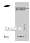
Page 2-8 Figure 2-4. Signal Area Example. (For The List Sweep Comparator Function)
Change the figure as follows:
MANUAL CHANGES
4284A
MANUAL IDENTIFICATION
Model Number: 4284A
Date Printed: January 2000
Part Number: 04284-90040
Precision LCR Meter
Operation Manual
This supplement contains information for correcting manual errors and for adapting the manual to newer instruments that contains
improvements or modifications not documented in the existing manual.
To use this supplement
1. Make all ERRATA corrections
2. Make all appropriate serial-number-related changes listed below
SERIAL PREFIX OR NUMBER
CHANGES
All
MAKE MANUAL
SERIAL PREFIX OR NUMBER
CHANGES
MAKE MANUAL
1
K New Item
ERRATA
CHANGES 1
CHANGE 1 contains the information needed to adapt the 4284A’s manual.
Changed the company name from YOKOGAWA-HEWLETT-PACKARD, LTD., or its abbreviation YHP to Agilent
Technologies Japan, Ltd.
NOTE
Manual change supplement are revised as often as necessary to keep manuals as current and accurate as possible. Agilent Technologies
recommends that you periodically request the latest edition of this supplement. Free copies are available from all Agilent Technologies offices.
When requesting copies, quote the manual identification information from your supplement, or the model number and print date from the title
page of the manual.
Date/Div: January 2000/33
Page 1 of 3
PRINTED IN JAPAN
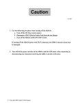
The pink sheet titled “CAUTION ON OPERATION”
Change the page title as follows.
CAUTION ON OPERATION
3.HANDLER INTERFACE BOARD (OPTION 201)
Add the following information.
Fuse: Non Time Delay 0.5A 125V
If you need this fuse,contact your nearest Agilent Technologies Sales and Service Office.
Dangerous voltage may be present in the 4284A even through the power
switch is off. Be sure to wait 1 minutes for the internal capacitors to
discharge.
MODEL 4284A PRECISION LCR METER OPTION 201 HANDLER INTERFACE
OPERATION NOTE
Page 2-16 Procedure 1 and Warning
Change the procedure 1 and warning as follows:
1.
Disconnect the power cable from the 4284A and allow 1 minute for the internal capacitors to
discharge.
Dangerous energy/voltage exists when the 4284A is in operation,and for a
time after it is powered down. Allow 1 minute for the internal capacitors to
discharge.
Page 2-17
Add the following CAUTION after the procedure 7.
The interface board contains electronic components that can be damaged
by static electricity through electrostatic discharge(ESD).To prevent ESD
damage,maintain frequent contact with any bare sheet metal surface on the
chassis. A grounding wrist strap (or similar device) is useful for this
purpose. Handle the board carefully at all times. Avoid touching electronic
components or circuit paths.
MODEL 4284A PRECISION LCR METER OPTION 202 HANDLER INTERFACE
OPERATION NOTE
Page 3-4 Procedure 1 and Warning
Change the procedure 1 and warning as follows:
1.
Disconnect the 4284A’s power cord and allow 1 minute for the internal supply filter capacitors to
discharge.
Dangerous energy/voltage exists when the 4284A is in operation,and for a
time after it is powered down. Allow 1 minute for the internal capacitors to
discharge.
Page 3-4
Add the following CAUTION after the procedure 6.
The interface board contains electronic components that can be damaged
by static electricity through electrostatic discharge(ESD).To prevent ESD
damage,maintain frequent contact with any bare sheet metal surface on the
chassis. A grounding wrist strap (or similar device) is useful for this
purpose. Handle the board carefully at all times. Avoid touching electronic
components or circuit paths.
MODEL 4284A PRECISION LCR METER OPTION 301 SCANNER INTERFACE
OPERATION NOTE
Page 2-11 PROCEDURE 1 and Warning
Change the procedure 1 and warning as follows:
1.
Disconnect the power cable from the 4284A and allow 1 minute for the internal capacitors to
discharge.
Dangerous energy/voltage exists when the 4284A is in operation,and for a
time after it is powered down. Allow 1 minute for the internal capacitors to
discharge.
Page 2-12
Add the following CAUTION after the procedure 7.
The interface board contains electronic components that can be damaged
by static electricity through electrostatic discharge(ESD).To prevent ESD
damage,maintain frequent contact with any bare sheet metal surface on the
chassis. A grounding wrist strap (or similar device) is useful for this
purpose. Handle the board carefully at all times. Avoid touching electronic
components or circuit paths.
Agilent 4284A Precision LCR Meter
Manual Change
Agilent Part No. 04284-90041
September 2004
Printed in Japan
Change 1
Change “|Z|, |Y|, L, C, R, X, G, and B Accuracy” on page 9-8 as follows:
|Z|, |Y|, L, C, R, X, G, and B Accuracy
|Z|, |Y|, L, C, R, X, G, and B accuracy Ae is given as
Ae A Ka Kaa Kb Kbb Kc 100 Kd Ke
A:
Ka:
Kaa:
Kb:
Kbb:
Kc:
Kd:
Ke:
[%]
Basic Accuracy (Refer to Figure 9-4 and 9-5.)
Impedance Proportional Factor (Refer to Table 9-1.)
Cable Length Factor (Refer to Table 9-2.)
Impedance Proportional Factor (Refer to Table 9-1.)
Cable Length Factor (Refer to Table 9-3.)
Calibration Interpolation Factor (Refer to Table 9-4.)
Cable Length Factor (Refer to Table 9-6.)
Temperature Factor (Refer to Figure 9-6.)
L, C, X, and B accuracy applies when Dx (measured D value) ≤ 0.1.
R and G accuracy applies when Qx (measured Q value) ≤ 0.1.
When Dx > 0.1, multiply Ae by
When Qx > 0.1, multiply Ae by
1 Dx for L, C, X, and B accuracy.
1 Qx for R and G accuracy.
2
2
When measured value < 10 mΩ, |Z|, R, and X accuracy Ae is given as
Ae Ka Kaa Kc 100 Kd Ke
[%]
Ka:
Impedance Proportional Factor (Refer to Table 9-1.)
Kaa:
Cable Length Factor (Refer to Table 9-2.)
Kc:
Calibration Interpolation Factor (Refer to Table 9-4.)
Kd:
Cable Length Factor (Refer to Table 9-6.)
Ke:
Temperature Factor (Refer to Figure 9-6.)
X accuracy applies when Dx (measured D value) ≤ 0.1.
R accuracy applies when Qx (measured Q value) ≤ 0.1.
When Dx > 0.1, multiply Ae by
When Qx > 0.1, multiply Ae by
1 Dx for X accuracy.
1 Qx for R accuracy.
2
2
Change 2
Add the following description to “4284A Calibration Accuracy” on page 9-16.
When measured value < 10 mΩ, calibration accuracy Acal is given as
follows:
0.03 [%] *
20 Hz ≤ fm ≤ 1 kHz:
1 kHz < fm ≤ 100 kHz:
0.05 [%] *
100 kHz < fm ≤ 1 MHz:
0.05 + 5 fm 10 –5 [%] *
fm : test frequency [kHz]
* Acal = 0.1% when Hi-PW mode is ON
Change 3
Add 42030A (1 Ω) to Recommended Model column for Standard Resister in Table 10-1 (page
10-3).
Change 4
Add the following steps to the impedance measurement accuracy test (between step 29 and 30,
page 10-17).
a. Set the measurement function to R-X.
b.
Connect the 1 Ω standard resistor to the 1 m Test Leads (16048A).
c.
Perform Step d through e for all the test listed in Table 10-9-a.
d.
Press the TRIGGER key.
e. Confirm the 4284A's reading is within the test limits in Table 10-9-a.
Table 10-9-a. Impedance Measurement Accuracy Test Limits for 1 m Cable Length
Operation
Setting
Test Limits (R)
Signal Level
Test Frequency
Measurement Range
1Ω Standard
510 mV
1 kHz
10 Ω
C.V. ± 0.0026 Ω
5.1 V*
1 kHz
1Ω
C.V. : Standard's calibration value at DC
* Option 4284A-001 only
Change 5
Change Impedance Measurement Accuracy Test Limits as follows.
C.V. ± 0.0030 Ω
Table 10-7 “Impedance Measurement Accuracy Test Limits (1 of 2)” at page 10-14.
Signal Level: 510 mV
Test Frequency: 20 Hz
Parameter: D
1000 pF Standard
Wrong limit: ・0.00319
Correct limit: ・0.03190
Change 6
Change Performance Test Record for Impedance Measurement Accuracy Test as follows.
Performance test record for 100 pF Standard at page 10-42
OSC Level: 510 mV
Change 125 Hz Cp MINIMUM test limit as below
Wrong limit: C.V. – 1.7595 pF
Correct limit: C.V. – 1.759 pF
Performance test record for 1000 pF Standard at page 10-43
OSC Level: 510 mV
Change 20 Hz D MINIMUM test limit as below
Wrong limit: - 0.00319
Correct limit: - 0.03190
Change 20 Hz D MAXIMUM test limit as below
Wrong limit: 0.00319
Correct limit: 0.03190
Performance test record for 0.01 ・F Standard at page 10-44
OSC Level; 510 mV
Delete 20 Hz test limits from the table
Delete 125 Hz test limits from the table
Change 1 kHz MINIMUM test limit as below
Wrong limit: C.V. x 0.0082 nF
Correct limit: C.V. – 0.0082 nF
Performance test record for 0.1 ・F Standard at page 10-44
OSC Level; 510 mV
Delete 20 Hz test limits from the table
Delete 125 Hz test limits from the table
Performance test record for 1 ・F Standard at page 10-45
OSC Level; 510 mV
Delete 20 Hz test limits from the table
Delete 125 Hz test limits from the table
Change 1 kHz MINIMUM test limit as below.
Wrong limit: -0.081 nF
Correct limit: -0.81 nF
Change 1 kHz MAXIMUM test limit as below.
Wrong limit: +0.081 nF
Correct limit: +0.81 nF
Change 7
Change Performance Test Record for DC Bias Voltage Accuracy Test as follows.
Performance test record for DC Bias Voltage Accuracy Test for Hi-PW ON at page 10-40
Change –14V MINIMUM test limit as below
Wrong limit: -14.012
Correct limit: -14.019
Change –14V MAXIMUM test limit as below
Wrong limit: -13.988
Correct limit: -13.981
Delete duplicated –40V test which shows –30.040V and –29.960V as test limits
from the table.
Miscellaneous Changes
The option system of the 4284A has changed since February 2003. Apply the following
changes.
Old Option Number
Standard
001 (Power Amplifier / DC Bias)
002 (Bias Current Interface)
201 (Handler Interface)
202 (Handler Interface)
301 (Scanner Interface)
-
004 (Memory Card)
006 (2 m/4 m Cable Length Operation)
907 (Front Handle Kit)
908 (Rack Mount Kit)
909 (Rack Flange and Handle Kit)
008 (Add Operation Manual Japanese)
-
009 (Delete Operation Manual)
910 (Extra Operation Manual)
-
915 (Add Service Manual)
109 (Delete GPIB Interface)
New Option Number
700
(Standard Power (2V, 20mA, 2V DC Bias) Add)
same as the left number
same as the left number
same as the left number
same as the left number
same as the left number
710 (Blank Panel)
same as the left number
same as the left number
same as the left number
same as the left number
same as the left number
-
ABJ (Add Operation Manual (Japanese))
-
-
ABA( Add Operation Manual (English))
same as the left number
-
1. In the previous system, an option for the Power Amplifier/DC Bias was available only for the
Power Amplifier/DC Bias option. In the new option system, it is available for the standard
power and Power Amplifier/DC Bias , requiring the customer to select either of them
2. Although option 001 and 002 can be installed on the 4284A main unit, you cannot use their
functions at the same time.
3.
In the new option system, up to 2 types of interfaces can be installed allowing arbitrary
combination. Note that options 201 and 202 cannot be installed at the same time. When
installing 1 type of interface on the 4284A, choose 1 as the quantity of option 710. When
installing 2 types of interfaces on the 4284A, choose 0 as the quantity of option 710. When
installing no interface, choose 2 as the quantity of option 710.
4. No selection of addition/deletion is required for the operation manual set because it is only
available as an optional accessory in the new option system.
5. In the new option system, the GP-IB interface is installed on the 4284A as standard
equipment.
© Copyright Agilent Technologies 2004
remarks
1
1,2
2,3
3
4
5
Agilent 4284A Precision LCR Meter Operation Manual
Manual Change
Agilent Part No. N/A
July 2007
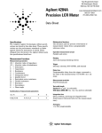
Change 1
Change the figure 10-5 of DC Bias Level Accuracy Test Setup without the Interface Box (page 10-9) as
follows.
C Copyright 2007 Agilent Technologies
○
マニュアル チェンジ
変更 1
DC バイアス・レベル確度試験接続(インタフェース・ボックス未使用)の図 10-5(ページ 10-9)を以下に
変更して下さい。
C Copyright 2007 Agilent Technologies
○
Agilent 4284A Precision LCR Meter Maintenance Manual
Manual Change
Agilent Part No. N/A
Apr 2012
Change 1
Change the test limits of 100pF standard for 510mV, 20 Hz on “D” value on page 10-14.
Change the test limits of 100pF standard for 510mV, 48 kHz on “D” value on page 10-14.
Table 10-7. Impedance Measurement Accuracy Test Limits (1 of 2)
Setting
Test Limits (Cp, D)
Signal
Level
Test
Frequency
510 mV
20 Hz
125 Hz
1 kHz
12.5 kHz
48 kHz
96 kHz
1 MHz
20 mV
5.1 V*
10pF standard
100 pF standard
1000 pF standard
Cp
C.V. ± 32.09 pF
D
± 0.03190
Cp
C.V. ± 1.759 pF
C.V. ± 3.05 pF
D
± 0.01739
± 0.00286
Cp
C.V. ± 0.312 pF
C.V. ± 1.00 pF
D
± 0.00293
± 0.00081
Cp
C.V. ± 0.0318 pF
C.V. ± 0.137 pF
C.V. ± 1.13 pF
D
± 0.0031
± 0.00130
± 0.00095
Cp
C.V. ± 0.0246 pF
C.V. ± 0.162 pF
C.V. ± 1.16 pF
D
± 0.0028
± 0.00190
± 0.00103
Cp
C.V. ± 0.0275 pF
C.V. ± 0.122 pF
C.V. ± 1.31 pF
D
± 0.0035
± 0.00116
± 0.00111
Cp
C.V. ± 0.0249 pF
C.V. ± 0.102 pF
C.V.1 ± 1.53 pF
D
± 0.0038
± 0.00082
± 0.00083
C.V. ± 0.898 pF
C.V. ± 2.53 pF
C.V. ± 0.208 pF
C.V.1 ± 2.59 pF
C.V. ± 0.293 pF
C.V. ± 1.48 pF
C.V. ± 0.152 pF
C.V.1 ± 2.03 pF
1kHz
Cp
1 MHz
Cp
1 kHz
Cp
1 MHz
Cp
C.V. ± 0.0402 pF
C.V. ± 0.0297 pF
C.V.: Standard’s calibration value at 1 kHz.
C.V.1: C.V. multiplied by 1.0003
* Option 001 only
C Copyright 2012 Agilent Technologies
○
Change 2
Change the value of 100pF standard for OSC Level 510 mV, 125 Hz on “MINIMUM” “Cp” value on page
10-42.
Change the minimum and maximum value of 100pF standard for OSC Level: 510mV, 48 kHz on “D” value
on page 10-42.
100pF Standard C.V.:
(Cal. Value at 1 kHz)
OSC Level: 510 mV
SIGNAL
FREQUENCY
125 Hz
MINIMUM
Cp
C.V. – 1.759 pF
– 0.01739
D
1 kHz
Cp
C.V. – 0.312 pF
– 0.00293
D
12.5 kHz
48 kHz
96 kHz
1 MHz
]
]
C.V. + 1.759 pF
0.01739
C.V. + 0.312 pF
0.00293
C.V. – 0.137 pF
C.V. + 0.137 pF
D
– 0.00130
0.00130
Cp
C.V. – 0.162 pF
C.V. + 0.162 pF
D
– 0.00190
0.00190
Cp
C.V. – 0.122 pF
C.V. + 0.122 pF
D
– 0.00116
0.00116
Cp
C.V. – 0.102 pF
C.V. + 0.102 pF
D
– 0.00082
0.00082
FAIL [
]
OSC Level: 5.1 V (Option 001 only)
PASS [
MAXIMUM
Cp
OSC Level: 20 mV
PASS [
ACTUAL
FAIL [
C Copyright 2012 Agilent Technologies
○
]
Agilent 4284A Precision LCR Meter Maintenance Manual
Manual Change
Agilent Part No. N/A
Sep 2012
Change 1
On Page 9-24, two lines from the bottom of the page, change Table A to read Table 9-7 as follows:
Where, P is the coefficient listed on Table 9-7.
Change 2
On Page 9-25, eight lines from the bottom of the page, change Table A to read Table 9-1 as follows:
P = 15 (according to Table 9-1).
Change 3
On Page 10-17 and 10-19, the first line below Table 10-9 and Table 10-10, change DC to read 1kHz as
follows:
C.V.,: Standard’s calibration value at 1 kHz.
Change 4
On Page F-1, change the numbers for the equation term “m” as follows:
m = 60000, 62500 or 75000.
C Copyright 2012 Agilent Technologies
○
CAUTIONS ON OPERATION
1. UNKNOWN (MEASUREMENT) TERMINALS
Do NOT apply DC voltage or current to the UNKNOWN terminals. Doing so will damage
the 4284A. Before you measure a capacitor, be sure the capacitor is fully discharged.
2. MEMORY CARD
Use Agilent Technologies-specified memory cards containing 4284A-specific data only. If
other memory cards are used, the 4284A may be damaged. Non 4284A-specific data
contained on a memory card is not guaranteed, and data may be lost.
To insert a memory card into the MEMORY card slot, hold the memory card with the label
facing upward and with the contacts at the slot opening・ Insert the card into the slot until
it "clicks" in place.
To remove a memory card from the 4284A, press the UNLOCK button and remove the
card.
Do NOT remove a memory card while LOADing or STORing data. Doing so may damage
the memory card and any data stored in the memory card may be lost.
Store memory cards in their furnished card cases when not in use. The card case protects
memory cards from contamination and electrostatic discharge.
Also, store memory cards under the following environmental conditions.
Storage Temperature Range: -30 oC to +70 oC
Storage Humidity Range: 30% to 85% (@ +50 oC)
Do NOT shock or stress memory cards.
When storing or moving your 4284A, be sure the memory card slot is empty (no memory
card inserted).
Do NOT touch the connector contact surface of a memory card and do NOT use chemical
liquids to clean the contacts.
3. HANDLER INTERFACE BOARD (0PTION 201)
If the +5V internal voltage (pin 16, 17 or 18 of the handler interface connector) is not
output,
output a fuse on the handler interface board (A32F1) has blown and must be replaced.
Two replacement fuses are furnished with the 4284A option 201. Additional fuses are
available from Agilent Technologies. Order PN 2110-0046.
Fuse:
Mpm Time Delay 0.5A 12.5V
If you need this fuse, contact your nearest Agilent Technologies Sales and Service Office.
To replace A32F1 , perform the following procedure.
1.
To remove the handler interface board (A32), perform procedure I through 7 on page
10-26.
10-26
2.
Remove A32F1 (indicated in Figure A) from socket and carefully insert the new fuse.
3.
Replace the handler interface board, top shield plate, rear feet, and top cover.
If the handler interface continues not to output +5V after A32F1 has been replaced,
contact the nearest Agilent Technologies office.
Safety Summary
When you notice any of the unusual conditions listed below, immediately
terminate operation and disconnect the power cable.
Contact your local Agilent Technologies sales representative or
authorized service company for repair of the instrument. If you continue
to operate without repairing the instrument, there is a potential fire or
shock hazard for the operator.
n Instrument operates abnormally.
n Instrument emits abnormal noise, smell, smoke or a spark-like light
during the operation.
n Instrument generates high temperature or electrical shock during
operation.
n Power cable, plug, or receptacle on instrument is damaged.
n Foreign substance or liquid has fallen into the instrument.
Safety notice supplement
・ This equipment complies with EN/IEC61010-1:2001.
・ This equipment is MEASUREMENT CATEGORY I (CAT I). Do not use for CAT II, III, or IV.
・ Do not connect the measuring terminals to mains.
・ This equipment is POLLUTION DEGREE 2, INDOOR USE product.
・ This equipment is tested with stand-alone condition or with the combination with the accessories supplied
by Agilent Technologies against the requirement of the standards described in the Declaration of
Conformity. If it is used as a system component, compliance of related regulations and safety requirements
are to be confirmed by the builder of the system.
Agilent 4284A PRECISION LCR METER
OPERATION MANUAL
(Including Option 001, 002, 006, 201, 202, 301)
SERIAL NUMBERS
This manual applies directly to instruments with the serial number
prex of 2940J02283,02285 and above, and whose ROM-based
rmware is version 01.20. For additional important information about
serial numbers, read \Serial Number" in Chapter 9 of this Operation
Manual.
Agilent Part No. 04284-90040
Printed in JAPAN
Eighth Edition
January 2001
Notice
The information contained in this document is subject to change
without notice.
This document contains proprietary information which is protected
by copyright. All rights are reserved. No part of this document
may be photocopied, reproduced, or translated to another language
without the prior written consent of the Agilent Technologies.
Agilent Technologies Japan, Ltd.
Component Test PGU-Kobe
1-3-2, Murotani, Nishi-ku, Kobe-shi,
Hyogo, 651-2241 Japan
c Copyright 1988, 1991, 1994, 1996, 1998, 2000, 2001
Agilent Technologies Japan, Ltd.
Manual Printing
History
The manual printing date and part number indicate its current
edition. The printing date changes when a new edition is printed.
(Minor corrections and updates which are incorporated at reprint do
not cause the date to change.) The manual part number changes
when extensive technical changes are incorporated.
December 1988 : : : : : : : : : : : : : : : : : : : : : : : : : : : : : : : : : : : : : : First Edition
April 1991 : : : : : : : : : : : : : : : : : : : : : : : : : : : : : : : : : : : : : : : : Second Edition
December 1991 : : : : : : : : : : : : : : : : : : : : : : : : : : : : : : : : : : : : : Third Edition
March 1994 : : : : : : : : : : : : : : : : : : : : : : : : : : : : : : : : : : : : : : : Fourth Edition
December 1996 : : : : : : : : : : : : : : : : : : : : : : : : : : : : : : : : : : : : : : Fifth Edition
August 1998 : : : : : : : : : : : Sixth Edition (part number: 04284-90040)
January 2000 : : : : : : : : Seventh Edition (part number: 04284-90040)
January 2001 : : : : : : : : : Eighth Edition (part number: 04284-90040)
iii
Safety Summary
The following general safety precautions must be observed during all
phases of operation, service, and repair of this instrument. Failure
to comply with these precautions or with specic WARNINGS
elsewhere in this manual may impair the protection provided by
the equipment. In addition it violates safety standards of design,
manufacture, and intended use of the instrument.
The Agilent Technologies assumes no liability for the customer's
failure to comply with these requirements.
Note
4284A complies with INSTALLATION CATEGORY II and
POLLUTION DEGREE 2 in IEC1010-1.4284A is INDOOR USE
product.
Note
LEDs in this product are Class 1 in accordance with IEC825-1.
CLASS 1 LED PRODUCT
Ground The Instrument
To avoid electric shock hazard, the instrument chassis and cabinet
must be connected to a safety earth ground by the supplied power
cable with earth blade.
DO NOT Operate In An
Explosive Atmosphere
Do not operate the instrument in the presence of ammable gasses or
fumes. Operation of any electrical instrument in such an environment
constitutes a denite safety hazard.
Keep Away From Live
Circuits
Operating personnel must not remove instrument covers. Component
replacement and internal adjustments must be made by qualied
maintenance personnel. Do not replace components with the power
cable connected. Under certain conditions, dangerous voltages may
exist even with the power cable removed. To avoid injuries, always
disconnect power and discharge circuits before touching them.
DO NOT Service Or
Adjust Alone
Do not attempt internal service or adjustment unless another person,
capable of rendering rst aid and resuscitation, is present.
DO NOT Substitute
Parts Or Modify
Instrument
Because of the danger of introducing additional hazards, do not
install substitute parts or perform unauthorized modications to the
instrument. Return the instrument to a Agilent Technologies Sales
and Service Oce for service and repair to ensure that safety features
are maintained.
iv
Dangerous Procedure
Warnings
Warning
Warnings , such as the example below, precede potentially dangerous
procedures throughout this manual. Instructions contained in the
warnings must be followed.
Dangerous voltages, capable of causing death, are present in this
instrument. Use extreme caution when handling, testing, and adjusting
this instrument.
Safety Symbols
General denitions of safety symbols used on equipment or in
manuals are listed below.
Instruction manual symbol: the product is marked
with this symbol when it is necessary for the user to
refer to the instruction manual.
Alternating current.
Direct current.
On (Supply).
O (Supply).
In position of push-button switch.
Out position of push-button switch.
Frame (or chassis) terminal. A connection to the
frame (chassis) of the equipment which normally
include all exposed metal structures.
This Warning sign denotes a hazard. It calls
attention to a procedure, practice, condition or the
like, which, if not correctly performed or adhered to,
could result in injury or death to personnel.
This Caution sign denotes a hazard. It calls
attention to a procedure, practice, condition or the
like, which, if not correctly performed or adhered to,
could result in damage to or destruction of part or all
of the product.
Note denotes important information. It calls
attention to a procedure, practice, condition or the
like, which is essential to highlight.
Axed to product containing static sensitive devices
use anti-static handling procedures to prevent
electrostatic discharge damage to component.
v
How To Use This
Manual
Chapter 1
Getting Started
Chapter 1 provides unpacking, initial inspection, and preparation
information necessary for you to know before you apply AC power.
Chapter 2
Overview
Chapter 2 provides information including a product overview and a
tour of the front panel, which will help you to quickly learn how to
operate the 4284A.
Chapter 3
DISPLAY FORMAT
Chapter 3 provides detailed information for the display format and
5 menu key.
measurement function, corresponding to 4
Chapter 4
MEAS SETUP
Chapter 5
CATALOG/SYSTEM
CONFIGURATION
DISPLAY FORMAT
Chapter 4 provides detailed information for the measurement
5 menu key.
condition setup, corresponding to 4
MEAS SETUP
Chapter 5 provides detailed information for the internal/external
memory and system conguration catalog of the 4284A,
corresponding to 4
5 menu key.
CATALOG/SYSTEM
Chapter 6
Measurement Basics
Chapter 6 provides the basic measurement procedure with the
general impedance theory and measurement techniques, and practical
measurement examples.
Chapter 7
Remote Control
Chapter 7 provides information to control the 4284A using the GPIB
interface.
Chapter 8
Command Reference
Chapter 8 provides detailed information for each of the 4284A GPIB
commands.
Chapter 9
General Information
Chapter 10
Performance Test
vi
This manual, the Operation Manual for the 4284A Precision LCR
Meter, contains ten chapters plus appendixes, organized for the
convenience of the rst time user. After you receive your 4284A,
begin with Chapter 1.
Chapter 9 provides the specications, rack mount/handle kit
installation, and other general information on the 4284A.
Chapter 10 provides the performance tests for the 4284A used
for incoming inspection and verication that your instrument is
completely calibrated.
Appendix A
Manual Changes
Appendix A contains Manual Changes and provides information for
using this manual with an 4284A manufactured before the printing
date of the manual.
Appendix B
Error and Warning
Messages
Appendix B lists the 4284A's error and warning messages with brief
descriptions and solutions and the system messages.
Appendix C
Initial Settings and
System Memory
Appendix C lists the 4284A's initial settings and functions whose
status is stored in internal system memory.
Appendix D
Correction Data
Appendix D provides information about the relationship between the
test frequency and the correction data.
Appendix E
Write Protection
Appendix E provides the procedure for write protecting all of the
stored data in the 4284A's memory card and internal EEPROM
memory.
Appendix F
Test Frequency Points
Appendix G
Transient States
Caused by
Measurement Condition
Changes
Typeface
Conventions
Appendix F lists all available test frequency points from 1 kHz to 1
MHz.
Appendix G describes the measurement condition changes which
cause the transient states, and lists the delay times required for
various transient states.
Bold
Italics
Computer
4HARDKEYS5
Boldface type is used when a term is dened.
For example: icons are symbols.
Italic type is used for emphasis and for titles
of manuals and other publications.
Italic type is also used for keyboard entries
when a name or a variable must be typed in
place of the words in italics. For example:
copy lename means to type the word copy,
to type a space, and then to type the name of
a le such as file1.
Computer font is used for on-screen prompts
and messages.
Labeled keys on the instrument front panel
are enclosed in 4 5.
vii
NNNNNNNNNNNNNNNNNNNNNNNNNN
SOFTKEYS
Certification
Warranty
viii
Softkeys located to the right of the Liquid
Crystal Display (LCD) are enclosed in .
NNNNN
Agilent Technologies certies that this product met its published
specications at the time of shipment from the factory. Agilent
Technologies further certies that its calibration measurements
are traceable to the United States National Institute of Standards
and Technology (nist), to the extent allowed by the Institute's
calibration facility, or to the calibration facilities of other
International Standards Organization members.
This Agilent Technologies instrument product is warranted against
defects in material and workmanship for a period of one year from
the date of shipment, except that in the case of certain components
listed in \Components not Covered by Warranty" in Chapter 9 of
this manual, the warranty shall be for the specied period. During
the warranty period, Agilent Technologies will, at its option, either
repair or replace products which prove to be defective.
For warranty service or repair, this product must be returned
to a service facility designated by Agilent Technologies. Buyer
shall prepay shipping charges to Agilent Technologies and Agilent
Technologies shall pay shipping charges to return the product to
Buyer. However, Buyer shall pay all shipping charges, duties, and
taxes for products returned to Agilent Technologies from another
country.
Agilent Technologies warrants that its software and rmware
designated by Agilent Technologies for use with an instrument will
execute its programming instruction when property installed on that
instrument. Agilent Technologies does not warrant that the operation
of the instrument, or software, or rmware will be uninterrupted or
error free.
Limitation of
Warranty
The foregoing warranty shall not apply to defects resulting from
improper or inadequate maintenance by Buyer, Buyer-supplied
software or interfacing, unauthorized modication or misuse,
operation outside of the environmental specications for the product,
or improper site preparation or maintenance.
No other warranty is expressed or implied. Agilent Technologies
specically disclaims the implied warranties of merchantability and
tness for a particular purpose.
Exclusive Remedies
Assistance
The remedies provided herein are buyer's sole and exclusive remedies.
Agilent Technologies shall not be liable for any direct, indirect, special,
incidental, or consequential damages, whether based on contract, tort,
or any other legal theory.
Product maintenance agreements and other customer assistance
agreements are available for Agilent Technologies products.
For any assistance, contact your nearest Agilent Technologies Sales
and Service Oce. Addresses are provided at the back of this
manual.
ix
Contents
1. Installation and Set Up Guide
Incoming Inspection . . . . . . . . .
Power Requirements . . . . . . . . .
Power Cable . . . . . . . . . . . .
Line Voltage and Fuse Selection . . . .
Line Voltage Selection . . . . . . . .
Fuse Selection . . . . . . . . .
Operation Environment . . . . . . . .
Electromagnetic Compatibility . . . . .
Ventilation Requirements . . . . . . .
Instruction for Cleaning . . . . . . . .
Rack/Handle Installation . . . . . . .
Option 907 Handle Kit . . . . . . .
Installing the Handle . . . . . . .
Option 908 Rack Flange Kit . . . . .
Mounting the Rack . . . . . . . .
Option 909 Rack Flange & Handle Kit
Mounting the Handle and Rack . .
.
.
.
.
.
.
.
.
.
.
.
.
.
.
.
.
.
.
.
.
.
.
.
.
.
.
.
.
.
.
.
.
.
.
.
.
.
.
.
.
.
.
.
.
.
.
.
.
.
.
.
.
.
.
.
.
.
.
.
.
.
.
.
.
.
.
.
.
.
.
.
.
.
.
.
.
.
.
.
.
.
.
.
.
.
1-1
1-2
1-2
1-4
1-4
1-4
1-5
1-5
1-6
1-6
1-6
1-7
1-7
1-7
1-7
1-8
1-8
Introduction . . . . . . . . . . . . . . . . . .
Product Introduction . . . . . . . . . . . . . .
A Tour of the Front Panel . . . . . . . . . . .
(1) LINE On/O . . . . . . . . . . . . . .
(2) LCD . . . . . . . . . . . . . . . . . .
(3) SOFTKEYs . . . . . . . . . . . . . .
(4) MENU Keys . . . . . . . . . . . . . .
(5) CURSOR Keys . . . . . . . . . . . . .
(6) ENTRY Keys . . . . . . . . . . . . . .
(7) GPIB Status Indicators . . . . . . . . .
(8) 4 5 Key . . . . . . . . . . . . . . . .
5 Key . . . . . . . . . . . . . .
(9) 4
(10) MEMORY Card Slot and UNLOCK Button
(11) 4
5 Key . . . . . . . . . . . . .
(12) CONTRAST Control Knob . . . . . . .
(13) UNKNOWN Terminals . . . . . . .
(14) FRAME Terminal . . . . . . . . . . .
A Tour of the Rear Panel . . . . . . . . . . .
(1) GPIB Interface Connector . . . . . . . .
(2) Interface Connectors . . . . . . . . . . .
2-1
2-1
2-2
2-2
2-2
2-2
2-2
2-3
2-3
2-3
2-3
2-3
2-3
2-3
2-3
2-4
2-4
2-4
2-5
2-5
2. Overview
LCL
TRIGGER
DC BIAS
Contents-1
(3) INT DC BIAS MONITOR Connector . .
(4) EXT TRIGGER Connector . . . . . . .
(5) LINE Input Receptacle . . . . . . . .
(6)
LINE Fuse Holder . . . . . . .
(7) LINE VOLTAGE SELECTOR . . . .
Display . . . . . . . . . . . . . . . . . . .
Display Area Denition . . . . . . . . . . .
Display Page Area . . . . . . . . . . . .
System Menu Field . . . . . . . . . . . .
Comment Line Area . . . . . . . . . . .
Softkey Area . . . . . . . . . . . . . . .
Measurement Data/Conditions Area . . . .
Input Line Area . . . . . . . . . . . . .
System Message Area . . . . . . . . . . .
MENU keys and Display Page . . . . . . . .
DISPLAY FORMAT MENU key . . . . . .
MEAS SETUP MENU key . . . . . . . .
CATALOG/SYSTEM menu key . . . . . .
Summary of Pages . . . . . . . . . . . . .
5)
.
MEAS DISPLAY (under 4
5)
BIN No. DISPLAY (under 4
BIN COUNT DISPLAY (under 4
LIST SWEEP DISPLAY (under 4
MEAS SETUP (under 4
5) . . . .
CORRECTION (under 4
5) . . . .
5)
LIMIT TABLE SETUP (under 4
5) .
LIST SWEEP SETUP (under 4
5) . . . .
CATALOG (under 4
5)
SYSTEM CONFIG (under 4
5) . . .
SELF TEST (under 4
Basic Operation . . . . . . . . . . . . . . .
DISPLAY FORMAT
DISPLAY FORMAT
.
.
.
.
.
.
.
.
.
.
.
.
.
.
.
.
.
.
.
.
.
)
)
DISPLAY FORMAT5
DISPLAY FORMAT5
MEAS SETUP
MEAS SETUP
MEAS SETUP
MEAS SETUP
CATALOG/SYSTEM
CATALOG/SYSTEM
CATALOG/SYSTEM
3. DISPLAY FORMAT Menu
Introduction . . . . . . . . . . . . . . . .
MEAS DISPLAY Page . . . . . . . . . . .
Measurement Function . . . . . . . . . .
Description . . . . . . . . . . . . . .
Front Panel Operation for Setting the
Measurement Function . . . . . . . .
Measurement Range . . . . . . . . . . .
Description . . . . . . . . . . . . . .
Front Panel Operation for Setting the
Measurement Range . . . . . . . . .
Test Frequency . . . . . . . . . . . . . .
Description . . . . . . . . . . . . . .
Front Panel Operation for Setting the Test
Frequency . . . . . . . . . . . . .
Oscillator Level . . . . . . . . . . . . .
Description . . . . . . . . . . . . . .
Contents-2
.
.
.
.
.
.
.
.
.
.
.
.
.
.
.
.
.
.
.
.
.
.
.
.
.
.
.
.
.
.
.
.
.
.
2-5
2-5
2-5
2-5
2-5
2-6
2-6
2-6
2-6
2-6
2-7
2-7
2-7
2-7
2-8
2-8
2-8
2-9
2-10
2-10
2-10
2-10
2-10
2-10
2-10
2-11
2-11
2-11
2-11
2-11
2-15
3-1
3-1
3-4
3-4
3-5
3-6
3-6
3-9
3-10
3-10
3-11
3-12
3-12
Front Panel Operation for Setting the Oscillator
Level . . . . . . . . . . . . . . . . .
DC Bias . . . . . . . . . . . . . . . . . . .
Description . . . . . . . . . . . . . . . .
Front Panel Operation for Setting the DC Bias .
Integration Time . . . . . . . . . . . . . . .
Description . . . . . . . . . . . . . . . .
Front Panel Operation for Setting the Integration
Time . . . . . . . . . . . . . . . . .
System Menu . . . . . . . . . . . . . . . .
Load/Store Function . . . . . . . . . . . .
Fixed Decimal Point Function . . . . . . . .
Printer Function . . . . . . . . . . . . . .
Keylock Function . . . . . . . . . . . . . .
BIN No. DISPLAY Page . . . . . . . . . . . .
Comparator Function ON/OFF . . . . . . . .
Description . . . . . . . . . . . . . . . .
Front Panel Operation for Setting the Comparator
Function to ON or OFF . . . . . . . . .
System Menu . . . . . . . . . . . . . . . .
Load/Store Function . . . . . . . . . . . .
Printer Function . . . . . . . . . . . . . .
Keylock Function . . . . . . . . . . . . . .
BIN COUNT DISPLAY Page . . . . . . . . . .
System Menu . . . . . . . . . . . . . . . .
Counter Function . . . . . . . . . . . . . .
Load/Store Function . . . . . . . . . . . .
Printer Function . . . . . . . . . . . . . .
Keylock Function . . . . . . . . . . . . . .
LIST SWEEP DISPLAY Page . . . . . . . . . .
Sweep Mode . . . . . . . . . . . . . . . . .
Front Panel Operation for Setting the Sweep Mode
of the List Sweep Measurement . . . . . .
System Menu . . . . . . . . . . . . . . . .
Load/Store Function . . . . . . . . . . . .
Printer Function . . . . . . . . . . . . . .
Keylock Function . . . . . . . . . . . . . .
4. MEAS SETUP Menu
Introduction . . . . . . . . . . . . . . . . . .
MEAS SETUP page . . . . . . . . . . . . . .
Comment . . . . . . . . . . . . . . . . . .
Description . . . . . . . . . . . . . . . .
Front Panel Operation for Entering a Comment
Number . . . . . . . . . . . . . . . .
Trigger Mode . . . . . . . . . . . . . . . .
Description . . . . . . . . . . . . . . . .
Front Panel Operation for Setting the Trigger
Mode . . . . . . . . . . . . . . . . .
Automatic Level Control Function . . . . . . .
Description . . . . . . . . . . . . . . . .
3-13
3-14
3-14
3-16
3-17
3-17
3-17
3-18
3-18
3-20
3-20
3-23
3-23
3-25
3-25
3-25
3-25
3-25
3-26
3-27
3-28
3-30
3-30
3-30
3-31
3-32
3-32
3-34
3-35
3-35
3-35
3-36
3-37
4-1
4-1
4-4
4-4
4-4
4-4
4-4
4-5
4-6
4-6
Contents-3
Front Panel Operation for Setting the Automatic
Level Control Function . . . . . . . . . .
High Power Mode . . . . . . . . . . . . . .
Description (Refer to Appendix G.) . . . . . .
Front Panel Operation for Setting the High Power
Mode . . . . . . . . . . . . . . . . .
Bias Current Isolation Function . . . . . . . .
Description (Refer to Appendix G.) . . . . . .
Front Panel Operation for Setting the Bias Current
Isolation Function . . . . . . . . . . . .
Averaging Rate . . . . . . . . . . . . . . .
Description . . . . . . . . . . . . . . . .
Front Panel Operation for Setting the Averaging
Rate . . . . . . . . . . . . . . . . . .
Delay Time . . . . . . . . . . . . . . . . .
Description (Refer to Appendix G.) . . . . . .
Front Panel Operation for Setting the Delay Time
Level Monitor Function . . . . . . . . . . . .
Description . . . . . . . . . . . . . . . .
Front Panel Operation for Setting the Level
Monitor Function . . . . . . . . . . . .
Deviation Measurement Function . . . . . . . .
Description . . . . . . . . . . . . . . . .
Front Panel Operation for the Deviation
Measurement Function . . . . . . . . . .
System Menu . . . . . . . . . . . . . . . .
Load/Store Function . . . . . . . . . . . .
Clear Setup Function . . . . . . . . . . . .
Printer Function . . . . . . . . . . . . . .
SYSTEM RESET Function . . . . . . . . .
CORRECTION Page . . . . . . . . . . . . . .
OPEN Correction . . . . . . . . . . . . . .
Description . . . . . . . . . . . . . . . .
Front Panel Operation for the Open Correction
SHORT Correction . . . . . . . . . . . . . .
Description . . . . . . . . . . . . . . . .
Front Panel Operation for the Short Correction
LOAD Correction . . . . . . . . . . . . . .
Description . . . . . . . . . . . . . . . .
Front Panel Operation for the
OPEN/SHORT/LOAD Correction . . . . .
Measurement Function for the Standard . . . . .
Description . . . . . . . . . . . . . . . .
Front Panel Operation for Setting the Standard's
Measurement Function . . . . . . . . . .
Single/Multi Correction Mode Selection . . . . .
Description . . . . . . . . . . . . . . . .
Front Panel Operation for Setting the Correction
Mode to the Multi Correction Mode . . . .
Cable Length Selection . . . . . . . . . . . .
Description . . . . . . . . . . . . . . . .
Contents-4
4-9
4-9
4-9
4-9
4-10
4-10
4-10
4-11
4-11
4-11
4-11
4-11
4-11
4-12
4-12
4-12
4-12
4-12
4-13
4-14
4-14
4-15
4-16
4-16
4-18
4-21
4-21
4-22
4-23
4-23
4-24
4-24
4-24
4-25
4-28
4-28
4-29
4-31
4-31
4-31
4-32
4-32
Front Panel For Selecting the Cable Length . .
System Menu . . . . . . . . . . . . . . . .
Printer Function . . . . . . . . . . . . . .
LIMIT TABLE SETUP Page . . . . . . . . . .
Swap Parameter Function . . . . . . . . . . .
Description . . . . . . . . . . . . . . . .
Front Panel Operation for Swapping the Primary
Parameter for the Secondary Parameter . .
Limit Mode for Comparator . . . . . . . . . .
Description . . . . . . . . . . . . . . . .
Front Panel Operation for Setting the Limit Mode
for the Comparator . . . . . . . . . . .
Nominal Value for Tolerance Mode . . . . . . .
Description . . . . . . . . . . . . . . . .
Front Panel Operation for Setting the Nominal
Value . . . . . . . . . . . . . . . . .
Comparator Function ON/OFF . . . . . . . .
Description . . . . . . . . . . . . . . . .
Front Panel Operation for Setting the Comparator
Function to ON or OFF . . . . . . . . .
Auxliary Bin ON/OFF . . . . . . . . . . . .
Description . . . . . . . . . . . . . . . .
Front Panel Operation for Setting the AUX BIN to
ON or OFF . . . . . . . . . . . . . . .
Low/High Limits . . . . . . . . . . . . . . .
Description . . . . . . . . . . . . . . . .
Front Panel Operation for Setting the Low/High
Limits . . . . . . . . . . . . . . . . .
System Menu . . . . . . . . . . . . . . . .
Load/Store Function . . . . . . . . . . . .
Clear Table Function . . . . . . . . . . . .
Printer Function . . . . . . . . . . . . . .
LIST SWEEP SETUP Page . . . . . . . . . . .
Sweep Mode . . . . . . . . . . . . . . . . .
Description . . . . . . . . . . . . . . . .
Front Panel Operation for Setting the List Sweep
Measurement Mode . . . . . . . . . . .
List Sweep Parameter . . . . . . . . . . . . .
Description . . . . . . . . . . . . . . . .
Front Panel Operation for Setting the List Sweep
Parameter . . . . . . . . . . . . . . .
Sweep Points and Limit Mode . . . . . . . . .
Description . . . . . . . . . . . . . . . .
Front Panel Operation for Setting the Sweep
Points . . . . . . . . . . . . . . . . .
System Menu . . . . . . . . . . . . . . . .
Load/Store Function . . . . . . . . . . . .
Clear Table Function . . . . . . . . . . . .
Printer Function . . . . . . . . . . . . . .
4-32
4-32
4-33
4-33
4-36
4-36
4-37
4-37
4-37
4-38
4-39
4-39
4-39
4-40
4-40
4-40
4-41
4-41
4-42
4-43
4-43
4-44
4-45
4-46
4-46
4-47
4-48
4-50
4-50
4-51
4-51
4-51
4-51
4-52
4-52
4-53
4-54
4-54
4-54
4-55
Contents-5
5. Catalog/System Conguration
Introduction . . . . . . . . . . . . . . . . . .
CATALOG Page . . . . . . . . . . . . . . . .
System Menu . . . . . . . . . . . . . . . .
Media Specifying . . . . . . . . . . . . . .
Load/Store Function . . . . . . . . . . . .
Printer Function . . . . . . . . . . . . . .
Purge Function . . . . . . . . . . . . . . .
SYSTEM CONFIG Page . . . . . . . . . . . .
Beeper Function ON/OFF . . . . . . . . . . .
Description . . . . . . . . . . . . . . . .
How to Set the Beeper to ON or OFF . . . . .
GPIB Setting . . . . . . . . . . . . . . . .
Description . . . . . . . . . . . . . . . .
How to Set the GPIB Address . . . . . . . .
How to Set the Talk Only Mode . . . . . . .
Handler Interface Setting . . . . . . . . . . .
Description . . . . . . . . . . . . . . . .
How to Set the Handler Interface to ON or OFF
Scanner Interface Setting . . . . . . . . . . .
Description . . . . . . . . . . . . . . . .
How to Set the Scanner Interface to ON or OFF
System Menu . . . . . . . . . . . . . . . .
Printer Function . . . . . . . . . . . . . .
SELF TEST Page . . . . . . . . . . . . . . .
Memory Card R/W Test . . . . . . . . . . .
Description . . . . . . . . . . . . . . . .
How to Perform the Memory Card R/W Test .
LED Display Test . . . . . . . . . . . . . .
Description . . . . . . . . . . . . . . . .
How to Perform the LED Display Test . . . .
LCD Display Test . . . . . . . . . . . . . .
Description . . . . . . . . . . . . . . . .
How to Perform the LCD Display Test . . . .
Handler I/F Test . . . . . . . . . . . . . . .
Description . . . . . . . . . . . . . . . .
Scanner I/F EEPROM R/W Test . . . . . . .
Description . . . . . . . . . . . . . . . .
How to Perform the Scanner I/F EEPROM R/W
Test . . . . . . . . . . . . . . . . . .
Scanner I/F I/O Test . . . . . . . . . . . . .
Description . . . . . . . . . . . . . . . .
Bias Current I/F I/O Test . . . . . . . . . . .
Description . . . . . . . . . . . . . . . .
Contents-6
5-1
5-1
5-3
5-3
5-3
5-4
5-4
5-5
5-7
5-7
5-7
5-8
5-8
5-8
5-8
5-8
5-8
5-9
5-9
5-9
5-9
5-10
5-10
5-11
5-13
5-13
5-13
5-14
5-14
5-14
5-14
5-14
5-14
5-14
5-14
5-15
5-15
5-15
5-16
5-16
5-16
5-16
6. Measurement Procedure and Examples
Introduction . . . . . . . . . . . . . . . . . .
Basic Measurement Procedure . . . . . . . . . .
Impedance Parameters . . . . . . . . . . . . .
Parallel/Series Circuit Mode . . . . . . . . . . .
Selecting Circuit Mode of Capacitance . . . . .
Small Capacitance (modeled by (a) in Figure 6-3)
Large Capacitance (modeled by (b) in Figure 6-3)
Selecting Circuit Mode of Inductance . . . . . .
Large Inductance (modeled by (a) in Figure 6-4)
Small Inductance (modeled by (b) in Figure 6-4)
Signal Level . . . . . . . . . . . . . . . . . .
Signal Level Across The DUT . . . . . . . . .
Oscillator Level Setting . . . . . . . . . . . .
Signal Level Setting Selection Example for
Inductance Measurements . . . . . . . .
Four-Terminal Pair Conguration . . . . . . . .
Measurement Contacts . . . . . . . . . . . . .
Capacitance To Ground . . . . . . . . . . . .
Contact Resistance . . . . . . . . . . . . . .
Extending Test Leads . . . . . . . . . . . . .
Guarding For Low Capacitance Measurements . .
Shielding . . . . . . . . . . . . . . . . . .
Correction Functions . . . . . . . . . . . . . .
Performing OPEN Correction . . . . . . . . .
Performing SHORT Correction . . . . . . . . .
Performing LOAD Correction . . . . . . . . .
Preparing the Standard . . . . . . . . . . .
Reference Values of the LOAD Standard . . .
Using the Pre-Measured Device for the LOAD .
Parasitics Incident to DUT Connection . . . . . .
Characteristics Example . . . . . . . . . . . . .
Capacitor Measurements . . . . . . . . . . . .
Inductance Measurements . . . . . . . . . . . .
If the 4284A does NOT Measure Correctly . . . . .
7. Remote Control
Introduction . . . . . . . . . . . .
General Purpose Interface Bus (GPIB)
GPIB Connection . . . . . . . .
GPIB Capability . . . . . . . . .
GPIB Addressing . . . . . . . . .
GPIB Bus Capability . . . . . . .
ABORT I/O (IFC) . . . . . . .
CLEAR LOCKOUT/SET LOCAL
DEVICE CLEAR (SDC or DCL) .
LOCAL (GTL) . . . . . . . . .
LOCAL LOCKOUT (LLO) . . .
REMOTE . . . . . . . . . . .
SPOLL . . . . . . . . . . . .
SERVICE REQUEST . . . . . .
.
.
.
.
.
.
.
.
.
.
.
.
.
.
.
.
.
.
.
.
.
.
.
.
.
.
.
.
.
.
.
.
.
.
.
.
.
.
.
.
.
.
.
.
.
.
.
.
.
.
.
.
.
.
.
.
.
.
.
.
.
.
.
.
.
.
.
.
.
.
.
.
.
.
.
.
.
.
.
.
.
.
.
.
6-1
6-1
6-2
6-5
6-5
6-5
6-5
6-6
6-6
6-6
6-7
6-7
6-8
6-8
6-9
6-10
6-11
6-12
6-13
6-15
6-15
6-16
6-19
6-19
6-20
6-20
6-20
6-21
6-22
6-23
6-24
6-28
6-32
7-1
7-1
7-1
7-3
7-4
7-4
7-4
7-4
7-4
7-4
7-5
7-5
7-5
7-5
Contents-7
TRIGGER (GET) . . . . . . . . . . . . .
Standard Commands for Programmable
Instruments(SCPI) . . . . . . . . . . . . .
Data Transfer . . . . . . . . . . . . . . . . .
ASCII Format . . . . . . . . . . . . . . . .
Binary Format . . . . . . . . . . . . . . . .
Floating Point Format . . . . . . . . . . . .
Trigger System . . . . . . . . . . . . . . . .
Data Buer Memory . . . . . . . . . . . . .
Status Byte . . . . . . . . . . . . . . . . . .
Enabling the Status Byte . . . . . . . . . . .
Operation Status Register Group . . . . . . . .
Standard Operation Status Condition Register .
Standard Operation Status Event Register . . .
Standard Operation Status Event Enable Register
Standard Event Status Register . . . . . . . .
Enabling the Event Status Register . . . . . . .
Sample Programs . . . . . . . . . . . . . . . .
Control Settings . . . . . . . . . . . . . . .
MEAS SETUP page . . . . . . . . . . . .
CORRECTION page . . . . . . . . . . . .
LIMIT TABLE SETUP page . . . . . . . .
LIST SWEEP SETUP page . . . . . . . . .
Data Transfer Examples . . . . . . . . . . . .
ASCII Format . . . . . . . . . . . . . . .
BINARY Format . . . . . . . . . . . . . .
8. Command Reference
Introduction . . . . . . . . . . .
Notation Conventions and Denitions
Command Structure . . . . . . .
Command Abbreviations . . . . .
Header and Parameters . . . . . .
NR1 . . . . . . . . . . . . .
NR2 . . . . . . . . . . . . .
NR3 . . . . . . . . . . . . .
Terminators . . . . . . . . . . .
Program Message Terminators . .
Response Message Terminators . .
Command Reference . . . . . . .
DISPlay Subsystem . . . . . . . .
:PAGE . . . . . . . . . . . . .
:LINE . . . . . . . . . . . . . .
FREQuency Subsystem . . . . . .
VOLTage Subsystem . . . . . . .
CURRent Subsystem . . . . . . .
AMPLitude Subsystem . . . . . .
OUTPut Subsystem . . . . . . .
:High POWer . . . . . . . . . .
:DC:ISOLation . . . . . . . . . .
BIAS Subsystem . . . . . . . . .
Contents-8
.
.
.
.
.
.
.
.
.
.
.
.
.
.
.
.
.
.
.
.
.
.
.
.
.
.
.
.
.
.
.
.
.
.
.
.
.
.
.
.
.
.
.
.
.
.
.
.
.
.
.
.
.
.
.
.
.
.
.
.
.
.
.
.
.
.
.
.
.
.
.
.
.
.
.
.
.
.
.
.
.
.
.
.
.
.
.
.
.
.
.
.
.
.
.
.
.
.
.
.
.
.
.
.
.
.
.
.
.
.
.
.
.
.
.
.
.
.
.
.
.
.
.
.
.
.
.
.
.
.
.
.
.
.
.
.
.
.
.
.
.
.
.
.
.
.
.
.
.
.
.
.
.
.
.
.
.
.
.
.
.
7-5
7-6
7-7
7-7
7-9
7-10
7-12
7-16
7-20
7-22
7-23
7-24
7-25
7-26
7-27
7-30
7-31
7-31
7-32
7-33
7-34
7-35
7-36
7-36
7-38
8-1
8-1
8-2
8-4
8-5
8-6
8-6
8-6
8-8
8-8
8-8
8-9
8-10
8-11
8-12
8-13
8-14
8-15
8-16
8-17
8-17
8-18
8-19
:STATe . . . . . . . . .
:VOLTage . . . . . . . .
:CURRent . . . . . . . .
FUNCtion Subsystem . . .
:IMPedance[:TYPE] . . .
:IMPedance:RANGe . . .
:IMPedance:RANGe :AUTO
:Source MONitor:VAC . .
:Source MONitor:IAC . . .
:DEV<n>:MODE . . . .
:DEV<n>:REFerence . . .
:DEV<n> :REFerence:FILL
LIST Subsystem . . . . .
:FREQuency . . . . . . .
:VOLTage . . . . . . . .
:CURRent . . . . . . . .
:BIAS:VOLTage . . . . .
:BIAS:CURRent . . . . .
:MODE . . . . . . . . .
:BAND<n> . . . . . . .
APERture Subsystem . . .
TRIGger Subsystem . . .
:IMMediate . . . . . . .
:SOURce . . . . . . . .
:DELay . . . . . . . . .
INITiate Subsystem . . .
[:IMMediate] . . . . . . .
:CONTinuous . . . . . .
FETCh? Subsystem . . .
[:IMP]? . . . . . . . . .
:Source MONitor:VAC? . .
:Source MONitor:IAC? . .
ABORt Subsystem . . . .
FORMat Subsystem . . .
MEMory Subsystem . . .
:DIM . . . . . . . . . .
:FILL . . . . . . . . . .
:CLEar . . . . . . . . .
:READ? . . . . . . . . .
CORRection Subsystem . .
:LENGth . . . . . . . .
:METHod . . . . . . . .
:OPEN . . . . . . . . .
:OPEN:STATe . . . . . .
:SHORt . . . . . . . . .
:SHORt:STATe . . . . . .
:LOAD:STATe . . . . . .
:LOAD:TYPE . . . . . .
:SPOT<n>:STATe . . . .
:SPOT<n>:FREQuency .
:SPOT<n>:OPEN . . . .
.
.
.
.
.
.
.
.
.
.
.
.
.
.
.
.
.
.
.
.
.
.
.
.
.
.
.
.
.
.
.
.
.
.
.
.
.
.
.
.
.
.
.
.
.
.
.
.
.
.
.
.
.
.
.
.
.
.
.
.
.
.
.
.
.
.
.
.
.
.
.
.
.
.
.
.
.
.
.
.
.
.
.
.
.
.
.
.
.
.
.
.
.
.
.
.
.
.
.
.
.
.
.
.
.
.
.
.
.
.
.
.
.
.
.
.
.
.
.
.
.
.
.
.
.
.
.
.
.
.
.
.
.
.
.
.
.
.
.
.
.
.
.
.
.
.
.
.
.
.
.
.
.
.
.
.
.
.
.
.
.
.
.
.
.
.
.
.
.
.
.
.
.
.
.
.
.
.
.
.
.
.
.
.
.
.
.
.
.
.
.
.
.
.
.
.
.
.
.
.
.
.
.
.
.
.
.
.
.
.
.
.
.
.
.
.
.
.
.
.
.
.
.
.
.
.
.
.
.
.
.
.
.
.
.
.
.
.
.
.
.
.
.
.
.
.
.
.
.
.
.
.
.
.
.
.
.
.
.
.
.
.
.
.
.
.
.
.
.
.
.
.
.
.
.
.
.
.
.
.
.
.
.
.
.
.
.
.
.
.
.
.
.
.
.
.
.
.
.
.
.
.
.
.
.
.
.
.
.
.
.
.
.
.
.
.
.
.
.
.
.
.
.
.
.
.
.
.
.
.
.
.
.
.
.
.
.
.
.
.
.
.
.
.
.
.
.
.
.
.
.
.
.
.
.
.
.
.
.
.
.
.
.
.
.
.
.
.
.
.
.
.
.
.
.
.
.
.
.
.
.
.
.
.
.
.
.
.
.
.
.
.
.
.
.
.
.
.
.
.
.
.
.
.
.
.
.
.
.
.
.
.
.
.
.
.
.
.
.
.
.
.
.
.
.
.
.
.
.
.
.
.
.
.
.
.
.
.
.
.
.
.
.
.
.
.
.
.
.
.
.
.
.
.
.
.
.
.
.
.
.
.
.
.
.
.
.
.
.
.
.
.
.
.
.
.
.
.
.
.
.
.
.
.
.
.
.
.
.
.
.
.
.
.
.
.
.
.
.
.
.
.
.
.
.
.
.
.
.
.
.
.
.
.
.
.
.
.
.
.
.
.
.
.
.
.
.
.
.
.
.
.
.
.
.
.
.
.
.
.
.
.
.
.
.
.
.
.
.
.
.
.
.
.
.
.
.
.
.
.
.
8-20
8-21
8-22
8-23
8-24
8-25
8-26
8-27
8-28
8-29
8-30
8-30
8-31
8-32
8-33
8-34
8-35
8-36
8-37
8-38
8-39
8-40
8-40
8-41
8-42
8-43
8-43
8-44
8-45
8-45
8-46
8-46
8-47
8-48
8-49
8-49
8-49
8-50
8-50
8-51
8-52
8-53
8-53
8-54
8-54
8-55
8-56
8-57
8-58
8-59
8-60
Contents-9
:SPOT<n>:SHORt . . . . .
:SPOT<n>:LOAD . . . . .
:SPOT<n>:LOAD :STANdard
:USE . . . . . . . . . . .
:USE:DATA? . . . . . . .
COMParator Subsystem . . .
[:STATe] . . . . . . . . .
:MODE . . . . . . . . . .
:TOLerance:NOMinal . . . .
:TOLerance:BIN<n> . . . .
:SEQuence:BIN . . . . . .
:Secondary LIMit . . . . . .
:Auxiliary BIN . . . . . . .
:SWAP . . . . . . . . . .
:BIN:CLEar . . . . . . . .
:BIN:COUNt[:STATe] . . . .
:BIN:COUNt:DATA? . . . .
:BIN:COUNt:CLEar . . . .
Mass MEMory Subsystem . .
:LOAD:STATe . . . . . . .
:STORe:STATe . . . . . . .
SYSTem:ERRor? . . . . . .
STATus Subsystem . . . . .
:OPERation[:EVENt]? . . .
:OPERation:CONDition? . .
:OPERation:ENABle . . . .
Common Commands . . . .
*CLS . . . . . . . . . . .
*ESE . . . . . . . . . . .
*ESR? . . . . . . . . . .
*SRE . . . . . . . . . . .
*STB? . . . . . . . . . .
*IDN? . . . . . . . . . .
*OPC . . . . . . . . . . .
*WAI . . . . . . . . . . .
*RST . . . . . . . . . . .
*TST? . . . . . . . . . .
*TRG . . . . . . . . . . .
*LRN? . . . . . . . . . .
*OPT? . . . . . . . . . .
.
.
.
.
.
.
.
.
.
.
.
.
.
.
.
.
.
.
.
.
.
.
.
.
.
.
.
.
.
.
.
.
.
.
.
.
.
.
.
.
.
.
.
.
.
.
.
.
.
.
.
.
.
.
.
.
.
.
.
.
.
.
.
.
.
.
.
.
.
.
.
.
.
.
.
.
.
.
.
.
.
.
.
.
.
.
.
.
.
.
.
.
.
.
.
.
.
.
.
.
.
.
.
.
.
.
.
.
.
.
.
.
.
.
.
.
.
.
.
.
.
.
.
.
.
.
.
.
.
.
.
.
.
.
.
.
.
.
.
.
.
.
.
.
.
.
.
.
.
.
.
.
.
.
.
.
.
.
.
.
.
.
.
.
.
.
.
.
.
.
.
.
.
.
.
.
.
.
.
.
.
.
.
.
.
.
.
.
.
.
.
.
.
.
.
.
.
.
.
.
.
.
.
.
.
.
.
.
.
.
.
.
.
.
.
.
.
.
.
.
.
.
.
.
.
.
.
.
.
.
.
.
.
.
.
.
.
.
.
.
.
.
.
.
.
.
.
.
.
.
.
.
.
.
.
.
.
.
.
.
.
.
.
.
.
.
.
.
.
.
.
.
.
.
.
.
.
.
.
.
.
.
.
.
.
.
.
.
.
.
.
.
.
.
.
.
.
.
.
.
.
.
.
.
.
.
.
.
.
.
.
.
.
.
.
.
.
.
.
.
.
.
.
.
.
.
.
.
.
.
.
.
.
.
.
.
.
.
.
.
.
.
.
.
.
.
.
.
.
.
.
.
.
.
.
.
.
.
.
.
8-60
8-61
8-62
8-63
8-64
8-65
8-66
8-67
8-68
8-69
8-70
8-71
8-72
8-73
8-73
8-74
8-75
8-75
8-76
8-76
8-76
8-77
8-78
8-79
8-80
8-81
8-82
8-82
8-83
8-84
8-85
8-86
8-87
8-88
8-88
8-89
8-89
8-90
8-91
8-92
Introduction . . . . . . . . . . . .
Components not Covered by Warranty
Serial Number . . . . . . . . . . .
Specications . . . . . . . . . . .
Measurement Functions . . . . . .
Measurement Parameters . . . .
Combinations . . . . . . . . .
Mathematical Functions . . . . .
Equivalent Measurement Circuit .
.
.
.
.
.
.
.
.
.
.
.
.
.
.
.
.
.
.
.
.
.
.
.
.
.
.
.
.
.
.
.
.
.
.
.
.
.
.
.
.
.
.
.
.
.
.
.
.
.
.
.
.
.
.
9-1
9-1
9-1
9-2
9-2
9-2
9-2
9-3
9-3
9. General Information
Contents-10
.
.
.
.
.
.
.
.
.
.
.
.
.
.
.
.
.
.
.
.
.
.
.
.
.
.
.
.
.
.
.
.
.
.
.
.
.
.
.
.
Ranging . . . . . . . . . . . . . .
Trigger . . . . . . . . . . . . . .
Delay Time . . . . . . . . . . . .
Measurement terminals . . . . . . .
Test Cable Length . . . . . . . . .
Standard . . . . . . . . . . . .
With Option 006 . . . . . . . . .
Integration Time . . . . . . . . . .
Averaging . . . . . . . . . . . . .
Test Signal . . . . . . . . . . . . .
Frequency . . . . . . . . . . . . .
Accuracy . . . . . . . . . . . .
Signal Modes . . . . . . . . . . .
Normal . . . . . . . . . . . . .
Constant . . . . . . . . . . . .
Signal Level . . . . . . . . . . . .
Output Impedance . . . . . . . . .
Test Signal Level Monitor . . . . . .
Display Range . . . . . . . . . . . .
Absolute Measurement Accuracy . . . .
jZj, jYj, L, C, R, X, G and B Accuracy
D accuracy . . . . . . . . . . . .
Q Accuracy . . . . . . . . . . . .
Accuracy . . . . . . . . . . . .
G Accuracy . . . . . . . . . . . .
Rp Accuracy . . . . . . . . . . . .
Rs Accuracy . . . . . . . . . . . .
Relative Measurement Accuracy . . . .
jZj, jYj, L, C, R, X, G and B Accuracy
D accuracy . . . . . . . . . . . .
Q Accuracy . . . . . . . . . . . .
Accuracy . . . . . . . . . . . .
G Accuracy . . . . . . . . . . . .
Rp Accuracy . . . . . . . . . . . .
Rs Accuracy . . . . . . . . . . . .
Example of C-D Accuracy Calculation .
Measurement Conditions . . . . . .
Specication Charts and Tables . . . .
4284A Calibration Accuracy . . . . . .
Correction Functions . . . . . . . . .
Zero Open . . . . . . . . . . . . .
Zero Short . . . . . . . . . . . . .
Load . . . . . . . . . . . . . . .
List Sweep . . . . . . . . . . . . . .
Comparator Function . . . . . . . . .
Sorting Modes . . . . . . . . . . .
Bin Count . . . . . . . . . . . . .
List Sweep Comparator . . . . . . .
DC Bias . . . . . . . . . . . . . . .
Setting Accuracy . . . . . . . . . .
Other Functions . . . . . . . . . . .
.
.
.
.
.
.
.
.
.
.
.
.
.
.
.
.
.
.
.
.
.
.
.
.
.
.
.
.
.
.
.
.
.
.
.
.
.
.
.
.
.
.
.
.
.
.
.
.
.
.
.
.
.
.
.
.
.
.
.
.
.
.
.
.
.
.
.
.
.
.
.
.
.
.
.
.
.
.
.
.
.
.
.
.
.
.
.
.
.
.
.
.
.
.
.
.
.
.
.
.
.
.
.
.
.
.
.
.
.
.
.
.
.
.
.
.
.
.
.
.
.
.
.
.
.
.
.
.
.
.
.
.
.
.
.
.
.
.
.
.
.
.
.
.
.
.
.
.
.
.
.
.
.
.
.
.
.
.
.
.
.
.
.
.
.
.
.
.
.
.
.
.
.
.
.
.
.
.
.
.
.
.
.
.
.
.
.
.
.
.
.
.
.
.
.
.
.
.
.
.
.
.
.
.
9-3
9-3
9-3
9-3
9-3
9-3
9-3
9-3
9-3
9-3
9-3
9-3
9-3
9-3
9-3
9-4
9-4
9-4
9-5
9-5
9-5
9-5
9-5
9-6
9-6
9-6
9-6
9-7
9-8
9-9
9-9
9-9
9-9
9-9
9-10
9-11
9-11
9-12
9-16
9-17
9-17
9-17
9-17
9-17
9-17
9-17
9-17
9-17
9-17
9-17
9-18
Contents-11
Store/Load . . . . . . . . . . . . . . . .
GPIB . . . . . . . . . . . . . . . . . . .
Interface Functions . . . . . . . . . . . .
Self Test . . . . . . . . . . . . . . . . .
Options . . . . . . . . . . . . . . . . . . .
Option 001 (Power Amp/DC Bias) . . . . . .
Test Signal Level . . . . . . . . . . . . . .
Output Impedance . . . . . . . . . . . . .
Test Signal Level Monitor . . . . . . . . . .
DC Bias Level . . . . . . . . . . . . . . .
Bias Current Isolation Function . . . . . . .
DC Bias Monitor Terminal . . . . . . . . .
Other Options . . . . . . . . . . . . . . . .
Furnished Accessories . . . . . . . . . . . . .
Power Requirements . . . . . . . . . . . . .
Line Voltage . . . . . . . . . . . . . . . .
Line Frequency . . . . . . . . . . . . . . .
Power Consumption . . . . . . . . . . . .
Operating Environment . . . . . . . . . . . .
Temperature . . . . . . . . . . . . . . . .
Humidity . . . . . . . . . . . . . . . . .
Altitude . . . . . . . . . . . . . . . . . .
Dimensions . . . . . . . . . . . . . . . . .
Weight . . . . . . . . . . . . . . . . . . .
Display . . . . . . . . . . . . . . . . . . .
Capable of Displaying . . . . . . . . . . . .
Number of Display Digits . . . . . . . . . .
Supplemental Performance Characteristics . . . . .
Stability . . . . . . . . . . . . . . . . . . .
Temperature Coecient . . . . . . . . . . . .
Settling Time . . . . . . . . . . . . . . . .
Frequency (fm) . . . . . . . . . . . . . . .
Test Signal Level . . . . . . . . . . . . . .
Measurement Range . . . . . . . . . . . .
Input Protection . . . . . . . . . . . . . . .
Measurement Time . . . . . . . . . . . . . .
Display Time . . . . . . . . . . . . . . .
GPIB Data Output Time . . . . . . . . . .
DC Bias (1.5 V/2 V) . . . . . . . . . . . . .
Option 001 (Power Amp/DC Bias) . . . . . . .
DC Bias Voltage . . . . . . . . . . . . . .
DC Bias Current . . . . . . . . . . . . . .
Relative Measurement Accuracy with Bias Current
Isolation . . . . . . . . . . . . . . . .
Calculation Example . . . . . . . . . . . . .
Measurement Conditions . . . . . . . . . .
DC Bias Settling Time . . . . . . . . . . . .
Rack/Handle Installation . . . . . . . . . . . .
Storage and Repacking . . . . . . . . . . . . .
Environment . . . . . . . . . . . . . . . . .
Original Packaging . . . . . . . . . . . . . .
Contents-12
9-18
9-18
9-18
9-18
9-18
9-18
9-18
9-18
9-19
9-19
9-20
9-20
9-20
9-20
9-20
9-20
9-20
9-20
9-21
9-21
9-21
9-21
9-21
9-21
9-21
9-21
9-21
9-21
9-21
9-22
9-22
9-22
9-22
9-22
9-22
9-23
9-23
9-23
9-24
9-24
9-24
9-24
9-24
9-25
9-25
9-26
9-27
9-28
9-28
9-28
Other Packaging . . . . . . . . . . . . . . .
10. Performance Tests
Introduction . . . . . . . . . . . . . . . . . .
Test Equipment . . . . . . . . . . . . . . . .
Performance Test Record . . . . . . . . . . . .
Calibration Cycle . . . . . . . . . . . . . . . .
System Reset . . . . . . . . . . . . . . . . .
Procedure . . . . . . . . . . . . . . . . . .
Test Frequency Accuracy Test . . . . . . . . . .
Equipment . . . . . . . . . . . . . . . . .
Procedure: . . . . . . . . . . . . . . . . . .
Test Signal Level/Level-Monitor Accuracy Test . . .
Equipment: . . . . . . . . . . . . . . . . .
Procedure: . . . . . . . . . . . . . . . . . .
DC Bias Level Accuracy Test . . . . . . . . . .
Equipment: . . . . . . . . . . . . . . . . .
Procedure: . . . . . . . . . . . . . . . . . .
Impedance Measurement Accuracy Test . . . . . .
Equipment: . . . . . . . . . . . . . . . . .
Procedure: . . . . . . . . . . . . . . . . . .
Store and Load Function Test . . . . . . . . . .
Equipment: . . . . . . . . . . . . . . . . .
Procedure: . . . . . . . . . . . . . . . . . .
GPIB Interface Test . . . . . . . . . . . . . .
Equipment: . . . . . . . . . . . . . . . . .
Procedure: . . . . . . . . . . . . . . . . . .
Bias Current Interface Function Test (Option 002 only)
Equipment: . . . . . . . . . . . . . . . . .
Procedure: . . . . . . . . . . . . . . . . . .
Handler Interface Function Test (Option 201 only) .
Equipment: . . . . . . . . . . . . . . . . .
Procedure: . . . . . . . . . . . . . . . . . .
Handler Interface Function Test (Option 202 only) .
Equipment: . . . . . . . . . . . . . . . . .
Procedure: . . . . . . . . . . . . . . . . . .
Scanner Interface Function Test (Option 301 only) .
Equipment: . . . . . . . . . . . . . . . . .
Procedure: . . . . . . . . . . . . . . . . . .
Supplying DC Power to the Simulator . . . . . . .
Procedure: . . . . . . . . . . . . . . . . . .
Performance Test Record . . . . . . . . . . . .
Test Signal Frequency Accuracy Test . . . . . .
Test Signal Level/Level-Monitor Accuracy Test . .
Multimeter Reading (Signal Frequency: 1.25 kHz,
Hi-PW: OFF) . . . . . . . . . . . . . .
Level Monitor Reading (Signal Frequency: 1.25
kHz, Hi-PW: OFF) . . . . . . . . . . .
Multimeter Reading (Signal Frequency: 960 kHz,
Hi PW: OFF) . . . . . . . . . . . . . .
9-28
10-1
10-1
10-2
10-2
10-4
10-4
10-5
10-5
10-5
10-6
10-6
10-7
10-9
10-9
10-10
10-12
10-12
10-12
10-20
10-20
10-20
10-21
10-21
10-21
10-23
10-23
10-23
10-26
10-26
10-26
10-30
10-30
10-30
10-33
10-33
10-33
10-36
10-36
10-37
10-37
10-37
10-37
10-37
10-38
Contents-13
Multimeter Reading (Signal Frequency: 1.25 kHz,
Hi PW: ON) Option 001 ONLY . . . . . .
Level Monitor Reading (Signal Frequency: 1.25
kHz, Hi-PW: ON) Option 001 ONLY . . .
Multimeter Reading (Signal Frequency: 960 kHz,
Hi PW: ON) Option 001 ONLY . . . . . .
Level Monitor Reading (Signal Frequency: 960
kHz, Hi-PW: ON) Option 001 ONLY . . .
DC Bias Voltage Accuracy Test . . . . . . . .
Hi-PW OFF . . . . . . . . . . . . . . . .
Hi-PW ON (Option 001 only) . . . . . . . .
Impedance Measurement Accuracy Test . . . . .
10 pF Standard . . . . . . . . . . . . . .
OSC Level: 510 mV . . . . . . . . . . . .
OSC Level: 20 mV . . . . . . . . . . . . .
OSC Level: 5.1 V (Option 001 only) . . . . .
100 pF Standard . . . . . . . . . . . . . . .
OSC Level: 510 mV . . . . . . . . . . . .
OSC Level: 20 mV . . . . . . . . . . . . .
OSC Level: 5.1 V (Option 001 only) . . . . .
1000 pF Standard . . . . . . . . . . . . . .
OSC Level: 510 mV . . . . . . . . . . . .
OSC Level: 20 mV . . . . . . . . . . . . .
OSC Level: 5.1 V (Option 001 only) . . . . .
0.01 F Standard . . . . . . . . . . . . . . .
OSC Level: 510 mV . . . . . . . . . . . .
OSC Level: 20 mV . . . . . . . . . . . . .
OSC Level: 5.1 V (Option 001 only) . . . . .
0.1 F Standard . . . . . . . . . . . . . . .
OSC Level :510 mV . . . . . . . . . . . . .
OSC Level: 20 mV . . . . . . . . . . . . .
OSC Level: 5.1 V (Option 001 only) . . . . .
1 F Standard . . . . . . . . . . . . . . . .
OSC Level :510 mV . . . . . . . . . . . . .
OSC Level: 20 mV . . . . . . . . . . . . .
OSC Level: 5.1 V (Option 001 only) . . . . .
100 Standard . . . . . . . . . . . . . . .
OSC Level :510 mV . . . . . . . . . . . . .
OSC Level: 20 mV . . . . . . . . . . . . .
OSC Level: 5.1 V (Option 001 only) . . . . .
1k Standard . . . . . . . . . . . . . . . .
OSC Level :510 mV . . . . . . . . . . . . .
OSC Level: 20 mV . . . . . . . . . . . . .
1 m Cable Length Operation . . . . . . . . . .
2 m Cable Length Operation (Option 006 only) .
4 m Cable Length Operation (Option 006 only) .
Store and Load Function Test . . . . . . . . .
GPIB Interface Test . . . . . . . . . . . . .
Bias Current Interface Function Test (Option 002
only) . . . . . . . . . . . . . . . . . .
Contents-14
10-38
10-38
10-39
10-39
10-40
10-40
10-40
10-41
10-41
10-41
10-41
10-42
10-42
10-42
10-42
10-42
10-43
10-43
10-43
10-43
10-44
10-44
10-44
10-44
10-44
10-44
10-44
10-44
10-45
10-45
10-45
10-45
10-45
10-45
10-45
10-45
10-46
10-46
10-46
10-46
10-46
10-46
10-46
10-46
10-46
A. Manual Changes
Introduction . .
Manual Changes
CHANGE1 . .
CHANGE2 . .
.
.
.
.
.
.
.
.
.
.
.
.
.
.
.
.
.
.
.
.
.
.
.
.
.
.
.
.
.
.
.
.
.
.
.
.
.
.
.
.
.
.
.
.
.
.
.
.
.
.
.
.
.
.
.
.
.
.
.
.
.
.
.
.
A-1
A-1
A-2
A-2
Introduction . . . . . . . . . . . .
Error Messages . . . . . . . . . . .
Operation Errors . . . . . . . . .
GPIB Errors . . . . . . . . . . .
Sample Program to Detect the Error
Operation Errors . . . . . . . . .
GPIB Errors . . . . . . . . . . .
System Message . . . . . . . . . .
Warning Messages . . . . . . . .
Instruction Messages . . . . . . .
.
.
.
.
.
.
.
.
.
.
.
.
.
.
.
.
.
.
.
.
.
.
.
.
.
.
.
.
.
.
.
.
.
.
.
.
.
.
.
.
.
.
.
.
.
.
.
.
.
.
.
.
.
.
.
.
.
.
.
.
B-1
B-1
B-1
B-1
B-2
B-3
B-9
B-11
B-11
B-12
Introduction . . . . . . . . . . . . . . . . . .
C-1
B. Error and Warning Messages
C. Initial Settings and System Memory
D. Correction Data
Introduction . . . . . . . . . . . . .
Test Frequency and Correction Frequency
Single Channel Correction Mode . . .
Multi Channel Correction Mode . . .
CORRECTION FUNCTION SETTING .
.
.
.
.
.
.
.
.
.
.
.
.
.
.
.
.
.
.
.
.
.
.
.
.
.
D-1
D-1
D-2
D-3
D-4
Introduction . . . . . . . . . . . . . . . . . .
Write Protection Procedure . . . . . . . . . . .
E-1
E-1
E. Write Protection
F. Test Frequency Point
Introduction . . . . . . . . . . . . . . . . . .
Frequency Points . . . . . . . . . . . . . . . .
F-1
F-1
G. Transient States Caused by Measurement Condition Changes
Introduction . . . . . . . . . . . . .
Changing the Test Frequency . . . . .
Changing the Measurement Range . . .
CHANGING THE DC BIAS VOLTAGE
Short Circuit Recovery . . . . . . . .
.
.
.
.
.
.
.
.
.
.
.
.
.
.
.
.
.
.
.
.
.
.
.
.
.
G-1
G-2
G-3
G-6
G-8
Index
Contents-15
Figures
1-1.
1-2.
1-3.
2-1.
2-2.
2-3.
2-4.
2-5.
2-6.
2-7.
3-1.
3-2.
3-3.
3-4.
3-5.
3-6.
3-7.
3-8.
3-9.
3-10.
3-11.
3-12.
3-13.
3-14.
3-15.
3-16.
3-17.
3-18.
4-1.
4-2.
4-3.
4-4.
4-5.
4-6.
4-7.
4-8.
Contents-16
Power Cable Supplied . . . . . . . . . . . . .
Line Voltage Selector . . . . . . . . . . . . .
Rack Mount Kits Installation . . . . . . . . .
Front Panel Overview . . . . . . . . . . . . .
Rear Panel Overview . . . . . . . . . . . . .
Display Area Denition . . . . . . . . . . . .
MENU keys . . . . . . . . . . . . . . . . .
Display Pages (1/3) . . . . . . . . . . . . . .
CURSOR Keys and Field Operation Example . .
Softkey Selection Example . . . . . . . . . . .
Available Fields on the MEAS DISPLAY Page . .
Available Softkeys on the MEAS DISPLAY Page .
Eective Measuring Range for Each Measurement
Range . . . . . . . . . . . . . . . . . .
Eective Measuring Range (Oscillator Level 2V or
20 mA) . . . . . . . . . . . . . . . .
Eective Measuring Range (Oscillator Level > 2V or
> 20 mA) . . . . . . . . . . . . . . . .
DC BIAS Current . . . . . . . . . . . . . .
DC BIAS Monitor Circuits . . . . . . . . . .
MEAS DISPLAY Page Example . . . . . . . .
Available Fields on the BIN No. DISPLAY Page .
Available Softkeys on the BIN No. DISPLAY Page
BIN No. DISPLAY Page Example . . . . . . .
Available Fields on the BIN COUNT DISPLAY Page
Available Softkeys on the BIN COUNT DISPLAY
Page . . . . . . . . . . . . . . . . . . .
BIN COUNT DISPLAY Page Example . . . . .
Available Fields on the LIST SWEEP DISPLAY
Page . . . . . . . . . . . . . . . . . . .
Available Softkeys on the LIST SWEEP DISPLAY
Page . . . . . . . . . . . . . . . . . . .
SEQ Mode and STEP Mode . . . . . . . . . .
LIST SWEEP DISPLAY Page Example . . . . .
Available Fields on the MEAS SETUP Page . . .
Available Softkeys on the MEAS SETUP Page . .
External Trigger Pulse . . . . . . . . . . . .
Feedback Circuit . . . . . . . . . . . . . . .
Available Operating Area for the ALC Function .
MEAS SETUP page After Clearing the Setup . .
MEAS SETUP page Example . . . . . . . . .
Available Fields on the CORRECTION Page . .
1-3
1-4
1-7
2-2
2-4
2-6
2-8
2-12
2-15
2-16
3-2
3-3
3-7
3-8
3-9
3-15
3-16
3-21
3-24
3-24
3-26
3-29
3-29
3-31
3-33
3-34
3-34
3-36
4-2
4-3
4-5
4-7
4-8
4-15
4-16
4-19
4-9. Available Softkeys on the CORRECTION Page .
4-10. Stray Admittance . . . . . . . . . . . . . .
4-11. OPEN/SHORT Correction Using The Interpolation
Method . . . . . . . . . . . . . . . . .
4-12. Residual Impedance . . . . . . . . . . . . .
4-13. OPEN/SHORT/LOAD Correction . . . . . . .
4-14. CORRECTION Page Example . . . . . . . . .
4-15. Available Fields on the LIMIT TABLE SETUP Page
4-16. Available Softkeys on the LIMIT TABLE SETUP
Page . . . . . . . . . . . . . . . . . . .
4-17. Swap Parameter Function . . . . . . . . . . .
4-18. Tolerance Mode and Sequential Mode . . . . . .
4-19. Limit Table Using the Sequential Mode . . . . .
4-20. LIMIT TABLE SETUP Page Example . . . . .
4-21. Available Fields on the LIST SWEEP SETUP Page
4-22. Available Softkeys on the LIST SWEEP SETUP
Page . . . . . . . . . . . . . . . . . . .
4-23. SEQ mode and STEP mode . . . . . . . . . .
4-24. List Sweep Settings . . . . . . . . . . . . . .
4-25. LIST SWEEP SETUP Page Example . . . . . .
5-1. Available Fields on the CATALOG Page . . . .
5-2. Available Softkeys on the CATALOG Page . . .
5-3. CATALOG Page Example . . . . . . . . . . .
5-4. Available Fields on the SYSTEM CONFIG Page .
5-5. Available Softkeys on the SYSTEM CONFIG Page
5-6. SYSTEM CONFIG page Example . . . . . . .
5-7. Available Fields on the SELF TEST Page . . . .
5-8. Available Softkeys on the SELF TEST Page . . .
6-1. Denition of Impedance . . . . . . . . . . . .
6-2. Vector Representation of Admittance . . . . . .
6-3. Capacitance Circuit Mode Selection . . . . . . .
6-4. Inductance Circuit Mode Selection . . . . . . .
6-5. Simplied Model of Signal Level and DUT . . . .
6-6. Four-Terminal Pair Measurement Principle . . .
6-7. Measurement Contacts . . . . . . . . . . . .
6-8. Model of Capacitance to Ground . . . . . . . .
6-9. Reducing Capacitance to Ground . . . . . . . .
6-10. Contact Resistance . . . . . . . . . . . . . .
6-11. Extending The Four-Terminal Pair Test Leads . .
6-12. Measurement Contacts for Test Leads Extension .
6-13. Example DUT Guard Plate Connection . . . . .
6-14. Guard Shield . . . . . . . . . . . . . . . .
6-15. Sample Shorting Plate . . . . . . . . . . . .
6-16. Shorting Plate Connection . . . . . . . . . . .
6-17. Parasitic Impedance Model (Using the 16047A/C/D)
6-18. Typical Characteristics of Components . . . . .
6-19. Connecting the 16047A . . . . . . . . . . . .
6-20. Connecting A Shorting Bar . . . . . . . . . .
6-21. Connecting DUT . . . . . . . . . . . . . . .
6-22. Measurement Results of A 470 pF Capacitor . . .
6-23. Connecting the 16047A . . . . . . . . . . . .
4-20
4-21
4-22
4-23
4-25
4-33
4-35
4-36
4-37
4-38
4-45
4-47
4-49
4-50
4-51
4-52
4-55
5-2
5-2
5-4
5-6
5-7
5-10
5-12
5-12
6-3
6-4
6-6
6-7
6-8
6-9
6-10
6-11
6-12
6-13
6-13
6-14
6-15
6-15
6-19
6-20
6-22
6-23
6-25
6-26
6-27
6-27
6-29
Contents-17
6-24.
6-25.
6-26.
7-1.
7-2.
7-3.
7-4.
7-5.
7-6.
7-7.
7-8.
7-9.
7-10.
7-11.
7-12.
7-13.
7-14.
7-15.
7-16.
7-17.
7-18.
7-19.
7-20.
7-21.
7-22.
7-23.
7-24.
7-25.
7-26.
7-27.
7-28.
7-29.
8-1.
8-2.
8-3.
8-4.
8-5.
8-6.
8-7.
8-8.
8-9.
8-10.
8-11.
8-12.
8-13.
Contents-18
Connecting A Shorting Bar . . . . . . . . . .
Connecting DUT . . . . . . . . . . . . . . .
Measurement Results of The Magnetic-Cored
Inductor . . . . . . . . . . . . . . . . .
GPIB Connector Signal/Pin Conguration . . . .
Typical GPIB System Interconnection . . . . . .
Functional Layers Diagram . . . . . . . . . .
ASCII Format 1 . . . . . . . . . . . . . . .
ASCII Format 2 (List Sweep) . . . . . . . . .
BINARY Format 1 . . . . . . . . . . . . . .
Binary Data Format For List Sweep Measurement
Trigger State Diagram . . . . . . . . . . . .
INITiate Subsystem Commands and Trigger System
Trigger System and Trigger Commands . . . . .
TRIGger:IMMediate Command Sample Program .
*TRG or GET Command Sample Program . . .
Triggering System and Data Transfer . . . . . .
Buered Data Transfer Sample Program and
Description . . . . . . . . . . . . . . . .
ASCII Format (Buer Memory) . . . . . . . .
BINARY Format (Buer Memory) . . . . . . .
Status Byte Register . . . . . . . . . . . . .
Operation Status Register Structure . . . . . .
Standard Event Status Register . . . . . . . .
MEAS SETUP Page . . . . . . . . . . . . .
CORRECTION page . . . . . . . . . . . . .
LIMIT TABLE SETUP page . . . . . . . . .
LIST SWEEP SETUP . . . . . . . . . . . .
Sample Program (Comparator) Using ASCII Format
Sample Program (Buer Memory) Using ASCII
Format . . . . . . . . . . . . . . . . . .
Sample Program (List Sweep) Using ASCII Format
Sample Program (Comparator) Using BINARY
Format . . . . . . . . . . . . . . . . . .
Sample Program (Buer Memory) Using BINARY
Format . . . . . . . . . . . . . . . . . .
Sample Program (List Sweep) Using BINARY
Format . . . . . . . . . . . . . . . . . .
Command Tree Example . . . . . . . . . . .
Command Header and Parameters . . . . . . .
DISPlay Subsystem Command Tree . . . . . . .
OUTPut Subsystem Command Tree . . . . . .
BIAS Subsystem Command Tree . . . . . . . .
FUNCtion Subsystem Command Tree . . . . . .
LIST Subsystem Command Tree . . . . . . . .
TRIGger Subsystem Command Tree . . . . . .
INITiate Subsystem Command Tree . . . . . .
FETCh? Subsystem Command Tree . . . . . .
MEMory Subsystem Command Tree . . . . . .
CORRection Subsystem Command Tree . . . . .
COMParator Subsystem Command Tree . . . .
6-30
6-31
6-31
7-2
7-3
7-6
7-7
7-9
7-10
7-11
7-12
7-12
7-13
7-14
7-14
7-15
7-16
7-18
7-18
7-20
7-23
7-28
7-32
7-33
7-34
7-35
7-36
7-37
7-37
7-38
7-39
7-39
8-2
8-5
8-10
8-17
8-19
8-23
8-31
8-40
8-43
8-45
8-49
8-51
8-65
8-14. Mass MEMory Subsystem Command Tree . . . .
8-15. STATus Subsystem Command Tree . . . . . . .
9-1. Serial Number Plate . . . . . . . . . . . . .
9-2. Test Signal Voltage and Test Frequency upper Limits
to apply measurement accuracy to 2 m and 4 m
Cable Length Operation. . . . . . . . . . .
9-3. Test Signal Voltage and DC Bias Voltage Upper
Limits Apply for Measurement Accuracy. . . .
9-4. Basic Accuracy A (1 of 2) . . . . . . . . . . .
9-5. Basic Accuracy A (2 of 2) . . . . . . . . . . .
9-6. Temperature Factor Ke . . . . . . . . . . . .
9-7. Maximum Capacitance Voltage . . . . . . . . .
9-8. Measurement Time . . . . . . . . . . . . . .
9-9. Rack Mount Kits Installation . . . . . . . . .
10-1. Test Frequency Accuracy Test Setup . . . . . .
10-2. Test Signal Level Accuracy Test Setup Using an
Interface Box . . . . . . . . . . . . . . .
10-3. Test Signal Level Accuracy Test Setup Without an
Interface Box . . . . . . . . . . . . . . .
10-4. DC Bias Level Accuracy Test Setup Using an
Interface Box . . . . . . . . . . . . . . .
10-5. DC Bias Level Accuracy Test Setup Without an
Interface Box . . . . . . . . . . . . . . .
10-6. Impedance Measurement Accuracy Test Setup . .
10-7. Correction Page Setup . . . . . . . . . . . .
10-8. GPIB Interface Test Setup . . . . . . . . . . .
10-9. Bias Interface Simulator . . . . . . . . . . . .
10-10. Bias Current Interface Function Test Setup . . .
10-11. Bias Current Interface Function Test . . . . . .
10-12. Interface Board Locations . . . . . . . . . . .
10-13. Jumper Settings . . . . . . . . . . . . . . .
10-14. Jumper Settings . . . . . . . . . . . . . . .
10-15. Handler Interface Function Test Set UP . . . . .
10-16. Handler Interface Function Check . . . . . . .
10-17. Jumper Settings . . . . . . . . . . . . . . .
10-18. Handler Interface Function Test Set up . . . . .
10-19. Handler Interface Function Check . . . . . . .
10-20. SW1 and SW2 settings . . . . . . . . . . . .
10-21. Scanner Simulator Connections . . . . . . . . .
10-22. A7 Board Location . . . . . . . . . . . . . .
E-1. A7 Digital Board Location . . . . . . . . . . .
E-2. Write Protection Switch . . . . . . . . . . . .
G-1. Required Delay Time After Changing the
Measurement Range (1) . . . . . . . . . .
G-2. Required Delay Time After Changing the
Measurement Range (2) . . . . . . . . . .
G-3. Required Delay Times After Changing the
Measurement Range (3) . . . . . . . . . .
G-4. Required Delay Times After Changing the DC Bias
(1) . . . . . . . . . . . . . . . . . . .
8-76
8-78
9-1
9-7
9-8
9-12
9-13
9-15
9-22
9-26
9-27
10-5
10-6
10-6
10-9
10-9
10-12
10-13
10-21
10-23
10-24
10-25
10-26
10-27
10-28
10-28
10-29
10-31
10-31
10-32
10-34
10-34
10-36
E-2
E-3
G-3
G-4
G-5
G-6
Contents-19
G-5.
G-6.
G-7.
G-8.
Contents-20
Required Delay Time After Changing the DC Bias
(2) . . . . . . . . . . . . . . . . . . .
Required Delay Times For Short Circuit Recovery (1)
Required Delay Times For Short Circuit Recovery (2)
Short Circuit Recovery Delay Times (3) . . . . .
G-7
G-8
G-9
G-10
Tables
1-1. 4284A Contents . . . . . . . . . . . . . . .
1-2. Line Voltage Selection . . . . . . . . . . . . .
1-3. Fuse Selection . . . . . . . . . . . . . . . .
1-4. Rack Mount Kits . . . . . . . . . . . . . . .
3-1. Measurement Function . . . . . . . . . . . .
3-2. Oscillator Level and Resolution (Std.) . . . . . .
3-3. Oscillator Level and Resolution (Opt.001) . . . .
3-4. DC bias and Resolution (Opt.001) . . . . . . .
3-5. DC Bias and Oscillator level Setting limits . . . .
4-1. Maximum DC Bias Current . . . . . . . . . .
6-1. Parallel/Series Circuit Mode . . . . . . . . . .
6-2. Correction Functions . . . . . . . . . . . . .
7-1. GPIB Interconnect Cables . . . . . . . . . . .
7-2. GPIB Interface Capability . . . . . . . . . . .
7-3. Data Format and Data Transfer Time . . . . . .
7-4. Status Byte Assignments . . . . . . . . . . .
7-5. Standard Operation Status Condition Register
Assignments . . . . . . . . . . . . . . .
7-6. Standard Operation Status Event Register
Assignments . . . . . . . . . . . . . . .
7-7. Standard Event Status Register Assignments . . .
8-1. Multiplier Mnemonics . . . . . . . . . . . . .
8-2. Sux Units and Available Commands . . . . . .
9-1. Impedance Proportional Factors Ka and Kb . . .
9-2. Cable Length Factor Kaa . . . . . . . . . . .
9-3. Cable Length Factor Kbb . . . . . . . . . . .
9-4. Calibration Interpolation Factor Kc . . . . . . .
9-5. Preset Calibration Frequencies . . . . . . . . .
9-6. Cable Length Factor Kd . . . . . . . . . . . .
9-7. Coecient Related to Test Frequency and
Measurement Range . . . . . . . . . . . .
9-8. Rack Mount Kits . . . . . . . . . . . . . . .
10-1. Recommended Test Equipment . . . . . . . . .
10-2. Test Frequency Test limits . . . . . . . . . . .
10-3. Test Signal Level/Level-Monitor Test Limits (Hi-PW
OFF) . . . . . . . . . . . . . . . . . .
10-4. Test Signal Level/Level-Monitor Test Limits (Hi-PW
ON) . . . . . . . . . . . . . . . . . . .
10-5. DC Bias Level Test Limits (Hi-PW OFF) . . . .
10-6. DC Bias Level Test Limits (Hi-PW ON) . . . . .
10-7. Impedance Measurement Accuracy Test Limits (1 of
2) . . . . . . . . . . . . . . . . . . . .
1-2
1-4
1-4
1-6
3-5
3-12
3-13
3-14
3-15
4-10
6-5
6-16
7-2
7-3
7-19
7-21
7-24
7-25
7-29
8-7
8-7
9-14
9-14
9-15
9-15
9-15
9-15
9-25
9-27
10-3
10-5
10-8
10-8
10-10
10-11
10-14
Contents-21
10-7. Impedance Measurement Accuracy Test Limits (2 of
2) . . . . . . . . . . . . . . . . . . . .
10-8. Impedance Measurement Accuracy Test Limits . .
10-9. Impedance Measurement Accuracy Test Limits for 1
m Cable Length Operation . . . . . . . . .
10-10. Impedance Measurement Accuracy Test Limits for 2
m and 4 m Cable Length Operation . . . . .
A-1. Manual Changes by Serial Number . . . . . . .
A-2. Manual Changes by Firmware's Version . . . . .
D-1. Correction Data Selecting Rule for SINGLE Mode
D-2. Correction Data Selecting Rule for MULTI Mode .
G-1. Measurement Condition Changes . . . . . . . .
Contents-22
10-15
10-16
10-17
10-19
A-1
A-1
D-2
D-3
G-1
1
Installation and Set Up Guide
This chapter provides the information necessary for performing an
incoming inspection and setting up the 4284A. The main topics in
this chapter are:
Incoming Inspection
Power requirements
Line Voltage and Fuse Selection
Operation Environment
Electromagnetic Compatibility
Ventilation Requirements
Instruction for Cleaning
Rack/Handle Installation
Incoming Inspection
Warning
To avoid hazardous electrical shock, do not turn on the 4284A when
there are signs of shipping damage to any portion of the outer
enclosure (for example, covers, panel, or display)
Inspect the shipping container for damage. If the shipping container
or cushioning material is damaged, it should be kept until the
contents of the shipment have been checked for completeness and the
4284A has been checked mechanically and electrically. The contents
of the shipment should be as listed in Table 1-1. If the contents
are incomplete, if there is mechanical damage or defect, or if the
analyzer does not pass the power-on selftests, notify the nearest
Agilent Technologies oce. If the shipping container is damaged,
or the cushioning material shows signs of unusual stress, notify the
carrier as well as the Agilent Technologies oce. Keep the shipping
materials for the carrier's inspection.
Installation and Set Up Guide
1-1
Table 1-1. 4284A Contents
4284A
Description
Power cable1
Operation Manual
1
1
|
04284-90020
Memory Card
1
04278-89001
Fuse
2
2110-0046
Handle kit
1
5061-9690
Rack Flange Kit
1
5061-9678
Rack Flange & Handle Kit
1
5061-9684
Option 004 Memory Card
Option 201 Fuse
Option 907 Handle Kit
Option 908 Rack Flange Kit
Option 909 Rack Flange & Handle Kit
1
Power Requirements
Power Cable
Warning
Qty. Agilent Part Number
Power Cable depends on where the instrument is used, see \Power Cable".
The 4284A requires the following power source:
Voltage : 90 to 132 Vac, 198 to 252 Vac
Frequency : 47 to 66 Hz
Power : 200 VA maximum
In accordance with international safety standards, this instrument
is equipped with a three-wire power cable. When connected to an
appropriate ac power outlet, this cable grounds the instrument
frame.
The type of power cable shipped with each instrument depends on
the country of destination. Refer to Figure 1-1 for the part numbers
of the power cables available.
For protection from electrical shock, the power cable ground must not
be defeated.
The power plug must be plugged into an outlet that provides a
protective earth ground connection.
1-2
Installation and Set Up Guide
1.Installation and
Set Up Guide
Figure 1-1. Power Cable Supplied
Installation and Set Up Guide 1-3
Line Voltage and
Fuse Selection
Figure 1-2 illustrates the line voltage selection switch and fuseholder
on the instrument's rear panel.
Figure 1-2. Line Voltage Selector
Caution
Line Voltage Selection
Before connecting the instrument to the power source, make sure
that the correct fuse has been installed and the Line Voltage
Selection Switch is correctly set.
Select the proper voltage selector according to the Table 1-2.
Table 1-2. Line Voltage Selection
Voltage
Selector
Line
Voltage
115 V 90{132 V, 47{66 Hz
230 V 198{252 V, 47{66 Hz
Fuse Selection
Select proper fuse according to the Table 1-3. Current ratings for
the fuse are printed under the fuseholder on the rear panel, and are
listed, along with the fuse's Agilent part number, in Table 1-3.
Table 1-3. Fuse Selection
Fuse
Fuse
Operating
Voltage Rating/Type Part Number
3A 250Vac
115 V UL/CSA type 2110-0381
Time Delay
2A 250Vac
230 V UL/CSA type 2110-0303
Time Delay
If you need this fuse,contact your nearest Agilent Technologies Sales
and Service Oce.
1-4
Installation and Set Up Guide
Caution
Operation
Environment
Note
Electromagnetic
Compatibility
To remove the fuse, turn the fuse holder counterclockwise until the
fuse pops out.
Use the proper fuse for the line voltage selected. Use only fuses with
the required current rating and of the specied type as replacements.
DO NOT use a mended fuse or short-circuit the fuse-holder in order
to by-pass a blown fuse. Find out what caused the fuse to blow!
The 4284A must be operated under within the following environment
conditions, and sucient space must be kept behind the 4284A to
avoid obstructing the air ow of the cooling fans.
Temperature: 0 C to 55 C
Humidity:
less than 95% RH at 40C
The 4284A must be protected from temperature extremes which
could cause condensation within the instrument.
This product has been designed and tested to the requirements of
the Electromagnetic Compatibility (EMC) Directive 89/336/EEC.
To use a properly shielded cable or shielded coaxial cable (such as
those recommended in the General Information and the Performance
Test) to connect each of the ports to their respective controllers,
peripherals, equipments or devices may ensure to meet the
requirements.
Installation and Set Up Guide
1-5
Ventilation
Requirements
Instruction for
Cleaning
Rack/Handle
Installation
To ensure adequate ventilation, make sure that there is adequate
clearance around the 4284A.
To prevent electrical shock, disconnect the 4284A power cable from
the receptacle before cleaning. Use a dry cloth or a cloth slightly
dipped in water to clean the casing. Do not attempt to clean the
4284A internally.
The analyzer can be rack mounted and used as a component in a
measurement system. Figure 1-3 shows how to rack mount the
4284A.
Table 1-4. Rack Mount Kits
Option
907
908
909
1-6
Installation and Set Up Guide
Description
Handle Kit
Rack Flange Kit
Rack Flange & Handle Kit
Agilent Part
Number
5061-9690
5061-9678
5061-9684
Figure 1-3. Rack Mount Kits Installation
Option 907 Handle Kit
Option 907 is a handle kit containing a pair of handles and the
necessary hardware to attach them to the instrument.
Installing the Handle
1. Remove the adhesive-backed trim strips 1 from the left and right
front sides of the 4284A. (Refer to Figure 1-3.)
2. Attach the front handles 2 to the sides using the screws provided.
3. Attach the trim strips 3 to the handles.
Option 908 Rack Flange
Kit
Option 908 is a rack ange kit containing a pair of anges and
the necessary hardware to mount them to the instrument in an
equipment rack with 482.6 mm (19 inches) horizontal spacing.
Mounting the Rack
1. Remove the adhesive-backed trim strips 1 from the left and right
front sides of the 4284A. (Refer to Figure 1-3.)
2. Attach the rack mount ange 4 to the left and right front sides of
the 4284A using the screws provided.
3. Remove all four feet 5 (lift bar on the inner side of the foot, and
slide the foot toward the bar.)
Installation and Set Up Guide
1-7
Option 909 Rack Flange
& Handle Kit
Option 909 is a rack mount kit containing a pair of anges and the
necessary hardware to mount them to an instrument which has
handles attached, in an equipment rack with 482.6 mm (19 inches)
spacing.
Mounting the Handle and Rack
1. Remove the adhesive-backed trim strips 1 from the left and right
front sides of the 4284A.
2. Attach the front handle 3 and the rack mount ange 5 together
on the left and right front sides of the 4284A using the screws
provided.
3. Remove all four feet (lift bar on the inner side of the foot, and
slide the foot toward the bar).
1-8
Installation and Set Up Guide
2
Overview
Introduction
Product Introduction
This Chapter provides the information you will need to know before
operating the Agilent 4284A Precision LCR Meter. Before using the
4284A, read through this Chapter so you can quickly and eciently
learn the 4284A's operation.
The 4284A is a general purpose LCR meter for incoming inspection
of components, quality control, and laboratory use. The 4284A is
used for evaluating LCR components, materials, and semiconductor
devices over a wide range of frequencies (20 Hz to 1 MHz) and test
signal levels (5 mV to 2 Vrms, 50 A to 20 mArms ). With Option 001
the 4284A's test signal level range spans 5 mV to 20 Vrms, and 50 A
to 100 mArms.
The 4284A oers C-D measurements with a basic accuracy of
6 0.05% (C), 6 0.0005 (D) at all test frequencies with six digit
resolution (the dissipation factor resolution is 0.000001) on every
range.
With its built-in comparator, the 4284A can output
comparison/decision results for sorting components into a maximum
of ten bins. By using the handler interface and scanner interface
options, the 4284A can easily be combined with a component
handler, a scanner, and a system controller to fully automate
component testing, sorting, and quality control data processing.
The 4284A's new list sweep function permits entry of up to ten
frequencies, test signal levels, or bias level points to be automatically
measured.
The GPIB interface is a standard interface on the 4284A and can be
used to build an automatic test system to completely characterize
new components and materials, and to fully automatic production
line testing.
The 4284A with Option 002 can apply a 0 to 20A (Maximum
40A : When two 42841As are paralleled.) DC current bias to the
DUT (Device Under Test). So, high current biased impedance
measurement of coils or transformers can be performed easy, fast and
safe.
Overview
2-1
A Tour of the Front
Panel
Figure 2-1 shows the brief description of each key on the 4284A's
front panel.
Figure 2-1. Front Panel Overview
(1) LINE On/Off
Power on/o switch. In the \ON" position all operating voltages
are applied to the instrument. In the \OFF" position NO operating
voltages are applied to the instrument.
(2) LCD
The Liquid Crystal Display (LCD) displays measurement results, test
conditions, etc.
(3) SOFTKEYs
Five softkeys are used to select control and parameter functions.
Each softkey has a softkey label along its left side.
(4) MENU Keys
Menu selection keys. There are three menu keys, 4
5,
4
5, and 4
5. The menu keys are used to
access the corresponding selection of instrument controls.
DISPLAY FORMAT
MEAS SETUP
2-2
Overview
CATALOG/SYSTEM
(5) CURSOR Keys
The CURSOR keys are used to move the eld select cursor from eld
to eld on the LCD display page. When the cursor is moved to a
eld, the eld changes to an inverse video image of the original eld.
The cursor can only be moved from eld to eld.
(6) ENTRY Keys
The ENTRY keys are used to enter numeric data into the 4284A.
The ENTRY keys are composed of the digits 4 5 to 4 5, a period 4 5,
5 terminates
5 keys. 4
a minus sign 4 5, 4 5, and 4
numeric input data and enters the displayed value on the Input
5
Line (second line from the bottom of the LCD screen). 4
deletes one last character of the input value.
0
ENTER
-
.
9
ENTER
BACK SPACE
BACK SPACE
(7) GPIB Status Indicators
The GPIB status indicators consist of the RMT (remote), TLK
(talk), LTN (listen), and SRQ (service request) indicators. These
indicators are used to show the 4284A's GPIB status when it is
interfaced to a controller via GPIB.
(8)
4LCL5
Key
This is the Local (LCL) key which sets the 4284A to local
(front-panel) control, if it was in REMOTE and if the GPIB
controller had not invoked a local lockout. 4 5 is the only
front-panel key that is active when the 4284A is in REMOTE state.
LCL
(9)
4TRIGGER5
Key
This is the TRIGGER key used to manually trigger the 4284A when
it is set to the Manual Trigger mode.
(10) MEMORY Card Slot and UNLOCK Button
The MEMORY card slot is where you insert the memory cards. The
UNLOCK button is used to eject a memory card.
(11)
4DC
BIAS5 Key
5 is a
5 used to enable the DC bias output. 4
This is 4
toggle type switch, and the DC BIAS ON/OFF LED indicator is
5 is set to ON, the DC BIAS
5. When 4
located above 4
5 is set to OFF, the
ON/OFF LED indicator is ON. When 4
DC BIAS ON/OFF LED indicator is OFF. If 4
5 is set to OFF,
even though the DC bias is set to ON according to the LCD display,
the DC bias isn't output.
DC BIAS
DC BIAS
DC BIAS
DC BIAS
DC BIAS
DC BIAS
(12) CONTRAST Control Knob
This knob is used to adjust the LCD's CONTRAST.
Overview
2-3
(13)
UNKNOWN Terminals
These are the UNKNOWN Terminals used to connect a four-terminal
pair test xture or test leads for measuring the device under
test.Available four terminal-pair test xtures or test leads are refer
to the Accessories Selection Guide For Impedance Measurements
(Catalog number 5963-6834E).
INSTALLATION CATEGORY I
Caution
Do not apply DC voltage or current to the UNKNOWN
terminals. Doing so will damage the 4284A. Before you measure a
capacitor, be sure the capacitor is fully discharged.
(14) FRAME Terminal
This is the FRAME Terminal which is tied to the instrument's
chassis and which can be used for measurements that require
guarding.
A Tour of the Rear
Panel
Figure 2-2 shows a brief description of the 4284A's rear panel.
Figure 2-2. Rear Panel Overview
2-4
Overview
(1) GPIB Interface Connector
This is the GPIB interface connector used when operating on the
General Purpose Interface Bus.
(2) Interface Connectors
When interface options are installed, the interface connectors will
be installed as shown. When the 4284A is not equipped with an
interface option, blank covers are installed.
(3) INT DC BIAS MONITOR Connector
This BNC connector is the internal DC BIAS monitor connector used
for monitoring the DC bias voltage applied to the device under test.
This connector is installed only when Option 001 is installed.
(4) EXT TRIGGER Connector
This BNC connector is the external trigger connector used to input
the positive-going TTL pulse signal to trigger the 4284A. (The
trigger mode must be set to EXTernal.)
(5)
LINE Input Receptacle
AC power cord receptacle.
(6)
LINE Fuse Holder
Fuse holder for the 4284A's line fuse. Refer to CHAPTER 1 to
determine the correct line fuse rating.
(7)
LINE VOLTAGE SELECTOR
The switch used to match the 4284A to the AC operating voltage
being used. Refer to CHAPTER 1 to determine the correct operating
voltage.
Overview
2-5
Display
Display Area Definition
The following paragraphs dene the display areas and elds, and
describes the LCD's display pages.
The 4284A uses a 40 character by 16 line Liquid Crystal Display
(lcd) , and the display area on the LCD is divided into the areas
shown in Figure 2-3.
Figure 2-3. Display Area Definition
Display Page Area
This is the display page area. This area identies the current display
page.
System Menu Field
The system menu area is always displayed on all pages (except for
the SELF TEST page) as the SYS MENU eld. When the cursor is
set on the SYS MENU eld, common system functions which are
not displayed on the display pages (for example, LOAD/STORE
function), or controls which cannot be set on a display page's elds,
are made available.
Comment Line Area
The comment line area is used to display comment messages sent
via the GPIB bus using the DISPlay:LINE command or entered on
the MEAS SETUP page using the 4 5 to 4 5, 4 5 (period), 4 5 (minus)
keys. Up to 30 characters can be displayed. The comment line area
is displayed on the following pages.
0
MEAS DISPLAY
BIN No. DISPLAY
LIST SWEEP DISPLAY
MEAS SETUP
2-6
Overview
9
.
-
LIST SWEEP SETUP
SYSTEM CONFIG
Softkey Area
The last six character positions of each line are reserved for softkey
labels. The softkeys displayed correspond to the eld at the cursor's
position on the LCD.
Measurement Data/Conditions Area
Note
This area is where measurement results and measurement conditions
are displayed.
Under certain conditions one of the following messages may be
displayed instead of the measurement results.
\UNBAL":
This message is displayed when the impedance of the
device exceeds the range of the analog measurement
circuit's capability.
\ADC ERR": This message is displayed when the A/D converter in
the measurement circuit is not functioning.
\------":
This message is displayed and is called \overow"
when the analog measurement circuit can measure
the device, but the data format used will not hold
the calculated results.
\INFINITY": This message is displayed when an attempt is made
to divide by zero during parameter calculation. For
example, if you set the 1 % measurement function
without setting the reference value, this message will
be displayed.
Input Line Area
This area is the input line where numeric input data entered with the
front panel keys is displayed.
System Message Area
This area is where system messages, comments, and error messages
are displayed.
Overview
2-7
MENU keys and Display
Page
The 4284A has three MENU keys which are used to dene the LCD
display pages.
Figure 2-4. MENU keys
Each MENU key has three or four display pages as follows.
DISPLAY FORMAT MENU key
This MENU key has the following four pages.
MEAS DISPLAY
BIN No. DISPLAY
BIN COUNT DISPLAY
LIST SWEEP DISPLAY
These display pages are used for displaying the measurement
results, and displaying the sorting results. Some controls for each
display page can be set from the display page. Only from the above
display pages can the 4284A measure a device under test. When
5 is pressed, the MEAS DISPLAY page will be
4
displayed on the LCD screen, and the softkeys used to select the
other three pages are displayed. The cursor will be positioned
at the MEAS DISPLAY eld. The power-on default display
page is the MEAS DISPLAY page. For more information under
5, refer to Chapter 3.
4
DISPLAY FORMAT
DISPLAY FORMAT
MEAS SETUP MENU key
This MENU key has the following four pages.
MEAS SETUP
CORRECTION
LIMIT TABLE SETUP
2-8
Overview
LIST SWEEP SETUP
These display pages are used for setting the measurement conditions
(including the correction function), or setting the bin sorting limits.
When one of these display pages are being displayed, the 4284A
cannot perform measurement, and also cannot perform bin sorting
judgments. (The 4284A can only measure a device under test
and can perform the bin judgments from the display pages under
5 is pressed, the MEAS SETUP
5.) When 4
4
page must be displayed, and the softkeys used to select the other
three pages are displayed. The cursor will be positioned at the
5, refer
MEAS SETUP eld. For more information about 4
to Chapter 3.
DISPLAY FORMAT
MEAS SETUP
MEAS SETUP
CATALOG/SYSTEM menu key
This MENU key has the following three pages.
CATALOG
SYSTEM CONFIGURATION
SELF TEST
These display pages are used for operating conditions other than
5 is pressed, the
main measurement control. When 4
CATALOG page will be displayed, and the softkeys used to select
the other two pages are displayed. The cursor will be positioned at
5,
the CATALOG eld. For more information about 4
refer to Chapter 5.
Starting from the next paragraph, a summary for each display page
will be given.
CATALOG/SYSTEM
CATALOG/SYSTEM
Overview
2-9
Summary of Pages
Figure 2-5 shows all display pages. Each summary of each page is
shown below.
MEAS DISPLAY (under
4DISPLAY
FORMAT5)
This display page provides the measurement result information, and
control settings are entered from this page. The 4284A measures
the device under test from this page, and displays the measurement
results in large characters.
BIN No. DISPLAY (under
4DISPLAY
FORMAT5)
This display page provides the bin sorting result information, the
measurement results, and comparator function on/o settings. The
4284A measures the device under test from this page. The bin
number is displayed in large characters, and the measurement results
are displayed in normal characters.
BIN COUNT DISPLAY (under
4DISPLAY
FORMAT5)
This display page provides the limit table's conditions, and the
comparator's bin counter results. The 4284A can measure the device
under test from this page, but the measurement results will not be
displayed.
LIST SWEEP DISPLAY (under
4DISPLAY
FORMAT5)
This display page provides the list sweep measurement results, and
the sweep mode step/seq selection. The 4284A measures the device
under test according to the list sweep conditions in the LIST SWEEP
SETUP page. An asterisk (*) shows the current measuring point in
the list sweep points. The list sweep point cannot be set from this
5)
page. You must use the LIST SWEEP SETUP (in 4
page to set the list sweep points.
MEAS SETUP
MEAS SETUP (under
4MEAS
SETUP5)
This display page provides all of the measurement control settings.
The 4284A cannot perform a measurement from this page, and the
measurement result can not be displayed on this page. When you
measure the device under test using the control settings on this page,
5.
use one of the display pages from 4
DISPLAY FORMAT
CORRECTION (under
4MEAS
SETUP5)
This display page provides the correction function. The correction
function must be used to measure the device under test accurately.
The 4284A cannot measure the device under test from this page, and
the measurement results will not be displayed. When you measure a
device under test, use one of the display pages from 4
5.
DISPLAY FORMAT
2-10
Overview
LIMIT TABLE SETUP (under
4MEAS
SETUP5)
4MEAS
SETUP5)
This display page provides the limit table settings for bin sorting.
The 4284A cannot perform a measurement from this page, and the
comparison results can not be displayed. When you want to see the
comparison results, either the BIN No. DISPLAY page (under
5) or the BIN COUNT DISPLAY page (under
4
5) must be used.
4
DISPLAY FORMAT
DISPLAY FORMAT
LIST SWEEP SETUP (under
This display page provides the control settings for the List Sweep
measurement function. The 4284A cannot measure the device under
test from this page, and the list sweep measurement results can not
be displayed from this page. When you measure the device under
test using the control settings on the LIST SWEEP SETUP page,
5) must be
the LIST SWEEP DISPLAY page (in 4
used.
DISPLAY FORMAT
CATALOG (under
4CATALOG/SYSTEM5)
This display page provides the catalog of the stored contents in
internal memory or a from the memory card.
SYSTEM CONFIG (under
4CATALOG/SYSTEM5)
This display page provides the operation of either the GPIB interface
or the 4284A's options, and will also tell you the option installation
information.
SELF TEST (under
4CATALOG/SYSTEM5)
This display page provides the 4284A's self test utilities and the the
Performance Test given in Chapter 10.
Overview
2-11
Figure 2-5. Display Pages (1/3)
2-12
Overview
Figure 2-5. Display Pages (2/3)
Overview
2-13
Figure 2-5. Display Pages (3/3)
2-14
Overview
Basic Operation
The 4284A's basic operation is described in the following paragraphs.
Display the desired display page using both the MENU keys and
the softkeys. (Refer to Figure 2-5.)
Move the cursor to the eld to be used using the CURSOR arrow
keys. The cursor will be an inverse video marker, and the eld is
the area to which you can set the cursor.
Figure 2-6. CURSOR Keys and Field Operation Example
The softkeys corresponding to the eld pointed to by the cursor
will be displayed. Select and press a softkey. The numeric entry
keys and 4 5 are used to enter numeric data.
When one of the numeric entry keys is pressed, the softkeys will
change to the available unit softkeys. You can use these unit
softkeys instead of 4 5. When 4 5 is used, the numeric
data is entered with Hz, V, or A as the default unit depending on
the cursor eld selected, e.g., test frequency's unit will be Hz, etc.
ENTER
ENTER
ENTER
Overview
2-15
Figure 2-7. Softkey Selection Example
2-16
Overview
3
DISPLAY FORMAT Menu
Introduction
This Chapter provides information about the function of each page of
5. The following four display pages can be called from
4
4
5.
DISPLAY FORMAT
DISPLAY FORMAT
MEAS DISPLAY
BIN No. DISPLAY
BIN COUNT DISPLAY
LIST SWEEP DISPLAY
This Chapter describes the functions on each page in the order of the
preceding list.
MEAS DISPLAY
Page
5, the MEAS DISPLAY page will be
When you press 4
displayed. On this MEAS DISPLAY page, the measurement results
are displayed in large characters, and the following measurement
controls can be set from this page. (The eld in parenthesis is used
to set the control function.)
Measurement Function (FUNC )
Measurement Range (RANGE )
Test Frequency (FREQ )
Oscillator Level (LEVEL)
DC Bias (BIAS )
Integration Time (INTEG )
System Menu (SYS MENU )
There are eight elds on this page: MEAS DISPLAY , FUNC ,
RANGE , FREQ , LEVEL, BIAS , INTEG , and SYS MENU . Each
control function is described in the following paragraphs.
This page also provides the following information in monitor areas
on the displayed page. These conditions can be set from the MEAS
SETUP page or CORRECTION page. (For more detail of the
following information, refer to Chapter 4.)
Oscillator Level Voltage/Current Monitor value (Vm, Im)
OPEN, SHORT, LOAD on/o setting conditions (CORR )
Channel Number (CH ) when the scanner interface is used.
The available elds and the softkeys which correspond to the elds
on this page are shown in Figure 3-1 and Figure 3-2 respectively.
DISPLAY FORMAT
DISPLAY FORMAT Menu
3-1
Figure 3-1. Available Fields on the MEAS DISPLAY Page
3-2
DISPLAY FORMAT Menu
Figure 3-2. Available Softkeys on the MEAS DISPLAY Page
DISPLAY FORMAT Menu
3-3
Measurement Function
Description
The 4284A measures two components of the complex impedance
(parameters) at the same time in a measurement cycle. The
measurement parameters are listed as follows.
Primary Parameters
jZj (absolute value of impedance)
jYj (absolute value of admittance)
L (inductance)
C (capacitance)
R (resistance)
G (conductance)
Secondary Parameters
D (dissipation factor)
Q (quality factor)
Rs (ESR (equivalent series resistance))
Rp (equivalent parallel resistance)
X (reactance)
B (susceptance)
(phase angle)
The primary parameter measurement result is located on the upper
line as two large character lines on this page, and the secondary
parameter measurement result is located on the lower line as two
large character lines on this page.
The combinations of primary and secondary parameters, including
the equivalent parallel and serial combinations, are listed in Table
3-1.
3-4
DISPLAY FORMAT Menu
Table 3-1. Measurement Function
Primary
Parameter
Z
Serial Mode
Z- (rad)
Z- (deg)
Y
C
C -D
C -Q
C -R
s
s
s
s
Parallel Mode
Y- (rad)
Y- (deg)
C -D
C -Q
C -G
C -R
L -D
L -Q
L -G
L -R
p
p
p
p
L
L -D
L -Q
L -R
s
s
s
s
p
p
p
p
R
G
R-X
p
p
G-B
Front Panel Operation for Setting the Measurement Function
Perform the following steps to set the measurement function.
1. Use the CURSOR arrow keys to move the cursor to the FUNC
eld. The following softkeys will be displayed.
NNNNNNNNNNNNNN
Cp-D
NNNNNNNNNNNNNN
Cp-Q
NNNNNNNNNNNNNN
Cp-G
NNNNNNNNNNNNNNNNN
Cp-Rp
NNNNNNNNNNNNNNNNNNNNNNNNNN
more 1/6
2. Select and press a softkey to set the measurement function. If the
softkey you want is not displayed, press more 1/6 to display the
following set of softkeys.
NNNNNNNNNNNNNNNNNNNNNNNNNN
NNNNNNNNNNNNNN
Cs-D
NNNNNNNNNNNNNN
Cs-Q
NNNNNNNNNNNNNNNNN
Cs-Rs
NNNNNNNNNNNNNNNNNNNNNNNNNN
more 2/6
3. Select and press a softkey to set the measurement function. If the
softkey you want is not displayed, press more 2/6 to display the
following set of softkeys.
NNNNNNNNNNNNNNNNNNNNNNNNNN
NNNNNNNNNNNNNN
Lp-D
NNNNNNNNNNNNNN
Lp-Q
DISPLAY FORMAT Menu
3-5
NNNNNNNNNNNNNN
Lp-G
NNNNNNNNNNNNNNNNN
Lp-Rp
NNNNNNNNNNNNNNNNNNNNNNNNNN
more 3/6
4. Select and press a softkey to set the measurement function. If the
softkey you want is not displayed, press more 3/6 to display the
following set of softkeys.
NNNNNNNNNNNNNNNNNNNNNNNNNN
NNNNNNNNNNNNNN
Ls-D
NNNNNNNNNNNNNN
Ls-Q
NNNNNNNNNNNNNNNNNNNN
Ls-Rs>
NNNNNNNNNNNNNNNNNNNNNNNNNN
more 4/6
5. Select and press a softkey to set the measurement function. If the
softkey you want is not displayed, press more 4/6 to display the
following set of softkeys.
NNNNNNNNNNNNNNNNNNNNNNNNNN
NNNNNNNNNNN
R-X
NNNNNNNNNNNNNNNNNNNNNNNNNNNNN
Z- (deg)
NNNNNNNNNNNNNNNNNNNNNNNNNNNNN
Z- (rad)
NNNNNNNNNNNNNNNNNNNNNNNNNN
more 5/6
6. Select and press a softkey to set the measurement function. If the
softkey you want is not displayed, press more 5/6 to display the
following set of softkeys.
NNNNNNNNNNNNNNNNNNNNNNNNNN
NNNNNNNNNNN
G-B
NNNNNNNNNNNNNNNNNNNNNNNNNNNNN
Y- (deg)
NNNNNNNNNNNNNNNNNNNNNNNNNNNNN
Y- (rad)
NNNNNNNNNNNNNNNNNNNNNNNNNN
more 6/6
7. Select and press a softkey to set the measurement function.
When more 6/6 is pressed, the softkeys shown in step 1 will be
displayed. Retry steps 1 through 7 if you missed the function you
were looking for.
NNNNNNNNNNNNNNNNNNNNNNNNNN
Measurement Range
Description
The 4284A has eight measurement ranges: 10
, 100
, 300
, 1 k
, 3
k
, 10 k
, 30 k
, and 100 k
. When Option 001 is installed, the
4284A has nine measurement ranges: 1
, 10
, 100
, 300
, 1 k
, 3
k
, 10 k
, 30 k
, and 100 k
. The measurement range is selected
according to the DUT's impedance even if measurement parameter is
capacitance or inductance.
Figure 3-3 shows the display range and eective measuring range for
each measurement range while in the impedance mode (jZj, R, X).
For example, 50 k
DUT impedance can be measured using from the
3-6
DISPLAY FORMAT Menu
100 to the 30 k
range, but the 4284A's measurement accuracy
specication is only met by using the 30 k
range. If this DUT is
measured by the 100 k
range, UNBAL will be displayed.
Figure 3-3. Effective Measuring Range for Each Measurement Range
Figure 3-4 and Figure 3-5 show the eective measuring range of each
measurement range, in which the 4284A's measurement accuracy
meets its specication. When the measurement range is set manually,
the optimum measurement range should be selected by matching
the DUT's impedance to the eective measuring range shown in
Figure 3-4 and Figure 3-5. When the measurement range is set to
AUTO, the optimum measurement range is automatically selected
according to the impedance of each DUT.
DISPLAY FORMAT Menu
3-7
Figure 3-4.
Effective Measuring Range
(Oscillator Level
3-8
DISPLAY FORMAT Menu
2V or
20 mA)
Figure 3-5.
Effective Measuring Range
(Oscillator Level
Note
>
2V or
>
20 mA)
The measurement range is limited by the test frequency setting
when the oscillator level is equal to 2 V or less than 2 V. When
the measurement range and the test frequency are set under the
above conditions, the test frequency must be set rst, and then the
measurement range. If you set the measurement range rst and then
frequency, the resulting measurement range may not be the one you
wanted to set.
Front Panel Operation for Setting the Measurement Range
Perform the following procedure to set the measurement range.
1. Move the cursor to the RANGE eld using the CURSOR keys.
The following softkeys will be displayed.
DISPLAY FORMAT Menu
3-9
This softkey is used to set the measurement range to
AUTO.
HOLD
This softkey is used to change the measurement range
from the AUTO mode to the HOLD mode. When
the measurement range is set to the HOLD mode, the
impedance range is xed at the current range setting,
and the impedance range is displayed in the RANGE
eld.
INCR * This softkey is used to increment the measurement
range in the HOLD (xed range) mode.
DECR + This softkey is used to decrement the measurement
range in the HOLD (xed range) mode.
2. Use the softkeys to set the measurement range.
NNNNNNNNNNNNNN
AUTO
NNNNNNNNNNNNNN
NNNNNNNNNNNNNNNNNNNN
NNNNNNNNNNNNNNNNNNNN
Test Frequency
Description
The 4284A operates from 20 Hz to 1 MHz with 8610 frequency steps
in between. All of test frequency points (F) are calculated values
using the following formula. (All available frequency points above 1
kHz are shown in Appendix F.)
m
F =
[kHz]
n
Where,
Frequency [F]
m
60, 62.5,
and 75
5 kHz < F 10 kHz (34 points) 120, 125,
and 150
10 kHz < F 20 kHz (34 points) 240, 250,
and 300
20 kHz < F 250 kHz (63 points) 480, 500
and 600
250 kHz < F 500 kHz (6 points) 960, 1000
and 1200
500 kHz < F 1 MHz (6 points) 1920, 2000
and 2400
20 Hz F 5 kHz (8467 points)
n
13 to 3750
(integer)
13 to 29
(integer)
13 to 29
(integer)
2 to 29
(integer)
2, 3, and 4
2, 3, and 4
When numeric data is entered, the nearest available frequency point
is automatically set.
3-10
DISPLAY FORMAT Menu
Front Panel Operation for Setting the Test Frequency
There are two ways to set the test frequency. One is to use the
softkeys, and the other is to use the numeric entry keys. Perform the
following steps to set the test frequency.
1. Move the CURSOR to the FREQ eld. The following softkeys
will be displayed.
*
NNNNNNNNNNNNNNNNNNNN
INCR
This softkey is the coarse frequency increment softkey used to
increment the test frequency to the next sequentially higher
tenfold value after 20 Hz. The frequency points set using this
softkey are as follows.
20 Hz 100 Hz
1 kHz 10 kHz 100 kHz 1 MHz
"
NNNNNNNNNNNNNNNNNNNN
INCR
This softkey is the ne frequency increment softkey used to
increment the current test frequency to the next sequentially
higher frequency point. There are 10 frequency points between
successive decade values. The sequential frequency points which
can be set using this softkey are as follows.
20 Hz
25 Hz
30 Hz
40 Hz
50 Hz
60 Hz
80 Hz
100 Hz 1 kHz 10 kHz 100 kHz 1 MHz
120 Hz 1.2 kHz 12 kHz 120 kHz
150 Hz 1.5 kHz 15 kHz 150 kHz
200 Hz 2 kHz 20 kHz 200 kHz
250 Hz 2.5 kHz 25 kHz 250 kHz
300 Hz 3 kHz 30 kHz 300 kHz
400 Hz 4 kHz 40 kHz 400 kHz
500 Hz 5 kHz 50 kHz 500 kHz
600 Hz 6 kHz 60 kHz 600 kHz
800 Hz 8 kHz 80 kHz 800 kHz
#
NNNNNNNNNNNNNNNNNNNN
DECR
This softkey is the ne frequency decrement softkey used to
decrease the test frequency to the next sequentially lower
frequency point. There are ten frequency points between
successive decade values. The frequency points set using this
softkey are the same values as set using INCR " .
NNNNNNNNNNNNNNNNNNNN
+
NNNNNNNNNNNNNNNNNNNN
DECR
This softkey is the coarse frequency decrement softkey which is
used to decrement the test frequency to the next sequentially
lower tenth value. The frequency points set using this softkey
are the same as the frequency points set using INCR * .
2. Select and set the test frequency using either the softkeys or the
numeric entry keys. When the test frequency is entered using the
numeric entry keys, the softkey labels are changed to the available
NNNNNNNNNNNNNNNNNNNN
DISPLAY FORMAT Menu
3-11
units ( Hz , kHz , and MHz ), and so you can use these softkeys
instead of 4 5 to enter the units and enter the data. When
4
5 is used, the numeric data is entered with Hz as the default
unit.
NNNNNNNN
NNNNNNNNNNN
NNNNNNNNNNN
ENTER
ENTER
Oscillator Level
Description
Note
The 4284A's oscillator level can be set as the eective value (RMS
value) of a sine wave of the test frequency from the 4284A's internal
oscillator. You can set either the oscillator voltage level or the
oscillator current level. The output impedance is 100
.
The set value of the oscillator current level is the value set when the
measurement contacts (UNKNOWN Terminals) are shorted together.
The set value of the oscillator voltage level is the value set when the
measurement contacts (UNKNOWN Terminals) are opened.
When the Option 001 (power amplier/DC-bias) isn't installed,
the oscillator voltage level can be set from 0 Vrms to 2 Vrms with a
resolution as listed in Table 3-2, or the oscillator current level can be
set from 0 Arms to 20 mArms with a resolution as listed in Table 3-2.
Table 3-2. Oscillator Level and Resolution (Std.)
Mode
Voltage
Oscillator Level
0V
5 mV to 200 mV
210 mV to 2 V
0A
50 A to 2 mA
2.1 mA to 20 mA
rms
rms
rms
Level
rms
3-12
DISPLAY FORMAT Menu
rms
rms
rms
rms
Note
Resolution
rms
rms
1 mV
10 mV
rms
rms
10 A
100 A
rms
rms
When the option 001 (power amplier/DC-bias) is installed, the
oscillator voltage level can be set form 0 Vrms to 20 Vrms with a
resolution as listed in Table 3-3, or the oscillator current level can be
set from 0 Arms to 200 mArms with a resolution as listed in Table 3-3.
It is possible to make the option 001 valid or invalid from the MEAS
SETUP page. When the option 001 function is used, the high power
mode must be set to ON in the MEAS SETUP page. (For more
information, refer to Chapter 4.)
Table 3-3. Oscillator Level and Resolution (Opt.001)
Mode
Oscillator Level
Voltage
Resolution
0V
5 mV to 200 mV
210 mV to 2 V
2.1 V to 20 V
0A
50 A to 2 mA
2.1 mA to 20 mA
21 mA to 200 mA
rms
rms
rms
rms
rms
Level
rms
rms
rms
rms
rms
rms
rms
rms
rms
1 mV
10 mV
100 mV
10 A
100 A
1 mA
rms
rms
rms
rms
rms
rms
The 4284A can measure a device using a constant voltage or current
level by using the automatic level control function. (The automatic
level control function (ALC eld) can be set to ON from the
MEAS SETUP page.) When a constant voltage or current level
measurement is performed, the asterisk mark (*) is located at the
head of the oscillator level value. For more information about the
automatic level control function, refer to Chapter 4.
Front Panel Operation for Setting the Oscillator Level
There are two ways to set the oscillator level. One is to use the
softkeys, and the other is to use the use the numeric entry keys.
Perform the following steps to set the oscillator level.
1. Move the cursor to the LEVEL eld. The following softkeys will
be displayed.
*
NNNNNNNNNNNNNNNNNNNN
INCR
Press this softkey to increases the oscillator's output level.
+
NNNNNNNNNNNNNNNNNNNN
DECR
Press this softkey to decreases the oscillator's output level.
2. Select and set the oscillator level using either the softkeys or the
numeric entry keys. When the oscillator level is entered using the
numeric entry keys, the softkey labels are changed to the available
units labels ( mV , V , A , mA , and A ), and you can use these
softkeys to enter the units and enter the data instead of 4 5.
When 4 5 is used, the numeric data is entered with V or A as
the default unit.
When you want to change the oscillator level from voltage to current,
or from current to voltage, the numeric entry keys and units' softkeys
must be used.
NNNNNNNN
NNNNN
NNNNNNNN
NNNNNNNN
NNNNN
ENTER
ENTER
Note
DISPLAY FORMAT Menu
3-13
DC Bias
Description
Note
The 4284A has internal dc bias voltage selections of 0 V, 1.5 V, and
2.0 V.
When option 001 is installed, the dc bias voltage can be set from 0
V to 6 40 V with a resolution as listed in Table 3-4, or the DC bias
current can be set from 0 A to 6 100 mA with a resolution as listed
in Table 3-4.
Option 001 can be made valid or invalid from the MEAS SETUP
page. When the option 001 function is used, the high power mode
must be set to ON from the MEAS SETUP page. (For more
information, refer to Chapter 4.)
Table 3-4. DC bias and Resolution (Opt.001)
Mode
DC Bias Level
Voltage 6 (0 V to 4 V)
6 (4.002 V to 8 V)
6 (8.005 V to 20 V)
6 (20.01 V to 40 V)
Current 6 (0 A to 40 mA)
6 (40.02 mA to 80 mA)
6 (80.05 mA to 100 mA)
Note
3-14
DISPLAY FORMAT Menu
Resolution
1 mV
2 mV
5 mV
10 mV
10 A
20 A
50 A
The setting value of the dc bias current is the value set when the
measurement contacts (UNKNOWN Terminals) are shorted. (Refer
to Figure 3-6.) When a DUT is connected to the measurement
contacts, the setting current value is dierent from the actual current
through the DUT. To determine the bias current through a device,
refer to BIAS CURRENT ISOLATION FUNCTION, Chapter 4.
The setting value of the DC bias voltage is the value set when the
measurement contacts (UNKNOWN Terminals) are opened.
Figure 3-6. DC BIAS Current
Note
5 on the front panel
The DC bias will be output after setting 4
5 is a
5 is used to enable the dc bias output. 4
to ON. 4
toggle type switch, and the DC BIAS on/o LED indicator is located
5. When 4
5 is set to ON, the DC BIAS on/o
above 4
5 is set to OFF, the DC BIAS
LED indicator is ON. When 4
5 is set to OFF, even though
on/o LED indicator is OFF. If 4
the dc bias is set to ON according to the LCD display, the set dc bias
isn't output.
DC BIAS
DC BIAS
DC BIAS
DC BIAS
DC BIAS
DC BIAS
DC BIAS
Note
When both the dc bias and the oscillator level are set under the
following conditions, the amount of the dc bias plus the oscillator
level is limited as listed in Table 3-5.
Option 001 is installed.
The high power mode (Hi-PW) is set to ON.
4
5 on the front panel is set to ON.
DC BIAS
Table 3-5. DC Bias and Oscillator level Setting limits
DC Bias Osc Level
Setting Setting
V (V)
V (V)
I (A)
I (A)
dc
dc
dc
dc
V
I
V
I
(V
(A
(V
(A
osc
osc
osc
osc
)
)
)
)
rms
rms
rms
rms
Limit
p
2 2 2 1.1 + Vdc 2 1.002 < 42 V
p
2 2 110 + Vdc 2 1.002 < 42 V
osc 2
p
2 2 1.1 + Idc 2 100.2 < 42 V
osc 2
p
osc 2 ( 2 / ) 2 1.1 + Idc 2 1.01 < 0.11 A
V
I
V
I
osc
When Option 001 is installed, the DC bias voltage across the DUT
can be monitored at the INT DC BIAS MONITOR connector on the
rear panel. See Figure 3-7. There are resistors (approximately 9.9
DISPLAY FORMAT Menu
3-15
k
) in series between the INT DC BIAS MONITOR connector and
the HCUR Terminal. So if you use a dc voltmeter to nd the actual
DC bias voltage, use the following formula to calculate it.
9: 9k ) 2 V 0 V
Vdc = (1 +
low
m
R
Where,
Vdc :
Rin :
Vm :
Vlow
:
in
Actual DC bias voltage
Input Resistor of the DC voltage meter
Actual monitor value at the INT DC BIAS
MONITOR connector
Residual voltage at the LOW Terminal (Typical: 2
mV, Max.: 6 mV (DCI:ISO ON), 20 mV (DCI:ISO
OFF))
Figure 3-7. DC BIAS Monitor Circuits
Front Panel Operation for Setting the DC Bias
There are two ways to set the DC bias, one is to use the softkeys,
and the other is to use the numeric entry keys. Perform the following
steps to set the DC bias.
1. Move the cursor to the BIAS eld. The following softkeys will be
displayed.
a. INCR *
Press this softkey to increase the DC bias level.
b. DECR +
Press this softkey to decrease the DC bias level.
NNNNNNNNNNNNNNNNNNNN
NNNNNNNNNNNNNNNNNNNN
3-16
DISPLAY FORMAT Menu
2. Set the dc bias to your desired bias using either the softkeys or
the numeric entry keys. When the dc bias is entered using the
numeric entry keys, the softkey labels are changed to the available
units ( mV , V , A , mA , and A ), and so you can use these softkeys
instead of 4 5. When 4 5 is used, the numeric data is
entered with V or A as the default unit.
When you want to change the DC bias from voltage to current or
from current to voltage, you must use the numeric entry keys and the
units' softkeys.
NNNNNNNN
NNNNNNNN
NNNNN
ENTER
Note
3. Set 4
DC BIAS5
NNNNNNNN
NNNNN
ENTER
on the front panel to ON to output the dc bias.
Integration Time
Description
The 4284A's measurement time is determined by the following.
Integration Time (A/D conversion)
Averaging Rate (number of measurement averaged)
Delay Time (time delay between the trigger and the start of the
measurement)
Measurement result's display time
On this page, only the Integration Time in the above items can be
set, the other settings except for the measurement result's display
time can be set from the MEAS SETUP page.
The 4284A uses an integrating A/D converter in the internal circuits
to convert the analog signal to a digital signal. The Integration
Time is the time required to perform an A/D conversion. Generally,
a longer conversion time will result in more stable and accurate
measurement results. SHORT, MEDIUM, or LONG integration
times can be selected. The measurement time of each integration
time is shown in \Measurement Time" in Chapter 9.
Front Panel Operation for Setting the Integration Time
Perform the following steps to set the integration time.
1. Move the cursor to the INTEG eld. The following softkeys will
be displayed.
NNNNNNNNNNNNNNNNN
SHORT
NNNNNNNNNNN
MED
NNNNNNNNNNNNNN
LONG
2. Use the preceding softkeys to select and set the integration time.
DISPLAY FORMAT Menu
3-17
System Menu
The system menu allows you to perform the following functions.
Load/Store
Decimal xed point
Printer
Keylock
This paragraph describes each function in the order listed above.
Load/Store Function
The 4284A uses two types of non-volatile memory: the internal
EEPROM and an external memory card for storing and retrieving a
maximum of 20 sets of instrument control settings. The following
data will be stored in non-volatile memory as one record.
Control settings on the MEAS SETUP page.
Measurement Function
Test Frequency
Measurement Range
Oscillator Level
DC Bias
Integration Time
Averaging Rate
Delay Time
Trigger Mode
ALC on/o
Hi-PW mode on/o
V Monitor on/o
I Monitor on/o
Deviation Measurement A/B (1ABS/1%/o)
Deviation Measurement A/B Reference Value
Bias Current Isolation on/o
Control settings on the LIMIT TABLE page.
Measurement Function (Swap Parameter)
Nominal Value
Limit Mode for the Primary Parameter
Auxiliary Bin on/o
Comparator Function on/o
Low/High Limits for Each Bin
Control setting on the BIN COUNT DISPLAY page.
Bin Count Capability on/o
Control settings on the LIST SWEEP SETUP page.
Sweep Mode
All Sweep Points
All Low/High Limits including the limit mode (A or B)
Comment Line
Display page format
3-18
DISPLAY FORMAT Menu
Note
Note
5 ON/OFF condition on the front panel cannot be stored in
non-volatile memory.
4DC
BIAS
When the memory card is inserted into the MEMORY card slot and
the 4284A is turned on, the 4284A's Auto Load function will load the
control settings stored in record number 10. If there are no control
settings stored in record number 10, the power-on default settings
will be used, the same ones loaded without the memory card.
The following items are stored in internal nonvolatile memory
without using the load/store function.
Control settings on the CORRECTION page.
OPEN, SHORT, LOAD correction on/o
OPEN, SHORT correction data for all test frequencies.
OPEN, SHORT, LOAD correction data at FREQ 1, FREQ 2,
FREQ 3. (OPEN correction data at each frequency, SHORT
correction data at each frequency, and LOAD correction
reference data and actual data at each frequency.)
Control settings on the SYSTEM CONFIG page.
Beeper on/o
GPIB address
Talk Only on/o
Handler I/F on/o
Scanner I/F on/o
Perform the following steps to store the control settings to the
internal non-volatile memory or to the external memory card.
1. Select and set all control settings on the MEAS DISPLAY page.
2. Move the cursor to the SYS MENU eld.
3. Insert a memory card in the MEMORY card slot, if you are going
to store the data to the memory card.
4. Press STORE . The message Enter record number to STORE will
be displayed on the system message line.
5. Enter a record number using the numeric entry keys and 4 5
to store the current control settings. Then when the record is
stored in the internal EEPROM, the record number can be set
from 0 to 9. When the record is stored in the memory card, record
numbers from 10 to 19 can be set used.
Perform the following steps to load the control settings from the
internal non-volatile memory or from an external memory card.
1. Move the cursor to the SYS MENU eld.
2. Insert the memory card into the MEMORY card slot, if you are
going to use a memory card.
NNNNNNNNNNNNNNNNN
ENTER
DISPLAY FORMAT Menu
3-19
3. Press LOAD . The message Enter record number to LOAD will be
displayed on the system message line.
4. Enter record number you want to load using the numeric entry
keys and 4 5.
NNNNNNNNNNNNNN
ENTER
Fixed Decimal Point Function
The 4284A displays the measurement data using a six digit oating
point display format. The xed decimal point function is used to
display the measurement data using a xed point display format.
This function can also be used to change the number of digits
displayed.
Perform the following steps to use the xed decimal point function.
1. Move the cursor to the SYS MENU eld.
2. Press D.P. FIX A to x the decimal point for the main
parameter's data. The 8 mark will be displayed at the decimal
xed point. Each time D.P. FIX A is pressed, the last digit is
dropped, the value is rounded o.
3. Press D.P. FIX B to x the decimal point for the sub
parameter's data. The 8 mark will be displayed at the decimal
xed point. Each time D.P.FIX B is pressed, the value is rounded
o giving one less digit.
In the following cases the xed decimal point function is
automatically disabled.
The measurement function is changed.
When the deviation measurement (which is set on the MEAS
SETUP page) is performed, the deviation measurement function
(1ABS, 1%, OFF) is changed.
NNNNNNNNNNNNNNNNNNNNNNNNNNNNNNNN
NNNNNNNNNNNNNNNNNNNNNNNNNNNNNNNN
NNNNNNNNNNNNNNNNNNNNNNNNNNNNNNNN
NNNNNNNNNNNNNNNNNNNNNNNNNNNNN
Note
Printer Function
The 4284A's printer function is used to make a hardcopy of
the displayed information (except for the softkey labels) or the
measurement results without the need of an external controller. The
4284A must be set to the GPIB talker mode, and the printer must
be set to the GPIB listener mode. There are two print modes: the
PRINT DISPLAY mode and the PRINT DATA mode.
PRINT DISPLAY mode
The print display mode is used to print out all of information on
the displayed page by sending ASCII character strings to a printer.
An example is shown Figure 3-8.
3-20
DISPLAY FORMAT Menu
<MEAS DISPLAY>
SYS MENU
FUNC : Cp-D
RANGE:
FREQ :1.00000MHz BIAS :
LEVEL: 1.00 V INTEG:
AUTO
1.000 V
MED
C p :
9 9 . 9 9 2 9 p F
D
. 0 0 0 0 7 1
:
Vm : 1.009 V
Im :
CORR: OPEN,SHORT,LOAD
633.9uA
CH: 0
Figure 3-8. MEAS DISPLAY Page Example
Note
The following characters are not recognized by the printer, so the
character in [ ] on the same line will be printed instead.
0! t (space)
0! [0]
1 0! [d]
0! [u]
7 0! [>]
PRINT DATA mode
The print data mode is used to print out the measurement results
using the following format. This format is the same as the ASCII
format used for data transfer via GPIB. For details, refer to
Chapter 7.
<DATA A>,<DATA B>,<STATUS>,<BIN No.><CR><LF>
<DATA A> ::= The measurement results of the main parameter
(jZj, jYj, C, L, R, G).
12 ASCII characters (SN.NNNNNESNN)
<DATA B> ::= The measurement results of the sub parameter
(, D, Q, G, Rs , X, B). 12 ASCII characters
(SN.NNNNNESNN)
<STATUS> ::= 0: Normal Measurement.
1: Analog Bridge is unbalanced.
2: A/D converter not working.
3: Signal source is overloaded.
4: ALC unable to regulate.
<BIN No.> ::= 0: OUT OF BINS
1: BIN 1
2: BIN 2
DISPLAY FORMAT Menu
3-21
Note
3:. BIN 3
..
8: BIN 8
9: BIN 9
10: AUX BIN
BIN number data is valid only when the comparator function is
set to ON. When the comparator function is set to OFF, the BIN
number data isn't output as shown below.
<DATA A>,<DATA B>,<STATUS><CR><LF>
In the talk only mode, the 4284A waits for the completion of the
handshake before starting the next measurement. The measurement
cycle of the 4284A depends on the printer's speed.
When the <STATUS> is 1 or 2 the measurement data is 9.9E37.
When the <STATUS> is 0, 3, or 4 the actual measurement data are
output.
Use the PRINT DISP mode and perform the following steps to print
out all of information on the display page except for the softkey
labels.
1. Connect the 4284A to the printer using an GPIB cable.
2. Set the printer to the listen only mode.
3. Set the talk only mode to ON from the SYSTEM CONFIG page.
4. Press DISPLAY FORMAT to display the MEAS DISPLAY page.
5. Move the cursor to the SYS MENU eld.
6. Press more 1/2 .
7. Press PRINT DISP .
Use the PRINT DATA mode and perform the following steps to print
out the measurement results to the printer.
Connect the 4284A to the printer using an GPIB cable.
Set the printer to the listen only mode.
Set the talk only mode to ON from the SYSTEM CONFIG page.
5 to display the MEAS DISPLAY page.
Press 4
Move the cursor to the SYS MENU .
Press more 1/2 .
Press PRINT DATA . The marker will appear at the side of
PRINT DATA . The measurement results are sent out to the printer
on subsequent measurements.
NNNNNNNNNNNNNNNNNNNNNNNNNN
NNNNNNNNNNNNNNNNNNNNNNNNNNNNNNNN
DISPLAY FORMAT
NNNNNNNNNNNNNNNNNNNNNNNNNN
NNNNNNNNNNNNNNNNNNNNNNNNNNNNNNNN
NNNNNNNNNNNNNNNNNNNNNNNNNNNNNNNN
3-22
DISPLAY FORMAT Menu
Keylock Function
The 4284A has keyboard lock-out capability that disables all front
panel operation except for the power LINE switch, CONTRAST
5 key, and KEYLOCK . This is useful when you don't
knob, 4
want the control settings changed, for example, if the 4284A is
performing bin sorting for a large number of capacitors.
Perform the following steps to disable all front panel operation on the
MEAS DISPLAY page.
1. Move the cursor to the SYS MENU eld.
2. Press more 1/2 .
3. Press KEY LOCK (which is a toggle type softkey). The key mark
will be shown on the left side of KEY LOCK , and the Keys locked
message will be displayed on the system message line.
4. Press KEY LOCK again, when you want to enable all front panel
keys again.
NNNNNNNNNNNNNNNNNNNNNNN
TRIGGER
NNNNNNNNNNNNNNNNNNNNNNNNNN
NNNNNNNNNNNNNNNNNNNNNNNNNN
NNNNNNNNNNNNNNNNNNNNNNNNNN
NNNNNNNNNNNNNNNNNNNNNNNNNN
5 , and BIN No. , the BIN No.
When you press 4
DISPLAY page will be displayed. The bin sorting results are
displayed in large characters and the measurement results are
displayed in normal characters on the BIN No. DISPLAY page, and
the following measurement controls can be set from the BIN No.
DISPLAY page. (The eld in parenthesis is used when this control is
set.)
Comparator Function ON/OFF (COMP )
System Menu (SYS MENU )
There are three elds on this page: <BIN No. DISPLAY>, COMP ,
and SYS MENU elds.
Each control is described in the following paragraphs.
This page also provides the following information in the monitor
areas (each monitor area looks like a eld, but is not). These
conditions can be set from the MEAS SETUP page, and most
conditions can be set from the MEAS DISPLAY page.
Measurement Function (FUNC )
Measurement Range (RANGE )
Test Frequency (FREQ )
Oscillator Level (LEVEL)
DC Bias (BIAS )
Integration Time (INTEG )
OPEN, SHORT, LOAD on/o setting conditions (CORR )
The available elds and the softkeys which correspond to each eld
on this page are shown in Figure 3-9 and Figure 3-10.
NNNNNNNNNNNNNNNNNNNNNNN
BIN No. DISPLAY
Page
DISPLAY FORMAT
DISPLAY FORMAT Menu
3-23
Figure 3-9. Available Fields on the BIN No. DISPLAY Page
Figure 3-10. Available Softkeys on the BIN No. DISPLAY Page
3-24
DISPLAY FORMAT Menu
Comparator Function
ON/OFF
Description
The 4284A's built-in comparator can sort devices into a maximum
of ten bins (BIN 1 to BIN 9 and the OUT OF BINS bin) using a
maximum of nine pairs of primary limits and one pair of secondary
parameter limits. Also, a device whose primary parameter is within
limits, but whose secondary parameter measurement result is not
within limits can be sorted into an AUXiliary BIN. The comparator
function is especially useful when using the 4284A with a component
handler (handler interface option is installed). These limit settings
for bin sorting are only set on the LIMIT TABLE page under
4
5 (refer to the Chapter 4). So this COMP eld allows you
to only set the comparator function to ON or OFF.
MEAS SETUP
Front Panel Operation for Setting the Comparator Function to ON or
OFF
Perform the following steps to set the comparator function to ON or
OFF.
1. Move the cursor to the COMP eld. The following softkeys will
be displayed.
NNNNNNNN
ON
NNNNNNNNNNN
OFF
2. Use the softkeys to set the comparator function to ON or OFF.
System Menu
The system menu on this page allows you to use the following
functions.
Load/Store
Printer
Keylock
These functions are the same as the functions on the system menu
on the MEAS DISPLAY page (Refer to page 3-19,\System Menu").
So only the procedure for each function is given in the following
paragraphs.
Load/Store Function
Perform the following steps to store the control settings to the
internal non-volatile memory or the external memory card or load
the control settings from the internal non-volatile memory or the
external memory card.
1. Set all controls.
2. ON the BIN No. DISPLAY page move the cursor to the SYS
MENU eld using the CURSOR keys.
3. If you are going to store the settings on a memory card, insert a
memory card to the MEMORY card slot.
DISPLAY FORMAT Menu
3-25
4. Press STORE when you want to use the STORE function. The
message Enter record number to STORE will be displayed on the
system message line.
Press LOAD when you want to use the LOAD function. Then the
Enter record number to LOAD will be displayed on the system
message line.
5. Use the numeric entry keys and 4 5 to enter the record
number at which the current control settings will be STORED to
or LOADED from.
NNNNNNNNNNNNNNNNN
NNNNNNNNNNNNNN
ENTER
Printer Function
Perform the following steps to print out the displayed page or the
measurement data using the PRINT DISP mode or PRINT DATA
mode.
1. Connect the 4284A to the printer using an GPIB cable
2. Set the printer to the listen only mode.
3. Set the talk only mode to ON on the SYSTEM CONFIG page.
4. Press 4
5, and press BIN No. to display the BIN
No. DISPLAY page.
5. Move the cursor to the SYS MENU eld.
6. Press more 1/2 .
7. Press PRINT DISP when you want to print out the displayed page.
The displayed page is printed out as shown in Figure 3-8.
Press PRINT DATA when you want to print out the measurement
data. The marker will appear beside PRINT DATA . The
measurement results are printed out on subsequent measurements.
NNNNNNNNNNNNNNNNNNNNNNN
DISPLAY FORMAT
NNNNNNNNNNNNNNNNNNNNNNNNNN
NNNNNNNNNNNNNNNNNNNNNNNNNNNNNNNN
NNNNNNNNNNNNNNNNNNNNNNNNNNNNNNNN
NNNNNNNNNNNNNNNNNNNNNNNNNNNNNNNN
<BIN No. DISPLAY>
SYS MENU
FUNC : Cp-D
FREQ :1.00000MHz
LEVEL:
1.00 V
B I N
Cp: 99.9609pF
RANGE: AUTO
BIAS : 1.000 V
INTEG:
MED
COMP :
ON
6
D : .000387
CORR: OPEN,SHORT,LOAD
CH: 0
Figure 3-11. BIN No. DISPLAY Page Example
3-26
DISPLAY FORMAT Menu
Keylock Function
Perform the following steps from the BIN No. DISPLAY page to
disable all front panel operation.
1. Move the cursor to the SYS MENU eld.
2. Press more 1/2 .
3. Press KEY LOCK (which is a toggle type softkey). The key mark
will be shown on the left side of KEY LOCK , and the Keys locked
message will be displayed on the system message line.
4. Press KEY LOCK again to enable all front panel keys.
NNNNNNNNNNNNNNNNNNNNNNNNNN
NNNNNNNNNNNNNNNNNNNNNNNNNN
NNNNNNNNNNNNNNNNNNNNNNNNNN
NNNNNNNNNNNNNNNNNNNNNNNNNN
DISPLAY FORMAT Menu
3-27
5 and BIN COUNT , the BIN COUNT
When you press 4
DISPLAY page will be displayed. On the BIN COUNT DISPLAY
page, the comparator's count results are displayed, and the following
measurement controls can be set.
System Menu (SYS MENU )
So there are two elds on this page: <BIN COUNT DISPLAY> and
SYS MENU elds.
The system menu is described in the following paragraphs.
This page also provides the following information in monitor
areas (the monitor areas look like elds, but they are not). These
conditions can be set from the LIMIT TABLE page. (For more
details on the following controls, refer to Chapter 4.)
Nominal Value
Measurement Function
Bin Sorting Low/High Limits
The available elds and the softkeys which corresponded to each eld
on this page are shown in Figure 3-12 and Figure 3-13.
NNNNNNNNNNNNNNNNNNNNNNNNNNNNN
BIN COUNT
DISPLAY Page
3-28
DISPLAY FORMAT Menu
DISPLAY FORMAT
Figure 3-12. Available Fields on the BIN COUNT DISPLAY Page
Figure 3-13. Available Softkeys on the BIN COUNT DISPLAY Page
DISPLAY FORMAT Menu
3-29
System Menu
The system menu on this page allows you to perform the following
functions.
Counter ON/OFF
Load/Store
Printer
Keylock
These functions, except for the counter function, are the same as
the functions displayed on the system menu of the MEAS DISPLAY
page. (Refer to page 3-19, \System Menu") So in the case of
the counter function, the description and setting procedures are
described in the following paragraphs, for the other functions, only
the procedure is described.
Counter Function
The 4284A has bin counting capability. When many devices are
being sorted into bins using the comparator function, the number
of devices sorted into each bin is counted. The maximum count is
999999, the overow message \----" will be displayed when this
value is exceeded. The bin counter will still be operating, so you can
only get the count data via GPIB.
Perform the following steps to set the counter function to ON or
OFF from the BIN COUNT DISPLAY page.
Move the cursor to SYS MENU eld on the BIN COUNT
DISPLAY page.
Press COUNT ON to set the counter function to ON. An arrow will
be displayed at the left of COUNT.
Press COUNT OFF when you want to set the counter function to
OFF. The arrow will disappear.
Press RESET COUNT when all counts are reset to zero. The message
RESET COUNT, do you proceed? will be displayed on the system
message line, and YES and NO will be displayed. Press YES .
NNNNNNNNNNNNNNNNNNNNNNNNNN
NNNNNNNNNNNNNNNNNNNNNNNNNNNNN
NNNNNNNNNNNNNNNNNNNNNNNNNNNNNNNNNNN
NNNNNNNNNNN
NNNNNNNN
NNNNNNNNNNN
Load/Store Function
Perform the following steps to store the current control settings to
the internal non-volatile memory or the external memory card, and
to load the control settings from the internal non-volatile memory or
the external memory card.
1. Set all controls.
2. Move the cursor to the SYS MENU eld on the BIN COUNT
DISPLAY page.
3. Insert a memory card into the MEMORY card slot, if you are
going to store or load the settings to or from a memory card.
4. Press more 1/3 .
NNNNNNNNNNNNNNNNNNNNNNNNNN
3-30
DISPLAY FORMAT Menu
5. Press STORE when you want to use the STORE function. The
message Enter record number to STORE will be displayed on the
system message line.
Press LOAD when you want to use the LOAD function. Then the
Enter record number to LOAD will be displayed on the system
message line.
6. Use the numeric entry keys and 4 5 to enter the record
number at which the current control settings will be STORED to
or LOADED from.
NNNNNNNNNNNNNNNNN
NNNNNNNNNNNNNN
ENTER
Printer Function
Use the PRINT DISP or PRINT DATA mode and perform the
following steps to print out the display page or the measurement
data.
1. Connect the 4284A to the printer using an GPIB cable.
2. Set the printer to the listen only mode.
3. Set the talk only mode to ON on the SYSTEM CONFIG page.
4. Press 4
5, and press BIN COUNT to display the BIN
COUNT DISPLAY page.
5. Move the cursor to the SYS MENU eld.
6. Press more 1/3 and then press more 2/3 .
7. Press PRINT DISP when you want to print out the displayed page.
Figure 3-10 shows a sample print out of the display page.
Press PRINT DATA when you want to print out the measurement
results. The marker will appear beside PRINT DATA . The
measurement results are printed out on subsequent measurements.
NNNNNNNNNNNNNNNNNNNNNNNNNNNNN
DISPLAY FORMAT
NNNNNNNNNNNNNNNNNNNNNNNNNN
NNNNNNNNNNNNNNNNNNNNNNNNNN
NNNNNNNNNNNNNNNNNNNNNNNNNNNNNNNN
NNNNNNNNNNNNNNNNNNNNNNNNNNNNNNNN
NNNNNNNNNNNNNNNNNNNNNNNNNNNNNNNN
<BIN COUNT DISPLAY>
SYS MENU
FUNC : Cp-D
NOM : 100.000pF
BIN LOW [ % ] HIGH[ % ] >COUNT
1 - 0.001
+ 0.001
0
2 - 0.003
+ 0.003
0
3 - 0.005
+ 0.005
0
4 - 0.010
+ 0.010
0
5 - 0.030
+ 0.030
0
6 - 0.050
+ 0.050
76
7 - 0.100
+ 0.100
0
8 - 0.500
+ 0.500
0
9 - 1.000
+ 1.000
1
2nd +.000000 +.000300 [ ]
REJ CNT AUX: 12
OUT: 38
Figure 3-14. BIN COUNT DISPLAY Page Example
DISPLAY FORMAT Menu
3-31
Keylock Function
Perform the following steps to disable all front panel operations on
the BIN COUNT DISPLAY page.
Move the cursor to the SYS MENU eld.
Press more 1/3 , and press more 2/3 .
Press KEY LOCK (a toggle type softkey). The key mark will be
displayed on the left side of KEY LOCK , and the message Keys
locked will be displayed on the system message line.
Press KEY LOCK again, if you want to enable the front panel keys.
NNNNNNNNNNNNNNNNNNNNNNNNNN
NNNNNNNNNNNNNNNNNNNNNNNNNN
NNNNNNNNNNNNNNNNNNNNNNNNNN
NNNNNNNNNNNNNNNNNNNNNNNNNN
NNNNNNNNNNNNNNNNNNNNNNNNNN
LIST SWEEP
DISPLAY Page
The 4284A's LIST SWEEP function permits entry of up to ten
frequencies, signal levels, or DC bias levels, and the measurement
limits on the LIST SWEEP SETUP page under the MEAS
SETUP page. These points are automatically swept and the
measurement results are compared to the limits set. When you press
5 and LIST SWEEP , the LIST SWEEP DISPLAY
4
page will be displayed. On the LIST SWEEP DISPLAY page, the
sweep points are swept and the measurement results are compared
to the limits. During a sweep, an asterisk mark (*) will appears on
the left side of the current measuring list sweep point. The following
measurement controls can be set from this page. (Each eld in
parenthesis is used when that control is set.)
Sweep Mode of the List sweep Measurement (MODE )
System Menu (SYS MENU )
So there are three elds on this page: <LIST SWEEP DISPLAY>,
MODE , and SYS MENU elds.
The system menu is described in the following paragraphs.
The list sweep point can not be set from this page, but can only be
set from the LIST SWEEP SETUP page.
The available elds and the softkeys which corresponded to each eld
on this page are shown in Figure 3-15 and Figure 3-16.
NNNNNNNNNNNNNNNNNNNNNNNNNNNNNNNN
DISPLAY FORMAT
3-32
DISPLAY FORMAT Menu
Figure 3-15. Available Fields on the LIST SWEEP DISPLAY Page
DISPLAY FORMAT Menu
3-33
Figure 3-16. Available Softkeys on the LIST SWEEP DISPLAY Page
Sweep Mode
The 4284A's List Sweep Measurement function permits up to 10 test
frequencies, oscillator levels, or DC bias points to be automatically
measured. There are two measurement modes for list sweep
measurements: sequential (SEQ) mode and step (STEP) mode. In
the case of SEQ mode, when the 4284A is triggered once, all sweep
points are automatically swept. In the case of the STEP mode, each
time the 4284A is triggered the sweep point is swept by one step.
Figure 3-17. SEQ Mode and STEP Mode
Note
3-34
DISPLAY FORMAT Menu
When two or more sweep points are the same, and are adjacent the
4284A measures the device once, and then the measurement result is
compared to limits set for each sweep point.
Front Panel Operation for Setting the Sweep Mode of the List Sweep
Measurement
Perform the following steps to set the list sweep measurement mode
to the SEQ or STEP modes.
1. Move the cursor to the MODE eld. The following softkeys will
be displayed.
NNNNNNNNNNN
SEQ
NNNNNNNNNNNNNN
STEP
2. Use the softkeys to select and set the list sweep measurement
mode (SEQ or STEP mode).
System Menu
The system menu on this page allows you to perform the following
functions.
Load/Store
Printer
Keylock
These functions are the same as the functions of the system menu on
the MEAS DISPLAY page. (Refer to \System Menu" on page 3-19)
So only the procedure is given for each function.
Load/Store Function
Perform the following steps to store the control settings in the
internal non-volatile memory or in an external memory card.
1. Set all controls.
2. Move the cursor to the SYS MENU eld.
3. Insert a memory card to the MEMORY card slot, if you are going
to store the settings in a memory card.
4. Press STORE . The message Enter record number to STORE will
be displayed on the system message line.
5. Use the entry keys and 4 5 to enter the record number where
the current control setting are to be stored. When the data is to
be stored in the internal EEPROM, record numbers 0 to 9 are
used, and when the record is stored in a memory card, record
numbers 10 to 19 are used.
Perform the following steps to load the control settings from the
internal non-volatile memory or from an external memory card.
1. Move the cursor to the SYS MENU eld.
2. Insert the appropriate memory card into the MEMORY card slot,
if you are going to load the settings from a memory card.
3. Press LOAD . The message Enter record number to LOAD will be
displayed on the system message line.
NNNNNNNNNNNNNNNNN
ENTER
NNNNNNNNNNNNNN
DISPLAY FORMAT Menu
3-35
4. Enter the record number using the numeric entry keys and
4
5.
ENTER
Printer Function
Perform the following steps to print out the display page or to list
sweep measurement results using the PRINT DISP mode or PRINT
DATA mode.
1. Connect the 4284A to the printer using an GPIB cable.
2. Set the printer to the listen only mode.
3. Set the talk only mode to ON from the SYSTEM CONFIG page.
4. Press 4
5, and press LIST SWEEP to display the
LIST SWEEP DISPLAY page.
5. Move the cursor to the SYS MENU eld.
6. Press more 1/2 .
7. Press PRINT DISP to print out the display page. The displayed
page will be printed out as shown in Figure 3-18.
NNNNNNNNNNNNNNNNNNNNNNNNNNNNNNNN
DISPLAY FORMAT
NNNNNNNNNNNNNNNNNNNNNNNNNN
NNNNNNNNNNNNNNNNNNNNNNNNNNNNNNNN
<LIST SWEEP DISPLAY>
MODE : SEQ
FREQ[Hz]
1.00000k
2.00000k
3.00000k
4.00000k
5.00000k
6.00000k
6.94444k
8.00000k
8.92857k
10.0000k
Cp[ F ]
99.6257p
99.8398p
99.8841p
99.9033p
99.9187p
100.021p
100.016p
100.002p
100.015p
100.014p
SYS MENU
D[ ]
.008338
.003280
.002077
.001570
.001228
.000936
.000787
.000691
.000646
.000810
CMP
L
L
L
Figure 3-18. LIST SWEEP DISPLAY Page Example
Press PRINT DATA to print out the measurement results. A marker
will appear beside PRINT DATA . The measurement results will be
printed out on subsequent measurements according to the following
data format. (This format is as same as the ASCII format of the
data transfer via GPIB. For more details, refer to Chapter 7.)
<DATA A>,<DATA B>,<STATUS>,<IN/OUT><CR><LF>
<DATA A>::=
The measurement results of the main parameter
(jZj, jYj, C, L, R, G).
12 ASCII characters (SN.NNNNNESNN)
NNNNNNNNNNNNNNNNNNNNNNNNNNNNNNNN
NNNNNNNNNNNNNNNNNNNNNNNNNNNNNNNN
3-36
DISPLAY FORMAT Menu
DATA B>::= Measurement results of the sub parameter (, D,
Q, G, Rs, X, B).
12 ASCII characters (SN.NNNNNESNN)
<STATUS>::=
0: Normal Measurement.
1: Analog Bridge is unbalance.
2: A/D converter doesn't work.
3: Signal source overload.
4: ALC unable to regulate.
<
IN/OUT>::= 01: LOW
0: IN
1: HIGH
When the sequential sweep mode is used, the above formats are
repeated at each sweep point.
When the <STATUS> is 1 or 2, 9.9E37 is output as the
measurement data. When the <STATUS> is 0, 3, or 4, the actual
measurement results are output.
<
Note
Keylock Function
Perform the following steps from the LIST SWEEP DISPLAY page
to disable all front panel operation.
1. Move the cursor to the SYS MENU eld.
2. Press more 1/2 .
3. Press KEY LOCK (a toggle type softkey). A key symbol will be
displayed on the left side of KEY LOCK , and the Keys locked
message will be displayed on the system message line.
4. Press KEY LOCK again, if you want to enable all front panel keys.
NNNNNNNNNNNNNNNNNNNNNNNNNN
NNNNNNNNNNNNNNNNNNNNNNNNNN
NNNNNNNNNNNNNNNNNNNNNNNNNN
NNNNNNNNNNNNNNNNNNNNNNNNNN
DISPLAY FORMAT Menu
3-37
4
MEAS SETUP Menu
Introduction
This Chapter provides information for each page's function under
5 have four display pages as listed below.
4
5. 4
MEAS SETUP
MEAS SETUP
MEAS SETUP
CORRECTION
LIMIT TABLE SETUP
LIST SWEEP SETUP
This Chapter describes each function of each page in the order of the
preceding list.
MEAS SETUP page
5, the MEAS SETUP page will be
When you press 4
displayed. On this MEAS SETUP page, all of the following
measurement control functions can be set. (Each eld in parenthesis
is used when each control is set.)
Comment Line (comment line )
Measurement Function (FUNC )
Measurement Range (RANGE )
Test Frequency (FREQ )
Oscillator Level (LEVEL)
DC Bias (BIAS )
Integration Time (INTEG )
Trigger Mode (TRIG )
Automatic Level Control (ALC )
High Power Mode ON/OFF (Hi-PW )
Bias Current Isolation Mode ON/OFF (DCI:ISO )
Averaging Rate (AVG )
Voltage Level Monitor ON/OFF (Vm )
Current Level Monitor ON/OFF (Im )
Delay Time (DELAY )
System Menu (SYS MENU )
Deviation Measurement A Mode (DEV A)
Deviation Measurement B Mode ((DEV) B )
Reference Value for the Deviation Measurement A (REF A)
Reference Value for the Deviation Measurement B ((REF) B )
Some elds on the MEAS SETUP page are the same as the elds
on the MEAS DISPLAY page as follows. So, these elds are not
described in this Chapter, and the other functions on the MEAS
SETUP page are described in the following paragraphs.
MEAS SETUP
MEAS SETUP Menu
4-1
Measurement Function (FUNC )
Measurement Range (RANGE )
Test Frequency (FREQ )
Oscillator Level (LEVEL)
DC Bias (BIAS )
Integration Time (INTEG )
The available elds and the softkeys which corresponded to each eld
on this page are shown in Figure 4-1 and Figure 4-2.
Figure 4-1. Available Fields on the MEAS SETUP Page
4-2
MEAS SETUP Menu
Figure 4-2. Available Softkeys on the MEAS SETUP Page
MEAS SETUP Menu
4-3
Comment
Description
You can enter a comment using the numeric entry keys (4 5 to 4 5, 4 5
(minus), 4 5 (period)) on the comment line eld. This comment line is
stored to the internal non-volatile memory or to the external memory
card with the 4284A control settings. Also this comment line is
loaded from the internal non-volatile memory or from the external
memory card with the control settings. A comment can be up to 30
characters long.
When you want to enter the ASCII characters on the comment line,
only the DISPlay:LINE GPIB command must be sent via GPIB.
0
9
-
.
Note
Front Panel Operation for Entering a Comment Number
Perform the following steps to enter a comment.
1. Move the cursor to the comment line eld.
2. Enter the comment using the numeric entry keys, then press
4
5.
ENTER
Trigger Mode
Description
The 4284A has four trigger modes: INTernal, EXTernal, MANual,
and BUS.
When the trigger mode is set to INT trigger mode, the 4284A
continuously repeats measurements on any display page under
5.
4
When the trigger mode is set to MAN trigger mode, the 4284A
performs a single measurement on any display page under
5 on the front panel is pressed.
5 every time 4
4
When the trigger mode is set to EXT trigger mode, the 4284A
performs a single measurement on any display page under
5 every time a positive going TTL pulse is applied to
4
the EXT TRIGGER connector on the rear panel. External triggering
can be also be achieved by momentarily switching the center
conductor of the EXT TRIGGER connector to chassis ground (center
conductor circuit contains a pull-up resistor). Figure 4-3 shows the
required TTL pulse.
DISPLAY FORMAT
DISPLAY FORMAT
DISPLAY FORMAT
4-4
MEAS SETUP Menu
TRIGGER
Figure 4-3. External Trigger Pulse
Note
The 4284A ignores triggers that are applied while a measurement is
in progress. Trigger the 4284A after the measurement is completed.
Select the EXT trigger mode when the 4284A is triggered via an
optional interface.
When the trigger mode is set to BUS trigger mode, the 4284A
performs a single measurement every time the TRIGGER command
is sent to the 4284A via GPIB. Then the BUS trigger mode cannot
be set on the front panel.
Front Panel Operation for Setting the Trigger Mode
Perform the following steps to set the trigger mode except for in the
BUS TRIG mode. To set the trigger mode in the BUS TRIG mode,
the TRIGger:SOURce BUS command should be sent via GPIB.
1. Move the cursor to the TRIG eld. The following softkeys will be
displayed.
NNNNNNNNNNN
INT
NNNNNNNNNNN
MAN
NNNNNNNNNNN
EXT
2. Set the trigger mode using the softkeys.
MEAS SETUP Menu
4-5
Automatic Level Control
Function
Note
Note
4-6
MEAS SETUP Menu
Description
The automatic level control (alc) function regulates the actual test
level (voltage across the DUT, or current through the DUT) to your
desired level. So by using this function, the test signal voltage or
current level at the DUT can be held constant.
When the automatic level control function is used, the oscillator level
settings are limited as follows.
When Option 001 is not installed, or the high power mode is set to
OFF
Voltage Level: 10 mVrms to 1 Vrms
Current Level: 100 Arms to 10 mArms
When the high power mode is set to ON
Voltage Level: 10 mVrms to 10 Vrms
Current Level: 100 Arms to 100 mArms
When the ALC function is active, if the oscillator level setting
exceeds the above limits, the ALC function is automatically set to
OFF and the setting value is entered as a normal oscillator level.
The automatic level control is achieved using feedback with the level
monitor function as shown in Figure 4-4. The feedback operation
performs a level measurement/OSC level adjustment 2 to 6 times
per measurement. (The time required (n in the following formula)
depends on the device being tested. The more non-linear the device
is, the greater the time required.) When the ALC function can't
regulate the level using 6 output level measurement/adjustment
cycles (when a device has non-linear characteristics, the ALC
function may stop before the 6 output level measurement/adjustment
cycles), the ALC function stops, and a warning message ALC unable
to regulate is displayed, and sets the oscillator level to equal your
setting value, open-loop, the output level will be the same as when
ALC is set to OFF. The time required for the ALC function to
operate is calculated using the following formula.
(meas.time (SHORT) + approx. 115 msec.) 2 n
Where,
n = 2 (min.)
n = 6 (max.)
Figure 4-4. Feedback Circuit
The available operation range for the ALC function is shown in
Figure 4-5. The solid line shows the operation range for a resistor
as the DUT, and the dotted line shows the operation range for a
capacitor or inductor as the DUT.
The uncertainty of the limitation of the operating range is:
Hi-PW mode: o 6 13%
Hi-PW mode: on 6 16%
MEAS SETUP Menu
4-7
Figure 4-5. Available Operating Area for the ALC Function
4-8
MEAS SETUP Menu
Front Panel Operation for Setting the Automatic Level Control Function
Perform the following steps to set the automatic level control
function to ON or OFF.
1. Move the cursor to the ALC eld. The following softkeys will be
displayed.
NNNNNNNN
ON
NNNNNNNNNNN
OFF
2. Press ON to set the automatic level control function to ON. Press
OFF to set the automatic level control function OFF.
NNNNNNNN
NNNNNNNNNNN
High Power Mode
Description (Refer to Appendix G.)
Note
Note
When Option 001 (Power Amplier/DC Bias) is installed, the
oscillator level can be set from the 5 mVrms to 20 Vrms, and from 50
Arms to 200 mArms , and also the dc bias can be set up to 640 V.
The Hi-PW eld allows you to make Option 001 valid or invalid.
So if the high power mode is set to OFF, the oscillator level or the
dc bias controls are the same as the oscillator level or the dc bias
controls of an 4284A without Option 001.
When Option 001 is installed, the power-on default setting of the
high power mode is ON.
When the low test signal level measurement is performed without
using dc bias, the measurement value at the high power mode: OFF
may be more stable than the measurement value at the high power
mode: ON.
When the 42841A is connected to the 4284A, the high power mode is
set to OFF, and Option 001 is disabled.
Front Panel Operation for Setting the High Power Mode
Perform the following steps to set the high power mode to ON or
OFF when Option 001 is installed.
1. Move the cursor to the Hi-PW eld. The following softkeys will
be displayed.
NNNNNNNN
ON
NNNNNNNNNNN
OFF
2. Press ON to set the high power mode to ON. Press OFF to set the
high power mode to OFF.
NNNNNNNN
NNNNNNNNNNN
MEAS SETUP Menu
4-9
Bias Current Isolation
Function
Description (Refer to Appendix G.)
When Option 001 (Power Amplier/DC Bias is installed, the dc bias
can be set up to 640 V. The dc bias current through the device
under test can be calculated using the following formula.
Idc = 100 Vs
+ Rdc
Is 2 100
= 100
+ Rdc
Where, Idc:
Rdc:
Vs:
Is:
Actual Bias Current [A]
DUT's DC resistance [
]
Setting Value of the dc bias [V]
Setting Value of the dc bias [A]
This bias current isolation function prevents the DC current from
aecting the measurement input circuit. The DCI:ISO eld allows
you to set the bias current isolation function to ON or OFF. When
the bias current isolation function is set to ON, the bias current
through the device can be up to 100 mA. When the bias current
isolation function is set to OFF, the current through the device can
be set to the values listed in Table 4-1. When the current through a
device exceeds the values listed in Table 4-1, normal measurement
can't be performed.
Table 4-1. Maximum DC Bias Current
Measurement Range 100
300
1 k
3 k
10 k
30 k
100 k
2 mA 2 mA 1 mA 300 A 100 A 30 A 10 A
Max. current
Note
The bias current isolation function inuences the measurement
accuracy. (Refer to \Relative Measurement Accuracy with Bias
Current Isolation" in Chapter 9.) So when measuring a high
impedance device at low frequency with low bias current, the bias
current isolation function should be set to OFF.
Front Panel Operation for Setting the Bias Current Isolation Function
Perform the following steps to set the bias current isolation function
to ON or OFF when high power mode is set to ON.
1. Move the cursor to the DCI:ISO eld. The following softkeys will
be displayed.
NNNNNNNN
ON
NNNNNNNNNNN
OFF
4-10
MEAS SETUP Menu
2. Press ON to set the bias current isolation function to ON. Press
OFF to set the bias current isolation function to OFF.
NNNNNNNN
NNNNNNNNNNN
Averaging Rate
Description
The 4284A's averaging rate function arithmetically averages the
results of two or more A/D conversions. (The A/D conversion time
can be set in the INTEG eld.) The number of conversions averaged
can be set from 1 to 256, in steps of 1.
Front Panel Operation for Setting the Averaging Rate
Perform the following steps to set the averaging rate.
1. Move the cursor to the AVG eld. The following softkeys will be
displayed.
*
NNNNNNNNNNNNNNNNNNNN
INCR
This softkey is used to increment the averaging rate. (1, 2, 4, 8,
16, 32, 64, 128, and 256)
+
NNNNNNNNNNNNNNNNNNNN
DECR
This softkey is used to decrement the averaging rate. (1, 2, 4, 8,
16, 32, 64, 128, and 256)
2. Use the softkeys to set the averaging rate, or enter the averaging
rate using the numeric entry keys, and 4 5.
ENTER
Delay Time
Description (Refer to Appendix G.)
The 4284A's delay time function allows you to set a trigger delay
so the 4284A will delay the start of the measurement after it is
triggered. (When the list sweep measurement is performed, the
4284A will delay the start of the measurement at each sweep point
using the trigger delay time.) The trigger delay time can be set from
0 s to 60 s in 1 ms steps. This function is useful if a component
handler triggers the 4284A before stable contact is made with the
device under test (dut).
Front Panel Operation for Setting the Delay Time
Perform the following steps to set the delay time.
1. Move the cursor to the DELAY eld.
2. Enter the delay time using the numeric entry keys. When one of
the numeric entry keys is pressed, the following unit softkeys will
be displayed, these can be used instead of 4 5.
ENTER
NNNNNNNNNNNNNN
msec
NNNNNNNNNNN
sec
MEAS SETUP Menu
4-11
Level Monitor Function
Description
Note
The level monitor function allows you to monitor the actual voltage
level across the device under test or the actual current level though
the device under test. The voltage monitor value is only displayed
on the MEAS DISPLAY page at Vm monitor area. The current
monitor value is only displayed on the MEAS DISPLAY page at Im
monitor area.
The correction function interacts with the level monitor function. So
the monitor value may be changed by the correction data change or
the OPEN/SHORT/LOAD correction ON/OFF condition change.
Front Panel Operation for Setting the Level Monitor Function
Perform the following steps to set the level monitor function to ON
or OFF.
1. Move the cursor to the Vm eld. The following softkeys will be
displayed.
NNNNNNNN
ON
NNNNNNNNNNN
OFF
2. Press ON to set the voltage level monitor function to ON. Press
OFF to set the voltage level monitor function to o.
3. Move the cursor to the Im eld. The following softkeys will be
displayed.
NNNNNNNN
NNNNNNNNNNN
NNNNNNNN
ON
NNNNNNNNNNN
OFF
4. Press ON to set the current level monitor function to ON. Press
OFF to set the current level monitor function to OFF.
NNNNNNNN
NNNNNNNNNNN
Deviation Measurement
Function
4-12
MEAS SETUP Menu
Description
The deviation measurement function allows you to display the
deviation value instead of the actual measurement value. The
deviation value is the value calculated by taking the dierence
between the actual measurement value and a previously stored
reference value. This function is useful when the change of a
component's value versus changes in temperature, frequency, bias,
etc. are being observed. Deviation measurements can be made for
either or both primary parameter and/or secondary parameter
measurements. There are two types of deviation measurements.
1ABS (Delta ABSolute) deviation measurement
The dierence between the measured value of the DUT and a
previously stored reference value are displayed. The formula used
to calculate the deviation is as follows.
1ABS = X 0 Y
Where,
X: The measured value of the DUT
Y: The stored reference value
1% (Delta percent) deviation measurement
The dierence between the measured value of the DUT and a
previously stored reference value are displayed as a percentage of
the reference value. The formula used to calculate the percent
deviation is as follows.
1% = (X 0 Y) / Y 2 100 [%]
Where,
X: The measured value of the DUT
Y: The stored reference value
Front Panel Operation for the Deviation Measurement Function
Perform the following steps to execute the deviation measurement
function.
1. Move the cursor to the REF A eld to enter the reference
value for the primary parameter. The following softkey will be
displayed.
NNNNNNNNNNNNNNNNNNNNNNNNNN
MEA-SURE
When the device which has a reference value is connected,
pressing this MEA-SURE , the 4284A measures the device, and the
measurement results are entered as a reference value for REF A
and REF B values.
2. Enter the reference value for the primary parameter using
MEA-SURE or the numeric entry keys.
3. Move the cursor to the (REF) B eld to enter the reference
value for the secondary parameter. The following softkey will be
displayed.
NNNNNNNNNNNNNNNNNNNNNNNNNN
NNNNNNNNNNNNNNNNNNNNNNNNNN
NNNNNNNNNNNNNNNNNNNNNNNNNN
MEA-SURE
When the device is to be used as the reference value is
connected, MEA-SURE is pressed, the 4284A measures the device,
and the measurement results are entered as a reference value for
REF A and REF B values.
4. Enter the reference value for the secondary parameter using
MEA-SURE or the numeric entry keys. If the reference values for A
and B are entered using MEA-SURE in step 2, skip this step.
5. Move the cursor to the DEV A eld. The following softkeys will
be displayed.
NNNNNNNNNNNNNNNNNNNNNNNNNN
NNNNNNNNNNNNNNNNNNNNNNNNNN
NNNNNNNNNNNNNNNNNNNNNNNNNN
MEAS SETUP Menu
4-13
NNNNNNNNNNNNNNNNN
1 ABS
NNNNNNNNNNN
1 %
NNNNNNNNNNN
OFF
6. Select and press a softkey to select the deviation mode for the
primary parameter.
7. Move the cursor to the (DEV) B eld. The following softkeys will
be displayed.
NNNNNNNNNNNNNNNNN
1 ABS
NNNNNNNNNNN
1 %
NNNNNNNNNNN
OFF
8. Select and press a softkey to select the deviation mode for the
secondary parameter.
System Menu
The system menu on this page allows you to perform the following
control functions.
Load/Store
Clear Setup
Printer
System Reset
These functions, except for the clear setup function and system reset
function, are the same as the functions on the system menu on the
MEAS DISPLAY page. (The description of each function is given on
page 3-19, system menu.) So in the case of the clear setup function
and the system reset function, the description and setting procedure
are given, while in the case of the other functions, only the procedure
is given.
Load/Store Function
Perform the following steps on the MEAS SETUP page to store the
control settings to the internal non-volatile memory or the external
memory card, or to load the control settings from the internal
non-volatile memory or the external memory card.
1. Set all controls.
2. Move the cursor to the SYS MENU eld on the MEAS SETUP
page.
3. If you are using a memory card insert the memory card into the
MEMORY card slot.
4. Press STORE when you want to use the store function. The
message Enter record number to STORE will be displayed on the
system message line.
NNNNNNNNNNNNNNNNN
4-14
MEAS SETUP Menu
Press LOAD when you want to use the load function. The message
Enter record number to LOAD will be displayed on the system
message line.
5. Enter the record number using the numeric entry keys and 4 5
to store the current control settings, or load the control settings.
NNNNNNNNNNNNNN
ENTER
Clear Setup Function
This function allows you to set all of the operation on the MEAS
SETUP page to the power on default settings. The control settings
on the other pages are not initialized. Figure 4-6 shows the MEAS
SETUP page after performing the clear setup function.
Figure 4-6. MEAS SETUP page After Clearing the Setup
Perform the following steps to set only all of the operations on the
MEAS SETUP page to the power on default settings.
1. Move the cursor to the SYS MENU eld.
2. Press CLEAR SETUP . The message Clearing setup. Are you
sure? will be displayed, and the following softkeys will be
displayed.
NNNNNNNNNNNNNNNNNNNNNNNNNNNNNNNNNNN
NNNNNNNNNNN
YES
NNNNNNNN
NO
3. Press YES to set all of the control settings on the MEAS SETUP
page to the power-on default settings.
NNNNNNNNNNN
MEAS SETUP Menu
4-15
Printer Function
Perform the following steps to print out the display page using the
PRINT DISP mode.
1. Connect a printer to the 4284A using an GPIB cable.
2. Set the printer to the Listen Only mode.
3. Set the Talk Only mode to ON from the SYSTEM CONFIG page.
5 to display the MEAS SETUP page.
4. Press 4
5. Move the cursor to the SYS MENU eld.
6. Press more 1/2 .
7. Press PRINT DISP . The display page will be printed out to the
printer as shown below.
MEAS SETUP
NNNNNNNNNNNNNNNNNNNNNNNNNN
NNNNNNNNNNNNNNNNNNNNNNNNNNNNNNNN
<MEAS DISPLAY>
SYS MENU
FUNC : Cp-D
FREQ :1.00000kHz
LEVEL:
1.00 V
RANGE: AUTO
BIAS : 0.000 V
INTEG:
MED
TRIG :
ALC :
Hi-Pw:
DCI :ISO
AVG :
Vm :
Im :
DELAY:
INT
OFF
ON
ON
DEV A:dABS
B:dABS
1
ON
ON
0ms
REF A: 10.0000pF
B: 500.000u
Figure 4-7. MEAS SETUP page Example
SYSTEM RESET Function
This function allows you to set all of the control settings to the
power-on default values. (For more detail information about the
default settings, refer to Appendix C.)
Perform the following steps to execute the SYSTEM RESET
function.
1. Move the cursor to the SYS MENU eld on the MEAS SETUP
page.
2. Press more 1/2 .
3. Press SYSTEM RESET . The message Resetting system, Are
you sure? will be displayed, and the following softkeys will be
displayed.
NNNNNNNNNNNNNNNNNNNNNNNNNN
NNNNNNNNNNNNNNNNNNNNNNNNNNNNNNNNNNNNNN
NNNNNNNNNNN
YES
NNNNNNNN
NO
4-16
MEAS SETUP Menu
4. Press YES to reset the 4284A.
NNNNNNNNNNN
MEAS SETUP Menu
4-17
5, and CORRECTION , the CORRECTION
When you press 4
page will be displayed. On the CORRECTION page, the OPEN,
SHORT, LOAD correction for correcting the stray admittance, the
residual impedance, and the other errors can be performed, and also
the cable length can be selected. The correction function has two
kinds of correction methods. In one method the open and short
correction can be performed at all of the frequency points using the
interpolation method, and in the other method the open, short, and
load correction can be performed at the frequency points you specify.
The following operations can be performed from this page. The eld
is in parenthesis.
OPEN Correction (OPEN )
SHORT Correction (SHORT )
LOAD Correction (LOAD )
Cable Length Selection (CABLE )
Multi/Single Correction Mode Selection (MODE )
Measurement Function for LOAD Correction (FUNC )
Frequency 1, 2, 3 for OPEN, SHORT, LOAD Correction (FREQ1 ,
FREQ2 , and FREQ3 )
Reference Values (A, B) at each three frequencies for LOAD
Correction (REF A, B )
Cable Length Selection (CABLE )
System Menu (SYS MENU )
There are seventeen available elds on this page: <CORRECTION>,
SYS MENU , OPEN , SHORT , LOAD , CABLE , MODE , FUNC ,
FREQ1 , REF A, B , FREQ2 , REF A, B , FREQ3 , REF A, and B .
These controls are described in the following paragraphs.
This page also provides the following monitor information (the
monitor area looks like a eld, but it is not).
Actual Measurement Values for LOAD Correction
Channel Number on the MULTI Correction Mode
The actual measurement values for LOAD Correction can be
measured from the FREQ1 , FREQ2 , or FREQ3 elds on this page,
and the channel number can be set using the scanner interface
connector or GPIB.
The available elds and the softkeys which are corresponded with
each eld on this page are shown in Figure 4-8 and Figure 4-9.
NNNNNNNNNNNNNNNNNNNNNNNNNNNNNNNN
CORRECTION Page
4-18
MEAS SETUP Menu
MEAS SETUP
Figure 4-8. Available Fields on the CORRECTION Page
MEAS SETUP Menu
4-19
Figure 4-9. Available Softkeys on the CORRECTION Page
4-20
MEAS SETUP Menu
OPEN Correction
Description
The 4284A's OPEN correction capability cancels errors due to the
stray admittance (G, B) in parallel with the device under test (Refer
to Figure 4-10).
Figure 4-10. Stray Admittance
The 4284A uses two kinds of OPEN correction data as follows.
The OPEN correction data is taken at all 48 preset frequency
points, independent of the test frequency you set. Except for
those 48 frequency points, the OPEN correction data for each
measurement point over the specied range is calculated using the
interpolation method (Refer to Figure 4-11 in the next page). The
following is a list of the 48 preset frequency points.
20 Hz
25 Hz
30 Hz
40 Hz
50 Hz
60 Hz
80 Hz
100 Hz
120 Hz
150 Hz
200 Hz
250 Hz
300 Hz
400 Hz
500 Hz
600 Hz
800 Hz
1 kHz
1.2 kHz
1.5 kHz
2 kHz
2.5 kHz
3 kHz
4 kHz
5 kHz
6 kHz
8 kHz
10 kHz
12 kHz
15 kHz
20 kHz
25 kHz
30 kHz
40 kHz
50 kHz
60 kHz
80 kHz
100 kHz 1 MHz
120 kHz
150 kHz
200 kHz
250 kHz
300 kHz
400 kHz
500 kHz
600 kHz
800 kHz
To take the OPEN correction data at the preset frequencies,
MEAS OPEN displayed when the cursor is moved to the OPEN eld,
is used.
The OPEN correction data which is taken at the frequency points
you specify allows you to set up to three frequency points in
the FREQ1 , FREQ2 , and FREQ3 elds. To take the OPEN
correction data at the frequency points you specify, MEAS OPEN
displayed when the cursor is moved to the FREQ1 , FREQ2 , or
FREQ3 eld, is used.
NNNNNNNNNNNNNNNNNNNNNNNNNNNNN
NNNNNNNNNNNNNNNNNNNNNNNNNNNNN
MEAS SETUP Menu
4-21
Figure 4-11. OPEN/SHORT Correction Using The Interpolation Method
Front Panel Operation for the Open Correction
There are two procedures: OPEN correction using the interpolation
method, and OPEN correction at the frequency points you specify.
Perform the following steps to execute the OPEN correction at all
frequency points using the interpolation method. When you want to
execute the OPEN correction at a single frequency point, refer to
\LOAD Correction".
1. Move the cursor to the OPEN eld. The following softkeys will be
displayed.
NNNNNNNN
ON
NNNNNNNNNNN
OFF
NNNNNNNNNNNNNNNNNNNNNNNNNNNNN
MEAS OPEN
2. Connect your test xture to the UNKNOWN Terminals without
connecting the device under test.
3. Press MEAS OPEN . The 4284A will measure the OPEN admittance
(capacitance, and inductance) at the preset frequency points.
The time required to measure the open correction data is
approximately 90 s. During the OPEN correction measurement,
the following softkey is available.
NNNNNNNNNNNNNNNNNNNNNNNNNNNNN
NNNNNNNNNNNNNNNNN
ABORT
This softkey is used to stop an OPEN correction data
measurement. The previous OPEN correction data will still be
stored.
4. Press ON to perform the OPEN correction calculations on
subsequent measurements using the OPEN interpolation
NNNNNNNN
4-22
MEAS SETUP Menu
correction data when the FREQ1 , FREQ2 , and FREQ3 elds are
set to OFF.
When the FREQ1 , FREQ2 , and FREQ3 elds are set to ON, and
the test frequency is equal to FREQ1/2/3, the OPEN correction
data at FREQ1/2/3 is used. (Refer to APPENDIX D.)
5. Press OFF not to perform the OPEN correction calculations on
subsequent measurements.
NNNNNNNNNNN
SHORT Correction
Description
The 4284A's SHORT correction capability corrects for the residual
impedance (R, X) in serial with the device under test (Refer to
Figure 4-12).
Figure 4-12. Residual Impedance
The 4284A uses the following two kinds of SHORT correction data.
The SHORT correction data is taken at all 48 preset frequency
points independent of the test frequency(ies) you set, and the
SHORT correction data for each measurement point other
than those present frequency points are calculated using the
interpolation method(Refer to Figure 4-11). All preset frequency
points (48 frequency points) are as same as the preset frequencies
for the OPEN correction using the interpolation method.
To take the SHORT correction data at the preset frequency points,
MEAS SHORT , which is displayed when the cursor is moved to the
SHORT eld, is used.
The SHORT correction data which is taken at the frequency
points you specify. You can set up to three frequency points in the
FREQ1 , FREQ2 , and FREQ3 elds.
To take the SHORT correction data at the frequency points you
specify, MEAS SHORT , which is displayed when the cursor is moved
to the FREQ1 , FREQ2 , or FREQ3 eld, is used.
NNNNNNNNNNNNNNNNNNNNNNNNNNNNNNNN
NNNNNNNNNNNNNNNNNNNNNNNNNNNNNNNN
MEAS SETUP Menu
4-23
Front Panel Operation for the Short Correction
There are two procedures: SHORT correction at all frequency points,
and SHORT correction at user specied frequency points.
Perform the following steps to execute the SHORT correction for all
frequency points. When you want to execute the short correction at
the user specied frequency points, refer to \LOAD Correction".
1. Move the cursor to the SHORT eld. The following softkeys will
be displayed.
NNNNNNNN
ON
NNNNNNNNNNN
OFF
NNNNNNNNNNNNNNNNNNNNNNNNNNNNNNNN
MEAS SHORT
2. Connect the test xture to the UNKNOWN Terminals, and short
the measurement contacts together.
Press MEAS SHORT . The 4284A will measure the short impedance
(inductance and resistance) at the preset frequency points.
The time required to measure the short correction data is
approximately 90 s. During the SHORT correction measure cycle,
the following softkey is available.
NNNNNNNNNNNNNNNNNNNNNNNNNNNNNNNN
NNNNNNNNNNNNNNNNN
ABORT
This softkey is used to stop the short correction data
measurement. The previous SHORT correction data is still
stored.
3. Press ON to perform SHORT correction calculations on
subsequent measurements when the FREQ1 , FREQ2 , and FREQ3
elds are set to OFF.
When the FREQ1 , FREQ2 , and FREQ3 elds are set to ON, and
the test frequency is equal to FREQ1/2/3, the SHORT correction
data at FREQ1/2/3 is used. (Refer to Appendix D.)
4. Press OFF to halt SHORT correction calculations on subsequent
measurements.
NNNNNNNN
NNNNNNNNNNN
LOAD Correction
Description
The 4284A's LOAD correction capability corrects for the other errors
by using the transmission coecient derived from the relationship
between a standard's (premeasured) reference value to the actual
measurement value at the frequency points you specify (up to three
frequency points). So, OPEN/ SHORT/LOAD corrections can be
performed at the frequency points you specify (Refer to Figure 4-13).
The three frequency points can be set in the FREQ1 ,FREQ2 , and
FREQ3 elds. The standard's reference values are set in the REF A,
and B elds. Before entering the standard's reference values, the
measurement function for the standard must be set in the FUNC
4-24
MEAS SETUP Menu
eld. The standard's value can be measured using MEAS LOAD , which
is displayed when the cursor is moved to the FREQ1 , FREQ2 , or
FREQ3 elds.
NNNNNNNNNNNNNNNNNNNNNNNNNNNNN
Figure 4-13. OPEN/SHORT/LOAD Correction
Front Panel Operation for the OPEN/SHORT/LOAD Correction
Perform the following steps to perform the OPEN/ SHORT/LOAD
correction at the frequency points you want to specify.
1. Move the cursor to the FREQ1 , FREQ2 , or FREQ3 eld to
specify the frequency for the OPEN/SHORT/LOAD correction.
The following softkeys will be displayed.
NNNNNNNN
ON
This softkey is used to make the OPEN/SHORT/LOAD
correction data at the FREQ1, FREQ2, or FREQ3 frequency
point valid.
NNNNNNNNNNN
OFF
This softkey is used to make the OPEN/SHORT/LOAD
correction data at the FREQ1, FREQ2, or FREQ3 frequency
point invalid.
NNNNNNNNNNNNNNNNNNNNNNNNNNNNN
MEAS OPEN
This softkey is used to perform an OPEN correction
measurement at the FREQ1, FREQ2, or FREQ3 frequency
points.
NNNNNNNNNNNNNNNNNNNNNNNNNNNNNNNN
MEAS SHORT
This softkey is used to perfom a SHORT correction
measurement at the FREQ1, FREQ2, or FREQ3 frequency
points.
NNNNNNNNNNNNNNNNNNNNNNNNNNNNN
MEAS LOAD
This softkey is used to perform a LOAD correction
measurement at the FREQ1, FREQ2, or FREQ3 frequency
points.
2. Press ON to show the previous frequency for the
OPEN/SHORT/LOAD correction.
3. Enter the frequency using the numeric entry keys. When pressing
one of the numeric entry keys, the softkey labels are changed to
NNNNNNNN
MEAS SETUP Menu
4-25
the available units ( Hz , kHz , and MHz ), so you can use these
softkeys to enter the unit and terminate the entry without hitting
5 is used, the numeric data is entered with
4
5. (When 4
Hz.)
4. Connect the test xture to the UNKNOWN Terminals.
NNNNNNNN
ENTER
NNNNNNNNNNN
NNNNNNNNNNN
ENTER
|OPEN correction|
5. Leave the connection contacts open.
6. Press MEAS OPEN . The 4284A performs an OPEN correction
measurement at the frequency points you specied. After which,
the OPEN correction measurement data are displayed on the
system message line.
7. Move the cursor to the OPEN eld.
8. Press ON to perform the OPEN correction calculations for
subsequent measurements at the specied frequency points.
NNNNNNNNNNNNNNNNNNNNNNNNNNNNN
NNNNNNNN
|SHORT correction|
9. Move the cursor to the FREQ1 , FREQ2 , or FREQ3 eld at
which you specied the frequency.
10. Short the connection contacts ogether.t
11. Press MEAS SHORT . The 4284A will perform a SHORT correction
measurement, and display the SHORT correction data on the
system message line.
12. Move the cursor to the SHORT eld.
13. Press ON to perform the SHORT correction calculations for
subsequent measurements at the specied frequency points.
NNNNNNNNNNNNNNNNNNNNNNNNNNNNNNNN
NNNNNNNN
|LOAD correction|
14. Prepare the standard for measurement.
15. Move the cursor to the FUNC eld.
16. Set the measurement function for your standard. (Refer to the
next paragraph (Measurement function for the standard.))
17. Move the cursor to the REF A eld of your specied frequency.
18. Enter the premeasured value of your standard's primary
parameter using the numeric entry keys and the unit softkeys.
19. Move the cursor to the B eld on the right side of your set REF
A eld.
20. Enter your standard's premeasured secondary parameter value
using the numeric entry keys and the unit softkeys.
21. Move the cursor to the FREQ1 , FREQ2 or FREQ3 eld at
which you specied the frequency.
22. Connect the standard to the measurement contacts.
4-26
MEAS SETUP Menu
23. Press MEAS LOAD . The 4284A will perform a LOAD correction
measurement, and display the LOAD correction data on the
system message line.
24. Move the cursor to the LOAD eld.
25. Press ON to enable the LOAD correction calculations for
subsequent measurements at the specied frequency points.
The relationship between the CORRECTION page and
OPEN/SHORT/LOAD correction function are as follows.
NNNNNNNNNNNNNNNNNNNNNNNNNNNNN
NNNNNNNN
Note
1 This area is used as follows.
To perform the OPEN/SHORT/LOAD correction calculations
using either the OPEN/SHORT interpolation correction data or
the OPEN/SHORT/LOAD correction data at the spot frequency
you specify. This correction data selection depends on the test
frequency.
To obtain the OPEN/SHORT interpolation correction data.
2 This area is used as follows.
To obtain the OPEN/SHORT/LOAD correction data at the spot
frequencies you specify (FREQ1, FREQ2, or FREQ3).
To make the OPEN/SHORT/LOAD correction data at the spot
frequencies you specify (FREQ1, FREQ2, or FREQ3) valid or
invalid.
The correction data used depends on the test frequency as follows.
(For more detail, refer to APPENDIX D.)
MEAS SETUP Menu
4-27
Correction
Mode
Test Frequency
6= FREQ1{3
Test Frequency
= FREQ1{3
FREQ1{3 FREQ1{3 FREQ1{3 FREQ1{3
OFF
ON
OPEN: ON INTPOL
SHORT: ON INTPOL
2
LOAD: ON
INTPOL
INTPOL
2
OFF
INTPOL
INTPOL
2
ON
SPOT
SPOT
SPOT
SPOT:
The correction data for the frequency points you
specied is used.
INTPOL:
Interpolation correction data is used.
2:
Correction isn't performed even if the correction
function is set to ON in the OPEN , SHORT , or
LOAD elds.
When the frequency you specify is equal to a frequency already
specied, the following correction data is used.
Test Frequency = FREQ1 = FREQ2
Correction data: Data at FREQ1
Test Frequency = FREQ2 = FREQ3
Correction data: Data at FREQ2
Test Frequency = FREQ1 = FREQ2 = FREQ3
Correction data: Data at FREQ1
Measurement Function
for the Standard
Description
When the LOAD correction is performed, the reference
(pre-measured) value of the standard must be entered. The reference
value should be the premeasured value of the following measurement
functions.
C -D
C -Q
C -G
C -R
C -D
C -Q
C -R
p
p
p
p
p
s
s
s
s
L -D
L -Q
L -G
L -R
L -D
L -Q
L -R
p
p
p
p
p
s
s
s
R-X
Z- (deg)
Z- (rad)
G-B
Y- (deg)
Y- (rad)
s
The LOAD correction corrects the errors using the transmission
coecient derived from the relationship between the standard's
reference value and the actual raw measurement value. The above
function is used only for calculating the transmission coecient.
4-28
MEAS SETUP Menu
Front Panel Operation for Setting the Standard's Measurement
Function
Perform the following steps to set the measurement function for the
standard.
1. Move the cursor to the FUNC eld. The following softkeys will
displayed.
NNNNNNNNNNNNNN
Cp-D
NNNNNNNNNNNNNN
Cp-Q
NNNNNNNNNNNNNN
Cp-G
NNNNNNNNNNNNNNNNN
Cp-Rp
NNNNNNNNNNNNNNNNNNNNNNNNNN
more 1/6
2. Select and press a softkey to set the measurement function. If
the measurement function softkey you want isn't displayed, press
more 1/6 . The following softkeys will be displayed.
NNNNNNNNNNNNNNNNNNNNNNNNNN
NNNNNNNNNNNNNN
Cs-D
NNNNNNNNNNNNNN
Cs-Q
NNNNNNNNNNNNNNNNN
Cs-Rs
NNNNNNNNNNNNNNNNNNNNNNNNNN
more 2/6
3. Select and press a softkey to set the measurement function. If
the measurement function softkey you want isn't displayed, press
more 2/6 . The following softkeys will be displayed.
NNNNNNNNNNNNNNNNNNNNNNNNNN
NNNNNNNNNNNNNN
Lp-D
NNNNNNNNNNNNNN
Lp-Q
NNNNNNNNNNNNNN
Lp-G
NNNNNNNNNNNNNNNNN
Lp-Rp
NNNNNNNNNNNNNNNNNNNNNNNNNN
more 3/6
4. Select and press a softkey to set the measurement function. If
the measurement function softkey you want isn't displayed, press
more 3/6 . The following softkeys will be displayed.
NNNNNNNNNNNNNNNNNNNNNNNNNN
NNNNNNNNNNNNNN
Ls-D
NNNNNNNNNNNNNN
Ls-Q
NNNNNNNNNNNNNNNNN
Ls-Rs
NNNNNNNNNNNNNNNNNNNNNNNNNN
more 4/6
5. Select and press a softkey to set the measurement function. If
the measurement function softkey you want isn't displayed, press
more 4/6 . The following softkeys will be displayed.
NNNNNNNNNNNNNNNNNNNNNNNNNN
NNNNNNNNNNN
R-X
MEAS SETUP Menu
4-29
NNNNNNNNNNNNNNNNNNNNNNNNNNNNN
Z- (deg)
NNNNNNNNNNNNNNNNNNNNNNNNNNNNN
Z- (rad)
NNNNNNNNNNNNNNNNNNNNNNNNNN
more 5/6
6. Select and press a softkey to set the measurement function. If the
measurement function softkey isn't displayed, press more 5/6 .
The following softkeys will be displayed.
NNNNNNNNNNNNNNNNNNNNNNNNNN
NNNNNNNNNNN
G-B
NNNNNNNNNNNNNNNNNNNNNNNNNNNNN
Y- (deg)
NNNNNNNNNNNNNNNNNNNNNNNNNNNNN
Y- (rad)
NNNNNNNNNNNNNNNNNNNNNNNNNN
more 6/6
7. Select and press a softkey to set the measurement function.
4-30
MEAS SETUP Menu
Single/Multi Correction
Mode Selection
Note
Description
When the Option 301 (Scanner Interface) is installed, the 4284A
can store up to 128 sets of OPEN, SHORT, LOAD correction
measurement data, and one LOAD correction reference data for each
of the three test frequencies (FREQ1, FREQ2, and FREQ3), and
this correction mode is the MULTI correction mode. (The normal
correction mode is the SINGLE correction mode.)
When the MULTI correction mode is used, the OPEN/SHORT
correction using the interpolation method cannot be performed.
(Only the OPEN/SHORT/LOAD correction at the frequencies you
specify can performed.)
The FREQ1, FREQ2, and FREQ3 frequency points are dependent
on the correction mode (SINGLE, MULTI).
This MODE eld allows you to select the single correction mode or
the multi correction mode. For more information about the multi
correction mode, refer to Chapter 3, option 301. scanner interface
operation note.
In the case of the multi correction mode, the channel number for
selecting the correction data is displayed at the CH No. monitor
area.
Front Panel Operation for Setting the Correction Mode to the Multi
Correction Mode
, and SYSTEM CONFIG to display the
SYSTEM CONFIG page.
Move the cursor to the SCANNER INTERFACE SETTING eld.
Press ON to make the scanner interface function valid.
Press 4
5, and CORRECTION to return to the
CORRECTION page.
Move the cursor to the MODE eld. The following softkeys will
be displayed.
1. Press 4
CATALOG/SYSTEM5
2.
3.
4.
5.
NNNNNNNNNNNNNNNNNNNNNNNNNNNNNNNNNNNNNNNNN
NNNNNNNN
NNNNNNNNNNNNNNNNNNNNNNNNNNNNNNNN
MEAS SETUP
NNNNNNNNNNNNNNNNNNNN
SINGLE
NNNNNNNNNNNNNNNNN
MULTI
6. Press MULTI to select the multi correction mode. If you want to
set the single correction mode, press SINGLE .
NNNNNNNNNNNNNNNNN
NNNNNNNNNNNNNNNNNNNN
MEAS SETUP Menu
4-31
Cable Length Selection
Description
The 4284A has two reference planes|to the UNKNOWN Terminals
(0m), and to the end of the 16048A/B test leads (1m). When Option
006 (2m/4m Cable Length Operation) is installed, the 4284A has
four reference planes|to the UNKNOWN Terminals (0m), to the
end of the 16048A/B Test Leads (1m), to the end of the 16048D
test leads (2m), and to the end of the 16048E test leads (4m).
Measurement accuracy is specied at these points.
When you select 0m, the four outer conductors of the HPOT, HCUR,
LPOT , and LCUR test leads must be tied together at the UNKNOWN
terminals.
When you select 1m, the four outer conductors of the HPOT, HCUR,
LPOT , and LCUR test leads must be tied together at the end of the
16048A/B 1m leads.
When you select 2m, the four outer conductors of the test leads must
be tied together at the end of the 16048D 2m test leads.
When you select 4m, the four outer conductors of the HPOT, HCUR,
LPOT , and LCUR test leads must be tied together at the end of the
16048E 4m test leads.
In other words, the four-terminal pair conguration must be
terminated for the cable length selected. When an 16048A/B/D/E
test leads are used, use the furnished terminal plate at the end of the
cable for easy conguration.
Front Panel For Selecting the Cable Length
Perform the following steps to select the cable length.
1. Move the cursor to the CABLE eld. The following softkeys will
be displayed.
NNNNNNNNNNN
0 m
NNNNNNNNNNN
1 m
NNNNNNNNNNN
2 m
NNNNNNNNNNN
4 m
2. Select and press a softkey to select the cable length.
System Menu
4-32
MEAS SETUP Menu
The system menu on this page allows you to perform the following
control functions.
Printer
This function is the same as the functions on the system menu on the
MEAS DISPLAY page. (A description of this function is given in
\System Menu" in Chapter 3.) So only the procedure is given in the
following paragraphs.
Printer Function
Perform the following steps to print out the information of the
CORRECTION page using the PRINT DISP mode.
1. Connect the 4284A to the printer using an GPIB cable.
2. Set the printer to the Listen Only mode.
3. Set the Talk Only mode to ON from the SYSTEM CONFIG page.
4. Press 4
5, and CORRECTION to display the
CORRECTION page.
5. Move the cursor to the SYS MENU eld.
6. Press PRINT DISP to print out the display page. The display
page is printed out to the printer as shown in Figure 4-14.
NNNNNNNNNNNNNNNNNNNNNNNNNNNNNNNN
MEAS SETUP
NNNNNNNNNNNNNNNNNNNNNNNNNNNNNNNN
<CORRECTION>
OPEN :
ON
SHORT:
ON
LOAD :
ON
SYS MENU
CABLE : 0 m
MODE : MULTI
CH No.: 0
FUNC : Cp-D
FREQ1 :1.00000kHz
REF A: 100.000pF B: .000000
MEA A: 99.6222pF B: .008178
FREQ2 :2.00000kHz
REF A: 100.000pF B: .000000
MEA A: 99.8350pF B: .003234
FREQ2 :1.00000MHz
REF A: 100.000pF B: .000003
MEA A: 99.9439pF B: .000266
Figure 4-14. CORRECTION Page Example
5, and LIMIT TABLE , the LIMIT TABLE
When you press 4
SETUP page will be displayed. The LIMIT TABLE SETUP page
allows you to set the 4284A's comparator. The 4284A's built-in
comparator can sort devices into a maximum of ten bins (BIN
1 to BIN 9 and one OUT OF BINS) using a maximum of nine
pairs of primary limits and one pair of secondary parameter limits.
Also, devices whose primary parameter is within limits, but whose
secondary parameter measurement result not within limits, can be
sorted into an AUXiliary BIN. The comparator function is especially
useful when using the 4284A with a component handler (handler
interface option is installed). These limit settings for bin sorting are
only set on this LIMIT TABLE SETUP page.
Measurement Function (FUNC )
Comparator Function's Limit Mode (MODE )
NNNNNNNNNNNNNNNNNNNNNNNNNNNNNNNNNNN
LIMIT TABLE SETUP
Page
MEAS SETUP
MEAS SETUP Menu
4-33
Nominal Value for tolerance mode (NOMINAL)
Auxiliary bin ON/OFF (AUX )
Comparator Function ON/OFF (COMP )
Low Limit Value of each bin (LOW )
High Limit Value of each bin (HIGH )
Each function is described in the following paragraphs.
The available elds and the softkeys which correspond to the elds
on this page are shown in Figure 4-15 and Figure 4-16.
4-34
MEAS SETUP Menu
Figure 4-15. Available Fields on the LIMIT TABLE SETUP Page
MEAS SETUP Menu
4-35
Figure 4-16. Available Softkeys on the LIMIT TABLE SETUP Page
Swap Parameter
Function
4-36
MEAS SETUP Menu
Description
The swap parameter function is used to swap the primary parameter
for the secondary parameter in the FUNC eld. For example, when
the measurement function is Cp -D, the swap parameter function sets
the measurement function to D-Cp. (Refer to Figure 4-17) Then the
comparison limits for D are a maximum of nine pairs of comparison
limits, and the comparison limits for Cp are now one pair.
Figure 4-17. Swap Parameter Function
Front Panel Operation for Swapping the Primary Parameter for the
Secondary Parameter
Perform the following steps to swap the primary parameter for the
secondary parameter.
1. Move the cursor to the FUNC eld. The following softkey will be
displayed.
NNNNNNNNNNNNNNNNNNNNNNNNNNNNNNNN
SWAP PARAM
2. Press SWAP PARAM to swap the primary parameter for the
secondary parameter.
3. Press SWAP PARAM again to return the measurement function to
the previous combination.
NNNNNNNNNNNNNNNNNNNNNNNNNNNNNNNN
NNNNNNNNNNNNNNNNNNNNNNNNNNNNNNNN
Limit Mode for
Comparator
Description
There are two methods for specifying primary parameter limits, as
follows. (Refer to Figure 4-18)
Tolerance Mode The tolerance mode species comparison limits by
the deviation from the specied nominal value. (The nominal value
is specied at NOM eld.) There are two methods used to specify
the tolerance mode limits, the ratio in percent and by parameter
value.
Sequential Mode The sequential mode species comparison limits
as the absolute measurement value. The limits must be set in order
from the smallest value to the largest value.
MEAS SETUP Menu
4-37
Figure 4-18. Tolerance Mode and Sequential Mode
Note
The limit values for tolerance mode sorting must be placed in the
order of the narrower limits to the wider limits. If BIN 1 has the
widest limits, all of the DUTs will be sorted into BIN 1.
In tolerance mode sorting, the lower limit doesn't have to be less
than the nominal value, and the upper limit doesn't have to be
greater than the nominal value. As you can see in the following
illustration, there can be openings and there can be duplications.
Front Panel Operation for Setting the Limit Mode for the Comparator
Perform the following steps to set the limit mode for the comparator.
1. Move the cursor to the MODE eld. Then the following softkeys
will be displayed.
4-38
MEAS SETUP Menu
NNNNNNNNNNNNNNNNN
% TOL
This softkey is used to set the limit mode to the tolerance mode
(the ratio in percent).
NNNNNNNNNNNNNNNNNNNNNNN
ABS TOL
This softkey is used to set the limit mode to the tolerance mode
(parameter value).
NNNNNNNNNNN
SEQ
This softkey is used to set the limit mode to the sequential
mode.
2. Select and set the limit mode using the softkeys.
Nominal Value for
Tolerance Mode
Description
When the tolerance mode is used as a limit mode for the primary
parameter, the nominal value must be set. The nominal value can
be set within the range of the following measurement range of the
primary parameter.
Primary Parameter and Display Range
Parameter
Range
C
L
D
Q
0.01 fF to 9.99999 F
0.01 nH to 99.9999 kH
0.000001 to 9.99999
0.01 to 99999.9
0180.000 to 180.000 jZj, R, X 0.01 m
to 99.9999 M
jYj, G, B 0.01 nS to 99.9999 S
When the limit mode for the primary parameter is the sequential
mode, the nominal value can be set, but this has no meaning in the
sequential mode.
Front Panel Operation for Setting the Nominal Value
Perform the following steps to set the nominal value.
1. Move the cursor to the NOM eld.
2. Enter the nominal value using the numeric entry keys. When the
numeric data is entered, the sux softkeys ( p , n , , m , k , M )
can be used instead of 4 5.
NNNNN
NNNNN
NNNNN
NNNNN
NNNNN
NNNNN
ENTER
MEAS SETUP Menu
4-39
Comparator Function
ON/OFF
Description
The 4284A's built-in comparator can sort devices into a maximum
of ten bins (BIN 1 to BIN 9 and the OUT OF BINS bin) using a
maximum of nine pairs of primary limits and one pair of secondary
parameter limits. Also, a device whose primary parameter is within
limits, but whose secondary parameter measurement result is not
within limits can be sorted into the AUXiliary BIN. The comparator
function is especially useful when using the 4284A with a component
handler (handler interface option is installed).
Front Panel Operation for Setting the Comparator Function to ON or
OFF
Perform the following steps to set the comparator function to ON or
OFF.
1. Move the cursor to the COMP eld. The following softkeys will
be displayed.
NNNNNNNN
ON
NNNNNNNNNNN
OFF
2. Use the softkeys to set the comparator function to ON or OFF.
4-40
MEAS SETUP Menu
Auxliary Bin ON/OFF
Description
When the secondary parameters aect the sorting results, the limits
for the secondary parameter can be set in 2nd LOW/HIGH elds.
So there are three patterns for the sorting area of the secondary
parameter.
When the secondary parameter limits are not specied on the
LIMIT TABLE SETUP page.
Devices will be sorted according to primary parameter comparison
results.
When the secondary parameter limits are set and AUX BIN are set
to OFF.
Only devices with secondary limits are sorted by the primary
parameter result. Devices not within the secondary parameter
limits are sorted OUT OF BINS even if the device's primary
parameter is within limits.
MEAS SETUP Menu
4-41
When the secondary parameter limits are set and AUX BIN are set
to ON.
Devices whose primary parameter is not within limits are sorted
OUT OF BINS. Devices whose primary parameter is within limits,
but whose secondary parameter is out of limits are sorted into the
AUX BIN.
Note
When only the lower limit of the secondary parameter is set and the
AUX BIN are set to ON, the devices whose primary parameter is
within limits, but whose secondary parameter is equal to or below
the lower limit are sorted into the AUX BIN. Also when only the
higher limit of the secondary parameter is set and the AUX BIN are
set to ON, the devices whose primary paramter is within limits, but
whose secondary parameter is equal or above the higher limit are
sorted into the AUX BIN. (See below.)
The AUX eld allows you to set the AUX BIN to ON or OFF.
Front Panel Operation for Setting the AUX BIN to ON or OFF
Perform the following steps to set the AUX BIN to ON or OFF.
1. Move the cursor to the AUX eld. The following softkeys will be
displayed.
4-42
MEAS SETUP Menu
NNNNNNNN
ON
NNNNNNNNNNN
OFF
2. Select and press a softkey to set AUX BIN to ON or OFF.
Low/High Limits
Description
Note
The 4284A's built-in comparator can sort devices into a maximum
of ten bins (BIN 1 to BIN 9, and OUT OF BINS) using a maximum
of nine pairs of primary parameter limits and one pair of secondary
parameter limits. These primary parameter low/high limits can be
set in the BIN 1 to BIN 9 LOW/HIGH elds, and the secondary
parameter low/high limits can be set in the 2nd LOW/HIGH elds.
Do NOT enter a value which is lower than the LOW limit into the
HIGH limit in the tolerance sorting mode. If you do, the warning
message Warning, Improper high/low limits will be displayed (this
isn't an error), and the 4284A will not sort a DUT into the BINs you
specify.
The limit values for sequential mode sorting can be set without
setting the lower/higher limits of BIN1. For example,
BIN 1: Low Limit (L1) only
BIN 2: High Limit (H2)
BIN 3: High Limit (H3)
BIN 1: High Limit (H1) only
BIN 2: High Limit (H2)
BIN 3: High Limit (H3)
MEAS SETUP Menu
4-43
BIN 2: High Limit (H2)
BIN 3: High Limit (H3)
Front Panel Operation for Setting the Low/High Limits
Perform the following steps to set the bin sorting limits.
1. Set the measurement function for the comparator function,
the nominal value, and the the limit mode for the primary
parameter.
2. Move the cursor to the SYS MENU eld, and perform the clear
table function.
3. Move the cursor to the BIN 1 LOW eld. When you use the
tolerance mode, perform steps 4 through 7. When you use the
sequential mode, perform steps 8 through 12.
|Tolerance Mode is used|
4. Enter the limit value of the BIN 1 at BIN 1 LOW eld using
the numeric entry keys. When one of the numeric entry keys
is pressed, the sux softkeys ( p , n , , m , k , and M ) are
available, and so you can use these softkeys to enter the unit and
terminate the entry without hitting 4 5. When the limit
value of BIN 1 is entered in the BIN 1 LOW eld, the BIN 1 low
limit becomes 0 (absolute input value), and the BIN 1 high limit
becomes + (absolute input value).
5. The cursor will be automatically moved to the BIN 2 LOW eld.
Repeat step 4 until the limits of the BIN 9 is entered. After that,
the cursor will be moved to the 2nd LOW eld.
6. Enter the low limit value of the secondary parameter. After that,
the cursor will be automatically moved to the 2nd HIGH eld.
7. Enter the high limit value of the secondary parameter. Then the
entry example using the tolerance mode is shown in Figure 4-16.
NNNNN
NNNNN
NNNNN
NNNNN
NNNNN
NNNNN
ENTER
|Sequential Mode is used|
8. Enter the low limit of the BIN 1 using the numeric entry keys.
When the one of the numeric entry keys is pressed, the sux
soft-keys ( p , n , , m , k , and M ) are available, so you can use
NNNNN
4-44
MEAS SETUP Menu
NNNNN
NNNNN
NNNNN
NNNNN
NNNNN
these softkeys to enter the unit and terminate the entry without
hitting 4 5.
9. The cursor will be automatically moved to the BIN 1 HIGH eld
after entering the low limit of the BIN 1. Enter the high limit of
the BIN 1.
10. The cursor will be automatically moved to the BIN 2 HIGH
eld. Because the BIN 2 low limit value is as same as the BIN 1
high limit value. Enter the high limit of the BIN 2.
11. Repeat step 5 until the BIN 9 limits are entered. After entering
the BIN 9 high limit, the cursor will be automatically moved to
the 2nd LOW eld. Enter the low limit value of the secondary
parameter.
12. The cursor will be automatically moved to the 2nd HIGH eld.
Enter the high limit value of the secondary parameter. The entry
example using the sequential mode is shown below.
ENTER
Figure 4-19. Limit Table Using the Sequential Mode
System Menu
The system menu on this page allows you to perform the following
control functions.
Load/Store
Clear Table
Printer
These functions, except for the clear table function, are the same
as the functions in the system menu on the MEAS DISPLAY
page. (A description of each function is given in \System Menu"
in Chapter 3.) So, in the case of the clear table function, the
description and procedure are given, and in the case of the other
functions, only the procedure is given.
MEAS SETUP Menu
4-45
Load/Store Function
Perform the following steps on the LIMIT TABLE SETUP page to
Load/Store the control settings to the internal non-volatile memory
or to the external memory card.
1. Set all controls.
2. Move the cursor to the SYS MENU eld on the LIMIT TABLE
SETUP page.
3. Insert the memory card to the MEMORY card slot, if you are
using a memory card.
4. Press STORE when you want to use the store function. The
message Enter record number to STORE will be displayed on the
system message line.
Press LOAD when you want to use the load function. The message
Enter record number to LOAD will be displayed on the system
message line.
5. Enter the record number using the numeric entry keys and 4 5
to store the current control settings, or load the control settings.
NNNNNNNNNNNNNNNNN
NNNNNNNNNNNNNN
ENTER
Clear Table Function
This function allows you to clear all of the limit values. So, when you
change the limit mode, this function must be used.
Perform the following steps to clear all of bin sorting limits on the
LIMIT TABLE SETUP page.
1. Move the cursor to the SYS MENU eld.
2. Press CLEAR TABLE . The message Clearing table, Are you
sure? will be displayed, and the following softkeys will be
displayed.
NNNNNNNNNNNNNNNNNNNNNNNNNNNNNNNNNNN
NNNNNNNNNNN
YES
NNNNNNNN
NO
3. Press YES to clear all of the bin sorting limits.
NNNNNNNNNNN
4-46
MEAS SETUP Menu
Printer Function
Perform the following steps to print out the display page using the
PRINT DISP mode.
1. Connect the 4284A to the printer using the GPIB cable.
2. Set the printer to the Listen Only mode.
3. Set the talk only mode to ON on the SYSTEM CONFIG page.
4. Press 4
5 and LIMIT TABLE to display the LIMIT
TABLE SETUP page.
5. Move the cursor to the SYS MENU eld.
6. Press more 1/2 .
7. Press PRINT DISP . The display page is printed out to the printer
as shown in Figure 4-20.
NNNNNNNNNNNNNNNNNNNNNNNNNNNNNNNNNNN
MEAS SETUP
NNNNNNNNNNNNNNNNNNNNNNNNNN
NNNNNNNNNNNNNNNNNNNNNNNNNNNNNNNN
<LIMIT TABLE
FUNC: Cp-D
MODE: %
BIN
LOW
1 - 0.001
2 - 0.002
3 - 0.005
4 - 0.010
5 - 0.020
6 - 0.050
7 - 0.100
8 - 0.200
9 - 0.500
2nd +.000000
SETUP>
SYS MENU
NOM: 100.000pF
AUX: ON
COMP: ON
HIGH
%
+ 0.001 %
%
+ 0.002 %
%
+ 0.005 %
%
+ 0.010 %
%
+ 0.020 %
%
+ 0.050 %
%
+ 0.100 %
%
+ 0.200 %
%
+ 0.500 %
+.000010
Figure 4-20. LIMIT TABLE SETUP Page Example
MEAS SETUP Menu
4-47
5 and LIST SETUP , the LIST SWEEP
When you press 4
SETUP page will be displayed. The 4284A has a list sweep
measurement function which permits up to ten test frequencies,
oscillator levels, or DC bias points to be automatically measured. On
the LIST SWEEP SETUP page, the following control settings of the
list sweep measurement can be set. (Each eld in parenthesis is used
when that control is set.)
Sweep Mode (MODE )
Sweep Parameter Selection (FREQ[Hz] , LEVEL[V] , LEVEL[A] ,
BIAS[V] , or BIAS[A] )
Sweep Point Settings (sweep point )
Limit Parameter Selection (LMT )
Low/High Limit Values (LOW , HIGH )
There are following elds on this page: <LIST SWEEP SETUP>,
MODE , FREQ [Hz] (LEVEL [V] , LEVEL [A] , BIAS [V] , or BIAS
[A] ), LMT , LOW/HIGH , SYS MENU , and sweep points.
These functions are described in the following paragraphs.
The available elds and softkeys which corresponded to the elds on
this page are shown in Figure 4-21 and Figure 4-22.
NNNNNNNNNNNNNNNNNNNNNNNNNNNNNNNN
LIST SWEEP SETUP
Page
4-48
MEAS SETUP Menu
MEAS SETUP
Figure 4-21. Available Fields on the LIST SWEEP SETUP Page
MEAS SETUP Menu
4-49
Figure 4-22. Available Softkeys on the LIST SWEEP SETUP Page
Sweep Mode
Description
The 4284A has a List Sweep measurement function which permits
up to 10 test frequencies, oscillator levels, or DC bias points to be
automatically measured. There are two sweep modes for the list
sweep measurements: sequential (SEQ) mode and step (STEP)
mode. In the case of the sequential mode, when the 4284A is
triggered once, the device is automatically measured at all sweep
points. In the case of the step mode, the sweep point is incremented
each time the 4284A is triggered.
4-50
MEAS SETUP Menu
Figure 4-23. SEQ mode and STEP mode
Note
When two or more sweep points are the same, and are adjacent the
4284A measures the device once, and then the measurement result is
compared to limits set for each sweep point.
Front Panel Operation for Setting the List Sweep Measurement Mode
Perform the following steps to set the list sweep measurement mode
to the sequential mode, or to the step mode.
1. Move the cursor to the MODE eld. The following softkeys will
be displayed.
NNNNNNNNNNN
SEQ
NNNNNNNNNNNNNN
STEP
2. Select and press a softkey to set the list sweep measurement mode.
List Sweep Parameter
Description
The sweep point parameter for the list sweep measurement can be set
to the test frequency, oscillator level, and DC bias. This eld allows
you to set the parameter of the list sweep measurement.
Front Panel Operation for Setting the List Sweep Parameter
Perform the following steps to set the list sweep parameter.
1. Move the cursor to the FREQ [Hz] (LEVEL [V] , LEVEL [A] ,
BIAS [V] , or BIAS [A] ) eld. The following softkeys will be
displayed.
NNNNNNNNNNNNNNNNNNNNNNNNNNNNN
FREQ [Hz]
NNNNNNNNNNNNNNNNNNNNNNNNNNNNN
LEVEL [V]
NNNNNNNNNNNNNNNNNNNNNNNNNNNNN
LEVEL [A]
NNNNNNNNNNNNNNNNNNNNNNNNNN
BIAS [V]
MEAS SETUP Menu
4-51
NNNNNNNNNNNNNNNNNNNNNNNNNN
BIAS [A]
2. Select and press a softkey to set the list sweep measurement sweep
parameter.
Sweep Points and Limit
Mode
Description
The list sweep function permits entry of up to 10 points and
measurement limits. Figure 4-24 shows the available elds for setting
the sweep points, the limit parameter, and the high/low limit values.
Figure 4-24. List Sweep Settings
4-52
Note
When only the low limits of the sweep points are set, the devices
whose selected parameter's data are equal, or are above the low
limits are sorted as IN. When only the high limits of the sweep points
are set, the devices whose selected parameter's data are equal, or are
below the high limits are sorted as IN.
Note
The comparison results are always IN when the paramter selection
for the limit function is performed, but the low/high limit values
aren't entered.
Note
The comparison results is always LOW under the following
conditions (which are equal to the condition at <STATUS> 6= 0 in
the data format.)
Analog Bridge is unbalanced.
A/D converter isn't working.
Signal source is overloaded.
ALC is unable to regulate.
MEAS SETUP Menu
Note
Do NOT enter a value which is lower than the LOW limit into the
HIGH limit. If you do, the warning message Warning, Improper
high/low limits will be displayed (this isn't an error). The
comparison results are as follows.
Measurement results < LOW limit
Result: LOW
Measurement results LOW limit
Result: HIGH
Front Panel Operation for Setting the Sweep Points
Perform the following steps to set the sweep points and measurement
limits.
1. Move the cursor to the sweep parameter eld and set the sweep
parameter.
2. Move the cursor to the sweep point eld.
3. Enter the sweep point using the numeric entry keys. When the
one of the numeric entry keys is pressed, the unit softkeys ( , m ,
k , and M ) are available, so you can use these softkeys to enter the
unit and terminate the entry without hitting 4 5.
4. The cursor will move automatically to the LMT eld after you
enter a sweep point. The following softkeys will be displayed.
NNNNN
NNNNN
NNNNN
NNNNN
ENTER
NNNNNNNNNNNNNNNNNNNNNNNNNNNNNNNNNNNNNN
LIMIT DATA A
This softkey is used to set the limit parameter to the primary
parameter of the measurement function. When this softkey is
pressed, the cursor will automatically move to the LOW eld.
NNNNNNNNNNNNNNNNNNNNNNNNNNNNNNNNNNNNNN
LIMIT DATA B
This softkey is used to set the limit parameter to the secondary
parameter of the measurement function. When this softkey is
pressed, the cursor will move automatically to the LOW eld.
NNNNNNNNNNN
OFF
This softkey is used to set the list sweep measurement's limit
function to OFF for the sweep point. When this softkey is
pressed, the cursor will move automatically to the next sweep
point eld.
5. Press the softkey to set the limit parameter.
6. The cursor will move automatically to the LOW eld. (If
you pressed OFF in the previous step, the cursor will move
automatically to the next sweep point eld.) Enter the low limit
value.
7. The cursor will move automatically to the HIGH eld. Enter the
high limit value using the numeric entry keys. After entering the
NNNNNNNNNNN
MEAS SETUP Menu
4-53
high limit value, the cursor will move automatically to the next
sweep point eld. Repeat steps 3 through 7.
System Menu
The system menu on this page allows you to perform the following
control functions.
Load/Store
Clear Table
Printer
These functions, except for the clear table function, are the same
as the functions in the system menu on the MEAS DISPLAY
page. (A description of each function is given in \System Menu" in
Chapter 3 on page 3-19.) So in the case of the clear table function,
the description and procedure are given, and in the case of the other
functions, only the procedure is given.
Load/Store Function
Perform the following steps on the LIST SWEEP SETUP page to
Load/Store the control settings from/to internal non-volatile memory
or an external memory card.
1. Set all controls.
2. Move the cursor to the SYS MENU eld on the LIST SWEEP
SETUP page.
3. If you are using a memory card insert the memory card to the
MEMORY card slot.
4. Press STORE when you want to use the store function. The
message Enter record number to STORE will be displayed on the
system message line.
Press LOAD when you want to use the load function. The message
Enter record number to LOAD will be displayed on the system
message line.
5. Enter the record number using the numeric entry keys and 4 5
to Load/Store the current control settings.
NNNNNNNNNNNNNNNNN
NNNNNNNNNNNNNN
ENTER
Clear Table Function
This function allows you to clear all of the list sweep points and
limits. When you change from the current sweep parameter to the
other sweep parameter, this function must be used.
Perform the following steps to set only all of the operations on the
LIST SWEEP SETUP page to the power on default settings.
1. Move the CURSOR to the SYS MENU eld.
2. Press CLEAR TABLE . Then the message Clearing table, Are
you sure? will be displayed, and the following softkeys will be
displayed.
NNNNNNNNNNNNNNNNNNNNNNNNNNNNNNNNNNN
4-54
MEAS SETUP Menu
NNNNNNNNNNN
YES
NNNNNNNN
NO
3. Press YES to clear all of the list sweep points and limits.
NNNNNNNNNNN
Printer Function
Perform the following steps to print out the display page using the
PRINT DISP mode.
1. Connect the 4284A to the printer using an GPIB cable.
2. Set the printer to the Listen Only mode.
3. Set the talk only mode to ON on the SYSTEM CONFIG page.
4. Press 4
5 and LIST SETUP to display the LIST SWEEP
SETUP page.
5. Move the cursor to the SYS MENU eld.
6. Press more 1/2 .
7. Press PRINT DISP . The display page is printed out to the printer
as shown in Figure 4-25.
NNNNNNNNNNNNNNNNNNNNNNNNNNNNNNNN
MEAS SETUP
NNNNNNNNNNNNNNNNNNNNNNNNNN
NNNNNNNNNNNNNNNNNNNNNNNNNNNNNNNN
<LIST SWEEP SETUP>
SYS MENU
MODE : SEQ
FREQ[Hz] LMT
1.00000k A
2.00000k A
5.00000k A
10.0000k A
20.0000k A
50.0000k A
100.000k A
200.000k A
500.000k A
1.00000M A
HIGH
100.030p
100.030p
100.030p
100.030p
100.030p
100.030p
100.030p
100.030p
100.030p
100.030p
LOW
100.000p
100.000p
100.000p
100.000p
100.000p
100.000p
100.000p
100.000p
100.000p
100.000p
Figure 4-25. LIST SWEEP SETUP Page Example
MEAS SETUP Menu
4-55
5
Catalog/System Configuration
Introduction
This chapter provides information on the function of each page of
4
5. The following three pages can be called from
5.
4
CATALOG/SYSTEM
CATALOG/SYSTEM
CATALOG
SYSTEM CONFIG
SELF TEST
This chapter describes the functions on each page in the order of the
preceding list of display pages.
CATALOG Page
5, the CATALOG page will be
When you press 4
displayed. On this CATALOG page, the catalog of the 4284A's
internal memory (eeprom) or the external memory card which is
inserted into the front panel MEMORY card slot, and the following
control functions can be set from this page. (The eld in parenthesis
is used to set the control function.)
System Menu (SYS MENU )
There are two elds on this page: <CATALOG> and SYS MENU
elds.
The available elds and the softkeys which corresponded to each eld
on this page are shown in Figure 5-1 and Figure 5-2.
CATALOG/SYSTEM
Catalog/System Configuration
5-1
Figure 5-1. Available Fields on the CATALOG Page
Figure 5-2. Available Softkeys on the CATALOG Page
5-2
Catalog/System Configuration
System Menu
The system menu on this page allows you to perform the following
functions.
Load/Store
Media Specifying
Printer
Purge
The load/store function is the same as the functions displayed on the
system menu of the MEAS DISPLAY page. And the printer function
is the same as the function of PRINT DISP of the system menu
on the MEAS DISPLAY page. (The description of each function
is given in \System Menu" in Chapter 3.) So in the case of the
MEDIA SPECIFYING and the PURGE functions, the description
and setting procedures are described in the following paragraphs,
only the procedure is described for the other functions.
NNNNNNNNNNNNNNNNNNNNNNNNNNNNNNNN
Media Specifying
On the CATALOG page, the catalog of the 4284A's internal memory
(EEPROM) or the external memory card which are inserted into the
MEMORY card slot on the front panel are displayed, with memory
status (records stored or no record in the memory) and the comments
(displayed on the comment line) for each settings.
To specify the media of memory to be displayed the catalog,
CAT INT or CAT CARD can be used.
Perform the following steps to specify the media of memory.
1. Move the cursor to the SYS MENU eld using the CURSOR
arrow keys. The following softkeys will be displayed in the softkey
label area.
NNNNNNNNNNNNNNNNNNNNNNN
NNNNNNNNNNNNNNNNNNNNNNNNNN
NNNNNNNNNNNNNNNNNNNNNNN
CAT INT
NNNNNNNNNNNNNNNNNNNNNNNNNN
CAT CARD
2. Select the memory media, using CAT
or CAT CARD for the memory card.
NNNNNNNNNNNNNNNNNNNNNNN
NNNNNNNNNNNNNNNNNNNNNNNNNN
INT
for the internal memory,
Load/Store Function
Perform the following steps to store the current control settings to
the internal non-volatile memory or to the external memory card, or
to load the control settings from the internal non-volatile memory or
from the external memory card.
1. Set all controls.
2. Move the cursor to the SYS MENU eld on the CATALOG page.
3. Insert the memory card into the MEMORY card slot, if you are
going to store or load the settings to or from a memory card.
Catalog/System Configuration
5-3
4. Press STORE when you want to use the STORE function. The
message Enter record number to STORE will be displayed on the
system message line.
Press LOAD when you want to use the LOAD function. The
message Enter record number to LOAD will be displayed on the
system message line.
5. Use the numeric entry keys and 4 5 to enter the record
number at which the current control settings will be STORED to
or LOADED from.
NNNNNNNNNNNNNNNNN
NNNNNNNNNNNNNN
ENTER
Printer Function
Perform the following steps to print out the displayed page using the
PRINT DISP mode.
1. Connect the 4284A to the printer using an GPIB cable.
2. Set the printer to the Listen Only mode.
3. Set the Talk Only mode to ON from the SYSTEM CONFIG page.
4. Press 4
5 to display the CATALOG page.
5. Move the cursor to the SYS MENU eld.
6. Press more 1/2 .
7. Press PRINT DISP to print out the displayed page. The displayed
page is printed out as shown in Figure 5-3.
CATALOG/SYSTEM
NNNNNNNNNNNNNNNNNNNNNNNNNN
NNNNNNNNNNNNNNNNNNNNNNNNNNNNNNNN
<CATALOG>
SYS MENU
MEDIA : CARD
No. S
COMMENT
10 1 470pF Ceramic Capacitor
11 1
12 1 Magnetic Head test
13 1 9140-401
14 0
15 0
16 0
17 0
18 0
19 0
Figure 5-3. CATALOG Page Example
Purge Function
Perform the following steps to purge the control settings from the
internal non-volatile memory or from the external memory card.
1. Move the cursor to the SYS MENU eld on the CATALOG page.
5-4
Catalog/System Configuration
2. Insert the memory card into the MEMORY card slot, if you are
going to purge the settings from a memory card.
3. Press more 1/2 , and PURGE . The message Enter record number
to PURGE will be displayed on the system message line.
4. Use the numeric entry keys and 4 5 to enter the record
number at which the control settings will be PURGED.
NNNNNNNNNNNNNNNNNNNNNNNNNN
NNNNNNNNNNNNNNNNN
ENTER
5 and SYSTEM CONFIG , the
When you press 4
SYSTEM CONFIG page will be displayed. On this SYSTEM
CONFIG page, the status of GPIB interface and the options are
displayed, and the following control functions can be set from this
page. (The eld in parenthesis is used to set the control function.)
Beeper function ON/OFF (BEEPER )
GPIB address (GPIB ADDRESS )
GPIB talk only mode ON/OFF (TALK ONLY )
Handler Interface (Option 201 or 202) ON/OFF (HANDLER I/F )
Scanner Interface (Option 301) ON/OFF (SCANNER I/F )
System Menu (SYS MENU )
So there are seven elds on this page: <SYSTEM CONFIG>,
BEEPER , GPIB ADDRESS , TALK ONLY , HANDLER I/F ,
SCANNER I/F , and SYS MENU elds.
Each control function is described in the following paragraphs.
This page also the following information as a monitor. These
conditions is set depending on the status of the options installed in
the instrument.
GPIB interface installed/not installed (GPIB I/F )
Power Amplier (Option 001) installed /not installed (POWER
AMP (#001) )
Bias current interface (Option 002) installed /not installed (I BIAS
I/F (#002) )
2m/4m cable operation (Option 006) installed /not installed
(2m/4m CABLE (#006))
Handler Interface (Option 201 or 202) installed /not installed
(HANDLER I/F (#201 or #202))
Scanner Interface (Option 301) installed /not installed (SCANNER
I/F (#301) )
The available elds and the softkeys which correspond to each eld
on this page are shown in Figure 5-4 and Figure 5-5.
NNNNNNNNNNNNNNNNNNNNNNNNNNNNNNNNNNNNNNNNN
SYSTEM CONFIG
Page
CATALOG/SYSTEM
Catalog/System Configuration
5-5
Figure 5-4. Available Fields on the SYSTEM CONFIG Page
5-6
Catalog/System Configuration
Figure 5-5. Available Softkeys on the SYSTEM CONFIG Page
Beeper Function
ON/OFF
Description
The 4284A has a beeper which it beeps if any of the following
conditions occur.
ADCERR is displayed.
An error has occurred.
Warning message is displayed.
Correction data measurement at 48 preset frequencies is completed.
Comparison judgment Result is out of bin.
Failed sweep comparison judgment.
Key lock ON/OFF is switched.
How to Set the Beeper to ON or OFF
Perform the following steps to set the beeper function to ON or OFF.
1. Move the cursor to the BEEPER eld on the SYSTEM CONFIG
page. The following softkeys will be displayed in the softkey label
area.
Catalog/System Configuration
5-7
NNNNNNNN
ON
NNNNNNNNNNN
OFF
2. Use the softkeys to set the beeper function to the ON or OFF.
GPIB Setting
Description
All 4284As except those with Option 109 Delete GPIB Interface
are equipped with an GPIB interface so they can be controlled via
the GPIB bus. The 4284A can be linked to other instruments and
computers to form an automated measurement system. The status
of the GPIB interface installed/not installed is monitored on this
SYSTEM CONFIG page (GPIB I/F ).
The GPIB address and the Talk Only mode can be set on this page.
How to Set the GPIB Address
Perform the following steps to set GPIB address.
1. Move the cursor to the GPIB ADDRESS eld on the SYSTEM
CONFIG page.
2. Enter the GPIB address using the numeric entry keys, and press
4
5.
ENTER
How to Set the Talk Only Mode
Perform the following steps to set the 4284A to the Talk Only
mode (ON). To set the 4284A to the addressable mode, perform the
following steps to set the Talk Only mode to OFF.
1. Move the cursor to the TALK ONLY eld on the SYSTEM
CONFIG page. The following softkeys will be displayed in the
softkey label area.
NNNNNNNN
ON
NNNNNNNNNNN
OFF
2. Use the softkeys to set the Talk Only mode to ON (Talk only), or
to OFF (addressable).
Handler Interface
Setting
5-8
Description
When the 4284A is equipped with an Option 201 or 202 Handler
Interface, the 36-pin Amphenol connector on the rear panel is used
to interface between the 4284A and the handler to pass control
input/output signals and the comparator function bin judgment
results. Refer to the 4284A Option 201 or 202 Operation Note.
Catalog/System Configuration
The status of the handler interface installed/not installed is
monitored on this SYSTEM CONFIG page (HANDLER I/F (#201
or #202) ).
How to Set the Handler Interface to ON or OFF
When the handler interface is set to ON, the handler interface signals
through the interface connector are enabled. Perform the following
steps to set the handler interface signal input/output to ON or OFF.
1. Move the cursor to the HANDLER I/F (#201) eld (or the
HANDLER I/F (#202) eld) on the SYSTEM CONFIG page.
The following softkeys will be displayed in the softkey label area.
NNNNNNNN
ON
NNNNNNNNNNN
OFF
2. Use the softkeys to set the handler interface function to ON or
OFF.
Scanner Interface
Setting
Description
When the 4284A is equipped with the Option 301 Scanner Interface,
the multi channel correction function can be used. The 14-pin
Amphenol connector on the rear panel is used to interface between
the 4284A and the scanner to pass control output signals and channel
selection signals for multi channel correction. Refer to the 4284A
Option 301 Operation Note.
The status of the scanner interface installed/not installed is
monitored on this SYSTEM CONFIG page (SCANNER I/F
(#301) ).
How to Set the Scanner Interface to ON or OFF
Note
When the scanner interface is set to ON, the scanner interface signals
through the interface connector are enabled. Perform the following
steps to set the handler interface to ON or OFF.
To set the correction mode to MULTI, this procedure must be
performed, even if the multi channel correction function is used
without the interface connector on the rear panel, for example in the
case of controlling a scanner and the 4284A via GPIB.
1. Move the cursor to the SCANNER I/F (#301) eld on the
SYSTEM CONFIG page. The following softkeys will be displayed
in the softkey label area.
NNNNNNNN
ON
NNNNNNNNNNN
OFF
Catalog/System Configuration
5-9
2. Use the softkeys to set the scanner interface function to ON or
OFF.
System Menu
The system menu on this page allows you to perform the following
functions.
Printer
The printer function is the same as the function of PRINT DISP of
the system menu on the MEAS DISPLAY page. (The description of
the function is given in \System Menu" in Chapter 4.) So only the
setting procedures for this function are described in the following
paragraphs.
NNNNNNNNNNNNNNNNNNNNNNNNNNNNNNNN
Printer Function
Perform the following steps to print out the displayed page or the
measurement data using the PRINT DISP mode.
1. Connect the 4284A to the printer using an GPIB cable.
2. Set the printer to the Listen Only mode.
3. Set the Talk Only mode to ON from the SYSTEM CONFIG page.
4. Move the cursor to the SYS MENU eld.
5. Press PRINT DISP to print out the displayed page. The displayed
page is printed out as shown in Figure 5-6.
NNNNNNNNNNNNNNNNNNNNNNNNNNNNNNNN
<SYSTEM CONFIG>
BEEPER
GPIB I/F
GPIB ADDRESS
TALK ONLY
POWER AMP
I BIAS I/F
2m/4m CABLE
HANDLER I/F
SYS MENU
: OFF
: INSTALLED
: 17
: ON
(#001):
(#002):
(#006):
(#201):
:
SCANNER I/F (#301):
:
INSTALLED
NOT INSTALLED
NOT INSTALLED
INSTALLED
ON
INSTALLED
ON
Figure 5-6. SYSTEM CONFIG page Example
5-10
Catalog/System Configuration
5 and SELF TEST , the SELF
When you press 4
TEST page will be displayed. This SELF TEST page is for service
use. You can check the 4284A's digital functions using the self test
functions listed on this page. The following self tests are included
in this page. (Each number in parenthesis is used when each test is
selected.)
Memory Card Read/Write Test (No.1 )
LED Display Test (No.2 )
LCD Display Test (No.3 )
Handler Interface Test (No.4 )
Scanner Interface EEPROM Read/Write Test (No.5 )
Scanner Interface Input/Output Test (No.6 )
Bias Current Interface Input/Output Test (No.7 )
There are two elds on this page, <SELF TEST>, and TEST
MENU .
Each test is described in the following paragraphs.
The available elds and the softkeys which corresponded to the eld
on this page are shown in Figure 5-7 and Figure 5-8.
NNNNNNNNNNNNNNNNNNNNNNNNNNNNN
SELF TEST Page
CATALOG/SYSTEM
Catalog/System Configuration
5-11
Figure 5-7. Available Fields on the SELF TEST Page
Figure 5-8. Available Softkeys on the SELF TEST Page
5-12
Catalog/System Configuration
Memory Card R/W Test
Description
This test is used to check the read and write functions of the memory
card. When this test is started, a bit pattern is written to the lower
address of the memory card, then pattern is read back and checked.
This write pattern check is repeated from the low to high memory
addresses.
How to Perform the Memory Card R/W Test
Perform the following steps to perform the memory card R/W test.
1. Move the cursor to the TEST MENU eld on the SELF TEST
page.
2. Press 4 5 and 4 5, to select test number 1. The 7 MEMORY
CARD R/W TEST screen will be displayed, and the following
information indicating the address of the memory card is
displayed.
START ADRS (HEX)= : Start address as a hexadecimal
expression
END ADRS (HEX)= :
End address as a hexadecimal
expression
TEST ADRS (HEX)= : Current testing address as a
hexadecimal expression
3. Insert a memory card into the MEMORY card slot on the front
panel.
When this test is performed, data stored on the memory card is
retained.
1
Note
Caution
ENTER
While this test is in progress, DO NOT remove the memory card,
and DO NOT turn the 4284A OFF. If you do the data stored on the
memory card may be lost.
4. Press TEST
NNNNNNNNNNNNNNNNNNNNNNNNNNNNNNNN
Note
START
to start the test.
To abort the test, press TEST
END .
NNNNNNNNNNNNNNNNNNNNNNNNNN
If the test failed, the test is aborted and TEST ADRS (HEX)= on
the display shows the address at which the test failed. Retry the
test from step 1.
If the test passed, Test completed. will be displayed on the
system message line.
5. Press TEST END to exit from the 7MEMORY CARD R/W TEST
display.
NNNNNNNNNNNNNNNNNNNNNNNNNN
Catalog/System Configuration
5-13
LED Display Test
Description
This test checks the ve LEDs on the front panel. When this test is
started, ve LED indicators, RMT , LTN , TLK , SRQ and DC BIAS ,
will be toggled ON and OFF once per second.
How to Perform the LED Display Test
Use the following steps to perform the LED display test.
1. Move the cursor to the TEST MENU eld on the SELF TEST
page.
2. Press 4 5 and 4 5 to select test number 2. The 7LED
DISPLAY TEST screen will be displayed.
3. Press TEST START to start the test. The ve LED indicators,
RMT , LTN , TLK , SRQ and DC BIAS , will be toggled ON and
OFF once per second.
4. Press TEST END to stop the test and to exit from the 7LED
DISPLAY TEST screen.
2
ENTER
NNNNNNNNNNNNNNNNNNNNNNNNNNNNNNNN
NNNNNNNNNNNNNNNNNNNNNNNNNN
LCD Display Test
Description
This test checks the front panel LCD. When this test is started, all
LCD characters used are displayed and toggled between the normal
and inverse modes once per second.
How to Perform the LCD Display Test
Perform the following steps to perform the LCD display test.
1. Move the cursor to the TEST MENU eld on the SELF TEST
page.
2. Press 4 5 and 4 5, to set the test number to 3. The 7LCD
DISPLAY TEST screen and all LCD characters will be displayed.
3. Press TEST START to start the test. The display will toggle
between the normal and inverse modes once per second.
4. Press TEST END to stop the test and to exit from the 7LCD
DISPLAY TEST screen.
3
ENTER
NNNNNNNNNNNNNNNNNNNNNNNNNNNNNNNN
NNNNNNNNNNNNNNNNNNNNNNNNNN
Handler I/F Test
Description
This test checks the output signals of the Option 201 or 202 Handler
Interface. When this test is started, each of the handler output
signals is sequentially asserted for one second, until all output signals
have been asserted, then the sequence is repeated until TEST END
is pressed. This test using the Handler Simulator (Agilent PN
NNNNNNNNNNNNNNNNNNNNNNNNNN
5-14
Catalog/System Configuration
04278-65001) is described on CHAPTER 10, PERFORMANCE
TEST .
Scanner I/F EEPROM
R/W Test
Description
This test checks the read and write functions of EEPROM for the
Option 301 Scanner Interface. When this test is started, a bit
pattern is written to the lower address of the EEPROM, then the
write pattern is checked by reading back the bit pattern. This write
pattern check is repeated from low to high EEPROM addresses.
How to Perform the Scanner I/F EEPROM R/W Test
Perform the following steps to perform the scanner interface
EEPROM R/W test.
1. Move the cursor to the TEST MENU eld on the SELF TEST
page.
2. Press 4 5 and 4 5, to set the test number to 5. The
7SCANNER I/F EEPROM R/W TEST screen will be displayed,
and the following messages indicating the address of the scanner
interface EEPROM are displayed.
START ADRS (HEX)= : Start address as a hexadecimal
expression
END ADRS (HEX)= :
End address as a hexadecimal
expression
TEST ADRS (HEX)= : Current testing address as a
hexadecimal expression
The Data stored in the EEPROM is retained when this test is
performed.
5
Note
3. Press TEST
ENTER
NNNNNNNNNNNNNNNNNNNNNNNNNNNNNNNN
Note
START
to start the test.
To abort the test, press TEST
END .
NNNNNNNNNNNNNNNNNNNNNNNNNN
If the test failed, the test is aborted and TEST ADRS (HEX)= on
the display will show the address at which the test failed. Restart
from step 1.
If the test passed, the message Test completed. will be displayed
on the system message line.
4. Press TEST END to exit from the 7SCANNER I/F EEPROM
R/W TEST screen.
NNNNNNNNNNNNNNNNNNNNNNNNNN
Catalog/System Configuration
5-15
Scanner I/F I/O Test
Description
This test checks the input/output signals of the Option 301 Scanner
Interface. When the test is started, two scanner output signals
(/INDEX and /EOM) are asserted alternately, and the input signals
(CH No. and /CH VALID) are read when only the status of these
signals is switched. These sequence is repeated until TEST END
is pressed. This test uses the Scanner Simulator (Agilent PN
04278-65301) described on CHAPTER 10, PERFORMANCE TEST .
NNNNNNNNNNNNNNNNNNNNNNNNNN
Bias Current I/F I/O Test
Description
This test checks the input/output signals of the Option 002 Bias
Current Interface. When the test is started, the /CS 0 and /CS 1
output signals are alternately asserted, and ADDRESS and DO0
to DO7 output signals are changed in ascending order. Input
signals DI0 to DI15 are read when only the status of these signals
is switched. This sequence is repeated until TEST END is pressed.
This test uses the Bias Current Interface Simulator (Agilent PN
42841-65001) described on Chapter 10.
NNNNNNNNNNNNNNNNNNNNNNNNNN
5-16
Catalog/System Configuration
6
Measurement Procedure and Examples
Introduction
Basic Measurement
Procedure
This Chapter provides basic measurement procedures, basic L,
C, and R measurement theory, and measurement hints. After the
descriptions of basic measurement procedures, practical measurement
examples are given using the 4284A.
The following description shows the basic procedures used to
measure the impedance of capacitors, inductors, resistors and
other components. Follow the procedure to perform impedance
measurements, referring to the paragraphs noted on right side of each
step.
Procedure
Start
Setup the 4284A
measurement conditions.
Reference Paragraph
IMPEDANCE PARAMETERS
PARALLEL/SERIES CIRCUIT
MODE
SIGNAL LEVEL
FOUR-TERMINAL PAIR
Connect the test xture to
CONFIGURATION
the 4284A.
MEASUREMENT CONTACTS
Setup the correction function. CORRECTION FUNCTION
PARASITICS INCIDENT TO DUT
Connect DUT to the test
CONNECTION
xture.
CHARACTERISTICS EXAMPLES
Perform measurement.
Measurement Procedure and Examples
6-1
Impedance
Parameters
All circuit components, resistors, capacitors or inductors, have
parasitic components lurking in the shadows waiting for the unwary,
for example unwanted resistance in capacitors, unwanted capacitance
in inductors, and unwanted inductance in resistors. Thus simple
components should be modeled as complex impedances, for in fact
that is what they are!
Figure 6-1 (A) shows the impedance denitions and (B) shows vector
representation of impedance. Impedance, Z is the total opposition
that a circuit or device oers to the ow of alternating current at a
given frequency. Z contains a real and an imaginary part, and it is
expressed in rectangular form as Resistance and Reactance, or in
polar form as magnitude of Impedance and Phase as follows.
Z = R + jX = jZj 6 p
jZj = R2 + X2
= arctan jXRj
R = Rs
Where,
Z : Impedance [ ]
R : Resistance [ ]
X : Reactance [ ]
jZj : Magnitude of Impedance [ ]
:
Phase of Impedance [deg or rad]
Rs : Series Resistance [ ]
6-2
Measurement Procedure and Examples
Figure 6-1. Definition of Impedance
The following parameters can be used to represent the reactance.
X = 2f L
Where,
f :
Frequency [Hz]
L:
Inductance [H]
In addition to these parameters, the Quality Factor (Q) and
Dissipation Factor (D) are used to describe the quality of
components.
1 = jX j
Q=
D
R
Where,
Q : Quality Factor
D : Dissipation Factor
In some case, the reciprocal of impedance (Admittance), Y is
used. Figure 6-2 shows the vector representation of admittance. As
Z (Impedance), Y contains a real and an imaginary part, and is
expressed in rectangular form as Conductance and Susceptance, or in
polar form as magnitude of Admittance and Phase. The following are
expressions for Admittance.
Measurement Procedure and Examples
6-3
Note
Y = Z1
Y = G + jB = jYj 6 p
jYj = G2 + B2 = jZ1 j
j
B
j
= arctan
G = 0
B = 2fC
Q = D1 = jGBj
G = R1
p
Where,
Y : Admittance [ S ]
G : Conductance [ S ]
B : Susceptance [ S ]
jYj : Magnitude of Admittance [ S ]
:
Phase of Admittance [deg or rad]
C : Capacitance [ F ]
Rp : Parallel Resistance [ ]
The jYj- measurement function of the 4284A can obtain the jYj and
parameters given in the above equations.
Figure 6-2. Vector Representation of Admittance
6-4
Measurement Procedure and Examples
Parallel/Series
Circuit Mode
To measure L, C, or R, there are two equivalent circuit models, the
parallel and series modes as shown in Table 6-1, and the 4284A can
select the mode by setting the FUNC (Cp, Cs, Lp or Ls ) on the
MEAS SETUP page. To determine which mode is best, consider the
relative impedance magnitude of the reactance and Rs and Rp .
Table 6-1. Parallel/Series Circuit Mode
Circuit Mode
C mode
p
Measurement
Function
C -D
C -Q
C -G
C -R
C -D
C -Q
C -R
L -D
L -Q
L -G
L -R
L -D
L -Q
L -R
p
p
p
p
C mode
s
Denition of D, Q and G
D=
G=
=
1
2fCp Rp
1
Rp
1
Q
p
s
D = 2fC R =
s
s
1
Q
s
s
L mode
p
s
p
p
p
p
L mode
s
Q=
G=
Rp
2fLp
1
Rp
Q=
2fLs
Rs
=
1
D
=
1
D
p
s
s
s
Selecting Circuit Mode
of Capacitance
s
The following description gives some practical guide lines for selecting
the capacitance measurement circuit mode.
Small Capacitance (modeled by (a) in Figure 6-3)
Small capacitance yields large reactance, which implies that the eect
of the parallel resistance (Rp ) has relatively more signicance than
that of series resistance (Rs). The low value of resistance represented
by Rs has negligible signicance compared with the capacitive
reactance, so the parallel circuit mode (Cp-D or Cp-G) should be
used.
Large Capacitance (modeled by (b) in Figure 6-3)
When the converse is true and the measurement involves a large
value of capacitance (low impedance), Rs has relatively more
signicance than Rp , so the series circuit mode (Cs-D or Cs-Q)
should be used.
Measurement Procedure and Examples
6-5
Figure 6-3. Capacitance Circuit Mode Selection
The following is a rule of thumb for selecting the circuit mode
according to the impedance of the capacitor.
Above approx. 10 k
: use parallel circuit mode
Below approx. 10 : use series circuit mode
Between above values
: follow the manufacturer's
recommendation
For example, to measure a 20 F capacitor at 1 kHz (impedance will
be approximately 8 ), the Cs-D or Cs-Q function is suitable.
Selecting Circuit Mode
of Inductance
The following description gives some practical guide lines for selecting
the inductance measurement circuit mode.
Large Inductance (modeled by (a) in Figure 6-4)
The reactance at a given frequency is relatively large (compared
with that of a small inductance), so the parallel resistance becomes
more signicant than the series component. So, a measurement in
the parallel equivalent circuit mode (Lp -D, Lp -Q or Lp -G) is more
suitable.
Small Inductance (modeled by (b) in Figure 6-4)
Conversely, for low values of inductance the reactance becomes
relatively small (compared with that of a large inductance) so
the series resistance component is more signicant. So, the series
equivalent circuit mode (Ls-D or Ls-Q) is the appropriate choice.
6-6
Measurement Procedure and Examples
Figure 6-4. Inductance Circuit Mode Selection
The following is a rule of thumb for selecting the circuit mode
according to the impedance of the inductor.
Below approx. 10 :
use series circuit mode
Above approx. 10 k
:
use parallel circuit mode
Between above values :
follow the manufacturer's
recommendation
For example, to measure a 1 mH inductor at the 1 kHz (impedance
may be approximately 6.3 ), Ls-D or Ls-Q function is suitable.
Signal Level
Signal Level
Across The DUT
Most components have impedance characteristics that are dependent
on the applied signal level. So, the oscillator level setting should be
set appropriate for the DUT.
Figure 6-5 shows a simplied model of the 4284A and a DUT. The
signal level across the DUT depends on the oscillator level, the source
resistance of the 4284A, and the impedance of the DUT, as follows.
jVmj = jR jZ+xjZ j 2 jVoscj
so
x
j
j
V
jImj = jR +oscZ j
so
x
Where,
jVoscj : oscillator voltage level of the 4284A,
Rso : Source resister of the 4284A (= 100 ),
jVmj : Signal voltage level applied on DUT,
jImj : Signal current level owed in DUT,
jZxj : Impedance of DUT.
Measurement Procedure and Examples
6-7
Figure 6-5. Simplified Model of Signal Level and DUT
Oscillator Level Setting
Note
The 4284A's oscillator level (Vosc in Figure 6-5) can be set to the
appropriate value in the voltage or current mode. Using the ALC
(automatic level control) function, the signal level set is the same as
the applied level across the DUT (Vm or Im in Figure 6-5). So the
signal level setting mode can be selected in the following four ways.
Oscillator level set as voltage and ALC set to OFF:
The open terminal voltage is set to the entered voltage value in
the LEVEL eld.
Oscillator level set as current and ALC set to OFF:
The short terminal current is set to the entered current value in
the LEVEL eld.
Oscillator level set as voltage and ALC set to ON:
The signal level across the DUT is set to the entered voltage
value in the LEVEL eld.
Oscillator level set as current and ALC set to ON:
The signal level across the DUT is set to the entered current
value in the LEVEL eld.
For more information for the ALC function, refer to Chapter 4,
Automatic Level Control Function.
By using the level monitor function (Vm and Im on the MEAS
DISPLAY page), the actual signal level across the DUT (Vm and Im
in Figure 6-5) can be monitored.
Signal Level Setting Selection Example for Inductance Measurements
An inductor's inductance value may dier widely depending on the
current through the inductor due to the permeability of its core
material. Inductance measurements under constant current signal
levels allows you to extract the frequency characteristics of the
inductor isolated from its signal level characteristics.
6-8
Measurement Procedure and Examples
To make constant current level measurements, set appropriate
oscillator level in current value, and set ALC to ON. The signal
current level through the inductor will be constant.
Four-Terminal Pair
Configuration
Generally, any mutual inductance, interference of the measurement
signals, and unwanted residual factors in the connection method
incidental to ordinary termination methods will have signicant
eects on the measurements, especially at a high frequency. The
4284A employs the four-terminal pair measurement conguration
which permits easy, stable, and accurate measurements and avoids
the measurement limitations inherent to such factors.
Figure 6-6 shows the four-terminal pair measurement principle. The
UNKNOWN terminals consists of four coaxial connectors.
HCUR : High current
HPOT : High potential
LPOT : Low potential
LCUR : Low current
Figure 6-6. Four-Terminal Pair Measurement Principle
The four-terminal pair measurement method has the advantage
in both low and high impedance measurements. The outer shield
conductors work as the return path for the measurement signal
current (they are not grounded). The same current ows through
both the center conductors and outer shield conductors (in opposite
directions), but no external magnetic elds are generated around
the conductors (the magnetic elds produced by the inner and outer
currents completely cancel each other). Because the measurement
signal current does not develop an inductive magnetic eld, test leads
Measurement Procedure and Examples
6-9
do not contribute additional errors due to self or mutual inductance
between the individual leads.
Measurement
Contacts
This paragraph gives general notes and techniques for using the
four-terminal pair conguration eciently. To realize accurate
measurements using the four-terminal pair measurement technique,
the following are required to make measurement contacts (the
number labels in the following description corresponds to the
numbers in Figure 6-7).
1. The signal path between the 4284A and DUT should be as short
as possible.
2. To construct the four-terminal pair measurement circuit
conguration, the outer shields of HCUR and HPOT, LCUR and
LPOT terminals must be respectively connected together at the
point as near as possible to the point at which the DUT will
connected.
3. Keep connections between the point at which the shielding ends
and DUT as short as possible.
Figure 6-7. Measurement Contacts
The following paragraphs will give you some techniques for using the
four-terminal pair conguration eectively and eciently.
6-10
Measurement Procedure and Examples
Capacitance To Ground
To measure capacitors of 10 pF or less, the stray capacitance (when
the conductors are grounded, this is capacitance to ground), between
the measurement contacts and the conductors near the capacitor will
inuence the measurement, as shown in Figure 6-8.
Figure 6-8. Model of Capacitance to Ground
To minimize the stray capacitance of the test leads, the center
conductor of the test leads should be kept as short as possible, as
shown in Figure 6-9 (A). If four-terminal pair connections are close
to the point where contact is made with the DUT, interconnect the
shields of the measurement terminals to the conductor to reduce the
inuence of the stray capacitance to ground, as shown in Figure 6-9
(B).
Measurement Procedure and Examples
6-11
Figure 6-9. Reducing Capacitance to Ground
Contact Resistance
6-12
Contact resistance between the contacting terminals and the
DUT causes measurement error when measuring large values of
capacitance, especially in D (dissipation factor) measurements.
When measuring large capacitance values, the four-terminal
measurement contacts have the advantage of less measurement error
as compared to the two terminal method. Select a test xture which
can hold the DUT tight to stabilize the connection.
Measurement Procedure and Examples
Figure 6-10. Contact Resistance
Extending Test Leads
When extending the four-terminal pair test leads to the contacts
of DUT, make the contacts as shown in Figure 6-11. If the
measurement contact cannot be made using the four-terminal pair
conguration, use one of the connection methods shown in Figure
6-12, to make the measurement contact.
Figure 6-11. Extending The Four-Terminal Pair Test Leads
Measurement Procedure and Examples
6-13
Figure 6-12. Measurement Contacts for Test Leads Extension
6-14
Measurement Procedure and Examples
Guarding For Low
Capacitance
Measurements
Use a guard plate to minimize measurement errors caused by stray
capacitance when measuring low capacitance values, such as low
capacitance chip capacitors. Figure 6-13 shows an example of
measurement contacts using a guard plate in the four-terminal pair
measurement conguration.
Figure 6-13. Example DUT Guard Plate Connection
Shielding
Shielding minimizes the eects of electrical noise picked up by the
test leads. So provide a shield plate and connect it to the outer
shield conductors of the four-terminal pair test leads as shown in
Figure 6-14.
Figure 6-14. Guard Shield
Measurement Procedure and Examples
6-15
Correction Functions
The 4284A has powerful correction functions, Cable Length
correction, and OPEN, SHORT, and LOAD corrections. These
correction functions are used to correct additional error due to
the test xture and the test leads. Table 6-2 lists the Correction
functions with a brief description.
Table 6-2. Correction Functions
Correction
Selection
Description
Cable Length Correct phase shift
error due to the 1 or
Correction
2 m test Leads.
OPEN
Correct for stray
admittance due to
Correction
the test xture.
SHORT
Correct for residual
Correction
impedance due to
test xture.
OPEN/
Correct the stray
admittance and
SHORT
residual impedance
Correction
due to the test
xture.
OPEN/
Correct any error
due to the test
SHORT/
xture and test leads
LOAD
by using the
Correction
standard.
6-16
Measurement Procedure and Examples
Typical Usage
Measurements using the
16048A/D
High impedance measurements
Low impedance measurements
Precise measurements
Measurements to be referenced to
a standard
Measurements using a test xture
that has complicated impedance
characteristics
For example, the 4284A
combined with the scanner.
Simple measurements using an Agilent supplied direct connecting
test xture
In this case, LOAD correction is not required, OPEN/SHORT
correction is enough to correct the residual errors.
Measurements using Agilent test leads and a test xture.
In this case, CABLE LENGTH and OPEN/SHORT correction
is used. Of course CABLE CORRECTION must be performed
completely described in \Cable Length Selection" in Chapter 4.
Measurement Procedure and Examples
6-17
Precise measurements to be referenced to a working standard.
Use the working standard as the LOAD reference DUT and
perform the OPEN/SHORT/LOAD correction.
Measurements using a test xture that has complicated impedance
characteristics.
In this case, use the OPEN/SHORT/LOAD correction. When
you combine a scanner, the 4284A with Option 301 scanner
interface provides powerful error correction functions for up to
three sets of OPEN/SHORT/LOAD correction data for 128
channels.
6-18
Measurement Procedure and Examples
Performing OPEN
Correction
To perform an OPEN correction data measurement, set up an OPEN
condition, nothing is connected to the test xture. When the OPEN
measurement is being performed, don't touch or move your hands
near the test xture.
Performing SHORT
Correction
To perform a SHORT correction data measurement, set up a SHORT
condition, using a shorting bar to short between high terminal and
low terminal of the UNKNOWN terminals.
Figure 6-15 shows a sample shorting bar (Agilent Part Number
5000-4226) for the 16047A/C/D test xtures.
Figure 6-15. Sample Shorting Plate
The shorting bar should have very low residual impedance, so a high
conductivity metal plate that is not easily corroded, is recommended
for the shorting plate. (It must be clean.)
Measurement Procedure and Examples
6-19
Figure 6-16. Shorting Plate Connection
Performing LOAD
Correction
To perform LOAD correction data measurement, connect the LOAD
standard to the measurement contacts.
Preparing the Standard
It is necessary to prepare the working standard, such as a standard
resistor and standard capacitor. It is recommended that you select
a standard whose impedance is as close as possible to DUT's
impedance. The following are recommendations for selecting
standards.
For capacitance measurements:
A standard capacitor whose capacitance is nearly equal to the
DUT capacitance is recommended.
For resistance measurements:
A standard resistor whose resistance is nearly equal to DUT's
resistance is recommended.
For inductance measurements:
A standard inductor whose inductance is nearly equal to DUT's
inductance is recommended.
Reference Values of the LOAD Standard
Enter specied reference values of the standard as the REF A and
REF B values using the appropreate function on the CORRECTION
page. For example, When using a standard capacitor which has
6-20
Measurement Procedure and Examples
Note
a specied parallel capacitance and D values, enter the specied
parallel capacitance value as the REF A value and the specied D
value as the REF B value with Cp-D function.
If the REF A and REF B values are entered with the Cp -D function,
measurements with other functions (such as the jZj- function) can
be performed.
Using the Pre-Measured Device for the LOAD
Even if you have no standard which has specied reference values,
you can perform a LOAD correction using a device such as a general
purpose capacitor or resistor. The pre-measured values of a device
are used for the REF A and REF B values. Follow the procedure
shown in below to use a device for the LOAD standard.
1. Prepare a device, whose impedance is as close as possible to the
DUT's impedance, for the LOAD standard.
2. If the device has BNC connectors constructed in the four-terminal
pair conguration, measure the device directly, do not use a test
xture (connect it directly to the 4284A).
Measurement Procedure and Examples
6-21
If the device does not have four-terminal pair measurement
terminals, measure the device using a direct coupling test xture
(such as the 16047A/C/D).
3. On the CORRECTION page, enter the measured values obtained
in step 2 as the REF A and REF B values with the function used
in step 2.
Parasitics Incident
to DUT Connection
You should consider that some parasitics remain in measurement
path even after performing corrections, as follows.
Figure 6-16 shows parasitic impedance model after corrections
performed using the 16047A/C/D test xture. In this case, to
minimize the inuence of parasitics on measurement the values, insert
DUT completely into the test xture (keep the leads of the DUT as
short as possible).
Figure 6-17. Parasitic Impedance Model (Using the 16047A/C/D)
Lo :
Ro :
Co :
6-22
Measurement Procedure and Examples
Residual inductance in DUT lead
Lead resistance in DUT lead
Stray capacitance
Characteristics
Example
Figure 6-18 shows typical characteristics of various components. As
can be seen in the gure, a component may have dierent eective
parameter values dependent upon its operating conditions. The
measured values most useful in actual applications are obtained from
precise measurement under the actual operating conditions.
Figure 6-18. Typical Characteristics of Components
Measurement Procedure and Examples
6-23
Capacitor
Measurements
Do not apply DC voltage
or current to the UNKNOWN
terminals. Doing so will
damage the 4284A. Before you
measure a capacitor, be sure
the capacitor is fully
discharged.
This paragraph describes practical example of measuring a 470 pF
ceramic capacitor.
The basic procedure ow to perform this measurement is the same as
the BASIC MEASUREMENT PROCEDURE described previously.
In this example a 470 pF ceramic capacitor will be measured under
the following conditions.
Sample (DUT) : 470 pF ceramic capacitor (Agilent Part Number
0160-3335)
Measurement
Conditions
Function :
Cp-D
Frequency :
1 MHz
Test Signal Level : 1.5 V
1. Turn the 4284A ON.
2. Setup the 4284A's measurement conditions by lling in the elds
on the MEAS DISPLAY page.
Set FREQ eld to 1 MHz, and LEVEL eld to 1.5 V. (The other
functions, including the measurement function are left as the
default settings.)
a. Move the cursor to the FREQ eld. The current measurement
frequency, 1.00000kHz, is displayed in this eld.
b. Press 4 5. 1 will be displayed on the system message line, and
the softkey labels will change to the available units ( Hz , kHz ,
and MHz ). Press MHz . 1.00000MHz is now displayed in the
FREQ eld.
The FREQUENCY can be changed using INCR and DECR displayed
when the CURSOR moved to the FREQ eld.
1
NNNNNNNN
NNNNNNNNNNN
NNNNNNNNNNN
Note
NNNNNNNNNNNNNN
NNNNNNNN
Note
NNNNN
.
NNNNNNNN
5
NNNNNNNN
NNNNN
NNNNN
NNNNNNNNNNNNNN
NNNNNNNNNNNNNN
These measurement conditions can also be set from the MEAS
SETUP page which is displayed when 4
5 is pressed. The
set up operation from the MEAS SETUP page is the same as in the
preceding steps 1 to 4.
MEAS SETUP
6-24
NNNNNNNNNNNNNN
c. Move the cursor to the LEVEL eld. The current test signal
level, 1.00V, is displayed in this eld.
d. Press 4 5, 4 5, 4 5. 1.5 will be displayed on the system message
line, and the softkey labels are changed to the available units
( mV , V , A , mA and A ). Press V . 1.50V is now displayed in
the LEVEL eld.
The OSC LEVEL can be changed using with INCR and DECR
displayed when the cursor is moved to the LEVEL eld.
1
Note
NNNNNNNNNNN
Measurement Procedure and Examples
3. Connect the test xture to the 4284A.
The 16047A Direct Couple Test Fixture (general purpose) is used
for this measurement.
Connect the 16047A to the 4284A's UNKNOWN terminals, as
shown in Figure 6-19.
Figure 6-19. Connecting the 16047A
4. Perform the correction.
To compensate for the 16047A's residuals and strays, an
OPEN/SHORT correction is required.
a. Leave the 16047A in an OPEN condition as shown in Figure
6-17.
5, and CORRECTION . The CORRECTION
b. Press 4
page will now be displayed.
c. Move the cursor to the OPEN eld. ON , OFF and MEAS OPEN
will be displayed.
d. Press MEAS OPEN to perform the OPEN correction data
measurement. Wait until the message OPEN measurement
completed. is displayed on the system message line.
e. Press ON to set the OPEN correction function to ON.
f. Connect a shorting bar to the 16047A to set up the SHORT
condition as shown in Figure 6-20.
NNNNNNNNNNNNNNNNNNNNNNNNNNNNNNNN
MEAS SETUP
NNNNNNNN
NNNNNNNNNNN
NNNNNNNNNNNNNNNNNNNNNNNNNNNNN
NNNNNNNNNNNNNNNNNNNNNNNNNNNNN
NNNNNNNN
Measurement Procedure and Examples
6-25
Figure 6-20. Connecting A Shorting Bar
g. Move the cursor to the SHORT eld. ON , OFF and
MEAS SHORT will be displayed.
h. Press MEAS SHORT to perform the SHORT correction data
measurement. Wait until the message SHORT measurement
completed. is displayed on the system message line.
i. Press ON to set the SHORT correction function to ON.
5. Connect DUT to the test xture.
Insert the DUT into the 16047A's measurement contacts deeply as
shown in Figure 6-21.
NNNNNNNN
NNNNNNNNNNNNNNNNNNNNNNNNNNNNNNNN
NNNNNNNNNNNNNNNNNNNNNNNNNNNNNNNN
NNNNNNNN
6-26
Measurement Procedure and Examples
NNNNNNNNNNN
Figure 6-21. Connecting DUT
6. Perform the measurement.
5.
Press 4
Measurements are performed continuously by the internal trigger,
and the capacitors measured Cp and D values are displayed as
large characters as shown in Figure 6-22.
DISPLAY FORMAT
Figure 6-22. Measurement Results of A 470 pF Capacitor
Measurement Procedure and Examples
6-27
Inductance
Measurements
This paragraph describes a practical example of measuring a 64 H
magnetic-core inductor.
The basic procedure ow to perform this measurement is the same
as for the BASIC MEASUREMENT PROCEDURE described
previously. A 64 H magnetic-core inductor will be measured under
the following conditions.
Sample (DUT) : 64 H magnetic-core inductor
(Agilent Part Number 9140-1401)
Measurement
Conditions
Function :
Ls-Rs
Frequency :
100 kHz
Test Signal Level : 10 mA (constant)
1. Turn the 4284A ON.
2. Setup the 4284A measurement conditions by lling the elds on
the MEAS DISPLAY page.
Set FUNC to Ls -Rs, FREQ to 100 kHz, and LEVEL to 10 mA
constant. (The other functions will be left as the default settings.)
a. Move the cursor to the FUNC eld. The Current measurement
function, Cp-D, is displayed in this eld, and Cp-D , Cp-Q ,
Cp-G , Cp-Rp and more 1/6 are displayed.
b. Press more 1/6 . Cs-D , Cs-Q , Cs-Rs and more 2/6 will be
displayed.
c. Press more 2/6 . Lp-D , Lp-Q , Lp-G , Lp-Rp and more 3/6
will be displayed.
d. Press more 3/6 . Ls-D , Ls-Q , Ls-Rs and more 4/6 will be
displayed.
e. Press Ls-Rs to select the Ls-Rs measurement function.
f. Move the cursor to the FREQ eld. The current measurement
frequency, 1.00000kHz, will be displayed in this eld.
g. Press 4 5, 4 5, 4 5. 100 will be displayed on the system message
line, and the softkey labels will change to the available units
( Hz , kHz , and MHz ). Press kHz . 100.000 kHz is displayed on
the FREQ eld.
FREQ can be changed using INCR and DECR displayed when the
CURSOR is moved to the FREQ eld.
NNNNNNNNNNNNNN
NNNNNNNNNNNNNNNNNNNNNNNNNN
NNNNNNNNNNNNNNNNN
NNNNNNNNNNNNNN
NNNNNNNNNNNNNN
NNNNNNNNNNNNNNNNNNNNNNNNNN
NNNNNNNNNNNNNN
NNNNNNNNNNNNNN
NNNNNNNNNNNNNNNNN
NNNNNNNNNNNNNNNNNNNNNNNNNN
NNNNNNNNNNNNNN
NNNNNNNNNNNNNN
NNNNNNNNNNNNNN
NNNNNNNNNNNNNNNNNNNNNNNNNN
NNNNNNNNNNNNNN
NNNNNNNNNNNNNN
NNNNNNNNNNNNNNNNN
NNNNNNNNNNNNNNNNNNNNNNNNNN
NNNNNNNNNNNNNNNNN
NNNNNNNNNNNNNNNNNNNNNNNNNN
NNNNNNNNNNNNNNNNNNNNNNNNNN
NNNNNNNNNNNNNNNNN
1
NNNNNNNN
Note
NNNNNNNNNNN
0
0
NNNNNNNNNNN
NNNNNNNNNNN
NNNNNNNNNNNNNN
NNNNNNNNNNNNNN
h. Move the cursor to the LEVEL eld. The current test signal
level, 1.00V, will be displayed in this eld.
i. Press 4 5, and 4 5. 10 will be displayed on the system message
line, and the softkey labels are changed to the available units
1
6-28
Measurement Procedure and Examples
0
( mV , V , A , mA and A ). Press mA . 10.0mA is displayed on
the LEVEL eld.
These measurement conditions can also be set from the MEAS
SETUP page displayed when 4
5 is pressed. The setting
operation on the MEAS SETUP page is same as in the preceding
steps (a) to (i).
NNNNNNNN
Note
NNNNN
NNNNNNNN
NNNNNNNN
NNNNN
NNNNNNNN
MEAS SETUP
j. Press 4
5. The MEAS SETUP page is displayed.
k. Move the CURSOR to the ALC eld. The current status of
the ALC function, OFF, is displayed on this eld, and ON and
OFF are displayed.
l. Press ON to set the test signal current level to be constant.
3. Connect the test xture to the 4284A.
The 16047A Direct Couple Test Fixture (general purpose) is used
for this measurement.
Connect the 16047A to the 4284A's UNKNOWN terminals, as
shown in Figure 6-23.
MEAS SETUP
NNNNNNNN
NNNNNNNNNNN
NNNNNNNN
Figure 6-23. Connecting the 16047A
4. Perform the correction.
To compensate the 16047A's residuals and strays, an
OPEN/SHORT correction is required.
a. Leave the 16047A in an OPEN condition as shown in Figure
6-21.
Measurement Procedure and Examples
6-29
5, and CORRECTION . The CORRECTION
b. Press 4
page will be displayed.
c. Move the cursor to the OPEN eld. ON , OFF and MEAS OPEN
will be displayed.
d. Press MEAS OPEN to perform the OPEN correction data
measurement. Wait until the message OPEN measurement
completed. is displayed on the system message line.
e. Press ON to set the OPEN correction function to ON.
f. Connect a shorting bar to the 16047A to set up the SHORT
condition as shown in Figure 6-24.
NNNNNNNNNNNNNNNNNNNNNNNNNNNNNNNN
MEAS SETUP
NNNNNNNN
NNNNNNNNNNN
NNNNNNNNNNNNNNNNNNNNNNNNNNNNN
NNNNNNNNNNNNNNNNNNNNNNNNNNNNN
NNNNNNNN
Figure 6-24. Connecting A Shorting Bar
g. Move the cursor to the SHORT eld. ON , OFF and
MEAS SHORT will be displayed.
h. Press MEAS SHORT to perform the SHORT correction data
measurement. Wait until the message SHORT measurement
completed. is displayed on the system message line.
i. Press ON to set the SHORT correction function to ON.
5. Connect the DUT to the test xture.
Insert the DUT into the 16047A's measurement contacts deeply,
as shown in Figure 6-25.
NNNNNNNN
NNNNNNNNNNNNNNNNNNNNNNNNNNNNNNNN
NNNNNNNNNNNNNNNNNNNNNNNNNNNNNNNN
NNNNNNNN
6-30
Measurement Procedure and Examples
NNNNNNNNNNN
Figure 6-25. Connecting DUT
6. Perform the measurement.
5.
Press 4
Measurements are performed continuously by the internal trigger,
and the measured Ls and Rs values of the magnetic-cored inductor
are displayed in large characters as shown in Figure 6-26.
DISPLAY FORMAT
Figure 6-26. Measurement Results of The Magnetic-Cored Inductor
Measurement Procedure and Examples
6-31
If the 4284A does
NOT Measure
Correctly
The 4284A is working correctly but its measurement results seem
strange. For example:
The 4284A does not measure at all.
Measurement value is strange.
Measurement value is strange at a specic frequency point or
points.
These situations may be caused by the incorrect correction data. If
you come upon these situations, use the following procedure to check
the instrument.
1. Turn correction OFF.
5, CORRECTION .
a. Press 4
b. Move the cursor to the OPEN eld and press OFF .
c. Move the cursor to the SHORT eld and press OFF .
d. Move the cursor to the LOAD eld and press OFF .
e. Press 4
5 and conrm CORR: turns OFF.
NNNNNNNNNNNNNNNNNNNNNNNNNNNNNNNN
MEAS SETUP
NNNNNNNNNNN
NNNNNNNNNNN
NNNNNNNNNNN
DISPLAY FORMAT
2. Measure the DUT again. If the 4284A now measures properly
then the correction data may have been improperly obtained or
saved. Carefully perform the correction procedure again and
measure the DUT.
For more information on the correction procedure, refer to chapter 4,
\CORRECTION Page".
6-32
Measurement Procedure and Examples
7
Remote Control
Introduction
General Purpose
Interface Bus (GPIB)
GPIB Connection
This chapter provides the following information to remotely control
the 4284A via the General Purpose Interface Bus (gpib).
Reference information for programming the 4284A
Introduction to the Standard Commands for Programmable
Instruments (scpi)
Tutorial information for the SCPI programmer
GPIB is Agilent Technologies's implementation of IEEE standard
488.1-1987. And IEEE standard 488.1-1987 is identical to the
original IEEE standard 488-1978.
When conguring an GPIB system, the following restrictions must be
adhered to.
The total length of cable in one bus system must be less than or
equal to two meters times the number of devices connected on the
bus (the GPIB controller counts as one device) and the total length
of cable must not exceed 20 meters.
A maximum of 15 devices can be connected on one bus system.
There are no restrictions on how the cables are connected together.
However, it is recommended that no more than four piggyback
connectors be stacked together on any one device. The resulting
structure could exert enough force on the connector mounting to
damage it.
For example, a system containing six devices can be connected
together with cables that have a total length of less than or equal to
12 meters (six devices 2 2m/device = 12 meters). The individual
length of cable may be distributed in any manner desired as long as
the total length does not exceed the allowed maximum. If more than
ten devices are to be connected together, cables shorter than two
meters must be used between some of the devices to keep the total
cable length less than 20 meters.
Figure 7-1 shows an GPIB interface connector. The 4284A uses all of
the available GPIB lines; therefore, damage to any connector pin will
adversely aect its GPIB operation.
Remote Control
7-1
Figure 7-1. GPIB Connector Signal/Pin Configuration
Table 7-1. GPIB Interconnect Cables
Agilent Part Number
10833A
10833B
10833C
10833D
7-2
Remote Control
Length
1 m (3.3 ft)
2 m (6.6 ft)
4 m (13.2 ft)
0.5 m (1.6 ft)
Typical GPIB system interconnection is shown in Figure 7-2. The
GPIB connector is rmly fastened using two bolts to keep it from
working loose during use.
Figure 7-2. Typical GPIB System Interconnection
GPIB Capability
Table 7-2 lists the 4284A's GPIB capabilities and functions. These
functions provide the means for an instrument to receive, process,
and transmit, commands, data, and status over the GPIB bus.
Table 7-2. GPIB Interface Capability
Code
SH1
AH1
T5
L4
SR1
RL1
DC1
DT1
C0
E1
Function
Complete Source Handshake capability
Complete Acceptor Handshake capability
Basic Talker; serial poll; unaddressed if MLA; Talk-Only
Basic Listener; unaddressed if MTA; no Listen Only
Service Request capability
Remote/Local capability
Device Clear capability
Device Trigger capability
No Controller capability
Drivers are open-collector
Remote Control
7-3
GPIB Addressing
GPIB Bus Capability
The 4284A's GPIB address is stored in non-volatile memory and
can be set to any address from 0 to 30 by front panel key entry in
the SYSTEM CONFIG page. When the 4284A is shipped from the
factory the default GPIB address is 17. For more information, refer
to \How to Set the GPIB Address" in Chapter 5.
The 4284A will respond to the following bus commands which are
given as HP 9000 series 200/300 BASIC statements.
ABORT I/O (IFC)
ABORT I/O (IFC control line TRUE) halts all bus activity and
deselects the 4284A.
For example:
ABORT 7
CLEAR LOCKOUT/SET LOCAL
CLEAR LOCKOUT/SET LOCAL (REN control line false) releases
devices on the bus from the lockout mode and returns them
to local (front panel) control. The dierence between CLEAR
LOCKOUT/SET LOCAL, and LOCAL is in the addressing method
used.
For example:
LOCAL 7
DEVICE CLEAR (SDC or DCL)
This command can be used with an address to clear a particular
device (SDC : selected device clear) or used without an address (DCL
: clears all devices). The 4284A will initialize the following items only
when it receives this command. Then the:
Input buer is cleared
Output data buer is cleared
Bit 4 (MAV bit) of the status byte is set to \0"
For example:
CLEAR 7
LOCAL (GTL)
LOCAL returns control of a listening device to front panel control.
For example:
LOCAL 717
7-4
Remote Control
LOCAL LOCKOUT (LLO)
LOCAL LOCKOUT disables the LOCAL operation (4284A :
Pressing 4 5) of all devices on the bus. After this command is
sent you will be unable to operate the 4284A from the front panel.
Execute the LOCAL command to undo LOCAL LOCKOUT.
For example:
LCL
LOCAL LOCKOUT 7
REMOTE
REMOTE sets the 4284A to the remote mode. When this command
is sent, front panel with the exception of 4 5 will be disabled.
For example:
LCL
REMOTE 717
SPOLL
SPOLL is the serial polling command. SPOLL is used to place the
status byte of the addressed instrument on the bus. The eight bits of
the status byte can be masked o and read to determine the 4284A's
operating state.
For example:
Var=SPOLL(717)
SERVICE REQUEST
The 4284A can send an SRQ (Service Request) control signal when it
requires the controller to perform a task. An SRQ can be thought of
as an interrupt which informs the controller that information is ready
to be transmitted, or that an error condition exists in the instrument.
When the 4284A sends an SRQ it also sets Bit 6 of the status byte.
Bit 6 is the RQS (Request Service) bit, sometimes referred to as the
status bit in connection with polling. When the 4284A is serially
polled, it clears the RQS bit and the SRQ line, one of the ve
management control lines of the system interface. Any bit in the
status byte can initiate an SRQ. The status byte may be masked by
the user to determine which bits caused the 4284A to set the SRQ
line. For more information on the status byte, refer to \Status Byte".
TRIGGER (GET)
Enables the 4284A to the TRIGGER bus command. This command
may be sent to a selected device or to all devices addressed as
listeners on the GPIB bus. The 4284A must rst be addressed as
a listener, second the trigger mode is set to the BUS trigger mode
before the trigger message is sent.
For example:
SEND 7;UNL MTA LISTEN 17
Remote Control
7-5
TRIGGER 7
Standard
Commands for
Programmable
Instruments(SCPI)
Standard Commands for Programmable Instrument(scpi) is the new
universal command set adopted by Agilent Technologies for test and
measurement instrumentation by extending IEEE 488.2-1987. (SCPI
is equal to TMSL, Test and Measurement Systems Language, which
developed by Agilent Technologies.) This language uses standard
GPIB hardware and will be used in many future Agilent Technologies
Products. SCPI uses easy to learn, self explanatory commands, and
is exible for both beginners and expert programmers. Detailed SCPI
command descriptions are given in Chapter 8.
Figure 7-3. Functional Layers Diagram
7-6
Remote Control
Data Transfer
ASCII Format
The 4284A oers two data formats for GPIB data transfer to the
controller, ASCII and BINARY. The data transfer rates for these
data formats are dierent.
The ASCII data format is the default output format. When the
command is executed, the 4284A transfers data
in the ASCII format. The ASCII data output format on the MEAS
DISPLAY, BIN No. DISPLAY, or BIN COUNT DISPLAY page is
described in Figure 7-4.
FORMat:DATA ASCII
Figure 7-4. ASCII Format 1
The <DATA A>, <DATA B>, <STATUS>, and <BIN No.>
formats are as follows.
<DATA A> and <DATA B> format:
The data output formats for <DATA A> (primary parameter's
measurement data), and <DATA B> (secondary parameter's
measurement data) uses the 12 ASCII character xed length
format as follows.
SN.NNNNNESNN
(S: +/0, N: 0 to 9, E: Exponent Sign)
<STATUS> Format:
The <STATUS> data shows the measurement status when getting
the measurement data as follows.
Remote Control
7-7
Status
Description
01 No data (in the data buer memory)
0
+1
+2
+3
+4
Note
Normal measurement data.
Analog bridge is unbalanced.
A/D converter is not working.
Signal source overloaded.
ALC unable to regulate.
The data output formats for <STATUS> uses the 2 ASCII
character xed length format as follows.
SN (S: +/0, N: 0 to 4)
When the <STATUS> is 01, 1, or 2, the measurement data is
9.9E37. When the <STATUS> is 0, 3, or 4, the actual measurement
data is output.
BIN No.> Format:
The <BIN No.> data shows the bin sorting results as follows.
<
Data Sorting Results
0
+1
+2
+3
+4
+5
+6
+7
+8
+9
+10
OUT OF BINS
BIN 1
BIN 2
BIN 3
BIN 4
BIN 5
BIN 6
BIN 7
BIN 8
BIN 9
AUX BIN
The <BIN No.> data is output with the measurement data only
when the comparator function is set to ON.
The data output formats for <BIN No.> uses a 2 or 3 ASCII
character data length format as follows.
SN or SNN (S: +/0, N: 0 to 9)
The ASCII data output format on the LIST SWEEP DISPLAY
page is described in Figure 7-5. The data loop is repeated for the
number of the sweep points.
7-8
Remote Control
Figure 7-5. ASCII Format 2 (List Sweep)
The <DATA A>, <DATA B>, <STATUS> formats are the same
as the formats on the MEAS DISPLAY, BIN No. DISPLAY, or
BIN COUNT DISPLAY page. So the only the <IN/OUT> format
will be described.
<IN/OUT> format:
The <IN/OUT> data shows the result of the list sweep's
comparator function.
Data Result
01 LOW
0 IN
+1 HIGH
When the comparator function of the list sweep measurement isn't
used, the <IN/OUT> data output result is 0 (zero).
The data output formats for <IN/OUT> use the 2 ASCII
character xed length format as follows.
SN (S: +/0, N: 0 to 1)
Binary Format
When the FORMat:DATA REAL,64 command is executed the 4284A
transfers data in the BINARY format. The BINARY format is the
64-bit oating point binary format specied in IEEE Standard
754-1985. This is the same data format used by the HP Technical
computers, such as the HP 9000 series 200/300 computers. The
BINARY data output format on the MEAS DISPLAY, BIN No.
DISPLAY, or BIN COUNT DISPLAY page is shown in Figure 7-6.
Remote Control
7-9
Figure 7-6. BINARY Format 1
This data eld is initiated by a unique code, the number sign (#). A
second byte, (2), designates the number of the bytes for the \No.
of the bytes transfer". \No. of the bytes transfer" designates the
data byte length. The last byte is zero (0), and has no meaning. The
response message terminator is, the EOI line is asserted while the
New Line (Line Feed) character (10 decimal) is being sent on the bus.
Floating Point Format
Each data format of the <DATA A>, <DATA B>, <STATUS>, and
<BIN No.> are common formats (8 bytes, IEEE 754 oating point
format) as follows. The meaning of each data is the same as the
meaning of each data in the ASCII format.
IEEE 754 Floating Point Format
Bit No.
First byte sent
Second byte sent
Third { seventh
byte sent
Last byte sent
7
S
E
F.
..
F
6
E
E
F.
..
F
msb
5
E
E
...F
F
4
E
E
F.
..
F
lsb
3
E
F
F.
..
F
msb
2
E
F
...F
F
1
E
F
...F
F
Where,
Emsb : is the most signicant bit of the exponent.
Elsb : is the least signicant bit of the exponent.
Fmsb : is the most signicant bit of the fractional part.
Flsb : is the least signicant bit of the fractional part.
S:
is the sign bit.
E:
is an exponent bit.
F:
is a fraction bit.
The real number RN represented in oating point format are
provided using the following formula. (EXP: Exponent part of
number, f: Fractional part of number)
When 0 < e < 11111111111 (2047)
7-10
Remote Control
0
E
F
...F
F
lsb
RN = (01)S 2 2(EXP-1023) 2 (1 + f/252)
When e = 0
RN = (01)S 2 2-1022 2 (f/252)
When e = 0, f = 0,
RN = 0
For example,
S=1
EXP = 01111111111 (1023 decimal)
f = 1000 00000000 00000000 00000000 00000000 00000000 00000000 (251)
51 2
1
(1023
0
1023)
2 1 + 252
RN = (01) 2 2
= 01 2 1 2 1:5
= 01:5
When the list sweep measurement is performed, the binary data
format is as follows. <DATA A>, <DATA B>, <STATUS>, and
<IN/OUT> are repeated as many times as there are sweep points.
Each data format is the same as the 8-byte data format described in
the \Floating Point Format". The meaning of each data is the same
as each data in the ASCII format.
Figure 7-7. Binary Data Format For List Sweep Measurement
Remote Control
7-11
Trigger System
Figure 7-8 shows the 4284A trigger state diagram when in REMOTE.
Figure 7-8. Trigger State Diagram
Each GPIB trigger state is described in the following paragraphs.
IDLE state
During the IDLE state, the measurement data can be read by a
controller via GPIB using the FETCh? query. To change the IDLE
state to the WAIT FOR TRIGGER state, the INITiate subsystem
command must be used as shown in Figure 7-9.
Figure 7-9. INITiate Subsystem Commands and Trigger System
There are the following two conditions for the INITiate subsystem
commands.
1. INITiate:CONTinuous OFF condition
7-12
Remote Control
Note
In this condition, the INITiate:IMMediate command must be
sent via GPIB to change the IDLE state to the WAIT FOR
TRIGGER state after reading the measurement data by a
controller.
2. INITiate:CONTinuous ON condition
In this condition, the IDLE state is automatically changed
to the WAIT FOR TRIGGER state without using the
INITiate:IMMediate command after reading the measurement
data by a controller.
When the ABORt command is sent under any state, the 4284A state is
forced to the IDLE state. In this condition there are no data stored
in the 4284A. If the FETCh? query is sent in this case, an error (error
message 0230: "Data corrupt or stale") will occur.
WAITING FOR TRIGGER state
In this state, the 4284A can accept a trigger command while in the
remote condition. When the trigger command is sent to the 4284A,
the state is automatically changed to the MEASUREMENT state.
There are three kinds of the trigger commands: *TRG common
command, Group Execution Trigger (get) bus command, and
TRIGger:IMMediate SCPI command. These commands are divided
into two types in this trigger system. (Refer to Figure 7-10.)
Figure 7-10. Trigger System and Trigger Commands
1. TRIGger:IMMediate SCPI command
Either the WAIT FOR TRIGGER state or the IDLE state,
the 4284A is triggered by sending the TRIGger:IMMediate
command. When the measurement results can be read by a
Remote Control
7-13
controller under the IDLE state, the FETCh? command must be
used.
2. *TRG common command or Group Execution Trigger (GET) bus
command
In the WAIT FOR TRIGGER state, the 4284A is triggered by
sending the *TRG common command or GET bus command, and
the measurement results in one trigger sequence can be read
without sending the FETCh? command under the IDLE state.
Thus,
\*TRG" = \TRIGger:IMMediate;:FETCh?"
Figure 7-11 and Figure 7-12 shows the dierence between the
TRIGger:IMMediate command and *TRG or GET command by using
the sample programs.
10
20
30
40
50
60
70
80
90
100
ASSIGN @Meter TO 717
REMOTE @Meter
OUTPUT @Meter;"*RST;*CLS"
OUTPUT @Meter;"TRIG:SOUR BUS"
OUTPUT @Meter;"ABORT;:INIT"
OUTPUT @Meter;"TRIGGER:IMMEDIATE"
OUTPUT @Meter;"FETCH?"
ENTER @Meter;A,B,C
PRINT A,B,C
END
Figure 7-11. TRIGger:IMMediate Command Sample Program
10
20
30
40
50
60
70
80
90
ASSIGN @Meter TO 717
REMOTE @Meter
OUTPUT @Meter;"*RST;*CLS"
OUTPUT @Meter;"TRIG:SOUR BUS"
OUTPUT @Meter;"ABORT;:INIT"
OUTPUT @Meter;"*TRG"
ENTER @Meter;A,B,C
PRINT A,B,C
END
Figure 7-12. *TRG or GET Command Sample Program
7-14
Remote Control
Note
Note
When the 4284A is set to the EXT TRIG mode, and is triggered
via the EXT TRIGGER connector or an optional interface under
the remote condition, this trigger signal has the same eect as the
TRIGger:IMMediate SCPI command.
MEASUREMENT state
In this state, DUT measurement is being performed. After the
DUT measurement is completed, trigger state automatically
changes to the IDLE state.
The 4284A can only measure a DUT on one page of the MEAS
DISPLAY , BIN No. DISPLAY , BIN COUNT DISPLAY , and LIST
5 even if the 4284A
SWEEP DISPLAY pages under 4
is in remote.
DISPLAY FORMAT
A typical owchart of data transfer using the trigger system is
shown below.
Figure 7-13. Triggering System and Data Transfer
Remote Control
7-15
Data Buffer Memory
The 4284A has data buer memory capability. The data buer
memory can hold up to 128 sets of measurement results, and all
buered measurement results are transferred at once to the controller
using the MEMory:READ? DBUF command as shown in Figure 7-14. So
the overall data transmission time will be greatly reduced.
10
20
30
40
50
60
70
80
90
100
110
120
130
140
150
160
170
180
OPTION BASE 1
DIM D(5,4)
ASSIGN @Meter TO 717
REMOTE @Meter
OUTPUT @Meter;"*RST;*CLS"
OUTPUT @Meter;"FORM ASCII"
OUTPUT @Meter;"TRIG:SOUR BUS"
OUTPUT @Meter;"DISP:PAGE MEAS"
OUTPUT @Meter;"MEM:DIM DBUF,5"
OUTPUT @Meter;"MEM:FILL DBUF"
FOR I=1 TO 5
OUTPUT @Meter;"TRIGGER:IMMEDIATE"
NEXT I
OUTPUT @Meter;"MEM:READ? DBUF"
ENTER @Meter;D(*)
PRINT D(*)
OUTPUT @Meter;"MEM:CLE DBUF"
END
Figure 7-14. Buffered Data Transfer Sample Program and Description
7-16
Remote Control
Note
When the data buer memory is used, use the following rules.
The measurement data after sending the MEMory:FILL DBUF
command to use the data buer memory capabilities are stored
into the data buer memory in the order measured.
When triggering the 4284A using the TRIGger:IMMediate
command, the measurement results are entered only into the data
buer memory. So you don't have to clear the output buer.
When triggering using the *TRG or Group Execution Trigger
(GET) command, the measurement results are entered into both
the data buer memory and the output buer. So the output
buer must be cleared every time the 4284A's controller reads
the measurement results. If you don't, error (0410, "Query
INTERRUPTED") will occur.
When the number of sets of measurement data exceeds the
capacity of the buer memory, all of the overowed measurement
data are lost, error 90: "Data Memory Overflow" occurs, and bit 3
of the standard event status register is set to 1. If you enter new
data into the data buer memory, the data buer memory should
rst be cleared using the MEMory:CLEar DBUF command.
When the number of sets of measurement data is less than the
capacity of the buer memory, the following data, instead of the
actual measurement data, are input to the unused portion of the
data buer memory.
DATA A>:
DATA B>:
STATUS>:
BIN No.> or <IN/OUT>:
<
<
<
<
9.9E37
9.9E37
01
0
When the data buer memory capabilities are used during a list
sweep measurement, the measurement result of one sweep point
is stored as one set of measurement data. So when two or more
sweep points are the same, and are adjacent, the 4284A measures
the device once, but the number of data sets stored is equal to the
number of sweep points.
When the limit function of the list sweep measurement is set
to OFF at a sweep point, <IN/OUT> is 0. Also when the
comparator function is set to OFF, the <BIN No.> is 0.
There are two formats returned by MEMory:READ? DBUF query,
ASCII and BINARY. Each format is described below. (The sample
programs using the data buer memory (returned format: ASCII and
BINARY) are shown later in this chapter.)
ASCII Format
When the ASCII format is selected as a data format, the returned
format is as follows. The <DATA A>, <DATA B>, <STATUS>,
Remote Control
7-17
BIN No.>, or <IN/OUT> data format and meaning are the
same as the ASCII data format described in \ASCII Format".
<
Figure 7-15. ASCII Format (Buffer Memory)
BINARY Format
When the BINARY format is selected as the data format, the
returned format is as follows. The <DATA A>, <DATA B>,
<STATUS>, <BIN No.>, or <IN/OUT> data format and
meaning are the same as the BINARY data format described in
\Binary Format".
Figure 7-16. BINARY Format (Buffer Memory)
7-18
Remote Control
Each data format has a dierent data transfer rate. Table 7-3 shows
the typical time required from sending the FETCh? command or the
MEM:READ? DBUF command to enter the data using the ENTER
command with an HP 9000 series 300 computer.
Table 7-3. Data Format and Data Transfer Time
Format
ASCII
Data Type
Data without BIN No.
Data with BIN No.
List Sweep Data (10 points)
Data Buer Memory (128 sets of data)
BINARY Data without BIN No.
Data with BIN No.
List Sweep Data (10 points)
Data Buer Memory (128 sets of data)
Time
10 ms
11 ms
75 ms
960 ms
8 ms
8.8 ms
34 ms
406 ms
Remote Control
7-19
Status Byte
The status byte register contains an 8-bit word that the 4284A places
on the GPIB bus when it is serially polled.
The value of each bit indicates the status of an internal 4284A
function, and two bits of the status byte are used as the summary
bits of the registers (Refer to Figure 7-17). Bits are set to \1" and
reset to \0".
Figure 7-17. Status Byte Register
The individual bit assignments of the status byte and its bit weights
are given in Table 7-4. When you read the status byte using GPIB
serial polling, the value is the sum of the total bit weights of all the
high bits at the time you read the byte. After serial polling the
status byte, only bit 6 (RQS) is cleared.
7-20
Remote Control
Table 7-4. Status Byte Assignments
Bit No. Bit Weight
7
128
6
64
5
32
4
16
3
2
1
0
8
4
2
1
Description
Operation Status Event Register Summary Bit
This bit is set to \1" when one or more enabled bits of the operation
status event register (discussed later in this chapter) has been set to
\1". This bit is cleared when all bits of the operation status register
are set to 0. (This bit isn't cleared by serial-polling.)
Bit 6 serves two functions RQS/MSS depending on how it is read.
RQS (Request Service) Bit
If bit 6 is read in the serial polling process, it is treated as the RQS
bit and is reset during the serial polling process.
MSS (Master Summary) Bit
If bit 6 is read using the *STB? (status byte) query, it is treated as the
MSS bit, and its value is not changed by the executing the *STB?
query.
To understand this operation think of the RQS and MSS bits as two
inputs to a multiplexer (mux) and the output of the MUX being bit 6
of the status byte register.
During the serial polling operation the MUX path selected is from the
service request generation circuit to bit 6, so bit 6 represents the RQS
bit.
During execution of the *STB? query the MUX path selected is from
the master summary bit generation circuit to bit 6, so bit 6 represents
the MSS bit.
To clear the MSS bit, all bits of the original registers corresponding to
the enabled summary bit in the status byte and the output buer of
the 4284A must be cleared. When you read the status byte including
the MSS bit instead of the RQS bit, the *STB? query must be used.
*STB? query clears neither the MSS bit nor the RQS bit.
Standard Event Status Register Summary Bit
This bit is set to \1" when any enabled bits of the standard event
status register (discussed later in this section) has been set to \1".
This bit is cleared when all bits of the standard event status register
are set to 0. (This bit isn't cleared by serial-polling.)
MAV (Message Available) Bit
This bit is set to \1" whenever the 4284A has data available to
output. This bit is cleared when the available data is read.
(This bit isn't cleared by serial-polling.)
always 0 (zero)
always 0 (zero)
always 0 (zero)
always 0 (zero)
Remote Control
7-21
Enabling the
Status Byte
A service request (SRQ) will be generated when any enable bit in the
status byte register is set to \1". So to enable/disable any bits of the
status byte register, you can set bits in the service request enable
register. These bits correspond to bits in the status byte. When a
bit is set in the service request enable register it enables that bit in
the status byte to request service. To set bits in the service request
enable register, the *SRE command is used. The syntax of the *SRE
command is :
*SRE<n>
Where,
<n> : decimal number (0 to 255)
For example,
If <n> is equal to 34 (00100010 in binary), bit 1 and bit 5 are
enabled, as follows.
Bit No. of
MSB
LSB
Status Byte
76543210
Bit Pattern
for *SRE command 0 0 1 0 0 0 1 0
In this case, when either bit 1 or bit 5 of the status byte is set to \1",
a service request is generated.
The default setting is *SRE 0 (all bits of the status byte are disabled).
Bit 6 (RQS) is non-maskable, and bits 0 to 3 are always 0 (zero).
Thus, it is meaningless to mask these bits. (The *SRE command's bit
pattern for masking bit 6 is ignored, and the *SRE command's bit
pattern for masking bits 0 to 3 are accepted, but is meaningless.)
7-22
Remote Control
Operation Status
Register Group
The operation status register group provides operation status
reporting by summarizing multiple events into a summary message
(bit 7) of the status byte. The structure of the operation status
register group is shown in Figure 7-18. The operation status register
group consists of the standard operation status condition register, the
standard operation status event register, and the standard operation
status event enable register.
Figure 7-18. Operation Status Register Structure
Remote Control
7-23
Standard Operation Status Condition Register
The standard operation status condition register consists of 16-bits,
and reects these states in its condition bits. So each time the
4284A's condition is changed, its condition bit is changed from \0" to
\1", or from \1" to \0". Each bit of the standard operation status
condition register is shown below.
Table 7-5.
Standard Operation Status Condition Register
Assignments
Bit No. Bit Weight
15 { 5
4
16
3
8
2
1
0
4
2
1
Description
always 0 (zero)
Measuring Bit
0 : Measurement not in progress
1 : Measurement in progress
Sweeping Bit
0 : List sweep measurement not in progress
1 : List sweep measurement in progress
always 0 (zero)
always 0 (zero)
Measuring Correction Data Bit
0 : Correction data measurement not in progress
1 : Correction data measurement in progress
When you read the contents of the standard operation status
condition register using the STATus:OPERation:CONDition? query,
the standard operation status condition register isn't cleared. To
clear the standard operation status condition register, the device's
condition state should only be changed by setting all bits to 0.
7-24
Remote Control
Standard Operation Status Event Register
The standard operation status event register consists of 16-bit
registers, and each event bit in the event register corresponds to
a condition bit in the standard operation status condition register.
Each event bit is set to \1" when its corresponding bit in the
condition register makes a \1" to \0" transition only, a negative
transition lter is used.
Table 7-6.
Standard Operation Status Event Register Assignments
Bit No. Bit Weight
15 { 5
4
3
2
1
0
Description
16
always 0 (zero)
Measurement Complete Bit
8
This bit is set to \1" when a single point
measurement is completed.
List Sweep Measurement Complete Bit
4
2
1
This bit is set to \1" when a last sweep point
measurement of the list sweep measurement is
completed.
always 0 (zero)
always 0 (zero)
Correction Data Measurement Complete Bit
This bit is set to \1" when the OPEN, SHORT, or
LOAD correction data measurement is completed.
When you read the contents of the operation status event register
using the STATus:OPERation:EVENt? query, the operation status
event register is cleared, and bit 7 of the status byte is set to \0".
Remote Control
7-25
Standard Operation Status Event Enable Register
A operation status summary bit (bit 7 of the status byte) will be set
when any enable bit in the operation status event register is set to
\1". To enable/disable any bits of the operation status event register,
the standard operation event enable register is used. The standard
operation event enable register is the same length as the standard
operation event register. When a bit is set in the operation status
event register it enables the corresponding bit in the operation event
register to request service. To set any bit in the operation status
event enable register, The STATus:OPERation:ENABle command is
used. The syntax of the STATus:OPERation:ENABle command is:
STATus:OPERation:ENABle<n>
Where,
<n> : decimal number (0 to 65535)
For example,
If <n> is equal to 8 (0000000000001000 in binary), bit 3 is enabled,
as follows.
Bit No. of MSB
LSB
Event Register 15 14 13 12 11 10 9 8 7 6 5 4 3 2 1 0
Event Enable
Register
0 0 0 0 0 0 0 0 0 0 0 0 1 0 0 0
In this case, when either bit 3 of the operation status event register
is set to \1", the operation status summary bit (bit 7 of the status
byte) is set to \1".
The default setting is STATus:OPERation:ENABle 0 (all bits of the
operation status event register are disabled).
Bit 1, bit 2, and bits 5 to 15 are always 0 (zero). Thus, it is
meaningless to mask these bits.
7-26
Remote Control
Standard Event
Status Register
The standard event status register contains the 16-bits of the
operation status report which is dened in IEEE 488.2-1987 as
shown in Figure 7-19. If one or more enable bits of the standard
event status register is set to \1", bit 5 (standard event status
register summary bit) of the status byte is set to \1". Each bit of the
standard event status register is shown on the next page.
When each error bit (bit 2, bit 3, bit 4, and bit 5) of the standard
event status register is set to \1", an error message with the following
error numbers is input to the error queue. For details, refer to
Appendix B.
Bit No.
Error No.
0100 to 0178
5 (Command Error)
4 (Execution Error)
0211 to 0230
3 (Device Specic Error) 10 to 101, 0310, 0311
0400 to 0440
2 (Query Error)
When you read the contents of the standard event status register
using the *ESR? command, the standard event status register is
cleared, and bit 5 of the status byte is set to \0".
Remote Control
7-27
Figure 7-19. Standard Event Status Register
7-28
Remote Control
Table 7-7. Standard Event Status Register Assignments
Bit No. Bit Weight
7
128
6
64
5
32
4
16
3
8
2
4
1
2
0
1
Description
Power On (PON) Bit
This bit is set to \1" when the 4284A's power supply has been
turned OFF and then ON since the last time this register was
read.
User Request (URQ) Bit
always 0 (zero)
Command Error (CME) Bit
This bit is set to \1" if the following the command errors occur.
An IEEE 488.2 syntax error occurred.
The device received a Group Execute Trigger (GET) inside a
program message.
Execution Error (EXE) Bit
This bit is set to \1" when a parameter following a header of a
GPIB command was evaluated by the 4284A as being outside
of its legal input range or is otherwise inconsistent with the
4284A's capabilities.
Device Specic Error (DDE) Bit
This bit is set to \1" when a device dependent error (except for
the command error, query error, and execution error) has
occurred.
Query Error (QYE) Bit
This bit is set to \1" when reading data from the output buer
and no data was present, or when the data was lost.
Request Control (RQC) Bit
always 0 (zero)
Operation Complete (OPC) Bit
This bit is set to \1" when the 4284A has completed all
selected pending operations before sending the *OPC command.
Remote Control
7-29
Enabling the Event
Status Register
An event status register summary bit (bit 6 of the status byte) will
be set to \1" when any enable bit in the standard event status
register is set to \1". To enable/disable any bits of the standard
event status register, you can set the bits in the standard event
status enable register. These bits correspond to bits in the standard
event status enable register. When a bit is set in the standard event
status enable register it enables the corresponding bit in the standard
event status register and sets bit 6 of the status byte (event status
register summary bit) to \1". To set any bit in the standard event
status enable register, the *ESE command is used. The syntax of the
*ESE command is:
*ESE<n>
Where,
<n> : decimal number (0 to 255)
For example,
If <n> is equal to 34 (00100010), bit 1 and bit 5 are enabled, as
follows.
LSB
Bit No. of Event MSB
Status Register 7 6 5 4 3 2 1 0
Bit Pattern
for *ESE command 0 0 1 0 0 0 1 0
When either bit 1 or 5 of the standard event status register is set to
\1", the event status register summary bit (bit 6 of the status byte)
is set to \1".
The default setting is *ESE 0 (all bits of the standard event status
byte are disabled).
Bits 1 and 6 of the event status register are always 0 (zero). Thus
masking these bits has no meaning.
7-30
Remote Control
Sample Programs
Control Settings
This paragraph provides some HP BASIC sample programs for
control set and data transfer.
The 4284A has four control setting pages under 4
follows.
MEAS SETUP5
as
MEAS SETUP
CORRECTION
LIMIT TABLE SETUP
LIST SWEEP SETUP
Note
Note
So, the control settings on each page should be set. The sample
programs are shown in the order of the preceding list starting on the
next page.
In case of the front panel operation, the available control settings
depends on the display page. But in the case of GPIB operation,
all of control settings can be set without concern to the page being
displayed.
When the 4284A measures a DUT, one of the following pages under
5 must be used even if the 4284A is in the remote
4
condition.
DISPLAY FORMAT
MEAS DISPLAY
BIN No. DISPLAY
BIN COUNT DISPLAY
LIST SWEEP DISPLAY
Remote Control
7-31
MEAS SETUP page
This sample program sets all of the setting controls on the MEAS
SETUP page.
10
20
30
40
50
60
70
80
90
100
110
120
130
140
150
160
170
180
190
200
210
220
ASSIGN
REMOTE
OUTPUT
OUTPUT
OUTPUT
OUTPUT
OUTPUT
OUTPUT
OUTPUT
OUTPUT
OUTPUT
OUTPUT
OUTPUT
OUTPUT
OUTPUT
OUTPUT
OUTPUT
OUTPUT
OUTPUT
OUTPUT
OUTPUT
END
@Meter TO 717
@Meter
@Meter;"DISP:PAGE MSET"
@Meter;"DISP:LINE ""Control Example"""
@Meter;"FUNC:IMP ZTD"
@Meter;"FREQ 1MHZ"
@Meter;"VOLT 1V"
@Meter;"TRIG:SOUR BUS"
@Meter;"AMPL:ALC ON"
@Meter;"OUTP:HPOW ON"
@Meter;"OUTP:DC:ISOL ON"
@Meter;"FUNC:IMP:RANG 10KOHM"
@Meter;"BIAS:VOLT 5"
@Meter;"APER LONG,4"
@Meter;"FUNC:SMON:VAC ON"
@Meter;"FUNC:SMON:IAC ON"
@Meter;"TRIG:DEL 5"
@Meter;"FUNC:DEV1:MODE ABS"
@Meter;"FUNC:DEV2:MODE ABS"
@Meter;"FUNC:DEV1:REF 10000"
@Meter;"FUNC:DEV2:REF 1"
Figure 7-20. MEAS SETUP Page
7-32
Remote Control
CORRECTION page
This sample program sets the setting controls on the CORRECTION
page after the correction data have already been stored.
10
20
30
40
50
60
70
80
90
100
110
120
130
140
ASSIGN
REMOTE
OUTPUT
OUTPUT
OUTPUT
OUTPUT
OUTPUT
OUTPUT
OUTPUT
OUTPUT
OUTPUT
OUTPUT
OUTPUT
END
@Meter TO 717
@Meter
@Meter;"DISP:PAGE CSET"
@Meter;"CORR:OPEN STAT ON"
@Meter;"CORR:SHOR:STAT ON"
@Meter;"CORR:LOAD:STAT ON"
@Meter;"CORR:LENG 1"
@Meter;"CORR:METH MULT"
@Meter;"CORR:USE 10"
@Meter;"CORR:LOAD:TYPE CPD"
@Meter;"SPOT1:STAT ON"
@Meter;"SPOT2:STAT ON"
@Meter;"SPOT3:STAT ON"
Figure 7-21. CORRECTION page
Remote Control
7-33
LIMIT TABLE SETUP page
This sample program sets all of the setting controls on the LIMIT
TABLE SETUP page.
10
20
30
40
50
60
70
80
90
100
110
120
130
140
150
160
170
180
190
ASSIGN
REMOTE
OUTPUT
OUTPUT
OUTPUT
OUTPUT
OUTPUT
OUTPUT
OUTPUT
OUTPUT
OUTPUT
OUTPUT
OUTPUT
OUTPUT
OUTPUT
OUTPUT
OUTPUT
OUTPUT
END
@Meter TO 717
@Meter
@Meter;"DISP:PAGE LTAB"
@Meter;"FUNC:IMP CPD"
@Meter;"COMP:TOL:NOM 10E-12"
@Meter;"COMP ON"
@Meter;"COMP:ABIN ON"
@Meter;"COMP:MODE PTOL"
@Meter;"COMP:TOL:BIN1 -1,1"
@Meter;"COMP:TOL:BIN2 -2,2"
@Meter;"COMP:TOL:BIN3 -3,3"
@Meter;"COMP:TOL:BIN4 -4,4"
@Meter;"COMP:TOL:BIN5 -5,5"
@Meter;"COMP:TOL:BIN6 -6,6"
@Meter;"COMP:TOL:BIN7 -7,7"
@Meter;"COMP:TOL:BIN8 -8,8"
@Meter;"COMP:TOL:BIN9 -9,9"
@Meter;"COMP:SLIM 0,0.00005"
Figure 7-22. LIMIT TABLE SETUP page
7-34
Remote Control
LIST SWEEP SETUP page
This sample program sets all of the setting controls on the LIST
SWEEP SETUP page.
10
20
30
40
50
60
70
80
90
100
110
120
130
140
150
160
ASSIGN
REMOTE
OUTPUT
OUTPUT
OUTPUT
OUTPUT
OUTPUT
OUTPUT
OUTPUT
OUTPUT
OUTPUT
OUTPUT
OUTPUT
OUTPUT
OUTPUT
END
@Meter TO 717
@Meter
@Meter;"DISP:PAGE LSET"
@Meter;"LIST:MODE SEQ"
@Meter;"LIST:FREQ 1KHZ,2KHZ,5KHZ,10KHZ,20KHZ,50KHZ,100KHZ,200KHZ,500KHZ,1MHZ"
@Meter;"LIST:BAND1 A,100,200"
@Meter;"LIST:BAND2 A,100,200"
@Meter;"LIST:BAND3 A,100,200"
@Meter;"LIST:BAND4 A,100,200"
@Meter;"LIST:BAND5 A,100,200"
@Meter;"LIST:BAND6 A,100,200"
@Meter;"LIST:BAND7 A,100,200"
@Meter;"LIST:BAND8 A,100,200"
@Meter;"LIST:BAND9 A,100,200"
@Meter;"LIST:BAND10 A,100,200"
Figure 7-23. LIST SWEEP SETUP
Remote Control
7-35
Data Transfer Examples
The 4284A has two data transfer formats, ASCII and BINARY. This
paragraph includes sample programs for each.
ASCII Format
The sample programs using the ASCII data format are in the
following three patterns.
Measurement data transfer when the comparator function of the
limit table is set to ON. (Figure 7-24)
Measurement data transfer using the buer memory function
when the comparator function of the limit table is set to ON.
(Figure 7-25)
Measurement data transfer when the list sweep measurement is
performed. (Figure 7-26)
10
20
30
40
50
60
70
80
90
100
110
120
130
ASSIGN @Meter TO 717
REMOTE @Meter
OUTPUT @Meter;"*RST;*CLS"
OUTPUT @Meter;"FORM ASCII"
OUTPUT @Meter;"TRIG:SOUR BUS"
OUTPUT @Meter;"COMP ON"
OUTPUT @Meter;"INIT:CONT ON"
FOR I=0 TO 9
TRIGGER @Meter
ENTER @Meter;A,B,C,D
PRINT A,B,C,D
NEXT I
END
!\
! Setup
! Measurement
! Condition
!/
! Perform measurement
! Transfer data to controller
! Print measurement result
Figure 7-24. Sample Program (Comparator) Using ASCII Format
7-36
Remote Control
10
20
30
40
50
60
70
80
90
100
110
120
130
140
150
160
170
DIM D(127,3)
ASSIGN @Meter TO 717
REMOTE @Meter
OUTPUT @Meter;"*RST;*CLS"
OUTPUT @Meter;"FORM ASCII"
OUTPUT @Meter;"MEM:DIM DBUF,128"
OUTPUT @Meter;"TRIG:SOUR BUS"
OUTPUT @Meter;"COMP ON"
OUTPUT @Meter;"MEM:FILL DBUF"
FOR I=0 TO 127
OUTPUT @Meter;"TRIGGER"
NEXT I
OUTPUT @Meter;"MEM:READ? DBUF"
ENTER @Meter;D(*)
PRINT D(*)
OUTPUT @Meter;"MEM:CLE DBUF"
END
!\
! Setup
! Measurement
! Condition
!/
! Enable the buffer memory
!\
! Perform measurement 128 times
!/
!\
!/Transfer the measurement result
! Display the measurement result
! Disable the buffer memory
Figure 7-25. Sample Program (Buffer Memory) Using ASCII Format
10
20
30
40
50
60
70
80
90
100
110
120
130
140
150
160
170
180
190
200
210
DIM D(6,3)
ASSIGN @Meter TO 717
REMOTE @Meter
OUTPUT @Meter;"*RST;*CLS"
!\
OUTPUT @Meter;"FORM ASCII"
! |
OUTPUT @Meter;"TRIG:SOUR BUS"
! |
OUTPUT @Meter;"LIST:MODE SEQ"
! |
OUTPUT @Meter;"LIST:FREQ 1KHZ,2KHZ,5KHZ,10KHZ,20KHZ,50KHZ,100KHZ"
OUTPUT @Meter;"LIST:BAND1 A,100,200"! Setup
OUTPUT @Meter;"LIST:BAND2 A,100,200"! Measurement
OUTPUT @Meter;"LIST:BAND3 A,100,200"! Condition
OUTPUT @Meter;"LIST:BAND4 A,100,200"! |
OUTPUT @Meter;"LIST:BAND5 A,100,200"! |
OUTPUT @Meter;"LIST:BAND6 A,100,200"! |
OUTPUT @Meter;"LIST:BAND7 A,100,200"! |
OUTPUT @Meter;"DISP:PAGE LIST"
! |
OUTPUT @Meter;"INIT:CONT ON"
!/
TRIGGER @Meter
! Perform measurement
ENTER @Meter;D(*)
! Transfer measurement data
PRINT D(*)
! Display measurement data
END
Figure 7-26. Sample Program (List Sweep) Using ASCII Format
Remote Control
7-37
BINARY Format
The sample programs using the BINARY data format are in the
following three patterns. (The contents of the sample programs are
same as the contents of the ASCII format's sample programs.)
Measurement data transfer when the comparator function of the
limit table is set to ON. (Figure 7-27)
Measurement data transfer using the buer memory function
when the comparator function of the limit table is set to ON.
(Figure 7-28)
Measurement data transfer when the list sweep measurement is
performed. (Figure 7-29)
10
20
30
40
50
60
70
80
90
100
110
120
130
140
150
INTEGER Header_1,Header_2,Term
ASSIGN @Meter TO 717;FORMAT ON
ASSIGN @Binary TO 717;FORMAT OFF
REMOTE @Meter
OUTPUT @Meter;"*RST;*CLS"
!\
OUTPUT @Meter;"FORM REAL,64"
! Setup
OUTPUT @Meter;"TRIG:SOUR BUS"
! Measurement
OUTPUT @Meter;"COMP ON"
! Condition
OUTPUT @Meter;"INIT:CONT ON"
!/
FOR I=0 TO 9
TRIGGER @Meter
! Perform measurement
ENTER @Binary;Header_1,Header_2,A,B,C,D,Term! Transfer data
PRINT A,B,C,D
! Display measurement result
NEXT I
END
Figure 7-27. Sample Program (Comparator) Using BINARY Format
7-38
Remote Control
10
20
30
40
50
60
70
80
90
100
110
120
130
140
150
160
170
180
190
INTEGER Header_1,Header_2,Header_3,Term
DIM D(127,3)
ASSIGN @Meter TO 717;FORMAT ON
ASSIGN @Binary TO 717;FORMAT OFF
REMOTE @Meter
OUTPUT @Meter;"*RST;*CLS"
!\
OUTPUT @Meter;"FORM REAL,64"
! Setup
OUTPUT @Meter;"MEM:DIM DBUF,128"
! Measurement
OUTPUT @Meter;"TRIG:SOUR BUS"
! Condition
OUTPUT @Meter;"COMP ON"
!/
OUTPUT @Meter;"MEM:FILL DBUF"
! Enable the buffer memory
FOR I=0 TO 127
OUTPUT @Meter;"TRIGGER"
! Perform the measurement 128 times
NEXT I
OUTPUT @Meter;"MEM:READ? DBUF"
! Transfer data
ENTER @Binary;Header_1,Header_2,Header_3,D(*),Term
PRINT D(*)
! Display the measurement result
OUTPUT @Meter;"MEM:CLE DBUF"
! Disable the buffer memory
END
Figure 7-28. Sample Program (Buffer Memory) Using BINARY Format
10
20
30
40
50
60
70
80
90
100
110
120
130
140
150
160
170
180
190
200
210
220
230
INTEGER Header_1,Header_2,Header_3,Term
DIM D(6,3)
ASSIGN @Meter TO 717;FORMAT ON
ASSIGN @Binary TO 717;FORMAT OFF
REMOTE @Meter
OUTPUT @Meter;"*RST;*CLS"
!\
OUTPUT @Meter;"FORM REAL,64"
! |
OUTPUT @Meter;"TRIG:SOUR BUS"
! |
OUTPUT @Meter;"LIST:MODE SEQ"
! |
OUTPUT @Meter;"LIST:FREQ 1KHZ,2KHZ,5KHZ,10KHZ,20KHZ,50KHZ,100KHZ"
OUTPUT @Meter;"LIST:BAND1 A,100,200"! Setup
OUTPUT @Meter;"LIST:BAND2 A,100,200"! List
OUTPUT @Meter;"LIST:BAND3 A,100,200"! Sweep
OUTPUT @Meter;"LIST:BAND4 A,100,200"! Table
OUTPUT @Meter;"LIST:BAND5 A,100,200"!|
OUTPUT @Meter;"LIST:BAND6 A,100,200"!|
OUTPUT @Meter;"LIST:BAND7 A,100,200"!|
OUTPUT @Meter;"DISP:PAGE LIST"
! |
OUTPUT @Meter;"INIT:CONT ON"
!/
TRIGGER @Meter
! Perform measurement
ENTER @Binary;Header_1,Header_2,Header_3,D(*),Term! Transfer measurement data
PRINT D(*)
! Display measurement data
END
Figure 7-29. Sample Program (List Sweep) Using BINARY Format
Remote Control
7-39
8
Command Reference
Introduction
Notation
Conventions and
Definitions
This chapter provides descriptions of all the 4284A's available
GPIB commands which correspond to Standard Commands for
Programmable Instruments(scpi) command sets, listed in functional
subsystem order. Use this chapter as a reference. Each command
description contains the following paragraphs:
Field
A eld name corresponding to a SCPI
command.
Command Syntax The way you must type in the command,
including all of the required and optional
parameters.
Query Syntax
The way you must type in the query, including
all of the required and optional parameters.
Query Response
4284A's response data format.
Example
A case serving as a typical model for the more
common uses of the command.
The following conventions and denitions are used in this chapter to
describe GPIB operation.
< > Angular brackets enclose words or characters that are used to
symbolize a program code parameter or an GPIB command.
[ ] Square brackets indicates that the enclosed items are
optional. The square brackets with the asterisk (for example,
[,<value>* ]) means the enclosed item (<value>) repeats until
the maximum counted number.
f g When several items are enclosed by braces, one and only one
of these elements may be selected.
The following denitions are used:
<NL^END>
Terminators (the EOI line is asserted by New Line or
ASCII Line Feed character (decimal 10))
White space Single ASCII character (0{9, 11{32 decimal)
For example, Carriage Return (13 decimal) or Space
(32 decimal)
Command Reference
8-1
Command Structure
The 4284A commands are divided into two types: GPIB common
commands and SCPI commands. The GPIB common commands are
dened in IEEE std. 488.2-1987, and these commands are common
for all devices. The SCPI commands are used to control all of the
4284A's functions. The SCPI commands are tree structured three
levels deep. (The highest level commands are called the subsystem
commands in this manual.) So the lower level commands are legal
only when the subsystem commands have been selected. A colon (:)
is used to separate the higher level commands and the lower level
commands. See Figure 8-1 for a sample.
Figure 8-1. Command Tree Example
8-2
Command Reference
The basic rules of the command tree are as follows.
Letter case (upper and lower) is ignored.
For example,
FUNC:IMP CPD = func:imp CpD = FuNc:IMp cPd
Spaces (t used to indicate a space) must not be placed before
and/or after the colon (:).
For example,
(wrong) FUNCt:tIMP CPD ! (right) FUNC:IMP CPD
The command can be completely spelled out or in abbreviated.
(The rules for command abbreviation are described later in this
section)
For example,
FUNCTION:IMPEDANCE CPD = FUNC:IMP CPD
The command header should be followed by a question mark (?) to
generate a query for that command.
For example,
FUNC:IMP?
The semicolon (;) can be used as a separator to execute multiple
commands on a single line. The multiple command rules are as
follows.
Commands at the same level and in the same subsystem command
group can be separated by a semicolon (;) on a multiple command
line.
For example,
FUNC:SMON:VAC ON;IAC ON
To restart commands from the highest level, a semicolon (;) must
be used as the separator, and then a leading colon (:), which
shows that the restarted command is a command at the top of the
command tree, must follow.
For example,
FUNC:IMP CPD;:FUNC:SMON:VAC ON
The GPIB common commands can restart only after a semicolon
on a multiple command line.
For example,
FUNC:IMP CPD;*SRE 32
The GPIB common commands keeps the previous commands level
in a multiple command line.
For example,
FUNC:IMP CPD;*SRE 32;SMON:VAC ON;IAC ON
Command Reference
8-3
Command
Abbreviations
Note
8-4
Command Reference
Every command and character parameter has at least two forms, a
short form and a long form. In some cases they will be the same.
The short form is obtained using the following rules.
If the long form has four characters or less, the long form and short
form are the same.
If the long form has more than 4 characters,
If the 4th character is a vowel, the short form is the rst 3
characters of the long form.
If the 4th character is not a vowel, the short form is the rst 4
characters.
For example:
BIAS abbreviates to BIAS.
TRIGger abbreviates to TRIG.
LEVel abbreviates to LEV.
FREQuency abbreviates to FREQ.
If the long form mnemonic is dened as a phrase rather than a
single word, then the long form mnemonic is the rst character of
the rst word(s) followed by the entire last word. The above rules,
when the long form mnemonic is a single word, are then applied to
the resulting long form mnemonic to obtain the short form.
For example:
Percent TOLerance abbreviates to PTOL. (The long form is
PTOLERANCE.)
The 4284A accepts the three forms of the same SCPI commands: all
upper case, all lower case, and mixed upper and lower case.
Header and
Parameters
The GPIB control commands consists of a command header and
parameters. (See the following.)
Figure 8-2. Command Header and Parameters
Headers can be of the long form or the short form. The long form
allows easier understanding of the program code and the short form
allows more ecient use of the computer. Parameters may be of two
types as follows.
Character Data and String Data
Character data consists of ASCII characters. The abbreviation
rules are the same as the rules for command headers. String data
consists of ASCII characters enclosed by double quotes (" ").
Numeric Data
Integer (NR1), xed point (NR2), or oating point (NR3). These
three numeric data types are dened in IEEE 488.2-1988. (Refer
to the syntax diagrams on the next page.) The available range for
numeric data is 6 9.9E37.
Command Reference
8-5
NR1
For example, 123
+123
012345
NR2
For example, 12.3
+1.234
0123.4
NR3
For example, 1.23E+5
123.4E056
When numeric data is used as a parameter, the sux multiplier
mnemonics and sux units (The sux multiplier must be used with
the sux unit.) can be used for some commands as follows.
8-6
Command Reference
Table 8-1. Multiplier Mnemonics
Denition
1E18
1E15
1E12
1E9
1E6
1E3
1E03
1E06
1E09
1E012
1E015
1E018
1:
(EXA)
(PETA)
(TERA)
(GIGA)
(MEGA)
(KILO)
(MILLI)
(MICRO)
(NANO)
(PICO)
(FEMTO)
(ATTO)
Mnemonic
EX
PE
T
G
MA
K
M
U
N
P
F
A
1
M or MA is available only
when the sux unit is HZ.
Table 8-2. Suffix Units and Available Commands
Sux Unit
HZ
V
A
OHM
M
S
Available Command
FREQuency
LIST:FREQuency
CORRection:SPOT<n>:FREQuency
VOLTage
BIAS:VOLTage
LIST:VOLTage
LIST:BIAS:VOLTage
CURRent
BIAS:CURRent
LIST:CURRent
LIST:BIAS:CURRent
FUNCtion:IMPedance:RANGe
CORRection:LENGth
TRIGger:DELay
The header separator is placed between the header and its parameter.
This is one white space which is dened as a single ASCII character
in the range 0 through 9 or 11 through 32 decimal. This includes the
ASCII space (32 decimal) code.
Command Reference
8-7
Terminators
Program Message
Terminators
There are two kinds of the terminators: program message
terminators and response message terminators.
The 4284A responds to the input data message when it is in the
remote mode (REN control line true) and is addressed to listen.
The input data message contain a string of GPIB commands and
terminators. The GPIB commands are executed after the terminators
are received. The terminators dened as follows.
White Space Single ASCII character (0 to 9, 11 to 32 decimal)
For example, Carriage Return (13 decimal) or Space
(32 decimal)
NL
New Line (Line Feed (10 decimal))
^END
EOI is asserted with the last byte is sent.
Response Message
Terminators
The 4284A can send an output data message when it is in the local
or remote modes, when it is addressed to talk, or in the talk-only
mode. The data message contains the message returned by the query
command and the terminators. Terminators dened as follows.
The EOI line is asserted while the New Line or Line Freed character
(10 decimal) is being sent on the bus.
8-8
Command Reference
Command
Reference
All commands in this reference are fully explained and listed in the
following functional command order.
DISPlay
FREQuency
VOLTage
CURRent
AMPLitude
*CLS
*ESE
*ESR?
4284A Subsystem Commands
OUTPut
BIAS
FUNCtion
LIST
APERture
TRIGger
INITiate
FETCh?
ABORt
FORMat
GPIB Common Commands
*SRE
*STB?
*IDN?
*OPC?
*WAI
*RST
MEMory
CORRection
COMParator
Mass MEMory
SYSTem
STATus
*TST?
*TRG
*LRN?
*OPT?
The explanation of each subsystem command is patterned as follows.
1. Subsystem command name
2. Command Tree (Subsystem command only)
3. Compound Command Name
4. Command Description
5. Command Syntax
6. Example Using The Above Command Syntax
7. Query Syntax
8. Query Response
9. Example Using The Above Query Syntax
Command Reference
8-9
DISPlay Subsystem
The DISPlay subsystem command group sets the display page, and
enters ASCII characters on the comment line. Figure 8-3 shows the
command tree of the DISPlay subsystem command group.
Figure 8-3. DISPlay Subsystem Command Tree
8-10
Command Reference
DISPlay Subsystem
The :PAGE command sets the display page. The :PAGE? query
returns the abbreviated page name currently displayed on the LCD
screen.
:PAGE
Command Syntax
Example
Query Syntax
Query Response
DISPlay:PAGE <page name>
Where, <page name> is:
MEASurement Sets display page to MEAS DISPLAY
BNUMber
Sets display page to BIN No.DISPLAY
BCOunt
Sets display page to BIN COUNT DISPLAY
LIST
Sets display page to LIST SWEEP DISPLAY
MSETup
Sets display page to MEAS SETUP
CSETup
Sets display page to CORRECTION
LTABle
Sets display page to LIMIT TABLE SETUP
LSETup
Sets display page to LIST SWEEP SETUP
CATalog
Sets display page to CATALOG
SYSTem
Sets display page to SYSTEM CONFIG
SELF
Sets display page to SELF TEST
OUTPUT 717;"DISP:PAGE BCO" ! Set to the BIN COUNT DISPLAY
DISPlay:PAGE?
Returned data format is :
<page name><NL^END>
Where,
<page name>
Example
10
20
30
40
Return the abbreviated name of the current display
page as shown in the preceding list.
OUTPUT 717;"DISP:PAGE?"
ENTER 717;A$
PRINT A$
END
Command Reference
8-11
DISPlay Subsystem
The :LINE command enters an arbitrary comment line of up to 30
ASCII characters in the comment eld. The :LINE? query returns
the comment line characters.
:LINE
Command Syntax
Example
Query Syntax
Query Response
DISPlay:LINE "<string>"
Where, <string> is ASCII character string (maximum of 30
characters)
OUTPUT 717;"DISP:LINE ""This is a comment."""
DISPlay:LINE?
Returned data format is :
<string><NL^END>
Example
8-12
Command Reference
10
20
30
40
OUTPUT 717;"DISP:LINE?"
ENTER 717;A$
PRINT A$
END
FREQuency Subsystem
The FREQuency command sets the oscillator frequency. The
FREQuency? query returns the current test frequency setting.
FREQuency
Subsystem
Command Syntax
2
FREQuency :CW
9
8
<value> =
3<
:
Where,
MIN
MAX
;
is the NR1, NR2, or NR3 format
Sets to the minimum value (20 Hz)
Sets to the maximum value (1 MHz)
A sux multiplier and a sux unit, HZ (hertz), can be used with this
command. Either MAHZ and MHZ can be used as the sux multiplier
for MHz (1E6 Hz).
<value>
MIN
MAX
Note
Example
OUTPUT 717;"FREQ 1KHZ" ! Set to 1 kHz
OUTPUT 717;"FREQ MIN" ! Set to 20 Hz
OUTPUT 717;"FREQ MAX" ! Set to 1 MHz
Query Syntax
FREQuency :CW ?
Query Response
Returned Format is :
2
3
MIN
MAX
<NR3><NL^END>
Example
10
20
30
40
OUTPUT 717;"FREQ? MIN"
ENTER 717;A
PRINT A
END
Command Reference
8-13
VOLTage Subsystem
Command Syntax
The VOLTage command sets the oscillator's output voltage level. The
VOLTage? query returns the current oscillator voltage level.
2
VOLTage :LEVel
9
8
<
value
>
=
<
3
:
Where,
MIN
MAX
;
is the NR1, NR2, or NR3 format
Sets or returns to the minimum oscillator voltage level
(5mV)
MAX
Sets or returns to the maximum oscillator voltage level
(When Hi-PW mode is OFF: 2V
When Hi-PW mode is ON : 20V)
A sux multiplier and a sux unit, V (volt), can be used with this
command. If this query is received when the oscillator level set to a
current level, error 0230 Data corrupt or stale will occur.
<value>
MIN
Note
Example
OUTPUT 717;"VOLT 100 MV" ! Set to 100 mV
OUTPUT 717;"VOLT MIN"
! Set to 5 mV
OUTPUT 717;"VOLT MAX"
! Set to 2 V
(the 4284A standard configuration)
Query Syntax
Query Response
2
3
VOLTage :LEVel ?
MIN
MAX
Returned format is :
<NR3><NL^END>
Example
8-14
Command Reference
10
20
30
40
OUTPUT 717;"VOLT? MIN"
ENTER 717;A
PRINT A
END
CURRent Subsystem
CURRent Subsystem
Command Syntax
The CURRent command sets the oscillator's output current level. The
CURRent? query returns the current oscillator current level.
2
CURRent :LEVel
9
8
<value> =
3<
:
Where,
MIN
MAX
;
is the NR1, NR2 or NR3 format
Sets or returns the minimum oscillator current level
(50A)
MAX
Sets or returns the maximum oscillator current level
(When Hi-PW mode is OFF: 20mA
When Hi-PW mode is ON :200mA)
In case of ALC ON, this command sets to ALC OFF
and sets the maximum oscillator current level.
A sux multiplier and a sux unit, A (ampere), can be used with
this command. If this query is received when the oscillator level set
to a current level, error 0230 Data corrupt or stale will occur.
<value>
MIN
Note
Example
OUTPUT 717;"CURR 10MA" ! Set to 10 mA
OUTPUT 717;"CURR MAX" ! Set to 20 mA
(the 4284A standard configuration)
Query Syntax
Query Response
2
3
CURRent :LEVel ?
MIN
MAX
Returned format is :
<NR3><NL^END>
Example
10
20
30
40
OUTPUT 717;"CURR? MIN"
ENTER 717;A
PRINT A
END
Command Reference
8-15
The AMPLitude command sets the Automatic Level Control (alc)
to ON or OFF. The AMPLitude? query returns the current ALC
ON/OFF state.
AMPLitude
Subsystem
Command Syntax
AMPLitude:ALC
8
ON
>
>
<
9
>
>
=
OFF
>
>1 >
>
:
;
0
Where,
1 (decimal 49) When the function is ON
0 (decimal 48) When the function is OFF
Example
OUTPUT 717;"AMPL:ALC ON"
Query Syntax
AMPLitude:ALC?
Query Response
Returned format is :
<NR1><NL^END>
Example
8-16
Command Reference
10
20
30
40
OUTPUT 717;"AMPL:ALC?"
ENTER 717;A
PRINT A
END
OUTPut Subsystem
The OUTPut subsystem command sets the DC bias monitor function.
Figure 8-4 shows the command tree of the OUTPut subsystem group.
OUTPut Subsystem
Figure 8-4. OUTPut Subsystem Command Tree
The :High POWer command sets the high power mode to ON or
OFF, which means that Option 001(Power Amplier/DC Bias) is
valid or invalid when Option 001 is installed. The :High POWer?
query returns the current high power mode setting. Refer to
Appendix G.
:High POWer
Command Syntax
OUTPut:HPOWer
8
9
ON >
>
>
>
<
=
OFF
>
1
>
:
0
>
>
;
Where,
1 (decimal 49) When the function is ON
0 (decimal 48) When the function is OFF
Example
OUTPUT 717;"OUTP:HPOW ON"
OUTPUT 717;"OUTP:HPOW 0"
Query Syntax
OUTPut:HPOWer?
Query Response
Returned format is :
<NR1><NL^END>
Example
10
20
30
40
OUTPUT 717;"OUTP:HPOW?"
ENTER 717:A
PRINT A
END
Command Reference
8-17
OUTPut Subsystem
:DC:ISOLation
The :DC:ISOLation command sets the bias current isolation to ON
or OFF. The :DC:ISOLation? query returns the current setting of
the bias current isolation function. Refer to Appendix G.
Command Syntax
OUTPut:DC:ISOLation
8
ON
>
>
<
9
>
>
=
OFF
>
>1 >
>
:
;
0
Where,
1 (decimal 49) When the function is ON
0 (decimal 48) When the function is OFF
Example
OUTPUT 717;"OUTP:DC:ISOL ON"
OUTPUT 717;"OUTP:DC:ISOL 0"
Query Syntax
Query Response
OUTPut:DC:ISOLation?
Returned format is :
<NR1><NL^END>
Example
8-18
Command Reference
10
20
30
40
OUTPUT 717;"OUTP:DC:ISOL?"
ENTER 717:A
PRINT A
END
BIAS Subsystem
BIAS Subsystem
The BIAS subsystem command group sets the DC BIAS switch to
ON or OFF, and sets the DC bias voltage value or the DC bias
current value. Figure 8-5 shows the command tree of the BIAS
subsystem command group. Refer to Appendix G.
Figure 8-5. BIAS Subsystem Command Tree
Command Reference
8-19
BIAS Subsystem
The :STATe command turns the DC BIAS switch to ON or OFF.
Setting BIAS:VOLTage or BIAS:CURRent do not implicitly turn
this ON. The :STATe? query returns the current DC BIAS switch
ON/OFF state. *RST default value is OFF. And when Instrument
control settings are loaded from the internal memory or memory
card, this switch is set to OFF.
:STATe
Command Syntax
BIAS:STATe
8
ON
>
>
<
9
>
>
=
>
1
>
:
>
>
;
OFF
0
Where,
1 (decimal 49) When the switch is ON
0 (decimal 48) When the switch is OFF
Example
Query Syntax
Query Response
OUTPUT 717;"BIAS:STAT 1"
BIAS:STATe?
Returned format is :
<NR1><NL^END>
Example
8-20
Command Reference
10
20
30
40
OUTPUT 717;"BIAS:STAT?"
ENTER 717;A
PRINT A
END
BIAS Subsystem
The :VOLTage command sets the DC bias voltage. Setting
BIAS:VOLTage does not implicitly turn the DC bias ON. The
:VOLTage? query returns the current DC bias voltage setting value.
Refer to Appendix G.
:VOLTage
Command Syntax
2
BIAS:VOLTage :LEVel
Where,
<value>
MIN
MAX
Example
Query Syntax
Query Response
9
8
<value> =
3<
:
MIN
MAX
;
is the NR1, NR2, or NR3 format
Sets to the minimum DC bias voltage level (0V)
Sets to the maximum DC bias voltage level
(When Hi-PW mode is OFF: 2V
When Hi-PW mode is ON : 40V)
OUTPUT 717;"BIAS:VOLT 1.5V"
2
3
BIAS:VOLTage :LEVel ?
MIN
MAX
Returned format is :
<NR3><NL^END>
Example
Note
10
20
30
40
OUTPUT 717;"BIAS:VOLT? MAX"
ENTER 717;A
PRINT A
END
A sux multiplier and a sux unit, V (volt), can be used with this
command. If this query is received when the DC bias level is set to a
current level, error 0230 Data corrupt or stale will occur.
Command Reference
8-21
BIAS Subsystem
The :CURRent command sets the DC bias current. Setting
BIAS:CURRent does not implicitly turn the DC bias ON. The
:CURRent? query returns the current DC bias current setting value.
This command is eective when the Option 001 DC Bias is installed
or the 42841A and the 42842A/B are combined.
:CURRent
Command Syntax
2
BIAS:CURRent :LEVel
9
8
<value> =
3<
:
Where,
MIN
MAX
;
NR1, NR2, or NR3 format
Sets or returns the minimum DC bias current level (0V)
Sets or returns the maximum DC bias current level
(When Hi-PW mode is ON: 100mA)
A sux multiplier and a sux unit, A (ampere), can be used with
this command. If this query is received when the DC bias level is set
to a current level, error 0230 Data corrupt or stale will occur.
<value>
MIN
MAX
Note
Example
Query Syntax
Query Response
OUTPUT 717;"BIAS:CURR 10MA"
2
3
BIAS:CURRent :LEVel ?
MIN
MAX
Returned format is :
<NR3><NL^END>
Example
8-22
Command Reference
10
20
30
40
OUTPUT 717;"BIAS:CURR?"
ENTER 717;A
PRINT A
END
FUNCtion Subsystem
FUNCtion
Subsystem
The FUNCtion subsystem command group sets the measurement
function, the measurement range, monitor ON/OFF control, and the
deviation measurement control. Figure 8-6 shows the command tree
of the FUNCtion subsystem command group.
Figure 8-6. FUNCtion Subsystem Command Tree
Command Reference
8-23
FUNCtion Subsystem
:IMPedance[:TYPE]
Command Syntax
The :IMPedance command sets the measurement function. The
:IMPedance? query returns the current measurement function.
2
Where, <function> is:
CPD
CPQ
CPG
CPRP
CSD
CSQ
CSRS
LPQ
LPD
LPG
Example
Query Syntax
Query Response
3
FUNCtion:IMPedance :TYPE <function>
Sets function to C -D
Sets function to C -Q
Sets function to C -G
Sets function to C -R
Sets function to C -D
Sets function to C -Q
Sets function to C -R
Sets function to L -Q
Sets function to L -D
Sets function to L -G
LPRP
LSD
LSQ
LSRS
RX
ZTD
ZTR
GB
YTD
YTR
p
p
p
p
p
s
s
s
s
p
p
p
8-24
Command Reference
p
p
s
s
s
s
OUTPUT 717;"FUNC:IMP GB" ! Set to the G-B function
2
3
FUNCtion:IMPedance :TYPE ?
Returned format is :
<function><NL^END>
Example
Sets function to L -R
Sets function to L -D
Sets function to L -Q
Sets function to L -R
Sets function to R-X
Sets function to Z- (deg)
Sets function to Z- (rad)
Sets function to G-B
Sets function to Y- (deg)
Sets function to Y- (rad)
10
20
30
40
OUTPUT 717;"FUNC:IMP?"
ENTER 717;A$
PRINT A$
END
FUNCtion Subsystem
:IMPedance:RANGe
Command Syntax
Note
Example
Query Syntax
Query Response
The :IMPedance:RANGe command sets the measurement range.
Any value can be used as the setting value. The 4284A selects
an appropriate measurement range for the setting value. The
:IMPedance:RANGe? query returns the current measurement range
even if the measurement range is set to AUTO. Refer to Appendix G.
FUNCtion:IMPedance:RANGe <value>
Where, <value > is the impedance value of DUT in the NR1, NR2, or
NR3 format
A sux multiplier and a sux unit, OHM, can be used with this
command. If this command is received while auto range is ON, the
auto range function is automatically set to OFF and the range will
be held at the range dictated by the received command.
OUTPUT 717;"FUNC:IMP:RANG 5KOHM"
FUNCtion:IMPedance:RANGe?
Returned format is :
<value><NL^END>
Where, <value > is
1
300
10000
1
1
Example
10
20
30
40
10
1000
30000
100
3000
100000
When Option 001 is installed
OUTPUT 717;"FUNC:IMP:RANG?"
ENTER 717;A
PRINT A
END
Command Reference
8-25
FUNCtion Subsystem
:IMPedance:RANGe
:AUTO
The :IMPedance:RANGe:AUTO command sets the auto range to ON or
OFF. The :IMPedance:RANGe:AUTO? query returns the current auto
range ON/OFF condition.
Command Syntax
FUNCtion:IMPedance:RANGe:AUTO
8
ON
>
>
<
9
>
>
=
OFF
>
>1 >
>
:
;
0
Where,
1 (decimal 49) When the function is ON
0 (decimal 48) When the function is OFF
Example
OUTPUT 717;"FUNC:IMP:RANG:AUTO ON"
OUTPUT 717;"FUNC:IMP:RANG:AUTO 1"
Query Syntax
Query Response
FUNCtion:IMPedance:RANGe:AUTO?
Returned format is :
<NR1><NL^END>
Example
8-26
Command Reference
10
20
30
40
OUTPUT 717;"FUNC:IMP:RANG:AUTO?"
ENTER 717;A
PRINT A
END
FUNCtion Subsystem
The :Source MONitor:VAC command sets the voltage level monitor
to ON or OFF. The :Source MONitor:VAC? query returns the
voltage level monitor ON/OFF condition.
:Source
MONitor:VAC
Command Syntax
2
FUNCtion:SMONitor:VAC :STATe
3
8
ON
>
>
<
9
>
>
=
OFF
>
>1 >
>
:
;
0
Where,
1 (decimal 49) When the switch is ON
0 (decimal 48) When the switch is OFF
Example
OUTPUT 717;"FUNC:SMON:VAC ON"
OUTPUT 717;"FUNC:SMON:VAC 1"
Query Syntax
Query Response
2
3
FUNCtion:SMONitor:VAC :STATe ?
Returned format is :
<NR1><NL^END>
Example
10
20
30
40
OUTPUT 717;"FUNC:SMON:VAC?"
ENTER 717;A
PRINT A
END
Command Reference
8-27
FUNCtion Subsystem
:Source MONitor:IAC
The :Source MONitor:IAC command sets the current level monitor
to ON or OFF. The :Source MONitor:IAC? query returns the
current ON/OFF condition of the current level monitor.
Command Syntax
2
FUNCtion:SMONitor:IAC :STATe
3
8
ON
>
>
<
OFF
>
>1 >
>
:
;
0
Where,
1 (decimal 49) When the switch is ON
0 (decimal 48) When the switch is OFF
Example
Query Syntax
Query Response
OUTPUT 717;"FUNC:SMON:IAC 1"
2
3
FUNCtion:SMONitor:IAC :STATe ?
Returned format is :
<NR1><NL^END>
Example
8-28
Command Reference
10
20
30
40
9
>
>
=
OUTPUT 717;"FUNC:SMON:IAC?"
ENTER 717;A
PRINT A
END
FUNCtion Subsystem
<n>:MODE
:DEV
Command Syntax
The :DEV<n>:MODE command sets the deviation measurement
mode. The :DEV<n>:MODE? query returns the current setting of the
deviation measurement mode.
FUNCtion:DEV <n>:MODE
8
9
< ABSolute =
:
Where,
ABSolute
PERCent
OFF
PERCent
;
OFF
1 ABSolute deviation mode
1 % deviation mode
Turn the deviation measurement mode OFF
is :
1 (decimal 49) Deviation mode setting for primary parameter
2 (decimal 50) Deviation mode setting for secondary parameter
<n>
Example
OUTPUT 717;"FUNC:DEV1:MODE ABS"
OUTPUT 717;"FUNC:DEV2:MODE OFF"
Query Syntax
Query Response
FUNCtion:DEV <n>:MODE?
Returned format is :
8
9
< ABS =
:
Example
10
20
30
40
PERC <NL^END>
;
OFF
OUTPUT 717;"FUNC:DEV1:MODE?"
ENTER 717;A$
PRINT A$
END
Command Reference
8-29
FUNCtion Subsystem
:DEV<n>:REFerence command sets the reference value for
<n>:REFerence The
deviation measurement. The :DEV<n>:REFerence? query returns
:DEV
the current reference values.
Command Syntax
FUNCtion:DEV <n>:REFerence<value>
Where,
<value>
is the NR1, NR2, or NR3 format
is :
1 (decimal 49) Reference value setting for primary parameter
2 (decimal 50) Reference value setting for secondary parameter
<n >
Example
OUTPUT 717;"FUNC:DEV1:REF 10"
OUTPUT 717;"FUNC:DEV2:REF 2E-3"
Query Syntax
Query Response
FUNCtion:DEV <n>:REFerence?
Returned format is :
<NR3><NL^END>
Example
<n>
:DEV
:REFerence:FILL
Command Syntax
Example
8-30
Command Reference
10
20
30
40
OUTPUT 717;"FUNC:DEV1:REF?"
ENTER 717;A
PRINT A
END
The :DEV<n>:REFerence:FILL command executes a single
measurement and enters two measured values (the primary and
secondary parameters) into each of the reference values for the
deviation measurement.
FUNCtion:DEV <n>:REFerence:FILL
Where, <n> is
1 or 2
(Both reference values are measured simultaneously.)
OUTPUT 717;"FUNC:DEV1:REF:FILL"
LIST Subsystem
LIST Subsystem
The LIST subsystem command group sets the List Sweep
measurement function, including the sweep point settings, the sweep
mode and limit values for the limit function. Figure 8-7 shows the
command tree of the LIST subsystem command group.
Figure 8-7. LIST Subsystem Command Tree
Command Reference
8-31
LIST Subsystem
The :FREQuency command clears the previous List Sweep point
table, and sets the frequency sweep points. The :FREQuency? query
returns the current settings of the frequency sweep points.
:FREQuency
Command Syntax
Example
Note
Query Syntax
Query Response
2
LIST:FREQuency <value> ,<value>*
3
*Repeat Max. 10 sweep points
Where,
<value > is the NR1, NR2, or NR3 format
OUTPUT 717;"LIST:FREQ 1E3,2E3,3E3,4E3"
!Set 1kHz to point 1, ..., 4kHz to point 4
A sux multiplier and a sux unit, HZ (hertz), can be used with this
command. Either MAHZ and MHZ can be used as the sux multiplier
for MHz (1E6 Hz).
LIST:FREQuency?
Returned format is :
2
3
<NR3> ,<NR3>* <NL^END>
Example
Note
8-32
Command Reference
10
20
30
40
50
DIM A$[100]
OUTPUT 717;"LIST:FREQ?"
ENTER 717;A$
PRINT A$
END
If this query is received when the List Sweep parameter is set to
anything other than frequency, error 0230 Data corrupt or stale
will occur.
LIST Subsystem
The :VOLTage command clears the previous list sweep point table,
and sets the oscillator voltage level sweep points. The :VOLTage?
query returns the current settings of the voltage sweep points.
:VOLTage
Command Syntax
Example
Note
Query Syntax
Query Response
2
LIST:VOLTage <value> ,<value>*
3
*Max. 10 sweep points
Where,
<value> is the NR1, NR2, or NR3 format
OUTPUT 717;"LIST:VOLT 1.5" !Set 1.5V to point 1
OUTPUT 717;"LIST:VOLT 1E-2,2E-2,3E-2,4E-2"
! Set 10 mV to point 1, .... 40 mV to point 4
A sux multiplier and a sux unit, V (voltage), can be used with
this command.
LIST:VOLTage?
Returned format is :
2
3
<NR3> ,<NR3>* <NL^END>
Example
Note
10
20
30
40
50
DIM A$[100]
OUTPUT 717;"LIST:VOLT?"
ENTER 717;A$
PRINT A$
END
If this query is received when the List Sweep parameter is set to
anything other than voltage, error 0230 Data corrupt or stale will
occur.
Command Reference
8-33
LIST Subsystem
The :CURRent command clears the previous list sweep point table,
and sets the oscillator current level sweep points. The :CURRent?
query returns the current settings of current sweep points.
:CURRent
Command Syntax
Example
Note
Query Syntax
Query Response
2
LIST:CURRent <value> ,<value>*
3
*Max. 10 sweep points
Where,
<value> is the NR1, NR2, or NR3 format
OUTPUT 717;"LIST:CURR 100MA" !Set 100mA to point 1
OUTPUT 717;"LIST:CURR 1E-2,2E-2,3E-2,4E-2"
! Set 10 mA to point 1, ... 40 mA to point 4
A sux multiplier and a sux unit, A (ampere), can be used with
this command.
LIST:CURRent?
Returned format is :
2
3
<NR3> ,<NR3>* <NL^END>
Example
Note
8-34
Command Reference
10
20
30
40
50
DIM A$[100]
OUTPUT 717;"LIST:CURR?"
ENTER 717;A$
PRINT A$
END
If this query is received when the List Sweep parameter is set to
anything other than current, error 0230 Data corrupt or stale will
occur.
LIST Subsystem
:BIAS:VOLTage
Command Syntax
Example
Note
Query Syntax
Query Response
The :BIAS:VOLTage command clears the previous List Sweep
point table, and sets the DC bias voltage level sweep points. The
:BIAS:VOLTage? query returns the current settings of the DC
voltage sweep points. Refer to Appendix G
2
LIST:BIAS:VOLTage <value> ,<value>*
3
*Max. 10 sweep points
Where,
<value > is the NR1, NR2, or NR3 format
OUTPUT 717;"LIST:BIAS:VOLT 1.5V" !Set 1.5V to point 1
OUTPUT 717;"LIST:BIAS:VOLT 2E-1,4E-1,6E-1,8E-1"
! Set 200 mV to point 1, ... 800 mV to point 4
A sux multiplier and a sux unit, V (voltage), can be used with
this command.
LIST:BIAS:VOLTage?
Returned format is :
2
3
<NR3> ,<NR3>* <NL^END>
Example
Note
10
20
30
40
50
DIM A$[100]
OUTPUT 717;"LIST:BIAS:VOLT?"
ENTER 717;A$
PRINT A$
END
If this query is received when the List Sweep parameter is set to
anything other than bias voltage, error 0230 Data corrupt or stale
will occur.
Command Reference
8-35
LIST Subsystem
:BIAS:CURRent
Command Syntax
Example
Note
Query Syntax
Query Response
The :BIAS:CURRent command clears the previous List Sweep
point table, and sets the DC bias current level sweep points. The
:BIAS:CURRent? query returns the current settings of the DC
current sweep points.
2
LIST:BIAS:CURRent <value> ,<value>*
3
*Max. 10 sweep points
Where,
<value > is the NR1, NR2, or NR3 format
OUTPUT 717;"LIST:BIAS:CURR 100MA" !Set 100mA to point 1
OUTPUT 717;"LIST:BIAS:CURR 1E-2,2E-2,3E-2,4E-2"
! Set 10 mA to point 1, ... 40 mA to point 4
A sux multiplier and a sux unit, A (ampere), can be used with
this command.
LIST:BIAS:CURRent?
Returned format is :
2
3
<NR3> ,<NR3>* <NL^END>
Example
Note
8-36
Command Reference
10
20
30
40
50
DIM A$[100]
OUTPUT 717;"LIST:BIAS:CURR?"
ENTER 717;A$
PRINT A$
END
If this query is received when the List Sweep parameter is set to
anything other than bias current, error 0230 Data corrupt or stale
will occur.
LIST Subsystem
The :MODE command sets the sweep mode of the List Sweep
measurement function. The :MODE? query returns the current mode
setting of the List Sweep measurement function.
:MODE
Command Syntax
LIST:MODE
Where,
Query Syntax
Query Response
Example
Sets to sequence mode
Sets to stepped mode
SEQuence
STEPped
Example
SEQuence
STEPped
OUTPUT 717;"LIST:MODE SEQ"
LIST:MODE?
Returned format is :
SEQ
<NL^END>
STEP
10
20
30
40
OUTPUT 717;"LIST:MODE?"
ENTER 717;A$
PRINT A$
END
Command Reference
8-37
LIST Subsystem
:BAND
<n>
The :BAND<n> command sets the limit values of the limit function
for the list sweep measurement. The :BAND<n>? query returns the
current limit value settings.
Command Syntax
2
LIST:BAND<n><parameter> ,<low limit n>,<high limit n>
Where,
3
1 to 10 (NR1) : Sweep point number
is : A Limit setting enable for primary parameter
B Limit setting enable for secondary
parameter
OFF Limit setting disable
<low limit n >
NR1, NR2, or NR3 format : low limit for sweep
point<n >
<high limit n >
NR1, NR2, or NR3 format : high limit for sweep
point<n >
<n>
<parameter>
Example
OUTPUT 717;"LIST:BAND1 A,10,20"
OUTPUT 717;"LIST:BAND3 OFF"
Query Syntax
LIST:BAND<n>?
Query Response
Returned format is :
<parameter>,<low limit n>,<high limit n>
Example
8-38
Command Reference
10
20
30
40
50
DIM A$[30]
OUTPUT 717;"LIST:BAND3?"
ENTER 717;A$
PRINT A$
END
APERture Subsystem
The APERture command sets the integration time of the A/D
converter and the averaging rate. The APERture? query returns the
current integration time and the averaging rate settings.
APERture
Subsystem
Command Syntax
,<value>
MEDium
:
;
LONG
APERture
Where,
SHORt
MEDium
LONG
<value >
Example
8
9
< SHORt =2
3
Short integration time
Medium integration time
Long integration time
1 to 128 (NR1) : Averaging rate
OUTPUT 717;"APER SHOR"
OUTPUT 717;"APER MED,64"
Query Syntax
Query Response
Example
APERture?
Returned format is :
8
9
< SHOR =
:
MED
,<NR1><NL^END>
;
LONG
10
20
30
40
OUTPUT 717;"APER?"
ENTER 717;A$
PRINT A$
END
Command Reference
8-39
The TRIGger subsystem command group is used to enable a
measurement or a sweep measurement, and to set the trigger mode
and the trigger delay time. Figure 8-8 shows the command tree of
the TRIGger subsystem command group.
TRIGger Subsystem
Figure 8-8. TRIGger Subsystem Command Tree
The :IMMediate command causes the trigger to execute a
measurement or a sweep measurement, regardless of the trigger state.
Refer to \Trigger System" in Chapter 7, for details.
:IMMediate
Command Syntax
Example
2
TRIGger :IMMediate
3
OUTPUT 717;"TRIG"
OUTPUT 717;"TRIG:IMM"
8-40
Command Reference
TRIGger Subsystem
The :SOURce command sets the trigger mode. The :SOURce? query
returns the current trigger mode.
:SOURce
Command Syntax
TRIGger:SOURce
Where,
INTernal
EXTernal
BUS
HOLD
Example
Query Syntax
Query Response
8
9
INTernal >
>
>
>
<
=
EXTernal
>
BUS
>
:
HOLD
>
>
;
Internal trigger mode
External trigger mode
Bus trigger mode
Trigger hold (Manual trigger mode)
OUTPUT 717;"TRIG:SOUR BUS"
TRIGger:SOURce?
Returned format is :
8
INT
>
>
<
9
>
>
=
EXT
<NL^END>
>
BUS >
>
>
:
;
HOLD
Example
10
20
30
40
OUTPUT 717;"TRIG:SOUR?"
ENTER 717;A$
PRINT A$
END
Command Reference
8-41
TRIGger Subsystem
The :DELay command sets the trigger delay time. The :DELay?
query returns the current delay time.
:DELay
Command Syntax
TRIGger:DELay
Where,
<value >
MIN
MAX
Example
9
8
< <value> =
:
MIN
MAX
;
is the NR1, NR2, or NR3 format; 0 to 60 [s] in 1 ms
resolution
Sets the minimum delay value (0 s)
Sets the maximum delay value (60 s)
OUTPUT 717;"TRIG:DEL 5S"
! Set delay time to 5 s
OUTPUT 717;"TRIG:DEL MIN" ! Set delay time to 0 s
Note
Query Syntax
Query Response
A sux multiplier and a sux unit, S (second), can be used with this
command.
TRIGger:DELay?
MIN
MAX
Returned Format is :
<NR3><NL^END>
Example
8-42
Command Reference
10
20
30
40
OUTPUT 717;"TRIG:DEL?"
ENTER 717;A
PRINT A
END
INITiate Subsystem
The INITiate subsystem command group controls initiation of
the triggering system. Figure 8-9 shows the command tree of the
INITiate subsystem command group.
INITiate Subsystem
Figure 8-9. INITiate Subsystem Command Tree
The [:IMMediate] command changes the trigger state to the IDLE
STATE to the WAIT FOR TRIGGER STATE for one trigger
sequence. For details, refer to \Trigger System" in Chapter 7.
[:IMMediate]
Command Syntax
Example
2
INITiate IMMediate
3
OUTPUT 717;"INIT"
OUTPUT 717;"INIT:IMM"
Command Reference
8-43
INITiate Subsystem
The :CONTinuous command sets the trigger system to the
CONTinuous ON or OFF condition. In the CONTinuous ON
condition, after reading the measurement data by a controller, the
IDLE STATE is automatically set to the WAIT FOR TRIGGER
STATE. For details refer to \Trigger System" in Chapter 7.
The :CONTinuous? query responds the current condition of the
CONTinuous ON or OFF.
:CONTinuous
Command Syntax
INITiate:CONTinuous
8
9
ON >
>
>
>
<
=
OFF
>
1 >
>
>
:
;
0
Where,
1 (decimal 49) When the function is ON
0 (decimal 48) When the function is OFF
Example
Query Syntax
Query Response
OUTPUT 717;"INIT:CONT ON"
INITiate:CONTinuous?
Returned format is :
<NR1><NL^END>
Example
8-44
Command Reference
10
20
30
40
OUTPUT 717;"INIT:CONT?"
ENTER 717;A
PRINT A
END
FETCh? Subsystem
The FETCh? subsystem command group is a sensor-only command
which retrieves the measurement data taken by measurement(s)
initiated by a trigger, and places the data into the 4284A's output
buer.
Figure 8-10 shows the command tree of the FETCh? subsystem
command group.
FETCh? Subsystem
Figure 8-10. FETCh? Subsystem Command Tree
The [:IMP]? query sets the latest measurement data of the primary
and secondary parameters into the 4284A's output buer. For the
returned format, refer to \Data Transfer" in Chapter 7.
[:IMP]?
Query Syntax
Example
2
3
FETCh :IMP ?
10
20
30
40
50
60
OUTPUT 717;"TRIG:SOUR BUS"
OUTPUT 717;"TRIG"
OUTPUT 717;"FETC?"
ENTER 717;A,B,C
PRINT A,B,C
END
Command Reference
8-45
FETCh? Subsystem
:Source MONitor:VAC?
Query Syntax
Query Response
The :Source MONitor:VAC? query sets the latest measured voltage
monitor data into the 4284A's output buer.
FETCh:SMONitor:VAC?
Returned format is :
<NR3><NL^END>.
Example
Note
:Source MONitor:IAC?
Query Syntax
Query Response
10
20
30
40
50
60
OUTPUT 717;"TRIG:SOUR BUS"
OUTPUT 717;"TRIG"
OUTPUT 717;"FETC:SMON:VAC?"
ENTER 717;A
PRINT A
END
If this query is received when the voltage level monitor is set to OFF,
returned data is 9.9E37.
The :Source MONitor:IAC? query sets the latest measured current
monitor data into the 4284A's output buer.
FETCh:SMONitor:IAC?
Returned format is :
<NR3><NL^END>.
Example
Note
8-46
Command Reference
10
20
30
40
50
60
OUTPUT 717;"TRIG:SOUR BUS"
TRIGGER 717
OUTPUT 717;"FETC:SMON:IAC?"
ENTER 717;A
PRINT A
END
If this query is received when the current level monitor is set to OFF,
returned data is 9.9E37.
ABORt Subsystem
ABORt Subsystem
Command Syntax
Example
The ABORt command sets the trigger system to reset, and the trigger
state is in the IDLE STATE on the state diagram. For detail, refer to
\Trigger System" in Chapter 7.
ABORt
OUTPUT 717;"ABOR"
Command Reference
8-47
FORMat Subsystem
Command Syntax
The FORMat command sets the data output format. For details, refer
to \Data Transfer" in Chapter 7. The FORmat? query returns the
current data format setting.
3 ASCii
2
FORMat :DATA
2
REAL ,64
Where,
ASCii
REAL[,64]
Example
Query Syntax
Query Response
Example
8-48
Command Reference
2
3
FORMat :DATA ?
Returned data format is :
ASC
<NL^END>
REAL,64
10
20
30
40
3
is set by the ASCII data format
is set by the IEEE-64 bit oating point data format
OUTPUT 717;"FORM REAL"
OUTPUT 717;"FORM?"
ENTER 717;A$
PRINT A$
END
MEMory Subsystem
MEMory Subsystem
The MEMory subsystem command group controls the 4284A's data
buer. Figure 8-11 shows the command tree of the MEMory subsystem
command group.
Figure 8-11. MEMory Subsystem Command Tree
The :DIM command clears the data buer memory, and sets the size
of the data buer memory. For details, refer to \Data Transfer" in
Chapter 7.
:DIM
Command Syntax
MEMory:DIM DBUF,<value>
Where,
<value >
Example
1 to 128 (NR1) : Number of data sets
OUTPUT 717;"MEM:DIM DBUF,3"
! Specify the DBUF size for 3 sets of measurement data
The :FILL command enables the data buer memory to store the
measurement data. After execution of the :FILL command, all
measurement data will be stored in the data buer memory. For
details, refer to \Data Transfer" in Chapter 7.
:FILL
Command Syntax
Example
MEMory:FILL DBUF
OUTPUT 717;"MEM:FILL DBUF"
Command Reference
8-49
MEMory Subsystem
The :CLEar command clears the data buer memory. After
execution of this command, measurement data will not be stored in
the data buer memory until execution of the :FILL command. For
details, refer to \Data Transfer" in Chapter 7.
:CLEar
Command Syntax
Example
OUTPUT 717;"MEM:CLE DBUF"
The :READ? query places the data in the data buer memory into the
output buer. If the data buer memory is not lled to the specied
size (specied by the :DIM command), the data locations in which
data is not stored will be set to 01 (no data). For details of the
returned data format, refer to \Data Transfer" in Chapter 7.
:READ?
Query Syntax
Example
8-50
MEMory:CLEar DBUF
Command Reference
MEMory:READ? DBUF
OUTPUT 717;"MEM:READ? DBUF"
CORRection Subsystem
CORRection
Subsystem
The CORRection subsystem command group sets the correction
function, including the cable length correction settings, and the
OPEN/SHORT/LOAD correction settings. Figure 8-12 shows the
command tree of the CORRection subsystem command group.
Figure 8-12. CORRection Subsystem Command Tree
Command Reference
8-51
CORRection Subsystem
The :LENGth command sets the cable length correction setting. The
:LENGth? query returns the current settings of the cable length
correction.
:LENGth
Command Syntax
CORRection:LENGth <value>
Where,
0 , 1, or 2 is Cable length in [m]
A sux with a sux unit, M (meter), can be used with this
command.
<value >
Note
Example
Query Syntax
Query Response
OUTPUT 717;"CORR:LENG 1M"
CORRection:LENGth?
Returned format is :
<NR1><NL^END>
Example
8-52
Command Reference
10
20
30
40
OUTPUT 717;"CORR:LENG?"
ENTER 717;A
PRINT A
END
COrrection Subsystem
The :METHod command sets the correction mode. The :METHod?
query returns the current settings of the correction mode.
:METHod
Command Syntax
CORRection:METHod
Where,
Query Syntax
Query Response
Example
Sets or returns the single channel correction mode
Sets or returns the multi channel correction mode
SINGle
MULTi
Example
SINGle
MULTi
OUTPUT 717;"CORR:METH MULT"
CORRection:METHod?
Returned format is :
SING
<NL^END>
MULT
10
20
30
40
OUTPUT 717;"CORR:METH?"
ENTER 717;A$
PRINT A$
END
The :OPEN command executes 51 presetted OPEN correction data
measurement points.
:OPEN
Command Syntax
Example
CORRection:OPEN
OUTPUT 717;"CORR:OPEN"
Command Reference
8-53
COrrection Subsystem
The :OPEN:STATe command sets the OPEN correction function to
ON or OFF. The :OPEN:STATe? query returns the current ON/OFF
condition of the OPEN correction.
:OPEN:STATe
Command Syntax
CORRection:OPEN:STATe
8
9
ON >
>
>
>
<
=
OFF
>
1
>
:
0
>
>
;
Where,
1 (decimal 49) When the function is ON
0 (decimal 48) When the function is OFF
Example
Query Syntax
Query Response
OUTPUT 717;"CORR:OPEN:STAT ON"
CORRection:OPEN:STATe?
Returned format is :
<NR1><NL^END>
Example
OUTPUT 717;"CORR:OPEN:STAT?"
ENTER 717;A
PRINT A
END
The :SHORt command executes 51 presetted SHORT correction data
measurement points.
:SHORt
Command Syntax
Example
8-54
10
20
30
40
Command Reference
CORRection:SHORt
OUTPUT 717;"CORR:SHOR"
COrrection Subsystem
:SHORt:STATe
The :SHORt:STATe command sets the SHORT correction function
to ON or OFF. The :SHORt:STATe? query responds the current
ON/OFF condition of the SHORT correction.
Command Syntax
CORRection:SHORt:STATe
8
ON
>
>
<
9
>
>
=
OFF
>
>1 >
>
:
;
0
Where,
1 (decimal 49) When the function is ON
0 (decimal 48) When the function is OFF
Example
Query Syntax
Query Response
OUTPUT 717;"CORR:SHOR:STAT ON"
CORRection:SHORt:STATe?
Returned format is :
<NR1><NL^END>
Example
10
20
30
40
OUTPUT 717;"CORR:SHOR:STAT?"
ENTER 717;A
PRINT A
END
Command Reference
8-55
COrrection Subsystem
The :LOAD:STATe command sets the LOAD correction function
to ON or OFF. The :LOAD:STATe? query responds the current
ON/OFF condition of the LOAD correction.
:LOAD:STATe
Command Syntax
CORRection:LOAD:STATe
8
ON
>
>
<
9
>
>
=
OFF
>
>1 >
>
:
;
0
Where,
1 (decimal 49) When the function is ON
0 (decimal 48) When the function is OFF
Example
Query Syntax
Query Response
OUTPUT 717;"CORR:LOAD:STAT ON"
CORRection:LOAD:STATe?
Returned format is :
<NR1><NL^END>
Example
8-56
Command Reference
10
20
30
40
OUTPUT 717;"CORR:LOAD:STAT?"
ENTER 717;A
PRINT A
END
COrrection Subsystem
The :LOAD:TYPE command sets the function of the reference values
for the load correction. The :LOAD:TYPE? query responds the current
function of the reference values.
:LOAD:TYPE
Command Syntax
CORRection:LOAD:TYPE <function>
Where, <function > is:
CPD
CPQ
CPG
CPRP
CSD
CSQ
CSRS
LPQ
LPD
LPG
Example
Query Syntax
Query Response
Sets function to C -D
Sets function to C -Q
Sets function to C -G
Sets function to C -R
Sets function to C -D
Sets function to C -Q
Sets function to C -R
Sets function to L -Q
Sets function to L -D
Sets function to L -G
p
p
p
p
p
s
s
s
s
p
p
p
LPRP
LSD
LSQ
LSRS
RX
ZTD
ZTR
GB
YTD
YTR
Sets function to L -R
Sets function to L -D
Sets function to L -Q
Sets function to L -R
Sets function to R-X
Sets function to Z- (deg)
Sets function to Z- (rad)
Sets function to G-B
Sets function to Y- (deg)
Sets function to Y- (rad)
p
p
s
s
s
s
OUTPUT 717;"CORR:LOAD:TYPE CPD"
CORRection:LOAD:TYPE?
Returned format is :
<function><NL^END>
returns the current function of the reference value, using
the abbreviations listed above.
<function>
Example
10
20
30
40
OUTPUT 717;"CORR:LOAD:TYPE?"
ENTER 717;A$
PRINT A$
END
Command Reference
8-57
COrrection Subsystem
<n>:STATe
:SPOT
The :SPOT<n>:STATe command sets the specied frequency point
correction (FREQ1, FREQ2 or FREQ3) to ON or OFF. The
:SPOT<n>:STATe? query responds the current ON/OFF setting of
the specied frequency point correction.
Command Syntax
CORRection:SPOT<n>:STATe
8
ON
>
>
<
9
>
>
=
OFF
>
>1 >
>
:
;
0
Where,
1 (decimal 49) When the function is ON
0 (decimal 48) When the function is OFF
<n > is:
1
2
3
Example
Query Syntax
Query Response
State setting for FREQ1 point
State setting for FREQ2 point
State setting for FREQ3 point
OUTPUT 717;"CORR:SPOT1:STAT ON"
CORRection:SPOT<n>:STATe?
Returned format is :
<NR1><NL^END>
Example
8-58
Command Reference
10
20
30
40
OUTPUT 717;"CORR:SPOT1:STAT?"
ENTER 717;A
PRINT A
END
COrrection Subsystem
The :SPOT<n>:FREQuency command sets the frequency points
(FREQ1, FREQ2 or FREQ3) for the specied frequency point
:SPOT<n>:FREQuency
correction. The :SPOT<n>:FREQuency? query returns the current
settings of the frequency points ( FREQ1, FREQ2 or FREQ3).
Command Syntax
CORRection:SPOT<n>:FREQuency <value>
Where,
<value >
<n >
1
2
3
Example
Note
Query Syntax
Query Response
is:
is the NR1, NR2, or NR3 format
Frequency setting for FREQ1 point
Frequency setting for FREQ2 point
Frequency setting for FREQ3 point
OUTPUT 717;"CORR:SPOT1:FREQ 2KHZ"! Set 2 kHz to FREQ1
A sux multiplier and a sux unit, HZ (hertz), can be used with this
command. Either MAHZ and MHZ can be used as the sux multiplier
for MHz (1E6 Hz).
CORRection:SPOT<n>:FREQuency?
Returned format is :
<NR3><NL^END>
Example
Note
10
20
30
40
OUTPUT 717;"CORR:SPOT1:FREQ?"
ENTER 717;A
PRINT A
END
If this query is received when the List Sweep parameter is set to
anything other than frequency, error 0230 Data corrupt or stale
will occur.
Command Reference
8-59
COrrection Subsystem
<n>:OPEN
:SPOT
Command Syntax
The :SPOT<n>:OPEN command executes the OPEN correction data
measurement for the specied frequency point (FREQ1, FREQ2 or
FREQ3) correction.
CORRection:SPOT<n>:OPEN
Where,
<n> is :
1
2
3
Example
<n>:SHORt
:SPOT
Command Syntax
OUTPUT 717;"CORR:SPOT1:OPEN"
The :SPOT<n>:SHORt command executes the SHORT correction
data measurement for the specied frequency point (FREQ1, FREQ2
or FREQ3) correction.
CORRection:SPOT<n>:SHORt
Where, <n > is:
1
2
3
Example
8-60
Command Reference
State setting for FREQ1 point
State setting for FREQ2 point
State setting for FREQ3 point
State setting for FREQ1 point
State setting for FREQ2 point
State setting for FREQ3 point
OUTPUT 717;"CORR:SPOT1:SHOR"
COrrection Subsystem
<n>:LOAD
:SPOT
Command Syntax
The :SPOT<n>:LOAD command executes the LOAD correction data
measurement for the specied frequency point (FREQ1, FREQ2 or
FREQ3) correction.
CORRection:SPOT<n>:LOAD
Where,
<n > is :
1
2
3
Example
State setting for FREQ1 point
State setting for FREQ2 point
State setting for FREQ3 point
OUTPUT 717;"CORR:SPOT1:LOAD"
Command Reference
8-61
COrrection Subsystem
<n>:LOAD
:SPOT
:STANdard
Command Syntax
The :SPOT<n>:LOAD:STANdard command sets the reference values
of the standard at the specied frequency point (FREQ1, FREQ2
or FREQ3). The :SPOT<n>:LOAD:STANdard? query returns the
current settings of the reference values for FREQ1, FREQ2 or
FREQ3.
CORRection:SPOT<n>:LOAD:STANdard <REF.A>,<REF.B>
Where,
1 Setting for FREQ1 point
2 Setting for FREQ2 point
3 Setting for FREQ3 point
n
< >
<REF.A>
<REF.B>
Example
Query Syntax
Query Response
is the NR1, NR2, or NR3 format :
Primary parameter's reference value of the standard
is the NR1, NR2, or NR3 format :
Secondary parameter's reference value of the
standard
OUTPUT 717;"CORR:SPOT1:LOAD:STAN 100.7,0.0002"
CORRection:SPOT<n>:LOAD:STANdard?
Returned format is :
<NR3>,<NR3><NL^END>
Example
8-62
Command Reference
10
20
30
40
OUTPUT 717;"CORR:SPOT1:LOAD:STAN?"
ENTER 717;A,B
PRINT A,B
END
COrrection Subsystem
The :USE command sets the channel number to be used for multi
channel correction. The :USE? query returns the current settings of
the channel selected.
:USE
Command Syntax
Example
Query Syntax
Query Response
CORRection:USE <channel number>
Where, <channel number > is : 1 to 127 (NR1, NR2, or NR3) :
channel number
OUTPUT 717;"CORR:USE 10" ! Set to channel number 10
CORRection:USE?
Returned format is :
<channel number><NL^END>
Example
10
20
30
40
OUTPUT 717;"CORR:USE?"
ENTER 717;A
PRINT A
END
Command Reference
8-63
COrrection Subsystem
The :USE:DATA? query returns the OPEN/SHORT/LOAD correction
measurement data at FREQ1, FREQ2 or FREQ3.
:USE:DATA?
Query Syntax
Query Response
CORRection:USE:DATA? <channel number>
Where, <channel number> is : 1 to 127 (NR1)
Returned format is :
<open1 A>, <open1 B>, <short1 A>, <short1 B>, <load1 A>,
<load1 B>,
<open2 A>, <open2 B>, <short2 A>, <short2 B>, <load2 A>,
<load2 B>,
<open3 A>, <open3 B>, <short3 A>, <short3 B>, <load3 A>,
<load3 B>,
Where,
<open1/2/3 A>
<open1/2/3 B>
<short1/2/3 A>
<short1/2/3 B>
<load1/2/3 A>
<load1/2/3 B>
Example
8-64
Command Reference
10
20
30
40
50
60
NR3 format : primary OPEN correction data at
FREQ1/2/3.
NR3 format : secondary OPEN correction data at
FREQ1/2/3.
NR3 format : primary SHORT correction data at
FREQ1/2/3.
NR3 format : secondary SHORT correction data
at FREQ1/2/3.
NR3 format : primary LOAD correction data at
FREQ1/2/3.
NR3 format : secondary LOAD correction data at
FREQ1/2/3.
OPTION BASE 1
DIM A(18)
OUTPUT 717;"CORR:USE:DATA? 89"
ENTER 717;A(*)
PRINT A(*)
END
COMParator Subsystem
COMParator
Subsystem
The COMParator subsystem command group sets the comparator
function, including its ON/OFF setting, limit mode, and limit values.
Figure 8-13 shows the command tree of the COMParator subsystem
command group.
Figure 8-13. COMParator Subsystem Command Tree
Command Reference
8-65
COMParator Subsystem
The [:STATe] command sets the comparator function to ON or
OFF. The [:STATe]? query responds the current ON/OFF condition
of comparator function.
[:STATe]
Command Syntax
2
COMParator :STATe
3
8
ON
>
>
<
9
>
>
=
OFF
>
>1 >
>
:
;
0
Where,
1 (decimal 49) When the function is ON
0 (decimal 48) When the function is OFF
Example
Query Syntax
Query Response
OUTPUT 717;"COMP ON"
2
3
COMParator :STATe ?
Returned format is :
<NR1><NL^END>
Example
8-66
Command Reference
10
20
30
40
OUTPUT 717;"COMP?"
ENTER 717;A
PRINT A
END
COMParator Subsystem
The :MODE command sets the limit mode of the comparator function.
The :MODE? query returns the current settings of the limit mode.
:MODE
Command Syntax
COMParator:MODE
Where,
ATOLerance
PTOLerance
SEQuence
Example
Query Syntax
Query Response
:
PTOLerance
;
SEQuence
Set the absolute tolerance mode (parameter value)
Set the percent tolerance mode (the ratio in percent)
Set the sequential mode
OUTPUT 717;"COMP:MODE ATOL"
COMParator:MODE?
Returned format is:
8
9
< ATOL =
:
Example
8
9
< ATOLerance =
10
20
30
40
PTOL <NL^END>
;
SEQ
OUTPUT 717;"COMP:MODE?"
ENTER 717;A$
PRINT A$
END
Command Reference
8-67
COMParator Subsystem
:TOLerance:NOMinal
Command Syntax
The :TOLerance:NOMinal command sets the nominal value for
the tolerance mode of the comparator function. This can be
set only when the limit mode is set to the tolerance mode. The
:TOLerance:NOMinal? query returns the current settings of the
nominal value for the tolerance mode.
COMParator:TOLerance:NOMinal <value>
Where,
<value>
Example
Query Syntax
Query Response
is the NR1, NR2, or NR3 format : nominal value
OUTPUT 717;"COMP:TOL:NOM 100E-12"
COMParator:TOLerance:NOMinal?
Returned Format is :
<NR3><NL^END>
Example
8-68
Command Reference
10
20
30
40
OUTPUT 717;"CORR:TOL:NOM?"
ENTER 717;A
PRINT A
END
COMParator Subsystem
:TOLerance:BIN
:TOLerance:BIN<n> command sets the low/high limit values of
<n> The
each BIN for the comparator function tolerance mode. These limits
can be set only when the limit mode is set to the tolerance mode.
The :TOLerance:BIN<n> query returns the current settings of the
low/high limit values of each of the BINs.
Command Syntax
COMParator:TOLerance:BIN<n> <low limit>,<high limit>
Where,
1 to 9 (NR1) : BIN number
NR1, NR2, or NR3 format : low limit value
NR1, NR2, or NR3 format : high limit value
The low limit value should be lower than the high limit value. If the
low limit value is set higher than the high limit, a warning message is
displayed when this command is received (an error does not occur).
<n>
<low limit>
<high limit>
Note
Example
OUTPUT 717;"COMP:TOL:BIN1 -5,5"
OUTPUT 717;"COMP:TOL:BIN2 -10,10"
Query Syntax
Query Resopnse
COMParator:TOLerance:BIN<n>?
Returned Format is :
<low limit>,<high limit><NL^END>
Example
10
20
30
40
OUTPUT 717;"COMP:TOL:BIN1?"
ENTER 717;A,B
PRINT A,B
END
Command Reference
8-69
COMParator Subsystem
:SEQuence:BIN
Command Syntax
The :SEQuence:BIN command sets the low/high limit values of the
BINs for the sequence mode of the comparator function. These
limits can be set only when the limit mode is set to the sequence
mode. The :SEQuence:BIN query returns the current settings of the
low/high limit values of the BINs.
COMParator:SEQuence:BIN <BIN1 low limit>,<BIN1 high
limit>,<BIN2 high limit>, . .. , <BINn high limit>
Where,
NR1, NR2, or NR3 format : low limit value for
BIN1
<BIN1 high limit> NR1, NR2, or NR3 format : high limit value
for BIN1
<BINn high limit> NR1, NR2, or NR3 format : high limit value
for BINn (n : max. 9 )
The low limit value should be lower than the high limit value.
<BIN1 low limit>
Note
Example
Query Syntax
Query Response
Example
8-70
Command Reference
OUTPUT 717;"COMP:SEQ:BIN 10,20,30,40,50"
COMParator:SEQuence:BIN?
Returned Format is :
<BIN1 low limit>,<BIN1 high limit>,<BIN2 high limit>,
<BINn high limit><NL^END>
10
20
30
40
50
DIM A$[200]
OUTPUT 717;"COMP:SEQ:BIN?"
ENTER 717;A$
PRINT A$
END
. ..
,
:Secondary LIMit
:Secondary LIMit
Command Syntax
The :Secondary LIMit command sets the low/high limit values for
the comparator function secondary parameter. The :Secondary
LIMit? query returns the current settings of the secondary
parameter low/high limit values.
COMParator:SLIMit <low limit>,<high limit>
Where,
is the NR1, NR2, or NR3 format : low limit value
is the NR1, NR2, or NR3 format : high limit value
The low limit value should be lower than the high limit value. If the
low limit value is set higher than the high limit, a warning message is
displayed when this command is received (an error does not occur).
<low limit>
<high limit>
Note
Example
Query Syntax
Query Response
OUTPUT 717;"COMP:SLIM 0.001,0.002"
COMParator:SLIMit?
Returned Format is:
<NR3>,<NR3><NL^END>
Example
10
20
30
40
OUTPUT 717;"COMP:SLIM?"
ENTER 717;A,B
PRINT A,B
END
Command Reference
8-71
:Secondary LIMit
:Auxiliary BIN
The :Auxiliary BIN command sets the auxiliary BIN counting
function of the comparator to ON or OFF. The :Auxiliary BIN
query responds the current ON/OFF condition of the auxiliary BIN
counting function.
Command Syntax
COMParator:Auxiliary BIN
8
ON
>
>
<
9
>
>
=
OFF
>
1 >
>
>
:
;
0
Where,
0 (decimal 48) When the function is OFF
1 (decimal 49) When he function is ON
Example
OUTPUT 717;"COMP:ABIN ON"
Query Syntax
COMParator:Auxiliary BIN?
Query Response
Returned Format is :
<NR1><NL^END>
Example
8-72
Command Reference
10
20
30
40
OUTPUT 717;"COMP:ABIN?"
ENTER 717;A
PRINT A
END
COMParator Subsystem
The :SWAP command sets the swap parameter function to ON (9
BIN settings for secondary parameter) or OFF (9 BIN settings
for primary parameter). The :SWAP? query responds the current
ON/OFF condition of the auxiliary BIN counting function.
:SWAP
Command Syntax
COMParator:SWAP
8
ON
>
>
<
9
>
>
=
OFF
>
1 >
>
>
:
;
0
Where,
0 (decimal 48) When the function is OFF
1 (decimal 49) When the function is ON
Example
Query Syntax
Query Response
OUTPUT 717;"COMP:SWAP ON"
COMParator:SWAP?
Returned Format is :
<NR1><NL^END>
Example
10
20
30
40
OUTPUT 717;"COMP:SWAP?"
ENTER 717;A
PRINT A
END
The :BIN:CLEar command clears all of the limit value settings.
:BIN:CLEar
Command Syntax
Example
COMParator:BIN:CLEar
OUTPUT 717;"COMP:BIN:CLE"
Command Reference
8-73
COMParator Subsystem
:BIN:COUNt[:STATe]
The :BIN:COUNt[:STATe] command sets the BIN count function to
ON or OFF. The :BIN:COUNt[:STATe]? query responds with the
current ON/OFF condition of the BIN count function.
Command Syntax
2
COMParator:BIN:COUNt :STATe
3
8
ON
>
>
<
OFF
>
>1 >
>
:
;
0
Where,
0 (decimal 48) When the function is OFF
1 (decimal 49) When the function is ON
Example
OUTPUT 717;"COMP:BIN:COUN ON"
Query Syntax
COMParator:BIN:COUNt :STATe ?
Query Response
2
3
Returned Format is :
<NR1><NL^END>
Example
8-74
Command Reference
10
20
30
40
9
>
>
=
OUTPUT 717;"COMP:BIN:COUN?"
ENTER 717;A
PRINT A
END
COMParator Subsystem
:BIN:COUNt:DATA?
Query Syntax
Query Response
The :BIN:COUNt:DATA? query returns the comparator BIN count
results.
COMParator:BIN:COUNt:DATA?
Returned Format is :
Where,
<BIN1{9 count>
<OUT OF BINS count>
<AUX BIN count>
Example
:BIN:COUNt:CLEar
Command Syntax
Example
. ..
<BIN1 count>,<BIN2 count>,
, <BIN9 count>,<OUT OF
BIN count>, <AUX BIN count><NL^END>
10
20
30
40
50
60
NR1 format : count result of BIN1{9
NR1 format : count result of OUT OF
BINS
NR1 format : count result of AUX
BIN
OPTION BASE 1
DIM A(11)
OUTPUT 717;"COMP:BIN:COUN:DATA?"
ENTER 717;A(*)
PRINT A(*)
END
The :BIN:COUNt:CLEar command clears all BIN counts.
COMParator:BIN:COUNt:CLEar
OUTPUT 717;"COMP:BIN:COUN:CLE"
Command Reference
8-75
The Mass MEMory subsystem command group loads or stores setting
data from/to the internal EEPROM and the external memory card.
Figure 8-14 shows the command tree of the Mass MEMory subsystem
command group.
Mass MEMory
Subsystem
Figure 8-14. Mass MEMory Subsystem Command Tree
The :LOAD:STATe command loads the setting data from the internal
EEPROM or a memory card.
:LOAD:STATe
Command Syntax
MMEMory:LOAD:STATe <value>
Where,
<value>
Example
:STORe:STATe
Command Syntax
OUTPUT 717;"MMEM:LOAD:STAT 10"
The :STORe:STATe command stores the setting data to the internal
EEPROM or to the memory card.
MMEMory:STORe:STATe <value>
Where,
<value>
Example
8-76
Command Reference
0 to 9 (NR1) : record number for internal EEPROM
10 to 19 (NR1) : record number for memory card
0 to 9 (NR1) : record number for EEPROM
10 to 19 (NR1) : record number for memory
OUTPUT 717;"MMEM:STOR:STAT 5"
card
SYSTem:ERRor?
SYSTem:ERRor?
Query Syntax
Query Response
The SYSTem:ERRor? query returns the existing error numbers with
the error messages for the errors in the 4284A's error queue.
The 4284A's error queue stores errors generated by the 4284A. As
errors are generated, they are placed in the error queue which stores
up to ve errors. This is a rst in, rst out queue (fifo).
If the error queue overows, the last error in the queue is replaced
with error 0350, "Too many errors". Anytime the queue overows,
the least recent errors remain in the queue, and the most recent
errors are discarded.
When all errors have been read from the queue, further
SYSTem:ERRor? queries will return error 0, "no errors". Reading
an error from the queue removes that error from the queue, opening
a position in the queue for a new error, if one is subsequently
generated.
SYSTem:ERRor?
Returned Format is :
<number>,"<message>"
Where,
<number>
<message>
Example
10
20
30
40
50
60
70
NR1 format : error number
For details, refer to Appendix B.
ASCII string : error message
For details, refer to Appendix B.
DIM A$[50]
FOR I=1 to 5
OUTPUT 717;"SYST:ERR?"
ENTER 717;A$
PRINT A$
NEXT I
END
Command Reference
8-77
STATus Subsystem
The STATus subsystem command group sets the Operation Status
Registers which report events which are part of the 4284A's normal
operation, including measuring and sweeping. Figure 8-15 shows the
command tree of the STATus subsystem command group.
Figure 8-15. STATus Subsystem Command Tree
8-78
Command Reference
STATus Subsystem
:OPERation[:EVENt]?
Query Syntax
Query Response
The :OPERation[:EVENt]? query returns the contents of the
standard operation status event register. Reading the event register
using this query has the eect of clearing its contents, but has no
eect on the operation status condition register.
2
3
STATus:OPERation :EVENt ?
Returned Format is :
<value><NL^END>
Where,
NR1 format : decimal expression of the contents of the
operation status event register
The denition of each bit of the operation status event register is as
follows.
<value>
Bit No.
15 { 5
4
3
2, 1
0
Example
10
20
30
40
Description
Always 0 (zero)
Measurement Complete Bit
List Sweep Measurement Complete Bit
Always 0 (zero)
Correction Data Measurement Complete Bit
OUTPUT 717;"STAT:OPER?"
ENTER 717;A
PRINT A
END
Command Reference
8-79
STATus Subsystem
:OPERation:CONDition?
Query Syntax
Query Response
The :OPERation:CONDition? query returns the contents of the
standard operation status condition register. Reading a condition
register using this query does not clear its contents.
STATus:OPERation:CONDition?
Returned Format is :
<value><NL^END>
Where,
NR1 format : decimal expression of the contents of the
operation status condition register
The denition of each bit in the operation status condition register is
as follows.
<value>
Bit No.
15 { 5
4
3
2, 1
0
Example
8-80
Command Reference
10
20
30
40
Description
Always 0 (zero)
Measuring Bit
Sweeping Bit
Always 0 (zero)
Measuring Correction Data Bit
OUTPUT 717;"STAT:OPER:COND?"
ENTER 717;A
PRINT A
END
STATus Subsystem
:OPERation:ENABle
Command Syntax
The :OPERation:ENABle command sets the enable bits of the
standard operation status event register that allows true conditions
in the event register to be reported in the summary bit of the status
byte register. The :OPERation:ENABle? query returns the current
setting of the enable bits of the operation status event register.
STATus:OPERation:ENABle <value>
Where,
NR1 format : decimal expression of enable bits of the
operation status event register
The denition of each bit in the operation status event register is as
follows.
<value >
Bit No.
15 { 5
4
3
2, 1
0
Example
Query Syntax
Query Response
Description
Always 0 (zero)
Measurement Complete Bit
List Sweep Measurement Complete Bit
Always 0 (zero)
Correction Data Measurement Complete Bit
OUTPUT 717;"STAT:OPER:ENAB 16"! Bit 4 enable
STATus:OPERation:ENABle?
Returned Format is:
<value><NL^END>
Example
10
20
30
40
OUTPUT 717;"STAT:OPER:ENAB?"
ENTER 717;A
PRINT A
END
Command Reference
8-81
Common Commands
The GPIB Common commands are dened as IEEE 488.2-1987, and
are noninstrument specic GPIB commands. A common command
consists of an asterisk (*) and a header. The 4284A acceptable GPIB
common commands are as follows.
*CLS
*ESE
*ESR?
*OPC?
*WAI
*RST
*TST?
*TRG
*LRN?
*OPT?
The *CLS command (clear status command) clears the status byte
register, the event register of the standard operation status register
structure, and the standard event status register. It also clears the
error queue (refer to the description of the SYSTem:ERRor? query).
*CLS
Command Syntax
Example
8-82
GPIB Common Commands
*SRE
*STB?
*IDN?
Command Reference
*CLS
OUTPUT 717;"*CLS"
The *ESE command (standard Event Status Enable command) sets
the enable bits of the standard event status register. The *ESE?
query returns the current setting of the enable bits of the event
status register.
*ESE
Command Syntax
*ESE <value>
Where,
NR1 format : decimal expression of enable bits of the
operation status register
The denition of each bit in the event status register is as follows.
<value>
Bit No.
7
6
5
4
3
2
1
0
Example
Query Syntax
Query Response
Description
Power On (PON) Bit
User Request (URQ) Bit
Command Error (CME) Bit
Execution Error (EXE) Bit
Device Dependent Error (DDE) Bit
Query Error (QYE) Bit
Request Control (RQC) Bit
Operation Complete (OPC) Bit
OUTPUT 717;"*ESE 36"! Bit 2 and 5 enabled
*ESE?
Returned format is :
<value><NL^END>
Example
10
20
30
40
OUTPUT 717;"*ESE?"
ENTER 717;A
PRINT A
END
Command Reference
8-83
The *ESR? query returns the contents of the standard event status
register. Using the *ESR query command to read the standard event
status register clears its contents.
*ESR?
Query Syntax
Query Response
*ESR?
Returned format is :
<value><NL^END>
Where,
NR1 format : decimal expression of the contents of the
event status register
The denition of each bit of the event status register is as follows.
<value>
Bit No.
7
6
5
4
3
2
1
0
Example
8-84
Command Reference
10
20
30
40
Description
Power On (PON) Bit
User Request (URQ) Bit
Command Error (CME) Bit
Execution Error (EXE) Bit
Device Dependent Error (DDE) Bit
Query Error (QYE) Bit
Request Control (RQC) Bit
Operation Complete (OPC) Bit
OUTPUT 717;"*ESR?"
ENTER 717;A
PRINT A
END
The *SRE command (Service Request Enable command) sets the
enable bits of the status byte register. The *SRE? query returns the
current setting of the status byte register.
*SRE
Command Syntax
*SRE <value>
Where,
NR1 format : decimal expression of enable bits of the
status byte register
The denition of each bit of the status byte register is as follows.
<value>
Bit No.
7
6
5
4
3{0
Example
Query Syntax
Query Response
Description
Operation Status Register Summary Bit
RQS (Request Service) Bit
Standard Event Status Register Summary Bit
MAV (Message Available) Bit
Always 0 (zero)
OUTPUT 717;"*SRE 32"! Bit 5 enabled
*SRE?
Returned format is :
<value><NL^END>
Example
10
20
30
40
OUTPUT 717;"*SRE?"
ENTER 717;A
PRINT A
END
Command Reference
8-85
The *STB? query reads the status byte by reading the master
summary status (MSS) bit. These bits represent the contents of the
status byte register. Execution of the *STB query command has no
eect on the contents of the status byte register.
*STB?
Query Syntax
Query Response
*STB?
Returned format is :
<value><NL^END>
Where,
NR1 format : decimal expression of the contents of the
status byte register
The denition of each bit of the status byte is as follows.
<value>
Bit No.
7
6
5
4
3{0
Example
8-86
Command Reference
10
20
30
40
Description
Operation Status Register Summary Bit
RQS (Request Service) Bit
Standard Event Status Register Summary Bit
MAV (Message Available) Bit
Always 0 (zero)
OUTPUT 717;"*STB?"
ENTER 717;A
PRINT A
END
*IDN?
The *IDN? query returns the 4284A ID.
*IDN?
Query Syntax
Query Response
*IDN?
Returned format is :
<manufacturer>,<model>,<serial no.>,<rmware><NL^END>
Where,
<manufacturer>
<model>
<serial number>
<rmware>
Example
Note
10
20
20
30
40
HEWLETT-PACKARD
4284A
0 (not available)
REVdd.dd
(dd.dd : ROM rmware revision number)
DIM A$[30]
OUTPUT 717;"*IDN?"
ENTER 717;A$
PRINT A$
END
This string data is an arbitrary ASCII response. So, this command
should not be sent before a normal query in a program message. (For
example, *IDN?;FREQ? can not accepted, FREQ?;*IDN? should be
sent.)
Command Reference
8-87
*IDN?
The *OPC command (operation complete command) tells the 4284A
to set bit 0 (OPC bit) in the standard event status register when it
completes all pending operations. The *OPC? command tells the
4284A to place an ASCII \1" (decimal 49) in the 4284A's output
buer when it completes all pending operations.
*OPC
Command Syntax
*OPC
Example
OUTPUT 717;"*OPC" ! Set the 4284A to set OPC bit
! when the operation executed by previous command is completed.
Query Syntax
Query Response
*OPC?
Returned format is :
1<NL^END>
Where,
1
1 (ASCII, decimal 49)
Example
10
20
30
40
The *WAI command (the wait to continue command) makes the
4284A wait until all previously sent commands are completed. The
4284A then continues executing the commands that follow the *WAI
command.
*WAI
Command Syntax
Example
8-88
OUTPUT 717;"CORR:OPEN" ! Perform OPEN correction measurement
OUTPUT 717;"*OPC?"
! Wait for OPEN correction
ENTER 717;A
!
measurement completed
END
Command Reference
*WAI
OUTPUT 717;"*WAI"
The *RST command (reset command) sets the 4284A to its initial
settings. The initial settings set by the *RST command are given in
Appendix C. When the 4284A receives a *RST command, it aborts all
pending operations, and forgets about any previously received *OPC
commands and *OPC? queries.
*RST
Command Syntax
Example
*RST
OUTPUT 717;"*RST"
The *TST? query (self-test query) causes the device to execute an
internal self-test and reports whether or not it detected any errors.
In the case of the 4284A, the response to this query is always \0" (no
error).
*TST?
Query Syntax
Query Response
*TST?
Returned format is :
0<NL^END>
Where,
0
0 (NR1 format)
Example
10 OUTPUT 717;"*TST?"
20 ENTER 717;A
30 END
Command Reference
8-89
The *TRG command (trigger command) performs the same function
as the Group Execute Trigger command (refer to \Trigger System" in
Chapter 7). This command also moves the primary and secondary
parameter measurement data into the 4284A's output buer.
*TRG
Command Syntax
Example
8-90
Command Reference
*TRG
10
20
30
40
OUTPUT 717;"*TRG"
ENTER 717;A,B,C
PRINT A,B,C
END
The *LRN? query (learn device setup query) tells the 4284A to send a
response that contains all the necessary commands to set the 4284A
to its present state. The response can later be sent back to the
4284A to place it in this state. This provides the user with a means
of setting up a device manually and then reading the device setting
and storing the information for later use.
*LRN?
Query Syntax
Query Response
*LRN?
Returned format is :
:FREQ <NR3>;:VOLT (or CURR) <NR3>;
:AMPL:ALC {0|1};:OUTP:HPOW {0|1};DC:ISOL {0|1};
:BIAS:VOLT (or CURR) <NR3>:STAT {0|1};
:CORR:LENG <NR1>;METH {SING|MULT};
:CORR:OPEN:STAT {0|1};:CORR:SHOR:STAT {0|1};
:CORR:LOAD:STAT {0|1};TYPE <function>;
:CORR:SPOT1:STAT {0|1};FREQ <NR3>; LOAD:STAN <REF.A>,<REF.B>;
:CORR:SPOT2:STAT {0|1};FREQ <NR3>; LOAD:STAN <REF.A>,<REF.B>;
:CORR:SPOT3:STAT {0|1};FREQ <NR3>; LOAD:STAN <REF.A>,<REF.B>;
:CORR:USE <NR1>;
:FUNC:IMP:TYPE <function>;RANG <NR3>;RANG:AUTO {0|1};
:FUNC:SMON:VAC:STAT {0|1};FUNC:SMON:IAC:STAT {0|1};
:FUNC:DEV1:MODE {ABS|PERC|OFF};REF <NR3>;
:FUNC:DEV2:MODE {ABS|PERC|OFF};REF <NR3>;
:APER {SHOR|MED|LONG},<NR1>;
:TRIG:SOUR {INT|EXT|BUS|HOLD};DEL <NR3>;
:DISP:PAGE <page name>;LINE "<string>";
:FORM {ASC|REAL,64};
:COMP:STAT {0|1};MODE {ATOL|PTOL|SEQ};TOL:NOM <NR3>;
(BIN1 <low>,<high>;BIN2 <low>,<high>, . . . ;) or
(:COMP:SEQ:BIN <BIN1 low>,<BIN2 high>,<BIN3 high>,..;)
[:COMP:SLIM <low>,<high>;]
:COMP:ABIN {0|1};SWAP {0|1};BIN:COUN {0|1};
:LIST:FREQ (VOLT, CURR, BIAS:VOLT, or BIAS:CURR ) <NR3>[,<NR3>*];
:LIST:MODE {SEQ|STEP};
BAND1 <parameter>,<low>,<high>;
BAND2
...; <parameter>,<low>,<high>;
BAND<n> <parameter>,<low>,<high>
For details, refer to each command reference page.
Example
10
20
30
40
50
60
DIM A$[1000]
OUTPUT 717;"*LRN?"
ENTER 717;A$
!
OUTPUT 717;A$
END
Command Reference
8-91
The *OPT? query (OPTion identication query) tells the 4284A to
identify the options installed in the system interface.
*OPT?
Query Syntax
Query Response
*OPT?
Returned format is :
<power amp>,<I bias IF>,<2m/4m cable>,<handler
I/F>,<scanner I/F><NL^END>
Where,
power amp> is :
<I bias I/F> is :
<2m/4m cable> is :
<handler I/F> is :
<
scanner I/F> is :
<
Note
Example
8-92
Command Reference
001
0
002
0
006
0
201
202
0
301
0
(ASCII) :
(ASCII) :
(ASCII) :
(ASCII) :
(ASCII) :
(ASCII) :
(ASCII) :
(ASCII) :
(ASCII) :
(ASCII) :
(ASCII) :
Option 001 is installed
Option 001 is not installed
Option 002 is installed
Option 002 is not installed
Option 006 is installed
Option 006 is not installed
Option 201 is installed
Option 202 is installed
Option 201 and 202 are not installed
Option 301 is installed
Option 301 is not installed
This string data is the arbitrary ASCII response. So this command
should not be sent before a normal query in a program message. (For
example, *OPT?;FREQ? can not accepted, FREQ?;*OPT? should be
sent.)
10 OUTPUT 717;"*OPT?"
20 ENTER 717;A$
30 END
9
General Information
Introduction
Components not
Covered by
Warranty
Serial Number
This chapter describes specications, supplemental performance
characteristics, storage/repackaging, and other general information
about the 4284A.
The memory card is not covered under the 4284A's warranty. If the
memory card becomes defective even within the warranty period of
the 4284A, the memory card must be paid for by the user.
Agilent Technologies uses a two-section, nine character serial number
which is stamped on the serial number plate (Figure 9-1) attached
to the instrument's rear panel. The rst four digits and a letter are
the serial number prex, and the last ve digits are the sux. The
letter placed between the two sections identies the country where
the instrument was manufactured. The prex is the same for all
identical instruments; it changes only when a change is made to the
instrument. The sux, however, is assigned sequentially and is
dierent for each instrument. The contents of this manual apply to
instruments with the serial number prex(es) listed under the serial
numbers on the title page.
Figure 9-1. Serial Number Plate
An instrument manufactured after the printing of this manual
may have a serial number prex that is not listed on the title
page. This unlisted serial number prex indicates the instrument
is dierent from those described in this manual. The manual for
this new instrument may be accompanied by a yellow Manual
General Information
9-1
Change supplement or have a dierent manual part number. This
sheet contains \change information" that explains how to adapt the
manual to the newer instrument.
In addition to change information, the supplement may contain
information for correcting errors (Errata) in the manual. To keep this
manual as current and accurate as possible, Agilent Technologies
recommends that you periodically request the latest Manual Changes
supplement. The supplement for this manual is identied by this
manual's printing date and its part number, both of which appear on
the manual's title page. Complimentary copies of the supplement are
available from Agilent Technologies. If the serial prex or number of
an instrument is lower than that on the title page of this manual, see
Appendix A, MANUAL CHANGES .
For information concerning, a serial number prex that is not listed
on the title page or in the Manual Change supplement, contact the
nearest Agilent Technologies oce.
Specifications
The complete 4284A specications are listed below. These
specications are the performance standards or limits against which
the instrument is tested. When shipped from the factory, the 4284A
meets the specications listed in this section. The specication test
procedures are covered in Chapter 10.
Measurement Functions
Measurement Parameters
jZj : Absolute value of impedance
jYj : Absolute value of admittance
L
C
R
G
D
Q
R
R
X
B
s
p
:
:
:
:
:
:
:
:
:
:
:
Inductance
Capacitance
Resistance
Conductance
Dissipation factor
Quality factor
Equivalent series resistance
Parallel resistance
Reactance
Susceptance
Phase angle
Combinations
jZj, jYj
9-2
General Information
L, C
R G
(deg), (rad) D, Q, R , R , G X B
s
p
Mathematical Functions
The deviation and the percent of deviation of measurement values
from a programmable reference value.
Equivalent Measurement Circuit
Parallel and Series
Ranging
Auto and Manual (Hold/Up/Down)
Trigger
Internal, External, BUS (GPIB), and Manual.
Delay Time
Programmable delay from the trigger command to the start of the
measurement, 0 to 60.000 sec. in 1 msec. steps.
Measurement terminals
Four-terminal pair
Test Cable Length
Standard.
0 m and 1 m selectable
0 m, 1 m, 2 m and 4 m selectable
With Option 006.
Integration Time
Short, Medium and Long (See Supplemental Performance
Characteristics for the measurement time.)
Averaging
1 to 256, programmable
Test Signal
Frequency
20 Hz to 1 MHz, 8610 selectable frequencies (refer to Appendix F for
selectable frequencies.)
60.01%
Accuracy.
Signal Modes
Programs selected voltage or current at the measurement
terminals when they are opened or shorted, respectively.
Maintains selected voltage or current at the device under
test independent of changes in the device's impedance.
Normal.
Constant.
General Information
9-3
Signal Level
Mode
Range
Voltage Non-constant 5 mV to 2 V
Constant
10 mV to 1 V
Current Non-constant 50 A to 20 mA
Constant 100 A to 10 mA
rms
1
rms
rms
rms
rms
rms
1
1
Setting Accuracy
rms
rms
6(10% + 1 mVrms)
6(6% + 1 mVrms)
6(10% + 10 Arms )
6(6% + 10 Arms)
Automatic Level Control Function is set to ON.
Output Impedance
100 , 63%
Test Signal Level Monitor
Mode
Voltage
Range
1
Current
2
5 mV to 2 V
0.01 mV to 5 mV
50 A to 20 mA
0.001 A to 50 A
rms
rms
rms
rms
rms
rms
rms
rms
Accuracy
6(3% of reading + 0.5 mVrms)
6(11% of reading + 0.1 mVrms)
6(3% of reading + 5 Arms)
6(11% of reading + 1 Arms )
Add the impedance measurement accuracy [%] to the voltage level monitor
accuracy when the DUT's impedance is < 100 .
2 Add the impedance measurement accuracy [%] to the current level monitor
accuracy when the DUT's impedance is 100 .
1
Accuracies apply when test cable length is 0 m or 1 m. additional
error when test cable length is 2 m or 4 m is given as:
L
fm 2
2 [%]
Where,
fm is test frequency [MHz],
L is test cable length [m].
Example DUT's impedance : 50 Test signal level : 0.1 Vrms
Measurement accuracy : 0.1 %
Then,
Voltage level monitor accuracy is
6(3.1 % of reading+0.5 mVrms)
9-4
General Information
Display Range
Parameter
Range
C
L
D
Q
0.01 fF to 9.99999 F
0.01 nH to 99.9999 kH
0.000001 to 9.99999
0.01 to 99999.9
0180.000 to 180.000 0999.999% to 999.999%
jZj, R, X 0.01 m
to 99.9999 M
jYj, G, B 0.01 nS to 99.9999 S
1
Absolute Measurement
Accuracy
Absolute measurement accuracy is given as the sum of the relative
measurement accuracy plus the calibration accuracy.
jjjj
jZj, jYj, L, C, R, X, G and B accuracy is given as,
Z ,
Y , L, C, R, X, G and B Accuracy
+ Acal [%]
Where, Ae is the relative accuracy,
Acal is the calibration accuracy.
L, C, X and B accuracies apply when Dx (measured D value) 0.1.
R and G accuracies apply when Qx (measured Q value) 0.1.
G accuracy described in this paragraph applies to the G-B
combination only.
Ae
D accuracy
D accuracy is given as,
De + cal
Where, De is the relative D accuracy,
cal is the calibration accuracy [radian].
Accuracy applies when Dx (measured D value) 0.1.
Q Accuracy
Q accuracy is given as,
Where,
2
6 1 7QxQ2 2DaD
x
a
is the measured Q value,
is the absolute D accuracy.
Accuracy applies when Qx 2 Da < 1.
Qx
Da
General Information
9-5
Accuracy
accuracy is given as,
e + cal
[deg]
Where, e is the relative accuracy [deg],
cal is the calibration accuracy [deg].
G Accuracy
When Dx (measured D value) 0.1.
G accuracy is given as,
Bx 2 Da
[S ]
1
Bx = 2f Cx =
2f Lx
Where, Bx is the measured B value [S],
Cx is the measured C value [F],
Lx is the measured L value [H],
Da is the absolute D accuracy,
f is the test frequency [Hz].
G accuracy described in this paragraph applies to the Cp -G and Lp -G
combinations only.
Rp Accuracy
When Dx (measured D value) 0.1
Rp accuracy is given as,
6 RDpx 72 DDa [
]
Where,
x
a
Rpx is the measured Rp value [
],
Dx is the measured D value,
Da is the absolute D accuracy.
Rs Accuracy
When Dx (measured D value) 0.1
Rs accuracy is given as,
Xx 2 Da
[
]
1
Xx = 2f Lx =
2f Cx
Where, Xx is the measured X value [
],
Cx is the measured C value [F],
Lx is the measured L value [H],
Da is the absolute D accuracy,
f is the test frequency [Hz].
9-6
General Information
Relative Measurement
Accuracy
Relative measurement accuracy includes stability, temperature
coecient, linearity, repeatability and calibration interpolation error.
Relative measurement accuracy is specied when all of the following
conditions are satised:
1. Warm-up time : 30 minutes
2. Test cable length : 0 m, 1 m, 2 m or 4 m (16048 A/B/D/E)
For 2 m or 4 m cable length operation, test signal voltage and test
frequency are set according to Figure A. (2 m and 4 m cable can
be used only when Option 006 is installed.)
3. OPEN and SHORT corrections have been performed.
4. Bias current isolation : OFF
(For accuracy with bias current isolation, refer to supplemental
performance characteristics.)
5. Test signal voltage and DC bias voltage are set according to
Figure B.
6. The optimum measurement range is selected by matching the
DUT's impedance to the eective measuring range shown in Table
3-1-1, page 3-7. (For example, if the DUT's impedance is 50 k
,
the optimum range is the 30 k
range.)
Figure 9-2.
Test Signal Voltage and Test Frequency upper Limits to apply
measurement accuracy to 2 m and 4 m Cable Length Operation.
General Information
9-7
Figure 9-3.
Test Signal Voltage and DC Bias Voltage Upper Limits Apply for
Measurement Accuracy.
Range 1: Measurement accuracy can apply.
Range 2: The limits applied for measurement accuracy dier
according to DUT's DC resistance. Three dotted lines
show the upper limits when the DC resistance is 10 , 100
and 1 k
.
jjjj
jZj, jYj, L, C, R, X, G and B accuracy Ae is given as
Ae = 6[A + (Ka + Kaa + Kb 2 Kbb + Kc ) 2 100 + Kd ] 2 Ke
Z ,
A:
Ka :
Kaa :
Kb :
Kbb :
Kc :
Kd :
Ke :
Y , L, C, R, X, G and B Accuracy
[%]
Basic Accuracy (Refer to Figure C and D.)
Impedance Proportional Factor (Refer to Table A.)
Cable Length Factor (Refer to Table B.)
Impedance Proportional Factor (Refer to Table A.)
Cable Length Factor (Refer to Table C.)
Calibration Interpolation Factor (Refer to Table D.)
Cable Length Factor (Refer to Table E.)
Temperature Factor (Refer to Table F.)
L, C, X and B accuracies apply when Dx (measured D value) 0.1.
R and G accuracies apply when Qpx (measured Q value) 0.1.
When Dx 0.1, multiply Ae by 1 + Dx2 for L, C, X and B
accuracies.
p
When Qx 0.1, multiply Ae by 1 + Q2x for R and G accuracies.
9-8
General Information
G accuracy described in this paragraph applies to the G-B
combination only.
D accuracy
D accuracy De is given as,
Ae
De = 6
100
Accuracy applies when Dx (measured D value) 0.1.
When Dx > 0.1, multiply De by (1 + Dx ).
Q Accuracy
Q accuracy is given as,
Where,
2
6 1 7QxQ2 2DeD
x
e
is the measured Q value,
is the relative D accuracy.
Accuracy applies when Qx 2 De < 1.
Qx
De
Accuracy
accuracy is given as,
180 2 Ae [deg]
100
G Accuracy
When Dx (measured D value) 0.1.
G accuracy is given as,
Bx 2 De
[S ]
1
Bx = 2f Cx =
2f Lx
Where, Bx is the measured B value [S],
Cx is the measured C value [F],
Lx is the measured L value [H],
De is the relative D accuracy,
f is the test frequency [Hz].
G accuracy described in this paragraph applies to the Cp -G and Lp -G
combinations only.
Rp Accuracy
When Dx (measured D value) 0.1
Rp accuracy is given as,
General Information
9-9
Where,
6 RDpx 72 DDe
x
e
[
]
Rpx is the measured Rp value [
],
Dx is the measured D value,
De is the relative D accuracy.
Rs Accuracy
When Dx (measured D value) 0.1
Rs accuracy is given as,
Xx 2 De
[
]
1
Xx = 2f Lx =
2f Cx
Where, Xx is the measured X value [
],
Cx is the measured C value [F],
Lx is the measured L value [H],
De is the relative D accuracy,
f is the test frequency [Hz].
9-10
General Information
Example of C-D
Accuracy Calculation
Measurement Conditions
Frequency :
C measured :
Test Signal Voltage :
Integration Time :
Cable Length :
Then;
1 kHz
100 nF
1 Vrms
MEDIUM
0m
A = 0:05
jZmj = 2 2 1 2 10312 100 2 1009
= 1590
[
]
03 1
200
2
10
Ka = 1590 1 + 1000
= 7:5 2 1007
Kb = 1590 2 1 2 1009
= 1:70 2 1006
70
1 + 1000
Kc = 0
Therefore;
Caccuracy = 6 20:05 + 07:5 2 1007 + 1:70 2 10061 2 1003
60:05 [%]
:05
Daccuracy = 6 0100
= 60:0005
General Information
9-11
Specification Charts
and Tables
Figure 9-4. Basic Accuracy A (1 of 2)
On boundary line apply the better value.
Example of how to nd the A value.
0.05| A value when 0.3 Vrms Vs 1 Vrms and integration time
is MEDIUM and LONG.
(0.1)| A value when 0.3 Vrms Vs 1 Vrms and integration time
is SHORT.
A1 | A value when Vs < 0.3 Vrms or Vs > 1 Vrms. To nd the
value of A1 , A2 , A3 and A4 refer to Figure 9-5.
Where, Vs: Test Signal Voltage
9-12
General Information
The following table lists the value of A1 , A2 , A3 , and A4 . When Atl
is indicated nd the Atl value using the following graph.
*:
**:
Multiply the A values as follows, when the test frequency is
less than 300 Hz.
100 Hz fm < 300 Hz: Multiply the A values by 2. fm < 100
Hz: Multiply the A values by 2.5.
Add 0.15 to the A values when all of the following
measurement conditions are satised.
Test Frequency : 300 kHz < fm 1 MHz
Test Signal Voltage : 5 Vrms < Vs 20 Vrms
DUT : Inductor, jZmj < 200 (jZmj : impedance of DUT)
Figure 9-5. Basic Accuracy A (2 of 2)
General Information
9-13
and Kb values are the incremental factors in low impedance
and high impedance measurements, respectively. Ka is practically
negligible for impedances above 500 , and Kb is also negligible for
impedances below 500 .
Ka
Table 9-1. Impedance Proportional Factors Ka and K
b
Integtime
Frequency
MEDIUM
LONG
fm < 100 Hz
100 Hz fm 100 kHz
100 kHz < fm 300 kHz
300 kHz < fm 1 MHz
SHORT
fm < 100 Hz
100 Hz fm 100 kHz
100 kHz < fm 300 kHz
300 kHz < fm 1 MHz
f : Test Frequency [Hz]
jZ j : Impedance of DUT [
]
V : Test Signal Voltage [mV ]
Ka
Kb
q 21003 01 + 200 1 1 + 100
jZm j
Vs
fm
1
03 0
1210
1 + 200
jZm j
Vs
0
1
0
3
1210
2 + 200
jZm j
Vs
2
03 Vs
1210
3 + 200
+
8
10
jZm j
Vs
q 1
03 0
2:5210
400
100
1
1
+
+
jZm j
Vs
fm
0
1
0
3
2:5210
1 + 400
jZm j
Vs
1
03 0
2:5210
400
2 + Vs
jZm j
2
03 Vs
2:5210
400
3
+
+
8
jZm j
10
Vs
jZmj 1 2 1009 1 + V70s 1 + 100
fm
10
1
0
jZmj 1 2 1009 1 + V70s
0
10
1
jZmj 3 2 1009 1 + V70s
0
10
1
jZmj 10 2 1009 1 + V70s
q 0
10
1
100
jZm j 2 2 1009 1 + 100
1
+
Vs
fm
1
0
10
jZm j 2 2 1009 1 + 100
Vs
0
10
1
100
0
9
jZm j 6 2 10 1 + Vs
10
1
0
jZmj 20 2 1009 1 + 100
Vs
1
10
0
1
m
m
rms
s
Kaa
is practically negligible for impedances above 500 .
Table 9-2. Cable Length Factor Kaa
Test Signal
voltage
0m
Cable Length
2m
1m
0
0
0
2 m2 2
>2V
0 2 j m3j2 m2
j mj
fm : Test Frequency [MHz]
jZmj : Impedance of DUT [
]
Ka : Impedance Proportional Factor
2 Vrms
rms
9-14
General Information
Ka
2
2
10
Z
f
(1+5
f )
Z
03
10
4m
K
a
(2+10
2fm2 )21003
jZmj
q
Table 9-3. Cable Length Factor K
bb
Frequency
Cable Length
1m
2m
0m
4m
fm 100 kHz
1 1+52fm 1+102fm 1 +202fm
100 kHz < fm 300 kHz 1 1+22fm 1+42fm 1+82fm
300 kHz < fm 1 MHz 1 1+0.52fm 1+12fm 1+22fm
fm : Test Frequency [MHz]
Table 9-4. Calibration Interpolation Factor Kc
Kc
Test Frequency
Direct Calibration Frequencies 0
Other Frequencies
0.0003
Direct Calibration Frequencies are the following 48 frequencies.
Table 9-5. Preset Calibration Frequencies
100 120
1 1.2
10 12
100 120
1 [MHz]
150
1.5
15
150
20
200
2
20
200
25
250
2.5
25
250
30
300
3
30
300
40
400
4
40
400
50
500
5
50
500
60
600
6
60
600
80
800
8
80
800
[Hz]
[Hz]
[kHz]
[kHz]
[kHz]
Table 9-6. Cable Length Factor K
d
Test Signal
level
1m
Cable Length
2m
4m
2 Vrms 2.5210-4(1+502fm ) 5210-4 (1+502fm) 1210-3 (1+502fm)
> 2 Vrms 2.5210-3 (1+162fm ) 5210-3 (1+162fm ) 1210-2 (1+162fm )
fm : Test Frequency [MHz]
Figure 9-6. Temperature Factor Ke
General Information
9-15
2 .5
Correction Functions
Zero Open
Eliminates measurement errors due to parasitic stray impedances of
the test xture.
Zero Short
Eliminates measurement errors due to parasitic residual impedances
of the test xture.
Load
Improves the measurement accuracy by using a working standard
(calibrated device) as a reference.
List Sweep
A maximum of 10 frequencies or test signal levels can be
programmed. Single or sequential test can be performed. When
Option 001 is installed, DC bias voltages can also be programmed.
Comparator Function
Ten bin sorting for the primary measurement parameter, and IN/
OUT decision output for the secondary measurement parameter.
Sorting Modes
Sequential mode
Sorting into unnested bins with absolute upper and lower limits.
Tolerance Mode
Sorting into nested bins with absolute or percent limits.
Bin Count
0 to 999999
List Sweep Comparator
HIGH/IN/LOW decision output for each point in the list sweep
table.
DC Bias
0 V, 1.5 V, and 2 V selectable
Setting Accuracy
65% (1.5 V, 2 V)
General Information
9-17
Other Functions
Store/Load
Ten instrument control settings, including comparator limits and list
sweep programs, can be stored and loaded from and into the internal
non-volatile memory. Ten additional settings can also be stored and
loaded from each removable Memory Card.
GPIB
All control settings, measured values, comparator limits, list
sweep program. ASCII and 64-bit binary data format. GPIB
buer memory can store measured values for a maximum of 128
measurements and output packed data over the GPIB bus. Complies
with IEEE-488.1 and 488.2. The programming language is SCPI.
SH1, AH1, T5, L4, SR1, RL1, DC1, DT1, C0, E1
Interface Functions.
Self Test
Softkey controllable. Provides a means to conrm proper operation.
Options
Option 001 (Power Amp/DC Bias)
Increases test signal level and adds the variable dc bias voltage
function.
Test Signal Level
Mode
Range
Voltage Non-constant
5 mV to 20 Vrms
10 mV to 10 Vrms
Constant
Current Non-constant 50 A to 200 mArms
100 A to 100 mArms
Constant
1
1
1
Automatic Level Control Function is set to ON.
Output Impedance
100 , 66%
9-18
General Information
Setting Accuracy
6(10%+1 mV)
6(10%+1 mV)
6(10%+10 A)
6(10%+10 A)
Test Signal Level Monitor
Mode
Voltage
Range
1
Accuracy
6(3% of reading + 5 mV)
6(3% of reading + 0.5 mV)
6(11% of reading + 0.1 mV)
6(3% of reading + 50 A)
6(3% of reading + 5 A)
6(11% of reading + 1 A)
>2V
5 mV to 2 V
0.01 mV to 5 mV
> 20 mA
50 A to 20 mA
0.001 A to 50 A
rms
rms
rms
Current
2
rms
rms
rms
Add the impedance measurement accuracy [%] to the voltage level monitor accuracy
when the DUT's impedance is < 100 .
2 Add the impedance measurement accuracy [%] to the current level monitor accuracy
when the DUT's impedance is 100 .
1
Accuracies apply when test cable length is 0 m or 1 m. Additional
error for 2 m or 4 m test cable length is given as:
L
fm 2
2 [%]
Where,
fm is test frequency [MHz],
L is test cable length [m].
DC Bias Level
The following DC bias level accuracy is specied for an ambient
temperature range of 23C65 C. Multiply the temperature induced
setting error listed in Table F for the temperature range of 0 C to
55 C.
Test Signal Level
Voltage Range
6(0.000 to 4.000) V
6(4.002 to 8.000) V
6(8.005 to 20.000) V
6(20.01 to 40.00) V
Resolution
6(0.000 to 4.000) V
6(4.002 to 8.000) V
6(8.005 to 20.000) V
6(20.01 to 40.00) V
2 Vrms
Setting Accuracy
1 mV 6(0.1% of setting + 1 mV)
2 mV 6(0.1% of setting + 2 mV)
5 mV 6(0.1% of setting + 5 mV)
10 mV 6(0.1% of setting + 10 mV)
Test Signal Level
Voltage Range
Resolution
>
2 Vrms
Setting Accuracy
1 mV 6(0.1% of setting + 3 mV)
2 mV 6(0.1% of setting + 4 mV)
5 mV 6(0.1% of setting + 7 mV)
10 mV 6(0.1% of setting + 12 mV)
General Information
9-19
Setting accuracies apply when the bias current isolation function is
set to OFF. When the bias current isolation function is set to ON,
add 620 mV to each accuracy value (DC bias current 1 A).
Bias Current Isolation Function
A maximum DC bias current of 100 mA (typical value) can be
applied to the DUT.
DC Bias Monitor Terminal
Rear panel BNC connector
Other Options
Option 002
Option 006
Option 008
Option 009
Option 109
Option 201
Option 202
Option 301
Option 907
Option 908
Option 909
Option 910
Option W30
Furnished Accessories
Bias Current Interface
Allows the 4284A to control the 42841A Bias Current
Source.
2 m/4 m Cable Length Operation
Add Operation Manual (Japanese)
Delete operation manual
Delete GPIB Interface
Handler Interface
Handler Interface
Scanner Interface
Front Handle Kit
Rack Mount Kit
Rack Flange and Handle Kit
Extra Operation Manual
3 Year Extended Warranty
Operation Manual Agilent Part Number 04284-90000
Memory Card
Agilent Part Number 04278-89001
Power Cable
Depends on the country where the 4284A is
being used. Refer to Page 1-6, Figure 1-3
Fuse
Only for Option 201, Agilent Part Number
2110-0046, 2ea.
Power Requirements
Line Voltage
90 to 132 Vac, 198 to 252 Vac
Line Frequency
47 to 66 Hz
Power Consumption
200 VA max.
9-20
General Information
Operating Environment
Temperature
0 C to 55 C
Humidity
95% R.H. at 40C
Altitude
0m to 2000m
Dimensions
426(W) by 177(H) by 498(D) (mm)
Weight
Approximately 15 kg (33 lb., standard)
Display
LCD dot-matrix display.
Capable of Displaying
Measured values
Control settings
Comparator limits and decisions
List sweep tables
Self test message and annunciations
Number of Display Digits
6-digits, maximum display count 999999
This ISM device complies with Canadian ICES-001. Cet appareil
ISM est conforme a la norme NMB-001 du Canada.
Supplemental
Performance
Characteristics
Stability
The 4284A supplemental performance characteristics are listed
starting from page 9-26. Supplemental performance characteristics
are not specications but are typical characteristics included as
supplemental information for the operator.
MEDIUM integration time and operating temperature at 23C 65 C]
jZj, jYj, L, C, R < 0.01% / day
D < 0.0001 / day
General Information
9-21
Temperature Coefficient
MEDIUM integration time and operating temperature at 23C 65 C
Test Signal Level jZj, jYj, L, C, R
20 mVrms
<
20 mV
rms
0.0025%/C
< 0.0075%/ C
<
D
0.000025/C
< 0.000075/ C
<
Settling Time
Frequency (fm )
<
<
<
70 ms (fm 1 kHz)
120 ms (100 Hz fm < 1 kHz)
160 ms (fm < 100 Hz)
Test Signal Level
<
120 ms
Measurement Range
<
Input Protection
50 ms/range shift (fm 1 kHz)
Internal circuit protection, when a charged capacitor is connected to
the UNKNOWN terminals.
The maximum capacitor voltage is:
r
V
= 1 [V ]
max
Where,
C
Vmax 200 V,
C is in Farads.
Figure 9-7. Maximum Capacitance Voltage
9-22
General Information
Measurement Time
Typical measurement times from the trigger to the output of EOM at
the Handler Interface. (EOM: End of Measurement)
Integ.
Time
Test Frequency
100 Hz 1 kHz 10 kHz 1 MHz
SHORT 270 ms 40 ms 30 ms 30 ms
MEDIUM 400 ms 190 ms 180 ms 180 ms
LONG 1040 ms 830 ms 820 ms 820 ms
Display Time
Display time for each display format is given as
MEAS DISPLAY page
approx. 8 ms
BIN No. DISPLAY page
approx. 5 ms
BIN COUNT DISPLAY page approx. 0.5 ms
GPIB Data Output Time
Internal GPIB data processing time from EOM output to
measurement data output on GPIB lines (excluding display time).
Approx. 10 ms
General Information
9-23
DC Bias (1.5 V/2 V)
Option 001 (Power
Amp/DC Bias)
Output Current: 20 mA max.
DC Bias Voltage
DC Bias voltage applied to DUT (Vdut) is given as,
[V ]
Vdut = Vb 0 100 2 Ib
Where, Vb is DC bias setting voltage [V],
Ib is DC bias current [A].
DC Bias Current
DC bias current applied to DUT (Idut) is given as,
Vb
[A]
Idut =
100 + R
Where,
dc
Vb is DC bias setting voltage [V],
Rdc is the DUT's DC resistance [
].
Maximum DC bias current when the normal measurement can be
performed is as follows.
Measurement
Range
10 100 300 1 k
3 k
10 k
30 k
100 k
Bias Current On
100 mA
Isolation O 2 mA 2 mA 2 mA 1 mA 300 A 100 A 30 A 10 A
Relative Measurement Accuracy with Bias Current Isolation
When the bias current isolation function is set to ON, add the
display uctuation (N) given in the following equation to the Ae
of relative measurement accuracy (Refer to \relative measurement
accuracy" of specication).
The following equation is specied when all of the following
conditions are satised.
DUT impedance 100 Test signal level setting 1 Vrms
DC bias current 1 mA
Integration time : MEDIUM
DUTimpedance [
] 2 DCbias current [mA] 2 p1 2 1004 [%]
N = P 2 Measurement
Range [
] Test signal level [V ] n
rms
Where, P is the coecient listed on Table A,
n is the number of averaging.
9-24
General Information
When the DC bias current is less than 1 mA, apply N value at 1 mA.
When integration time is set to SHORT, multiply N value by 5.
When integration time is set to LONG, multiply N value by 0.5.
Table 9-7.
Coefficient Related to Test Frequency and Measurement
Range
Meas.
Test Frequency fm [Hz]
Range 20fm <100 100fm <1 k 1 kfm <10 k 10 kfm 1 M
100 300 1 k
3 k
10 k
30 k
100 k
0.75
2.5
7.5
25
75
250
750
0.225
0.75
2.25
7.5
22.5
75
225
0.045
0.15
0.45
1.5
4.5
15
45
0.015
0.05
0.15
0.5
1.5
5
15
Calculation Example
Measurement Conditions
DUT : 100 pF
Test signal level : 20 mVrms
Test frequency : 10 kHz
Integration time : MEDIUM
Then,
DUT's impedance = 1/(22104 2100210-12) = 159 k
Measurement range is 100 k
DC bias current << 1 mA
P = 15 (according to Table A)
Ae of relative measurement accuracy without bias current
isolation is 60.22 [%]. (Refer to \relative measurement
accuracy" of specication.)
Then, N = 152(1592103)/(1002103)21/(20210-3)210-4
= 0.12 [%]
Therefore, Relative Capacitance measurement accuracy is:
6(0.22+0.12) = 60.34 [%]
General Information
9-25
DC Bias Settling Time
When DC bias is set to ON, add the settling time listed in the
following table to the measurement time. This settling time does not
include the DUT charge time.
Test
Frequency (fm )
20 Hz fm < 1 kHz
1 kHz fm < 10 kHz
10 kHz fm 1 MHz
Bias Current Isolation
ON
OFF
210 ms
70 ms
30 ms
20 ms
Sum of DC bias settling time plus DUT (capacitor) charge time is
shown in the following gure.
Bias
Source
1 Standard
2 Option 001
3
4
5
Bias Current Test Frequency (fm )
Isolation
On/O
O
On
20 Hz fm 1 MHz
20 Hz fm 1 MHz
10 kHz fm 1 MHz
1 kHz fm < 10 kHz
20 Hz fm < 1 kHz
Figure 9-8. Measurement Time
9-26
General Information
Rack/Handle
Installation
The 4284A can be rack mounted and used as a component of a
measurement system. Following gure shows how to rack mount the
4284A.
Table 9-8. Rack Mount Kits
Option
Description
Kit Part Number
907
Handle Kit
Agilent Part Number 5061-9690
908
Rack Flange Kit
Agilent Part Number 5061-9678
909 Rack Flange & Handle Kit Agilent Part Number 5061-9684
Figure 9-9. Rack Mount Kits Installation
1. Remove the adhesive-backed trim strips 1 from the left and right
front sides of the 4284A.
2. HANDLE INSTALLATION: Attach the front handles 3 to the
sides using the screws provided and attach the trim strip 4 to the
handle.
3. RACK MOUNTING: Attach the rack mount ange 2 to the left
and right front sides of the 4284A using the screws provided.
4. HANDLE AND RACK MOUNTING: Attach the front handle 3
and the rack mount ange 5 together on the left and right front
sides of the 4284A using the screws provided.
General Information
9-27
5. When rack mounting the 4284A (3 and 4 above), remove all four
feet (lift bar on the inner side of the foot, and slide the foot
toward the bar).
Storage and
Repacking
Environment
9-28
This paragraph describes the environment for storing or shipping
the 4284A, and how to repackage the 4284A for shipment when
necessary.
The 4284A should be stored in a clean, dry environment. The
following environmental limitations apply for both storage and
shipment.
Temperature: 020 C to 60 C
Humidity:
95% RH (at 40C)
To prevent condensation from taking place on the inside of the
4284A, protect the instrument against temperature extremes.
Original Packaging
Containers and packing materials identical to those used in
factory packaging are available through your closest Agilent
Technologies sales oce. If the instrument is being returned to
Agilent Technologies for servicing, attach a tag indicating the service
required, the return address, the model number, and the full serial
number. Mark the container FRAGILE to help ensure careful
handling. In any correspondence, refer to the instrument by model
number and its full serial number.
Other Packaging
The following general instructions should be used when repacking
with commercially available materials:
1. Wrap the 4284A in heavy paper or plastic. When shipping to a
Agilent Technologies sales oce or service center, attach a tag
indicating the service required, return address, model number, and
the full serial number.
2. Use a strong shipping container. A double-walled carton made of
at least 350 pound test material is adequate.
3. Use enough shock absorbing material (3 to 4 inch layer) around all
sides of the instrument to provide a rm cushion and to prevent
movement inside the container. Use cardboard to protect the front
panel.
4. Securely seal the shipping container.
5. Mark the shipping container FRAGILE to help ensure careful
handling.
6. In any correspondence, refer to the 4284A by model number and
by its full serial number.
General Information
Caution
The memory card should be removed, before packing the 4284A.
General Information
9-29
10
Performance Tests
Introduction
Note
Note
Test Equipment
Note
This chapter provides the test procedures to verify that the
4284A meets the specications listed in Chapter 9. All tests can
be performed without accessing the indicator of the instruments.
Performance tests are used to perform incoming inspection and
to verify that the 4284A is within its performance specication
after troubleshooting or adjustment have been performed. If
the performance tests indicate that the 4284A is not within
specications, check your test setup, then proceed to Adjustment or
Troubleshooting as required.
Allow the 4284A to warm up a minimum of 30 minutes before
starting any of the performance tests.
The performance tests are valid only when performed in an ambient
temperature of 23 C 65 C.
Table 10-1 lists the test equipment required to perform the tests
described in this chapter. Use only calibrated test instruments when
performance testing the 4284A. If the recommended equipment
with specications equal to or surpassing those of the recommended
equipment may be used.
Components used as standards must be (1) calibrated using an
instrument whose specications are traceable to the National Bureau
of Standard (NBS) or an equivalent standards group, or (2) calibrated
directly by an authorized calibration organization, such as NBS.
The calibration cycle depends on the stability specication of each
component.
Performance Tests
10-1
Performance Test
Record
Note
Calibration Cycle
10-2
Performance Tests
Record the results of each performance test in the Performance T
est Record located at the end of this chapter. The performance
record lists each test, parameters tested, and acceptable tolerance
limits. Keep a record of past performance test results for comparison
purposes to help indicate any possible areas of developing trouble.
The test limits indicated in each performance test do not take into
account the measurement errors induced by the st equipment used.
Be sure to consider this when determining whether or not the 4284A
meets is indicated specications.
The 4284A required periodic performance verication. How often
you verify performance depends on the operating and envioremental
conditions. Check the 4284A using the performance tests described
in this chapter at least once a year. To minimize instrument
down-time and to ensure optimum operation, perform preventive
maintenance and calibration at least twice a year.
Table 10-1. Recommended Test Equipment
Equipment
Electronic Counter
Requirements
Frequency: 20 Hz to 1 MHz
Accuracy: <<0.01%
RMS Voltmeter
Frequency: 20 Hz to 1 MHz
Voltage Range: 5 mV to 20 V
Accuracy: <<3.0%
Voltage range: 040 V to 40 V
DC Voltmeter
Accuracy: <<0.1%
Standard Capacitor No substitute
rms
Standard Resister
DC Power Source
Adapter
Cable
Test Leads
GPIB Cable
Computer
Memory Card
Bias IF Simulator
Handler Simulator
Scanner Simulator
Simulator Cable
Bias IF Cable
No Substitute
+5 V, 0.1 A
BNC(f) to BNC(f)
Tee, BNC(m)(f)(f)
BNC(f) to Dual Banana
BNC(m)-to-BNC(m), 30 cm
2 BNC(m) to 3 alligator clips
4 BNC(m), Cable Length 1 m
4 BNC(m), Cable Length 2 m
4 BNC(m), Cable Length 4 m
GPIB cable, 1 m
HP Technical Computer
(furnished accessory)
No substitute
No substitute
No substitute
No substitute
GP-IO Cable
Recommmended Model
5334B
3458A
rms
3458A
16380A
16380C
16074A
6214C
Agilent PN 1250-0080
Agilent PN 1250-0781
Agilent PN 1251-2277
Agilent PN 8120-1838
Agilent PN 8120-1661
16048A
16048D
16048E
10388A
HP 9000 Series 200 Model 226
Agilent PN 04278-89001
Agilent PN 42841-65001
Agilent PN 04278-65001
Agilent PN 04278-65301
Agilent PN 04278-61635
Agilent PN 42841-61640
Performance Tests
10-3
System Reset
Procedure
By using SYSTEM RESET function the 4284A can be set easily for
the performance test. SYSTEM RESET can be performed using the
following procedure.
1. Press 4
5 to display MEAS SETUP page.
2. Use CURSOR keys to move the cursor to the SYS MENU eld.
3. Press more 1/2 softkey to display SYSTEM RESET .
4. Press SYSTEM RESET .
5. Press YES to perform a SYSTEM RESET.
MEAS SETUP
NNNNNNNNNNNNNNNNNNNNNNNNNN
NNNNNNNNNNNNNNNNNNNNNNNNNNNNNNNNNNNNNN
NNNNNNNNNNN
10-4
Performance Tests
NNNNNNNNNNNNNNNNNNNNNNNNNNNNNNNNNNNNNN
This test veries that the accuracy of the 4284A's test frequency is
within 60.01%.
Test Frequency
Accuracy Test
Figure 10-1. Test Frequency Accuracy Test Setup
Equipment
Electronic Counter
BNC(m)-to-BNC(m) Cable, 30 cm
Procedure:
1. Set up the equipment as shown in Figure 10-1.
2. Perform a SYSTEM RESET as described in \System Reset".
3. Set the Test Frequency in accordance with Table 10-2, and
conrm that the counter readings are within the test limits given
in the table.
5334B
Agilent PN 8120-1838
Table 10-2. Test Frequency Test limits
Test Frequency
1 kHz
8 kHz
20 kHz
80 kHz
400 kHz
1 MHz
Test Limits
0.9999 kHz to 1.0001 kHz
7.9992 kHz to 8.0008 kHz
19.998 kHz to 20.002 kHz
79.992 kHz to 80.008 kHz
399.96 kHz to 400.04 kHz
0.9999 MHz to 1.0001 MHz
Performance Tests
10-5
Test Signal
Level/Level-Monitor
This test veries the 4284A's test signal level, and test signal level
monitor accuracy.
Accuracy Test
Figure 10-2. Test Signal Level Accuracy Test Setup Using an Interface Box
Figure 10-3. Test Signal Level Accuracy Test Setup Without an Interface Box
10-6
Note
The BNC to BNC cables used in this test should be shorter than 30
cm.
Equipment:
Interface Box
Multimeter
Cable BNC(m)-to-BNC(m) 30 cm
BNC(f) to dual banana plug Adapter
Performance Tests
Agilent PN 04284-65007
3458A
Agilent PN 8120-1838
Agilent PN 1251-2277
Procedure:
Note
Note
1. Set up the equipment as shown in Figure 10-2.
If the Interface Box is not available, use the following cables and
adapters as a substitute. Figure 10-3 shows the test setup without
the interface box.
BNC(m) to BNC(m) Cable, 30 cm Agilent PN 8120-1838 2ea.
Tee, BNC(m)(f)(f) Adapter
Agilent PN 1250-0781
2. Set the multimeter to ACV.
3. Perform a SYSTEM RESET as described in \System Reset".
4. Set 4284A's controls as follows:
Test Frequency: 1.25 kHz
High Power Option: OFF
5. Display the MEAS DISPLAY page.
6. Set the Oscillator Level in accordance with Table 10-3, and
conrm that the Multimeter reading and the Level Monitor
reading are within the test limits given in the table.
7. Set the Test Frequency to 960 kHz and perform step 6.
Steps 8 through 11 should be performed only when the 4284A is
equipped with Option 001.
8. Set the controls of the 4284A as follows:
Test Frequency: 1.25 kHz
High Power Option: ON
9. Display the MEAS DISPLAY page.
10. Set the Oscillator Level in accordance with Table 10-4, and
conrm that the Multimeter reading and the Level Monitor
reading are with in the test limits given in Table 10-3.
11. Set the Test Frequency to 960 kHz and perform step 10.
Performance Tests
10-7
Table 10-3.
Test Signal Level/Level-Monitor Test Limits (Hi-PW OFF)
Test Signal
Level
5 mV
10 mV
20 mV
50 mV
100 mV
200 mV
250 mV
500 mV
1V
2V
Test Limits
Multimeter Reading
Level Monitor Reading
5 mV 61.5 mV
10 mV 62 mV
20 mV 63 mV
50 mV 66 mV
100 mV 611 mV
200 mV 621 mV
250 mV 626 mV
500 mV 651 mV
1 V 6101 mV
2 V 6201 mV
M.R. 6(3%+0.5 mV)
M.R. 6(3%+0.5 mV)
M.R. 6(3%+0.5 mV)
M.R. 6(3%+0.5 mV)
M.R. 6(3%+0.5 mV)
M.R. 6(3%+0.5 mV)
M.R. 6(3%+0.5 mV)
M.R. 6(3%+0.5 mV)
M.R. 6(3%+0.5 mV)
M.R. 6(3%+0.5 mV)
M.R. is the Multimeter Reading for the 4284A's output signal level.
Table 10-4.
Test Signal Level/Level-Monitor Test Limits (Hi-PW ON)
Test Signal
Level
10 mV
1V
2.5 V
20 V
Test Limits
Multimeter Reading
Level Monitor Reading
10 mV 62 mV
1 V 60.11 V
2.5 V 60.26 V
20 V 62.01 V
M.R. 6(3%+0.5 mV)
M.R. 6(3%+0.5 mV)
M.R. 6(3%+5 mV)
M.R. 6(3%+5 mV)
M.R. is the Multimeter Reading for the 4284A's output signal level.
10-8
Performance Tests
DC Bias Level
This test veries the accuracy of the 4284A's internal dc bias level.
Accuracy Test
Figure 10-4. DC Bias Level Accuracy Test Setup Using an Interface Box
Figure 10-5. DC Bias Level Accuracy Test Setup Without an Interface Box
Equipment:
Interface Box
Multimeter
Cable BNC(m)-to-BNC(m) 30 cm
BNC(f) to dual banana plug Adapter
Agilent PN 04284-65007
3458A
Agilent PN 8120-1838
Agilent PN 1251-2277
Performance Tests
10-9
Procedure:
Note
Note
1. Connect the equipment as shown in Figure 10-4.
if the Interface Box is not available, use the following cables and
adapters as a substitute. Figure 10-5 shows the test setup without
the interface box. The center conductors of HCUR and HPOT are
connected to the Hi-input of the multimeter. The center conductors
of the LCUR and LPOT are connected to Lo-input of the multimeter.
Cable BNC(m)-to-BNC(m) 30 cm Agilent PN 8120-1838 2 ea.
Test Lead 2 BNCs(m) to
Agilent PN 8120-1661
3 alligator clips
Tee, BNC(m)(f)(f) Adapter
Agilent PN 1250-0781 2 ea.
2. Set the multimeter to DCV.
3. Perform a SYSTEM RESET as described in \System Reset".
4. Set 4284A's controls as follows:
Test Signal level: 0 mV
High Power Option: OFF
DC Bias: ON
The High Power Mode cannot be changed when the DC Bias is set to
ON.
Set the DC Bias voltage in accordance with Table 10-5, and
conrm that the Multimeter readings are within the test limits
given in Table 10-5.
Table 10-5. DC Bias Level Test Limits (Hi-PW OFF)
Bias Level
1.5 V
2V
Note
Test Limits
1.425 V to 1.575 V
1.9 V to 2.1 V
Steps 6 through 7 should be performed only when the 4284A is
equipped with Option 001.
5. set the 4284A's controls as follows:
Test Signal Level: 0 mV
High Power Option: ON
DC Bias: ON
6. Set the DC Bias Level in accordance with Table 10-6, and conrm
that the Multimeter readings are within the test limits given in
Table 10-6.
10-10
Performance Tests
Table 10-6. DC Bias Level Test Limits (Hi-PW ON)
Bias Level
0V
0.1 V
2V
6V
14 V
30 V
40 V
00.1 V
02 V
06 V
014 V
030 V
040 V
Test Limits
0.0010 V to
0.0989 V to
1.9970 V to
5.9920 V to
13.981 V to
29.960 V to
39.950 V to
00.1011 V to
02.0030 V to
06.0080 V to
014.019 V to
030.040 V to
040.050 V to
00.0010 V
0.1011 V
2.0030 V
6.0080 V
14.019 V
30.040 V
40.050 V
00.0989 V
01.9970 V
05.9920 V
013.981 V
029.960 V
039.950 V
Performance Tests
10-11
This test veries the 4284A's impedance measurement accuracy.
Impedance
Measurement
Accuracy Test
Figure 10-6. Impedance Measurement Accuracy Test Setup
Equipment:
Procedure:
10 pF Standard Capacitor
100 pF Standard Capacitor
1000 pF Standard Capacitor
0.01 F Standard Capacitor
0.1 F Standard Capacitor
1 F Standard Capacity
Calibration R-L Standard
Adapter BNC(f) to BNC(f)
Test Leads (1 m)
Test Leads (2 m)
Test Leads (4 m)
1. Perform a SYSTEM RESET as described on in \System Reset".
2. Press the 4
5 MENU key and the CORRECTION softkey
to display the CORRECTION page.
3. Set the CORRECTION page as shown in Figure 10-7.
NNNNNNNNNNNNNNNNNNNNNNNNNNNNNNNN
MEAS SETUP
10-12
Performance Tests
16382A
16383A 16380A
16384A
16385A
16386A 16380C
16387A
16074A
Agilent PN 1250-0080 4 ea.
16048A
16048D (Option 006 only)
16048E (Option 006 only)
Figure 10-7. Correction Page Setup
Note
It takes approx. 90 s each to store the OPEN CORRECTION data
and the SHORT CORRECTION data.
4. Connect the OPEN termination to the 4284A's UNKNOWN
terminals.
5. Move the cursor to the OPEN eld.
6. Press the MEAS OPEN softkey to store the open correction data.
7. Connect the SHORT termination to the 4284A's UNKNOWN
terminals.
8. Move the cursor to the SHORT eld.
9. Press the MEAS SHORT softkey to store the short correction data.
10. Set the 4284A to the Manual Trigger mode.
11. Perform Steps 12 through 14 for the all standards and settings
listed in Table 10-7.
Test signal level is set to 5.1 V only when the 4284A is equipped with
Option 001
NNNNNNNNNNNNNNNNNNNNNNNNNNNNN
NNNNNNNNNNNNNNNNNNNNNNNNNNNNNNNN
Note
12. Connect the Standard to the 4284A's UNKNOWN terminals.
13. Press the 4
5 key.
14. Conrm that the 4284A's reading is within the test limits in
Table 10-7.
TRIGER
Performance Tests
10-13
Table 10-7. Impedance Measurement Accuracy Test Limits (1 of 2)
Setting
Signal
Level
510 mV
Test
Frequency
20 Hz
125 Hz
1 kHz
12.5 kHz
48 kHz
96 kHz
1 MHz
20 mV
5.1 V
*
1 kHz
1 MHz
1 kHz
1 MHz
10 pF Standard
Cp
D
Cp
D
Cp
D
Cp
D
Cp
D
Cp
D
Cp
D
Cp
Cp
Cp
Cp
C.V. 60.0318 pF
60.0031
C.V. 60.0246 pF
60.0028
C.V. 60.0275 pF
60.0035
C.V. 60.0249 pF
60.0038
C.V. 60.0402 pF
C.V. 60.0297 pF
Test Limits (Cp, D)
100 pF Standard
C.V. 61.759 pF
60.01739
C.V. 60.312 pF
60.00293
C.V. 60.137 pF
60.00130
C.V. 60.162 pF
60.0190
C.V. 60.122 pF
60.00116
C.V. 60.102 pF
60.00082
C.V. 60.898 pF
C.V. 60.208 pF
C.V. 60.293 pF
C.V. 60.152 pF
C.V.: Standard's calibration value at 1 kHz.
C.V.1: C.V. multiplied by 1.0003
* Option 001 only
10-14
Performance Tests
1000 pF Standard
C.V. 632.09 pF
60.00319
C.V. 63.05 pF
60.00286
C.V. 61.00 pF
60.00081
C.V. 61.13 pF
60.00095
C.V. 61.16 pF
60.00103
C.V. 61.31pF
60.00111
C.V. 61.53 pF
60.00083
C.V. 62.53 pF
C.V. 62.59 pF
C.V. 61.48 pF
C.V. 62.03 pF
1
1
1
Table 10-7. Impedance Measurement Accuracy Test Limits (2 of 2)
Setting
Signal
Test
Level
Frequency
510 mV
20 mV
5.1 V
0.01 F Standard
Test Limits (Cp)
0.1 F Standard
1 F Standard
1 kHz
C.V. 60.0082 nF
C.V. 60.081 nF
C.V. 60.81 nF
1 kHz
C.V. 60.0188 nF
C.V. 60.182 nF
C.V. 61.87 nF
1 kHz
C.V. 60.0132 nF
C.V. 60.131 nF
C.V. 61.31 nF
*
15.
16.
17.
18.
19.
C.V.: Standard's calibration value at 1 kHz.
C.V.1: C.V. multiplied by 1.0005
C.V.2: C.V. multiplied by 1.0002
* Option 001 only
Set the measurement function to R-X.
Perform Steps 17 through 19 for all the standards and settings
listed in Table 10-8.
Connect the Standard to the 4284A's UNKNOWN terminals.
5 key.
Press the 4
Conrm that the 4284A's readings are within the test limits
listed in Table 10-8.
TRIGGER
Performance Tests
10-15
Table 10-8.
Impedance Measurement Accuracy Test Limits
Setting
Signal
Level
510 mV
20 mV
5.1 V
**
20.
21.
22.
23.
24.
25.
26.
27.
28.
10-16
Performance Tests
Test
Frequency
20 Hz
125 Hz
1 kHz
12.5 kHz
48 kHz
96 kHz
1 MHz
20 Hz
1 kHz
1 MHz
20 Hz
1 kHz
1 MHz
Test Limits (R)
100 Standard
1 k
Standard*
C.V. 60.285 C.V. 60.112 C.V. 60.082 C.V. 60.132 C.V. 6O.132 C.V. 60.132 C.V. 60.154 C.V. 60.691 C.V. 6O.191 C.V. 60.264 C.V. *0.284 C.V. 6O.131 C.V. 60.204 C.V. 62.81 C.V. 61.11 C.V. 60.81 C.V. 61.31 C.V. 61.31 C.V. 61.31 C.V. 61.02 C.V. 66.60 C.V. 61.82 C.V. 62.06 C.V. 62.81
C.V. 61.31 C.V. 61.52 C.V.: Standard's calibration value at DC.
* 1 k
standard should be measured on the 300 range.
** Option 001 only
Connect the 1 m Test Leads (16048A) to the UNKNOWN
terminals.
5 MENU key and the CORRECTION softkey
Press the 4
to display the CORRECTION page.
Set the CABLE length selection switch to 1 m.
Store the OPEN CORRECTION data and the SHORT
CORRECTION data referring to Steps 4 through 9. In this
procedure the OPEN termination and the SHORT termination
should be connected to the 1 m Test Leads (16048A).
Set the 4284A to the manual trigger mode.
Set the measurement function to Cp-D.
Connect the 1000 pF standard to the 1 m Test Leads (16048A)
Perform Step 28 through 29 for all the test frequencies listed in
Table 10-9.
Press the 4
5 key.
NNNNNNNNNNNNNNNNNNNNNNNNNNNNNNNN
MEAS SETUP
TRIGGER
29. Conrm that 4284A's reading is within the test limits in
Table 10-9.
Table 10-9.
Impedance Measurement Accuracy Test Limits for 1
m Cable Length Operation
Setting
Test Frequency
Signal Level
510 mV
20 mV
5.1 V
*
Note
20 Hz
125 Hz
1 kHz
12.5 kHz
48 kHz
96 kHz
1 MHz
1 kHz
1 MHz
20 Hz
1 kHz
1 MHz
Test Limits (Cp)
C.V. 632.10 pF
C.V. 63.06 pF
C.V. 61 00 pF
C.V. 61.14 pF
C.V. 61.17 pF
C.V. 61.32 pF
C.V. 61.66 pF
C.V. 62.54 pF
C.V. 62.72 pF
C.V. 628.94 pF
C.V. 61.50 pF
C.V. 62.47 pF
1
1
1
C.V.: Standard's calibration value at DC.
C.V.1: C.V. multiplied by 1.0003
* Option 001 only
Steps 30 through 49 should be performed only when the 4284A is
equipped with Option 006.
Performance Tests
10-17
30. Connect the 2 m Test Leads (16048D) to the UNKNOWN
terminals.
31. Press the 4
5 MENU key and the CORRECTION softkey
to display the CORRECTION page.
32. Set the CABLE to 2 m.
33. Store the OPEN CORRECTION data and the SHORT
CORRECTION data referring to Step 4 through 9. In this
procedure the OPEN termination and the SHORT termination
should be connected to the 2 m Test Leads (16048D).
34. Set the 4284A to the Manual Trigger mode.
35. Set the measurement function to Cp-D.
36. Connect the 1000 pF standard to the 2 m Test Leads (16048D).
37. Perform Steps 38 through 39 for all the test frequencies listed in
Table 10-10.
5 key.
38. Press the 4
39. Conrm that the 4284A's reading is within the test limits in
Table 10-10.
40. Connect the 4 m Test Leads (16048E) to the
UNKNOWNterminals.
5 MENU key and the CORRECTION softkey
41. Press the 4
to display the CORRECTION page.
42. Set the CABLE to 4 m.
43. Store the OPEN CORRECTION data and the SHORT
CORRECTION data referring to steps 4 through 9. In this
procedure the OPEN termination and the SHORT termination
should be connected to the 4 m Test Leads (16048E).
44. Set the 4284A to the Manual Trigger mode.
45. Set the measurement function to Cp-D.
46. Connect the 1000 pF standard to the 4 m Test Leads (16048E).
47. Perform Steps 48 through 49 for all the test frequencies listed in
Table 10-10.
48. Press the 4
5 key.
49. Conrm that the 4284A's reading is within the test limits listed
in Table 10-10.
NNNNNNNNNNNNNNNNNNNNNNNNNNNNNNNN
MEAS SETUP
TRIGGER
NNNNNNNNNNNNNNNNNNNNNNNNNNNNNNNN
MEAS SETUP
TRIGGER
10-18
Performance Tests
Table 10-10.
Impedance Measurement Accuracy Test Limits for 2 m
and 4 m Cable Length Operation
Setting
Signal
Level
510 mV
20 mV
5.1 V
*
Test
Frequency
20 Hz
125 Hz
1 kHz
12.5 kHz
48 kHz
96 kHz
1 MHz
1 kHz
1 MHz
20 Hz
1 kHz
1 MHz
Test Limits (Cp)
4 m Cable
2 m Cable
C.V. 632.10 pF
C.V. 63.06 pF
C.V. 61.00 pF
C.V. 61.14 pF
C.V. 61.18 pF
C.V. 61.34 pF
C.V. 61.80 pF
C.V. 62.54 pF
C.V. 62.90 pF
C.V. 628.97 pF
C.V. 61.53 pF
C.V. 62.92 pF
1
1
1
C.V. 632.11 pF
C.V. 63.07 pF
C.V. 61.01 pF
C.V. 61.15 pF
C.V. 61 19 pF
C.V. 61.37 pF
C.V. 62.06 pF
C.V. 62.56 pF
C.V. 63.20 pF
C.V. 629.02 pF
C.V. 61.58 pF
C.V. 63.81 pF
1
1
1
C.V.: Standard's calibration value at DC.
C.V.1 : C.V. multiplied by 1.0003
* Option 001 only
Performance Tests
10-19
Store and Load
Function Test
This test veries the 4284A's ability to store information to, and load
information from a memory card.
Equipment:
Memory Card
Procedure:
1. Perform a SYSTEM RESET as described in \System Reset".
2. Insert a memory card into the MEMORY card slot.
3. Display the MEAS SETUP page.
This test should be performed from the MEAS SETUP page.
Note
Agilent PN 04278-89001
4. Change the measurement function from Cp-D to Cp-G in the
FUNC eld.
5. Use the CURSOR arrow keys to move the cursor to the SYS
MENU eld.
6. Press the STORE softkey to store the 4284A's control settings to
the memory card as data record-number 10.
7. Press the CLEAR SETUP softkey to clear the set up, and then
conrm that FUNC is set to Cp-D.
8. Press the LOAD softkey to load data record-number 10 from the
memory card.
9. Conrm that the measurement function is set to Cp-G.
NNNNNNNNNNNNNNNNN
NNNNNNNNNNNNNNNNNNNNNNNNNNNNNNNNNNN
NNNNNNNNNNNNNN
10-20
Performance Tests
GPIB Interface Test
This test veries the 4284A'S GPIB function.
Figure 10-8. GPIB Interface Test Setup
Equipment:
Procedure:
Personal Technical Computer HP 9000 Series 200 Model 226
GPIB Cable
10833A
1. Set the 4284A's GPIB address to 17.
2. Set up the equipment as shown in Figure 10-8. Use the
computer's interface Select Code (7).
3. Load BASIC and input the following program, but do not RUN
the program yet.
10
20
30
40
50
60
70
80
DIM A$[38]
OUTPUT 717;"*IDN?"
ENTER 717;A$
PRINT AS
OUTPUT 717;"*SRE328"
OUTPUT 717;"ABC"
PRINT SPOLL(717)
END
4. Press the computer's STEP key three times to single step to line
20.
5. Conrm that the LTN and RMT lamps are ON and that the
softkey label page cannot be changed by pressing the MENU
keys.
6. Press the LCL key on the 4284A.
7. Conrm that the LTN lamp stays ON, the RMT lamp is OFF,
and the softkey label page can be changed by pressing the
MENU keys.
8. Press the computer's STEP key to execute line 30 and conrm
that the TLK lamp is ON.
9. Step to line 40 and conrm that the following message is
displayed on the computer.
"Agilent Technologies,4284A,0,REV01.01 "
Performance Tests
10-21
10. Step to line 60, and conrm that the SRQ, LTN, and RMT
lamps are ON.
11. Step to line 80 and conrm that the status byte value displayed
on the computer is greater than 95.
10-22
Performance Tests
Bias Current
This test veries the bias current interface functions.
Interface Function
Test (Option 002
only)
Equipment:
Procedure:
Bias Interface Simulator
Bias Interface Cable
DC Power Supply
Agilent PN 42841-65001
Agilent PN 42841-61640
6214C
1. Set all switches of S1 and S2 on the bias interface simulator to '1'
as shown in Figure 10-9.
Figure 10-9. Bias Interface Simulator
2. Set DC power supply output voltage +5 V. Connect TP2(GND)
on the bias interface simulator to '0' terminal of the power
supply. Then connect TP1(Vcc) on the simulator to '+' terminal
of the power supply. (refer to Figure 10-9 and Figure 10-10)
Performance Tests
10-23
DC power for the bias interface simulator can be supplied from the
4284A instead of from an external DC power supply. For further
details, see \Supplying DC Power to the Simulator".
Note
3. Interconnect the bias interface simulator and bias interface
connector on the rear panel of the 4284A with the bias interface
cable as shown in Figure 10-10.
Figure 10-10. Bias Current Interface Function Test Setup
4. Turn the 4284A ON.
5 MENU key.
5. Press the 4
6. Press the SELF TEST softkey to display the SELF TEST page.
7. Use the CURSOR arrow keys to move the cursor to the TEST
MENU eld.
8. Press the 4 5 and the 4 5 keys to select the Bias Current I/F
I/O test.
Check the settings of S1 and S2 described in the step 1, if the
4284A's LCD displays \E74:Illegal test setup".
CATALOG/SYSTEM
NNNNNNNNNNNNNNNNNNNNNNNNNNNNN
7
Note
ENTER
9. Conrm the /RESET LED on the bias interface simulator turns
ON.
10. Conrm CS0 and CS1 LEDs on the simulator turn ON as
the 4284A's output signal is displayed on the LCD. (Refer to
Figure 10-11).
11. Conrm that ADRS1-ADRS6 LEDs on the simulator turn ON
in laccordance with the hexadecimal number displayed on the
LCD. One of the 6 LEDs turns ON in sequence as shown in
Figure 10-11.
12. Conrm that DO0-DO7 LEDs on the simulator turn ON in
accordance with the hexadecimal number displayed on the
LCD. One of the 8 LEDs turns ON in sequence as shown in
Figure 10-11.
10-24
Performance Tests
Figure 10-11. Bias Current Interface Function Test
Note
13. Conrm that \DI0 TO 7" and \DI8 TO 15" on the LCD of the
4284A display hexadecimal number \FF".
14. Set switches S1 and S2 on the bias interface simulator to '0'.
Then conrm that hexadecimal number \00" is displayed by
\DI0 TO 7" and \DI8 TO 15".
The states of S1(DI0 TO 7) and S2(DI1 TO 8) are displayed as a
hexadecimal number on the 4284A's LCD.
15. Press the TEST
NNNNNNNNNNNNNNNNNNNNNNNNNN
Caution
END
softkey.
Do not execute any SELF TEST except for the Bias Current I/F I/O
Test or the 4284A will become inoperative.
Performance Tests
10-25
Handler Interface
Function Test
(Option 201 only)
Equipment:
Procedure:
Warning
Perform this test only when troubleshooting the Option 201 Handler
Interface Board.
This test veries the handler interface functions.
Handler Simulator
Agilent PN 04278-65001
1. Disconnect the power cable from the 4284A and allow 1 minute
for the internal capacitors to discharge.
Dangerous energy/voltage exists when the 4284A is in operation, and
for a time after it is powered down. Allow 1 minutes for the internal
capacitors to discharge.
2. Disconnect the two rear feet which lock the top cover and rear
panel together.
3. Fully loosen the top cover retaining screws located on the rear of
the top cover.
4. Slide the top cover toward rear and lift it o. The top shield
plate will be visible.
5. Remove the top shield plate to expose the PC boards.
6. Disconnect a at cable from the handler interface board which
has an ORANGE and a BLACK, or an ORANGE and a RED
extractors. See Figure 10-12.
Figure 10-12. Interface Board Locations
7. Remove the handler interface board.
10-26
Performance Tests
Caution
The interface board contains electronic components that can be
damaged by static electricity through electrostatic discharge(ESD).
To prevent ESD damage,maintain frequent contact with any bare
sheet metal surface on the chassis. A grounding wrist strap (or
similar device) is useful for this purpose. Handle the board carefully
at all times. Avoid touching electronic components or circuit paths.
Note
Before performing step 8, note the jumper settings in order to return
them to the same settings at the end of this function test.
8. Set the jumpers on the handler interface board to the same
settings as when the board is shipped from the factory. Congure
the interface board according the color of the extractors, see
step (1) for ORANGE and BLACK extractors and step (2) for
ORANGE and RED extractors.
(1) ORANGE and BLACK (See Figure 10-13.)
OPEN (remove): W1, W2, W3, W5, W6, W8, W9, W10,
and R101 thru R121
SHORT: W4, W7, and W11
Figure 10-13. Jumper Settings
Performance Tests
10-27
(2) ORANGE and RED (See Figure 10-14.)
SET: All Jumper Switches to position \N"
OPEN (remove): R101 thru R121
Figure 10-14. Jumper Settings
9. Replace the handler interface board, top shield plate, rear feet,
and the top cover.
10. Turn the 4284A ON.
11. Connect the handler interface connector on the 4284A's rear
panel to the handler simulator as shown in Figure 10-14.
5 MENU key.
12. Press the 4
13. Press the SELF TEST softkey to display the SELF TEST page.
CATALOG/SYSTEM
NNNNNNNNNNNNNNNNNNNNNNNNNNNNN
Figure 10-15. Handler Interface Function Test Set UP
10-28
Performance Tests
14. Use the CURSOR arrow keys to move the cursor to the TEST
MENU eld.
15. Press the 4 5 and the 4 5 keys to select the Handler I/F test.
16. Press the TEST START softkey.
17. Conrm that the LEDs on the handler simulator turn ON
in accordance with the 4284A's output signals displayed on
the LCD. The LEDs turns ON light in the sequence shown in
Figure 10-15.
ENTER
4
NNNNNNNNNNNNNNNNNNNNNNNNNNNNNNNN
Figure 10-16. Handler Interface Function Check
18. Press the TEST
NNNNNNNNNNNNNNNNNNNNNNNNNN
Caution
END
softkey.
Do not execute any SELF TEST except for the Bias Current I/F I/O
Test or the 4284A will become inoperative. The remaining SELF
TEST are for serviceuse only.
19. Return the jumper settings on the handler interface board to
their original settings.
Performance Tests
10-29
Handler Interface
Function Test
(Option 202 only)
Perform this test only when troubleshooting the Option 202 handler
interface board.
This test veries the Option 202 handler interface functions. When
this test is performed the following LEDs WILL NOT turn ON
because the signals they represent are not used by the Option 202
handler interface board.
PHI-, PLO-, SREJ-, UNBAL- and ALARM-
Equipment:
Handler Simulator
Cable
Procedure:
1. Perform steps 1 through 5 described \Procedure:".
2. Disconnect the at cable from the handler interface board. The
handler interface board has brown and an orange extractors and
its location is shown in Figure 10-12.
3. Remove the handler interface board.
The interface board contains electronic components that can be
damaged by static electricity through electrostatic discharge(ESD).
To prevent ESD damage,maintain frequent contact with any bare
sheet metal surface on the chassis. A grounding wrist strap (or
similar device) is useful for this purpose. Handle the board carefully
at all times. Avoid touching electronic components or circuit paths.
Caution
Note
Agilent PN 04278-65001
Agilent PN 04278-61635
Before performing step 4, note the jumper settings in order to return
them to the same setting at the end of this function test.
4. Set the jumpers on the handler interface board the same settings
as when the board is shipped from the factory referring to
Figure 10-16.
10-30
Performance Tests
OPEN
W1, W4, W5, W7, W8, W11, W12
SHORT
W2, W3, W6, W9, W10, W13
OPEN (remove) R101 thru R113
Figure 10-17. Jumper Settings
5. Replace the handler interface board, top shield board, rear feet,
and the top cover.
6. Turn the 4284A ON.
7. Connect the handler interface connector on the 4284A's rear
panel with the handler simulator as shown in Figure 10-17.
Figure 10-18. Handler Interface Function Test Set up
8. Press the 4
9. Press the SELF
MENU key.
softkey to display the SELF TEST page.
CATALOG/SYSTEM5
NNNNNNNNNNNNNNNNNNNNNNNNNNNNN
TEST
Performance Tests
10-31
10.
11.
12.
13.
Move the cursor to the TEST MENU eld.
Press the 4 5 and 4 5 keys to select the Handler I/F test.
Press the TEST START softkey.
Conrm that the LEDs on the handler simulator board turn
ON in accordance with the 4284A's output signals displayed on
the LCD. The LEDs should turn ON in the sequence shown in
Figure 10-18.
4
ENTER
NNNNNNNNNNNNNNNNNNNNNNNNNNNNNNNN
Figure 10-19. Handler Interface Function Check
14. Press the TEST
NNNNNNNNNNNNNNNNNNNNNNNNNN
Caution
END
softkey.
Do not execute any SELF TEST except for the Bias Current I/F I/O
Test or the 4284A will become inoperative. The remaining SELF
TEST are for serviceuse only.
15. Return the jumper settings on the handler interface board to the
original settings.
10-32
Performance Tests
Scanner Interface
Function Test
(Option 301 only)
Perform this test only when troubleshooting the Option 301 scanner
interface board.
This test veries the scanner interface function.
Equipment:
Scanner Simulator
DC Power Supply
Test Leads
Procedure:
1. Perform steps 1 through 5 described \Procedure:".
2. Disconnect the at cable from the scanner interface board. The
scanner interface board has black and yellow extractors and its
location is shown in Figure 10-12.
3. Remove the scanner interface board.
The interface board contains electronic components that can be
damaged by static electricity through electrostatic discharge(ESD).
To prevent ESD damage,maintain frequent contact with any bare
sheet metal surface on the chassis. A grounding wrist strap (or
similar device) is useful for this purpose. Handle the board carefully
at all times. Avoid touching electronic components or circuit paths.
Caution
Agilent PN 04278-65301
6414C
4. Set SW1 and SW2 on the scanner interface board to the same
settings as when the board is shipped from the factory referring
to Figure 10-19.
Note
Before performing step 4, note the switch settings in order to return
to the same settings at the end of this function test.
Performance Tests
10-33
Figure 10-20. SW1 and SW2 settings
Note
5. Replace the scanner interface board and reconnect the at cable.
6. Set DC power supply output voltage +5 V. Connect TP2(GND)
on the bias interface simulator to '0' terminal of the power
supply. Then connect TP1 (Vcc) on the simulator to '+'
terminal of the power supply. (refer to Figure 10-20)
DC power for the bias interface simulator can be supplied from the
4284A instead of an external DC power supply. For further details,
see \Supplying DC Power to the Simulator".
7. Connect the scanner simulator to the scanner interface connector
on the 4284A's rear panel as shown in Figure 10-20.
Figure 10-21. Scanner Simulator Connections
8. Replace the top shield plate, rear feet, and top cover. Turn the
4284A ON.
10-34
Performance Tests
5 MENU key.
9. Press the 4
10. Press the SELF TEST softkey to display the SELF TEST page.
11. Use the CURSOR arrow keys to move the cursor to the TEST
MENU eld.
12. Press the 6 and ENTER keys to select the Scanner I/F l/O test.
13. Press the TEST START softkey.
14. Conrm that LEDs on the scanner simulator board turn ON in
accordance with the 4284A settings displayed in the LCD.
15. Press the TEST END softkey.
CATALOG/SYSTEM
NNNNNNNNNNNNNNNNNNNNNNNNNNNNN
NNNNNNNNNNNNNNNNNNNNNNNNNNNNNNNN
NNNNNNNNNNNNNNNNNNNNNNNNNN
Caution
Do not execute any SELF TEST except for the Bias Current I/F I/O
Test or the 4284A will become inoperative. The remaining SELF
TEST are for serviceuse only.
16. Remove the top cover, top shield plate and expose the scanner
interface board. Set SW1 and SW2 on the scanner interface
board to their settings before this test.
17. Replace the top shield plate, rear feet, and top cover.
Performance Tests
10-35
Supplying DC Power
to the Simulator
Procedure:
Warning
This paragraph shows the procedure supplying +5 V DC to the
Bias Interface Simulator or the Scanner Simulator from the 4284A
interior.
1. Disconnect the power cable from the 4284A and allow 1 minutes
for the internal capacitors to discharge.
Dangerous energy/voltage exists when the 4284A is in operation, and
for a time after it is powered down. Allow 1 minutes for the internal
capacitors to discharge.
2. Disconnect the two rear feet which lock the top cover and rear
panel together.
3. Fully loosen the top cover retaining screws located on the rear of
the top cover.
4. Slide the top cover towards the rear and lift it o. The top shield
plate will be visible.
Figure 10-22. A7 Board Location
5. Connect TP2 (GND) on the A7 digital control board to the TP2
(GND) on the simulator board. Then connect TP1 on the A7
board to TP1 (5 V or Vcc) on the simulator board. Figure 10-21
shows the location of TP1 and TP2 on the A7 board.
10-36
Performance Tests
Performance Test
Record
Agilent Technologies 4284A
Tested by
Presision LCR Meter
Date
Serial No.
Test Signal Frequency
Accuracy
Test
FREQUENCY
RESULT
PASS
FAIL
Test Signal
Level/Level-Monitor
Accuracy Test
1 kHz
8 kHz
20 kHz
80 kHz
400 kHz
1 MHz
[]
[]
[]
[]
[]
[]
[]
[]
[ ]
[ ]
[]
[]
Multimeter Reading
(Signal Frequency: 1.25 kHz, Hi-PW: OFF)
PASS [ ]
FAIL [ ]
Level Monitor Reading
(Signal Frequency: 1.25 kHz, Hi-PW: OFF)
OSC
LEVEL
MULTIMETER
READING
MINIMUM
(0.972M.R.00.5 mV)
ACTUAL
MAXIMUM
(1.032M.R.+0.5 mV)
5 mV
10 mV
20 mV
50 mV
100 mV
200 mV
250 mV
500 mV
1V
2V
M.R. is the Multimeter Reading for the 4284A's test signal level.
Performance Tests
10-37
Multimeter Reading
(Signal Frequency: 960 kHz, Hi PW: OFF)
PASS [ ]
OSC
LEVEL
MULTIMETER
READING
FAIL [ ]
ACTUAL
MINIMUM
(0.972M.R.00.5 mV)
MAXIMUM
(1.032M.R.+0.5 mV)
5 mV
10 mV
20 mV
50 mV
100 mV
200 mV
250 mV
500 mV
1V
2V
M.R. is the Multimeter Reading for the 4284A's test signal level.
Multimeter Reading
(Signal Frequency: 1.25 kHz, Hi PW: ON)
Option 001 ONLY
PASS [ ]
FAIL [ ]
Level Monitor Reading
(Signal Frequency: 1.25 kHz, Hi-PW: ON)
Option 001 ONLY
OSC
LEVEL
MULTIMETER
READING
10 mV
1V
2.5 V
20 V
10-38
Performance Tests
MINIMUM
(0.972M.R.00.5 mV)
ACTUAL
MAXIMUM
(1.032M.R.+0.5 mV)
(0.972 M.R. 00.5 mV)
(1.032 M.R.+0.5 mV)
(0.972M.R. 00.5 mV)
(1.032M .R.+0.5 mV)
(0.972M.R. 05 mV)
(1.032M.R .+5 mV)
(0.972M.R. 05 mV)
(1.032M. R.+5 mV)
Multimeter Reading
(Signal Frequency: 960 kHz, Hi PW: ON)
Option 001 ONLY
PASS [ ]
FAIL [ ]
Level Monitor Reading
(Signal Frequency: 960 kHz, Hi-PW: ON)
Option 001 ONLY
OSC
LEVEL
10 mV
1V
2.5 V
20 V
MULTIMETER
READING
MINIMUM
(0.972M.R.00.5 mV)
ACTUAL
MAXIMUM
(1.032M.R.+0.5 mV)
(0.972 M.R. 00.5 mV)
(1.032M.R.+0.5 mV)
(0.972M.R. 00.5 mV)
(1.032M.R.+0.5 mV)
(0.972M.R. 05 mV)
(1.032M.R.+5 mV)
(0.972M.R. 05 mV)
(1.032M.R.+5 mV)
Performance Tests
10-39
DC Bias Voltage
Accuracy Test
Hi-PW OFF
PASS [ ]
FAIL [ ]
Hi-PW ON (Option 001 only)
BIAS VOLTAGE
0V
0.1 V
2V
6V
14 V
30 V
40 V
00.1 V
02 V
06 V
014 V
030 V
040 V
040 V
10-40
Performance Tests
MINIMUM
00.0010 V
0.0989 V
1.9970 V
5.9920 V
13.981 V
29.960 V
39.950 V
00.1011 V
02.0030 V
06.0080 V
014.012 V
030.040 V
030.040 V
040.050 V
ACTUAL
MAXIMUM
0.0010 V
0.1011 V
2.0030 V
6.0080 V
14.019 V
30.040 V
40.050 V
00.0989 V
01.9970 V
05.9920 V
013.988 V
029.960 V
029.960 V
039.950 V
Impedance
Measurement Accuracy
Test
10 pF Standard
C.V.:
(Cal. Value at 1 kHz)
OSC Level: 510 mV
SIGNAL
FREQUENCY
12.5 kHz Cp
D
48 kHz Cp
D
96 kHz Cp
D
1 MHz Cp
D
MINIMUM
C.V. 00.0318 pF
00.0031
C.V. 00.0246 pF
00.0028
C.V. 00.0275 pF
00.0035
C.V. 00.0249 pF
00.0038
OSC Level: 20 mV
PASS [ ]
ACTUAL
MAXIMUM
C.V. +0.0318 pF
0.0031
C.V. +0.0246 pF
0.0028
C.V. +0.0275 pF
0.0035
C.V. +0.0249 pF
0.0038
FAIL [ ]
Performance Tests
10-41
OSC Level: 5.1 V (Option 001 only)
100 pF Standard
PASS [ ]
FAIL [ ]
C.V.:
(Cal. Value at 1 kHz)
OSC Level: 510 mV
SIGNAL
FREQUENCY
125 Hz Cp
D
1 kHz Cp
D
12.5 kHz Cp
D
48 kHz Cp
D
96 kHz Cp
D
1 MHz Cp
D
MINIMUM
C.V. 01.7595 pF
00.01739
C.V. 00.312 pF
00.00293
C.V. 00.137 pF
00.00130
C.V. 00.162 pF
00.0190
C.V. 00.122 pF
00.00116
C.V. 00.102 pF
00.00082
OSC Level: 20 mV
PASS [ ]
FAIL [ ]
OSC Level: 5.1 V (Option 001 only)
PASS [ ]
10-42
Performance Tests
FAIL [ ]
ACTUAL
MAXIMUM
C.V. +1.759 pF
0.01739
C.V. +0.312 pF
0.00293
C.V. +0.137 pF
0.00130
C.V. +0.162 pF
0.0190
C.V. +0.122 pF
0.00116
C.V. +0.102 pF
0.00082
1000 pF Standard
C.V.:
(Cal.Valuei at 1kHz)
OSC Level: 510 mV
SIGNAL
FREQUENCY
MINIMUM
20 Hz Cp C.V. 032.09 pF
D
00.00319
125 Hz Cp C.V. 03.05 pF
D
00.00286
1 kHz Cp C.V. 01.00 pF
D
00.00081
12.5 kHz Cp C.V. 01.13 pF
D
00.00095
48 kHz Cp C.V. 01.16 pF
D
00.00103
96 kHz Cp C.V. 01.31 pF
D
00.00111
1 MHz Cp C.V. 01.53 pF
D
00.00083
1
ACTUAL
MAXIMUM
C.V. +32.09 pF
0.00319
C.V. +3.05 pF
0.00286
C.V. +1.00 pF
0.00081
C.V. +1.13 pF
0.00095
C.V. +1.16 pF
0.00103
C.V. +1.31 pF
0.00111
C.V. +1.53 pF
0.00083
1
C.V.1: 1.00032C.V.
OSC Level: 20 mV
PASS [ ]
FAIL [ ]
OSC Level: 5.1 V (Option 001 only)
PASS [ ]
FAIL [ ]
Performance Tests
10-43
0.01 F Standard
C.V.:
(Cal. Value at 1 kHz)
OSC Level: 510 mV
SIGNAL
FREQUENCY
MINIMUM
ACTUAL
MAXIMUM
C.V. +0.0573 nF
C.V. +0.0125 nF
C.V. +0.0082 nF
20 Hz Cp C.V. 20.0573 nF
125 Hz Cp C.V. 20.0125 nF
1 kHz Cp C.V.20.0082 nF
1
1
2
C.V.1: 1.00052C.V
C.V.2: 1.00022C.V.
OSC Level: 20 mV
PASS [ ]
FAIL [ ]
OSC Level: 5.1 V (Option 001 only)
PASS [ ]
0.1 F Standard
FAIL [ ]
C.V.:
(Cal.Value at1 kHz)
OSC Level :510 mV
SIGNAL
FREQUENCY
MINIMUM
20 Hz Cp C.V. 00.310 nF
125 Hz Cp C.V. 00.112 nF
1 kHz Cp C.V. 00.081 nF
1
2
C.V.1: 1.00052C.V
C.V.2: 1.00022C.V.
OSC Level: 20 mV
PASS [ ]
FAIL [ ]
OSC Level: 5.1 V (Option 001 only)
PASS [ ]
10-44
Performance Tests
FAIL [ ]
ACTUAL
MAXIMUM
C.V. +0.310 nF
C.V. +0.112 nF
C.V. +0.081 nF
1
1 F Standard
C.V.:
(Cal.Value at 1 kHz)
OSC Level :510 mV
SIGNAL
FREQUENCY
MINIMUM
ACTUAL
MAXIMUM
C.V. +2.83 nF
C.V. +1.11 nF
C.V. +0.081 nF
20 Hz Cp C.V. 02.83 nF
125 Hz Cp C.V. 01.11 nF
1 kHz Cp C.V. 00.081 nF
1
1
2
C.V.1: 1.00052C.V
C.V.2: 1.00022C.V.
OSC Level: 20 mV
PASS [ ]
FAIL [ ]
OSC Level: 5.1 V (Option 001 only)
PASS [ ]
100 Standard
FAIL [ ]
C.V.:
(Cal.Value at 1 DC)
OSC Level :510 mV
SIGNAL
FREQUENCY
MINIMUM
20 Hz
125 Hz
1 kHz
12.5 kHz
48 kHz
96 kHz
1 MHz
C.V. 00.285 C.V. 00.112 C.V. 00.082 C.V. 00.132 C.V. 00.132 C.V. 00.132 C.V. 00.154 R
R
R
R
R
R
R
OSC Level: 20 mV
PASS [ ]
ACTUAL
MAXIMUM
C.V. +0.285 C.V. +0.112 C.V. +0.082 C.V. +0.132 C.V. +0.132 C.V. +0.132 C.V. +0.154 FAIL [ ]
OSC Level: 5.1 V (Option 001 only)
PASS [ ]
FAIL [ ]
Performance Tests
10-45
1k Standard
C.V.:
(Cal.Value at1 kHz)
OSC Level :510 mV
SIGNAL
FREQUENCY
MINIMUM
20 Hz
125 Hz
1 kHz
12.5 kHz
48 kHz
96 kHz
1 MHz
C.V. 02.81 C.V. 01.11 C.V. 00.81 C.V. 01.31 C.V. 01.31 C.V. 01.31 C.V. 01.02 R
R
R
R
R
R
R
OSC Level: 20 mV
1 m Cable Length
Operation
2 m Cable Length
Operation (Option 006
only)
4 m Cable Length
Operation (Option 006
only)
Store and Load
Function Test
GPIB Interface Test
Bias Current Interface
Function Test (Option
002 only)
10-46
Performance Tests
PASS [ ]
FAIL [ ]
PASS [ ]
FAIL [ ]
PASS [ ]
FAIL [ ]
PASS [ ]
FAIL [ ]
PASS [ ]
FAIL [ ]
PASS [ ]
FAIL [ ]
PASS [ ]
FAIL [ ]
ACTUAL
MAXIMUM
C.V. +2.81 C.V. +1.11 C.V. +0.81 C.V. +1.31 C.V. +1.31 C.V. +1.31 C.V. +1.02 A
Manual Changes
Introduction
Manual Changes
This appendix contains the information required to adapt this
manual to earlier versions or congurations of the 4284A than the
current printing date of this manual. The information in this manual
applies directly to 4284A Precision LCR Meter whose serial number
prex is listed on the title page of this manual.
To adapt this manual to your 4284A, refer to Table A-1 and
Table A-2, and make all of the manual changes listed opposite your
instrument's serial number and ROM-based rmware's version.
Instruments manufactured after the printing of this manual may be
dierent than those documented in this manual. Later instrument
versions will be documented in a manual changes supplement that
will accompany the manual shipped with that instrument. If your
instrument serial number is not listed on the title page of this
manual or in Table A-1, it may be documented in a yellow MANUAL
CHANGES supplement.
Refer to the description of the *IDN? query in \*IDN?" in Chapter 8
for conrmation of the ROM-based rmware's version. For additional
information on serial number coverage, refer to \Serial Number" in
Chapter 9.
Table A-1. Manual Changes by Serial Number
Serial Prex
or Number
2940J02282 and below
2940J02284
2940J08389 and below
Make Manual Changes
1
1
2
Table A-2. Manual Changes by Firmware's Version
Version
1.11 and below
Make Manual Changes
1
Manual Changes
A-1
CHANGE1
Caution
CHANGE2
4284A Operation Manual :Page 5-2, Figure 5-1. CATALOG Page
Add the following description.
Memory card for 4285A is compatible to 4284A. However, 4284A
ignores the 4285A's data record status and displays Memory Status
0 (Which means \NO record"). To prevent overriding the 4285A's
data, check the card's Memory Status using 4285A before storing the
4284A's data.
4284A Operation Manual :Page 1-2, Table 1-1. 4284A Contents
Change the following table.
Table 1-1. 4284A Contents
4284A
Description
Power cable1
Memory Card
Operation Manual
1
1
1
|
04278-89001
04284-90020
Fuse
2
2110-0046
Handle kit
1
5061-9690
Rack Flange Kit
1
5061-9678
Rack Flange & Handle Kit
1
5061-9684
Option 201 Fuse
Option 907 Handle Kit
Option 908 Rack Flange Kit
Option 909 Rack Flange & Handle Kit
1
A-2
Manual Changes
Qty. Agilent Part Number
Power Cable depends on where the instrument is used, see \Power Cable"
in Chapter 1.
B
Error and Warning Messages
Introduction
Error Messages
This appendix lists the 4284A's error and warning messages with
brief descriptions and solutions, and lists the sysstem messages in
alphabetical order.
The 4284A displays error messages on the System Message Line
when a measurement error occurs or when an illegal operation is
attempted. There are two categories of errors as follows.
Operation Errors
These errors occur while attempting an improper operation. If one
of these errors occur, the 4284A displays the error number and a
message on its system message line. There are two kinds of errors in
this category.
Device-Specic Error (error numbers 1 to 32767, 0300 to 0399)
These errors will set the Device-Specic Error bit (bit 3) in the
Event Status Register.
Execution Error (error numbers 0200 to 0299)
These errors will set the Execution Error bit (bit 4) in the Event
Status Register.
GPIB Errors
These errors occur when the 4284A received an improper command
via GPIB. If one of these errors occur, the 4284A displays the
warning message, GPIB error occurred on the system message line,
check the command syntax. There are two kinds of errors in this
category.
Command Error (error numbers 0100 to 0199)
These errors will set the Command Error bit (bit 5) in the Event
Status Register.
Query Error (error numbers 0400 to 0499)
These errors will set the Query Error bit (bit 2) in the Event
Status Register.
Error and Warning Messages
B-1
When you write an GPIB control program for the 4284A, the
following sample program is a useful debugging tool (using the 4284A
status bytes and the SYST:ERRor? query) for detecting the errors.
Sample Program to
Detect the Error
100
110
120
130
140
150
OUTPUT 717;"*ESE 60"
OUTPUT 717;"*SRE 32"
ON INTR 7,2 CALL Errors
ENABLE INTR 7;2
! Event Status Resister enable
! (error bits enable)
! Status Byte Resister enable
! (Event Status Summary bit enable)
..
.
500
510
520
530
540
550
560
570
580
590
600
610
620
630
640
650
B-2
SUB Errors
DIM Err$[50]
Sp=SPOLL(717)
IF BIT(Sp,5) THEN
OUTPUT 717;"*ESR?"
! Clear the Event Status Resister
ENTER 717;Esr
PRINT "Event Status Resister =";Esr
LOOP
OUTPUT 717;"SYST:ERR?"! Error No. & message query
ENTER 717;Err$
EXIT IF VAL(Err$)=0 ! Exit if no error
PRINT Err$
END LOOP
END IF
ENABLE INTR 7;2
SUBEND
Error and Warning Messages
The following is a list of the 4284A's error numbers and messages.
Operation Errors
Error
No.
Displayed Message
Device-Specic Error
10 Exceeded AC+DC limit
11 ALC disabled
12
13
14
15
16
Description
! Solution
AC+DC level exceeds 42V or 110mA peak.
! Reduce the LEVEL or BIAS setting.
LEVEL setting is out of the ALC's available level range.
! Change LEVEL to be within the ALC's available level
range.
power AMP opt not installed Illegal operation, Hi-PW mode set to ON when Option 001
is not installed.
! Install Option 001.
Illegal operation, Hi-PW mode set to ON when the DC
Can't change Hi-PW mode
BIAS is set to ON.
! Set BIAS to OFF(DC BIAS indicator is not ON)rst, then
set the Hi-PW mode to ON.
Illegal operation, Hi-PW mode set to OFF when the LEVEL
is more than 2V/20mA, or the BIAS is more than 2V.
! Reduce the LEVEL or BIAS, or set the Hi-PW mode to ON.
Illegal operation, Hi-PW mode set to ON when the 42841A
is connected.
! Disconnect the 42841A.
V bias disabled
Illegal operation, set to DC voltage bias when the 4284A,
42841A, and 42842A/B are interconnected.
! Disconnect the 42842A/B from the 42841A, or change BIAS
to a current value.
Illegal operation, set to DC current bias when the 4284A is
I bias not available
in the standard conguration.
! Set BIAS to a voltage value.
Measurement aborted
REF data Measurement aborted.
! Re-measure.
Error and Warning Messages
B-3
Error
No.
Displayed Message
17 Can't change DCI Isolasion
20
21
22
23
24
25
26
40
B-4
Description
! Solution
Illegal operation, DCI set to ISO ON when the Hi-PW is
OFF.
! Set DCI to ISO OFF.
Illegal operation, DCI setting changed when the DC BIAS is
set to ON.
! Set DC BIAS OFF.
DC bias unit powered down Illegal operation, set to DC current bias when an
inoperative 42841A is connected to the 4284A.
! Turn the 42841A on.
Fixture circuit defective
Back-emf protection circuit of the 42842A/B is defective.
! Contact your nearest Agilent Technologies oce.
Temperature of the 42842A/B bias current test xture
Fixture over temperature
exceeded its limit.
! Turn the DC BIAS o to let the 42842A/B cool down.
Fixture OPEN det. defective Fixture cover open detection wire is open.
! Contact your nearest Agilent Technologies oce.
The cover of the 42842A/B is open.
Fixture cover open
! Close the cover of the 42842A/B.
The DC bias source current is overloaded.
DC bias I source overload
! If this message is displayed all the time when measuring a
DUT which conforms to specications, contact your nearest
Agilent Technologies oce.
The DC bias sink current is overloaded.
DC bias I sink overload
! If this message is displayed all the time when measuring a
DUT which conforms to specications, contact your nearest
Agilent Technologies oce.
Scanner I/F disabled
Illegal operation, MULTI channel correction mode set or
CORRection:USE command is sent via GPIB when the
SCANNER I/F is not installed or to OFF.
! Install the SCANNER I/F and set it to ON.
Error and Warning Messages
Error
No.
Displayed Message
41 Measurement aborted
42 2m/4m opt. not installed
43 Measurement failed
44 Correction data protected
45 Valid in single mode only
46 Correction memory error
50 Clear the table rst
51 Inconsistent limit setting
60 No values in sweep list
Description
! Solution
Correction data measurement aborted.
! Re-measure.
Illigal operation, 2m/4m CABLE length set when Option
006 is not installed.
! Install Option 006, or set 0m CABLE length and use the
OPEN/SHORT/LOAD correction function.
Measurement error(for example, bridge unbalance) occurred
during the correction data measurement.
! Conrm measurement condition and measurement contacts,
then re-measure.
Correction data write protected by DIP switch A7SW3.
(Refer to Appendix E)
! Set bit 6 of DIP switch A7SW3 to the OFF position, and
retry.
Illegal operation, OPEN/SHORT correction data (for 48
frequency points) measured when the MULTI channel
correction mode is set.
! Set to SINGLE mode rst, or perform OPEN/SHORT data
measurements at FREQ1{3.
Correction data write error.
! Contact your nearest Agilent Technologies oce.
Illegal operation, MODE of the LIMIT TABLE changed
when the table exists.
! Clear the table rst.
Illegal operation, COMParator:SEQuence command sent
when the TOLerance mode is set, or the
COMParator:TOLerance command was sent when the
SEQuence mode is set.
! Set TOLerance or SEQuence mode appropriately.
Illegal operation, LIST SWEEP measurement performed
when no sweep point settings exist in the LIST SWEEP
SETUP.
! Set sweep points in the LIST SWEEP SETUP rst.
Error and Warning Messages
B-5
Error
No.
Displayed Message
61 Clear the table rst
62 Bias o, Turn bias on
Description
! Solution
Illegal operation, the sweep parameter of the LIST SWEEP
SETUP is changed when the sweep list for other parameter
exists.
! Clear the existing list rst.
Illegal operation, DC bias sweep was attempted while the
DC BIAS is OFF.
5 to set DC bias to on.
! Press 4
Illegal operation, HANDLER I/F set to ON when Option
201 or 202 was not installed.
! Install Option 201 or 202.
Illegal operation, HANDLER I/F test was performed when
Option 201 or 202 were not installed.
! Install Option 201 or 202.
Illegal operation, SCANNER I/F set to ON when Option
301 was not installed.
! Install Option 301.
Illegal operation, Scanner I/F EEPROM R/W test or
Scanner I/F I/O test were performed when Option 301 was
not installed.
! Install Option 301.
Illegal operation, GPIB interface used when Option 109 was
installed.
! Install the GPIB interface.
Illegal operation, BIAS Current I/F I/O test performed
when Option 002 is not installed.
! Install the Option 002 Bias Current interface.
Illegal operation, ACCESSORY CONTROL I/F test
performed when the 4284A and the 42841A are connected
with the accessory control interface cable.
! Disconnect the interface cable from the 42841A.
Setup data write protected by DIP switch A7SW3. (Refer
to Appendix E.)
! Set bit 5 of DIP switch A7SW3 to the OFF position.
DC BIAS
70 Handler I/F not installed
71 Scanner I/F not installed
72 GPIB I/F not installed
73 I BIAS I/F not installed
74 Illegal test setup
80 Setup data protected
B-6
Error and Warning Messages
Error
No.
Displayed Message
81 No memory card
82 Store failed
83 No data to load
84 Load failed
90 Data buer overow
100 Printer down
101 TALK ONLY disabled
Description
! Solution
Illegal operation, attempted to store data in record No. 10
to 19 when a memory card was not inserted.
! Insert a memory card, or store to record No.0 to 9 (internal
memory)
Memory card hardware failure (storing function) occurred.
! Use another memory card.
Internal EEPROM hardware failure (storing function)
occurred.
! Contact your nearest Agilent Technologies oce.
Memory card is not inserted.
! Insert the memory card completely.
No setup data to load in the record number entered.
! Conrm the CATALOG, and retry.
Memory card hardware failure (loading function) occurred.
! Use another memory card.
Internal EEPROM hardware failure (loading function)
occurred.
! Contact your nearest Agilent Technologies oce.
The amount of data to be stored into the data buer
memory (DBUF) exceeded the dened data buer size.
! Re-dene the data buer memory size, or clear DBUF.
Data sent to the output buer when a printer was not
connected to the 4284A with an GPIB cable or the printer
was turned OFF.
! Connect a printer to the 4284A with an GPIB cable, or turn
the printer ON.
Printing speed of printer cannot keep up with the 4284A's
data output transfer rate.
! Set the 4284A's DELAY time appropriately or replace the
printer with a higher speed printer that can match the
4284A's data transfer rate.
Data sent to the output buer when the 4284A is
addressable.
! Set the 4284A to the talk only mode, and set the printer to
the listen only mode.
Error and Warning Messages
B-7
Error
No.
Displayed Message
0310 System error
0311 Memory error
Execution Error
0211 Trigger ignored
0222 Data out of range
0230 Data corrupt or stale
B-8
Error and Warning Messages
Description
! Solution
Severe error.
! Contact your nearest Agilent Technologies oce.
Severe error.
! Contact your nearest Agilent Technologies oce.
The 4284A Triggered before the previous trigger was
executed.
! Widen the time interval between triggers.
Data is out of the setting range.
! Enter a value within the available setting range.
FETCh? query received after the ABORt or the *RST
command was received, or after the power on reset was
performed.
! Send the FETCh? query during idle state and when the data
is valid (after a measurement is performed).
FETCh? query received after INITiate command was
received, and a trigger was not received.
! Send the FETCh? command after the trigger is received.
FETCh? query received after the trigger was received in the
list sweep mode and the table was not setup.
! Setup the list sweep table.
Setting value query (for example, VOLTage?,
BIAS:CURRent?, LIST:VOLTage? ) received when the setting
mode is mismatched.
! Send a setting value query command which matches the
current setting mode.
GPIB Errors
Error
Error Message String
No.
Command Error
Description
0104 Data type error
0105
0108
0109
0112
0100
0101
0102
0103
Command error
Invalid character
Syntax error
Invalid message unit separator
GET not allowed
Parameter not allowed
Missing parameter
Program mnemonic too long
0113 Undened header
0121 Invalid character in number
0123 Numeric overow
0124 Too many digits
0128
0131
0138
0141
Numeric data not allowed
Invalid sux
Sux not allowed
Invalid character data
0144 Character data too long
0148 Character data not allowed
0150 String data error
Improper command.
Invalid character was received.
Unrecognized command or data type was received.
The message unit separator (for example, \;", \,") is
improper.
Improper data type used (for example, string data was
expected, but numeric data was received).
GET is not allowed inside a program message.
Too many parameters for the command received.
A command with improper number of parameters received.
Program mnemonic is too long (maximum length is 12
characters).
Undened header or an unrecognized command was
received (operation not allowed).
Invalid character in numeric data.
Numeric data value was too large (exponent magnitude
>32k).
Numeric data length was too long (more than 255 digits
received).
Numeric data not allowed for this operation.
Units are unrecognized, or the units are not appropriate.
A sux is not allowed for this operation.
Bad character data or unrecognized character data was
received.
Character data is too long (maximum length is 12
characters).
Character data not allowed for this operation.
String data is improper.
Error and Warning Messages
B-9
Error
No.
Error Message String
0151 Invalid string data
Invalid string data was received (for example, END received
0158 String data not allowed
0160 Block data error
0161 Invalid block data
0168 Block data not allowed
0170 Expression error
0171 Invalid expression
0178 Expression data not allowed
Query Error
0400 Query error
0410 Query INTERRUPTED
0420 Query UNTERMINATED
0430 Query DEADLOCKED
0440 Query UNTERMINATED
error after indenite response
B-10
Description
Error and Warning Messages
before close quote).
String data is not allowed.
Block data is improper.
Invalid block data was received (for example, END received
before length satised).
Block data is not allowed.
Expression is improper.
Invalid expression was received (for example, illegal
character in expression).
Expression data is not allowed.
Query is improper.
Query is followed by DAB or GET before the response was
completed.
Addressed to talk, incomplete program message received.
Input buer and output buer are full; cannot continue.
The query which requests arbitrary data response (*IDN?
and *OPT? queries) is sent before usual queries in a program
message. (for example, FREQ?;*IDN? was expected, but
*IDN?;FREQ? is recieved.)
System Message
Warning Messages
System messages are displayed on the System Message Line to
provide operation instructions for the user, and to report on the
4284A's status. There are two categories of system messages, warning
messages and instruction messages.
The 4284A displays warning messages on the System Message Line
when an inappropriate operation is attempted, or when the setting
is changed automatically due to an inappropriate operation. The
warning operation should not set an error bit. The following list
describes the 4284A's warning messages.
Warning Message
Warning, 1 I bias unit
Warning, 2 I bias unit
Warning, ALC turned o
Warning, ALC unable to regulate
Warning, Correction not eective
Warning, Deviation measurement ON
Warning, I bias unit disconnected
Warning, Improper high/low limits
Warning, Level changed for ALC
Warning, Signal source overload
Warning, DCI Isolation turned o
Description
When the 4284A nds one current bias unit connected, this
message is displayed.
When the 4284A nds two curremt bias units connected,
this message is displayed.
When the LEVEL setting is out of the ALC's available
range, the ALC function is automatically turned OFF. Set
the LEVEL to be within the ALC's available range, and
then set ALC to ON.
When the LEVEL setting is inappropriate for use with the
ALC function, the ALC function will not work, the
operation will be the same as if the ALC function is turned
OFF. (The data status is set to 4.) Set the LEVEL
appropriate for the device.
When the MULTI correction mode is used and the
measurement frequency is not equal to FREQ1{3
(correction frequency), correction will not be performed.
The deviation measurement is set to ON when the display
page is changed to the BIN No. DISPLAY , BIN COUNT
DISPLAY , or LIMIT TABLE SETUP page.
This message is displayed when the status is changed after
the current bias unit is disconnected.
The high limit value is less than the low limit value of the
limit table.
When the ALC is turned on and the LEVEL setting is out
of the ALC's available range, the LEVEL setting is changed
to be within the ALC's available range.
When the signal source is overloaded, the measurement data
is not guaranteed to be valid. (The data status is set to 3.)
Reduce the LEVEL.
When Hi-PW mode is set to OFF and DCI ISO ON is set,
DCI is automatically set to ISO OFF.
Error and Warning Messages
B-11
Instruction Messages
B-12
The following is a list of the instruction messages in alphabetical
order.
A
Auto load completed
C
Clearing setup. Are you sure?
Clearing table. Are you sure?
E
Enter comment
Enter record number to LOAD
Enter record number to PURGE
Enter record number to STORE
Enter REF value or select MEASURE
Enter test number
Enter V or I value
Enter value
Enter value or INCR/DECR
Enter value or select
F
Fixed decimal point mode
Frequency changed, re-measure
H
GPIB error occurred
K
Keys locked
L
LOAD measurement completed
LOAD measurement in progress
O
OPEN measurement completed
OPEN measurement in progress
P
Press ENTER
Press ENTER or select a unit
Press ENTER or select CANCEL
R
Resetting count. Are you sure?
Resetting system. Are you sure?
S
Saving correction data
SHORT measurement completed
SHORT measurement in progress
Storing . ..
U
Use softkeys to select
Error and Warning Messages
C
Initial Settings and System Memory
Introduction
This appendix lists the 4284A's initial settings and functions whose
status is stored in system memory.
There are three ways to initialize the 4284A:
POWER ON
Turn the LINE ON/OFF switch ON.
*RST
Press SYSTEM RESET in the SYS MENU eld of MEAS SETUP
page, or send the *RST common command via GPIB.
DEVICE CLEAR
Send the device clear bus command (SDC:selected device clear or
DCL:clears all devices) via GPIB.
The following list indicates the dierences between the three
initialization methods on the functions to be initialized. Functions
whose status are stored in internal system memory are indicated by
\Sys. Memory" on the \POWER ON" column in the following list.
NNNNNNNNNNNNNNNNNNNNNNNNNNNNNNNNNNNNNN
Initial Settings and System Memory
C-1
Functions
Settings
MEAS SETUP
Power ON
FUNC
FREQ
LEVEL
RANGE
BIAS
4DC
BIAS5
(On/O)
INTEG
TRIG
ALC
Hi-POW (Opt.001
installed)
Hi-POW (Opt.001
not installed)
DCI
AVG
Vm
Im
DELAY
DEV A
REF A
DEV B
REF B
C-2
Initial Settings and System Memory
Initialize Method
*RST
Device Clear
Cp-D
1 kHz
1V
AUTO
0V
OFF
MED
INT
OFF
ON
Cp-D
1 kHz
1V
AUTO
0V
OFF
MED
INT
OFF
ON
Not Aected
Not Aected
Not Aected
Not Aected
Not Aected
Not Aected
Not Aected
Not Aected
Not Aected
Not aected
OFF
OFF
Not aected
ISO OFF
1
ON
ON
0s
OFF
0
OFF
0
ISO OFF
1
ON
ON
0s
OFF
0
OFF
0
Not aected
Not Aected
Not Aected
Not Aected
Not Aected
Not Aected
Not Aected
Not Aected
Not Aected
Functions
CORRECTION
LIMIT TABLE
SETUP
BIN COUNT
LIST SWEEP
SETUP
SYSTEM
CONFIG
Display Control
OPEN
SHORT
LOAD
CABLE
MODE
CH No.
FUNC
FREQ1 { 3
REFA
REFB
NOM
MODE
AUX
COMP
BIN 1 { 9 LOW
BIN 1 { 9 HIGH
2nd LOW
2nd HIGH
COUNT ON/OFF
MODE
sweep parameter
sweep points
BEEPER
GPIB ADDRESS
TALK ONLY
HANDLER I/F
SCANNER I/F
display page>
D.P. FIX A
D.P. FIX B
<
Measurement Data
Measurement Data
List Sweep Data
V / I Monitor Data
BIN Count Data
Power ON
Sys. Memory
Sys. Memory
Sys. Memory
Sys. Memory
Sys. Memory
Sys. Memory
Sys. Memory
Sys. Memory
Sys. Memory
Sys. Memory
0
%
OFF
OFF
Cleared
Cleared
Cleared
Cleared
OFF
SEQ
FREQ [Hz]
Cleared
Sys. Memory
Sys. Memory
Sys. Memory
Sys. Memory
Sys. Memory
Initialize Method
*RST
Not Aected
Not Aected
Not Aected
Not Aected
Not Aected
Not Aected
Not Aected
Not Aected
Not Aected
Not Aected
0
%
OFF
OFF
Cleared
Cleared
Cleared
Cleared
OFF
SEQ
FREQ [Hz]
Cleared
Not Aected
Not Aected
Not Aected
Not Aected
Not Aected
MEAS DISPLAY MEAS DISPLAY
OFF
OFF
OFF
OFF
Cleared
Cleared
Cleared
Cleared
Cleared
Cleared
Cleared
Cleared
Device Clear
Not Aected
Not Aected
Not Aected
Not Aected
Not Aected
Not Aected
Not Aected
Not Aected
Not Aected
Not Aected
Not Aected
Not Aected
Not Aected
Not Aected
Not Aected
Not Aected
Not Aected
Not Aected
Not Aected
Not Aected
Not Aected
Not Aected
Not Aected
Not Aected
Not Aected
Not Aected
Not Aected
Not Aected
Not Aected
Not Aected
Not Aected
Not Aected
Not Aected
Not Aected
Initial Settings and System Memory
C-3
Functions
GPIB
Data Buer
Memory
Data Format
Input Buer
Output Buer
Error Queue
Status Byte
Bit 7
Bit 6
Bit 5
Bit 4
Enable Resister
Operation Status Bit 4
Register
Bit 3
Bit 0
Enable Resister
Standard Event Bit 7
Status Register Bit 6
Bit 5
Bit 4
Bit 3
Bit 2
Bit 0
Enable Resister
1
1
1
Others
1
C-4
comment
KEY LOCK
Power ON
*RST
Device Clear
Cleared
Cleared
Not Aected
ASCII
Cleared
Cleared
Cleared
0
0
0
0
0
0
0
0
0
1
0
0
0
0
0
0
0
ASCII
Not Aected
Not Aected
Not Aected
Not Aected
Not Aected
Not Aected
Not Aected
Not Aected
0
0
0
Not Aected
Not Aected
Not Aected
Not Aected
Not Aected
Not Aected
Not Aected
Not Aected
Not Aected
Not Aected
Cleared
Cleared
Not Aected
Not Aected
Not Aected
Not Aected
0
Not Aected
Not Aected
Not Aected
Not Aected
Not Aected
Not Aected
Not Aected
Not Aected
Not Aected
Not Aected
Not Aected
Not Aected
Not Aected
Cleared
OFF
Cleared
OFF
Not Aected
Not Aected
Any other bits described in this table are not used. (always 0)
Initial Settings and System Memory
Initialize Method
D
Correction Data
Introduction
Test Frequency and
Correction
Frequency
This appendix provides information about the relationship between
the test frequency and the correction data.
There are two types of correction data for the OPEN/SHORT/LOAD
correction, interpolation correction data, and spot frequency
(FREQ1, FREQ2, and FREQ3) correction data. These correction
data are selected automatically depending on the correction mode
and the test frequency. The details for interpolation correction data
are described in SECTION 4, OPEN correction, SHORT correction,
and for spot frequency correction data in SECTION 4, LOAD
correction.
The relationship between the test frequency and the correction data
for the single/multi correction modes are described on the following
page.
Correction Data
D-1
Single Channel
Correction Mode
When the correction mode is set to SINGLE, the OPEN/SHORT
interpolation correction data or the FREQ1/FREQ2/FREQ3
correction data are selected automatically, depending on the test
frequency and the settings of the OPEN, SHORT, LOAD, FREQ1,
FREQ2 and FREQ3 elds. Table D-1 shows the correction data
selection rules for the SINGLE mode and corresponding test
frequencies.
Table D-1. Correction Data Selecting Rule for SINGLE Mode
Test
Frequency
FRQ1/2/3
setting
Test Freq=
FRQ1
FRQ1:ON
OPEN
ON
SHORT
OFF
FRQ1
Not
OPEN data performed
FRQ1:OFF OPEN data
Test Freq=
FRQ2
Not
performed
FRQ2:ON
FRQ2
Not
OPEN data performed
FRQ2:OFF OPEN data
Test Freq=
FRQ3
Not
performed
FRQ3:ON
FRQ3
Not
OPEN data performed
FRQ3:OFF OPEN data
Test Freq6=
FRQ1/2/3
Not
performed
FRQ1:ON OPEN data
Not
FREQ2:ON
performed
FRQ3:ON
FRQ1:OFF OPEN data
Not
FRQ2:OFF
performed
FRQ3:OFF
ON
Correction Data
OFF
ON
OFF
FRQ1
SHORT
data
SHORT
data
FRQ2
SHORT
data
SHORT
data
FRQ3
SHORT
data
SHORT
data
SHORT
data
Not
Not
FREQ1
performed LOAD data performed
SHORT
data
Not
Not
Not
performed performed performed
Test Freq
OPEN data
SHORT data
FREQ1/2/3 OPEN data
FREQ1/2/3 SHORT data
FREQ1/2/3 LOAD data
D-2
LOAD
Not
Not
Not
performed performed performed
Not
FRQ2
Not
performed LOAD data performed
Not
Not
Not
performed performed performed
Not
FRQ3
Not
performed LOAD data performed
Not
Not
Not
performed performed performed
Not
Not
Not
performed performed performed
: Test frequency
: OPEN interpolation correction data
: SHORT interpolation correction data
: OPEN correction data at FREQ1/2/3
frequency
: SHORT correction data at FREQ1/2/3
frequency
: LOAD correction data at FREQ1/2/3
frequency
Multi Channel
Correction Mode
To use the multi channel correction mode, Option 301 Scanner
Interface must be installed, and the scanner interface function
should be set to ON from the SYSTEM CONFIG page. When the
correction mode is set to MULTI, only FREQ1/FREQ2/FREQ3
correction data is used for correction. If the settings of the FREQ1,
FREQ2 and FREQ3 elds are OFF (even the OPEN, SHORT and
LOAD elds are ON), correction will not be performed. Table D-2
shows the correction data selection rules for MULTI mode and
corresponding test frequencies.
Table D-2. Correction Data Selecting Rule for MULTI Mode
Test
Frequency
FRQ1/2/3
setting
Test Freq=
FRQ1
FRQ1:ON
OPEN
ON
SHORT
OFF
FRQ1
Not
OPEN data performed
FRQ1:OFF
Test Freq=
FRQ2
Not
Not
performed performed
FRQ2:ON
FRQ2
Not
OPEN data performed
FRQ2:OFF
Test Freq=
FRQ3
Not
Not
performed performed
FRQ3:ON
FRQ3
Not
OPEN data performed
FRQ3:OFF
Test Freq6=
FRQ1/2/3
ON
FRQ1
SHORT
data
Not
performed
FRQ2
SHORT
data
Not
performed
FRQ3
SHORT
data
Not
performed
Not
performed
LOAD
OFF
ON
OFF
Not
Not
FRQ1
performed LOAD data performed
Not
Not
Not
performed performed performed
Not
FRQ2
Not
performed LOAD data performed
Not
Not
Not
performed performed performed
Not
FRQ3
Not
performed LOAD data performed
Not
Not
Not
Not
Not
performed performed
performed performed performed
FRQ1:ON
Not
Not
Not
Not
Not
FREQ2:ON performed performed
performed performed performed
FRQ3:ON
Not
Not
Not
Not
Not
Not
FRQ1:OFF
FRQ2:OFF performed performed performed performed performed performed
FRQ3:OFF
Test Freq
OPEN data
SHORT data
FREQ1/2/3 OPEN data
FREQ1/2/3 SHORT data
FREQ1/2/3 LOAD data
: Test frequency
: OPEN interpolation correction data
: SHORT interpolation correction data
: OPEN correction data at FREQ1/2/3
frequency
: SHORT correction data at FREQ1/2/3
frequency
: LOAD correction data at FREQ1/2/3
frequency
Correction Data
D-3
CORRECTION
FUNCTION SETTING
Field
(A) OPEN
(B) SHORT
Softkey
ON
To set the correction function or to obtain the correction data, use
the following summary of the correction function setting elds with
their GPIB commands (given in the short form). (A) through (F)
shown in the gure correspond to the description of each eld.
Command
CORR:OPEN:STAT ON
OFF CORR:OPEN:STAT OFF
MEAS CORR:OPEN
OPEN
ON CORR:SHOR:STAT ON
OFF CORR:SHOR:STAT OFF
MEAS CORR:SHOR
(C) LOAD
D-4
ON
CORR:LOAD:STAT ON
OFF
CORR:LOAD:STAT OFF
Correction Data
Description
: Performs OPEN correction using OPEN
data or FREQ1/2/3 OPEN data.
: Not perform OPEN correction.
: Obtains OPEN interpolation data
: Performs SHORT correction using
SHORT data or FREQ1/2/3 SHORT data.
: Not perform SHORT correction.
: Obtains SHORT interpolation SHORT
data.
: Performs LOAD correction using
FREQ1/2/3 LOAD data.
: Not perform LOAD correction.
Field
(D) FREQ1
Softkey
ON
OFF
Command
CORR:SPOT1:STAT ON
CORR:SPOT1:STAT OFF
Description
MEAS
OPEN
MEAS
SHORT
MEAS
(E) FREQ2 ON
OFF
CORR:SPOT1:OPEN
: Use FREQ1 OPEN/SHORT/LOAD data.
: Not use FREQ1 OPEN/SHORT/LOAD
data.
: Obtains FREQ1 OPEN data.
CORR:SPOT1:SHOR
: Obtains FREQ1 SHORT data.
CORR:SPOT1:LOAD
CORR:SPOT2:STAT ON
CORR:SPOT2:STAT OFF
MEAS
OPEN
MEAS
SHORT
MEAS
LOAD
(F) FREQ3 ON
OFF
CORR:SPOT2:OPEN
: Obtains FREQ1 LOAD data.
: Use FREQ2 OPEN/SHORT/LOAD data.
: Not use FREQ2 OPEN/SHORT/LOAD
data.
: Obtains FREQ2 OPEN data.
CORR:SPOT2:SHOR
: Obtains FREQ2 SHORT data.
CORR:SPOT2:LOAD
: Obtains FREQ2 SHORT data.
CORR:SPOT3:STAT ON
CORR:SPOT3:STAT OFF
MEAS
OPEN
MEAS
MEAS
LOAD
(G) MODE SINGLE
MULTI
CORR:SPOT3:OPEN
: Use FREQ3 OPEN/SHORT/LOAD data.
: Not use FREQ3 OPEN/SHORT/LOAD
data.
: Obtains FREQ3 OPEN data.
CORR:SPOT3:SHOR
CORR:SPOT3:LOAD
: Obtains FREQ3 SHORT data.
: Obtains FREQ3 LOAD data.
CORR:METH:SING
CORR:METH:MULT
: Sets the single channel correction mode.
: Sets the multi channel correction mode
Correction Data
D-5
E
Write Protection
Introduction
Write Protection
Procedure
Warning
The 4284A is equipped with an internally mounted write-protect
switch. This switch has two write protection features. One feature
disables the STORE function for write protecting all of the stored
data in the memory card and EEPROM internal memory, and the
other feature prevents changing any of the previous correction
settings on the CORRECTION page. This feature is useful when
you want to retain specic 4284A control settings for everyday use,
for example, on a production line where it is not necessary to store
any information on a memory card, thereby making it impossible to
accidentally erase or overwrite the stored data in the memory card
or the EEPROM internal memory, and also making it impossible to
accidentally erase or overwrite the correction settings.
The procedure for setting the write protection switch to ON is as
follows.
1. Turn the 4284A o and remove the power cord. Allow 1 minutes
for the internal capacitors to discharge.
Dangerous voltage may be present in the 4284A even through
the power switch is off. Be sure to wait 1 minutes for the internal
capacitors to discharge.
2. Remove the two feet at the back of the top cover.
3. Fully loosen the screw that secures the top cover.
4. Pull the top cover towards the rear of the 4284A and lift up to
remove.
5. Loosen the ve screws that secure the top shield plate (Larger
one).
6. Slide the top shield forward then lift it o.
7. Remove the A7 board. Figure E-1 shows the A7 board's location.
Write Protection
E-1
Figure E-1. A7 Digital Board Location
Caution
Semiconductor components are installed on the A7 board. When
handling the A7 board, be aware that electrostatic discharge can
damage these components.
8. Set A7S3-6 to the right-most position (ON) to disable 4284A's
STORE function. Set A7S3-6 to the left-most position (OFF) to
enable storing. Refer to Figure E-2.
9. Set A7S3-7 to the right-most position (ON) to disable to change
all of the correction settings on the CORRECTION page. Set
A7S3-7 to the left-most position (OFF) to enable to change all
of the correction settings on the CORRECTION page. Refer to
Figure E-2.
E-2
Write Protection
Figure E-2. Write Protection Switch
Note
Do not change any of the other switch settings on the A7 board.
10. Install the congured A7 board into the 4284A.
11. Replace the top shield plate, top cover, and rear feet.
Write Protection
E-3
F
Test Frequency Point
Introduction
Frequency Points
This appendix lists all available test frequency points from 1 kHz to 1
MHz.
The available test frequency points from 1 kHz to 1 MHz are as listed
from the next page.
The available test frequency points below 1 kHz (20 Hz to 1 kHz) can
be calculated using the following formula.
m
F (Hz ) =
n
Where,
m = 6000, 6250, or 7500
n = 13 to 3750 (Integer)
Test Frequency Point
F-1
1.00000 MHz
960.000 kHz
800.000 kHz
666.667 kHz
640.000 kHz
600.000 kHz
500.000 kHz
480.000 kHz
400.000 kHz
333.333 kHz
320.000 kHz
300.000 kHz
250.000 kHz
240.000 kHz
200.000 kHz
166.667 kHz
160.000 kHz
150.000 kHz
125.000 kHz
120.000 kHz
100.000 kHz
96.0000 kHz
85.7143 kHz
83.3333 kHz
80.0000 kHz
75.0000 kHz
72.4286 kHz
68.5714 kHz
66.6666 kHz
62.5000 kHz
60.0000 kHz
55.5556 kHz
54.5455 kHz
53.3333 kHz
50.0000 kHz
48.0000 kHz
46.1538 kHz
45.4545 kHz
43.6364 kHz
42.8571 kHz
41.6667 kHz
40.0000 kHz
38.4615 kHz
37.5000 kHz
36.9231 kHz
35.7143 kHz
35.2941 kHz
34.2857 kHz
33.3333 kHz
32.0000 kHz
31.5789 kHz
31.2500 kHz
30.0000 kHz
F-2
Test Frequency Point
29.4118 kHz
28.5714 kHz
28.2353 kHz
27.7778 kHz
27.2727 kHz
26.6667 kHz
26.3158 kHz
26.0870 kHz
25.2632 kHz
25.0000 kHz
24.0000 kHz
23.8095 kHz
23.0769 kHz
22.8571 kHz
22.7272 kHz
22.2222 kHz
21.8182 kHz
21.7391 kHz
21.4286 kHz
20.8696 kHz
20.8333 kHz
20.6897 kHz
20.0000 kHz
19.2308 kHz
18.7500 kHz
18.4615 kHz
17.8571 kHz
17.6471 kHz
17.1429 kHz
16.6667 kHz
16.0000 kHz
15.7895 kHz
15.6250 kHz
15.0000 kHz
14.7059 kHz
14.2857 kHz
14.1176 kHz
13.8889 kHz
13.6364 kHz
13.3333 kHz
13.1579 kHz
13.0435 kHz
12.6316 kHz
12.5000 kHz
12.0000 kHz
11.9048 kHz
11.5385 kHz
11.4286 kHz
11.3636 kHz
11.1111 kHz
10.9091 kHz
10.8696 kHz
10.7143 kHz
10.4348 kHz
10.4167 kHz
10.3448 kHz
10.0000 kHz
9.61538 kHz
9.37500 kHz
9.23077 kHz
8.92857 kHz
8.82352 kHz
8.57243 kHz
8.33333 kHz
8.00000 kHz
7.89474 kHz
7.81250 kHz
7.50000 kHz
7.35294 kHz
7.14286 kHz
7.05882 kHz
6.94444 kHz
6.81818 kHz
6.66666 kHz
6.57895 kHz
6.52174 kHz
6.31579 kHz
6.25000 kHz
6.00000 kHz
5.95238 kHz
5.76923 kHz
5.71429 kHz
5.68182 kHz
5.55556 kHz
5.45455 kHz
5.43478 kHz
5.35714 kHz
5.21739 kHz
5.20833 kHz
5.17241 kHz
5.00000 kHz
4.80769 kHz
4.68750 kHz
4.61538 kHz
4.46429 kHz
4.41176 kHz
4.28571 kHz
4.16667 kHz
4.00000 kHz
3.94737 kHz
3.90625 kHz
3.75000 kHz
3.67647 kHz
3.57143 kHz
3.52942 kHz
3.47222 kHz
3.40909 kHz
3.33333 kHz
3.28947 kHz
3.26087 kHz
3.15789 kHz
3.12500 kHz
3.00000 kHz
2.97619 kHz
2.88462 kHz
2.85714 kHz
2.84091 kHz
2.77778 kHz
2.72727 kHz
2.71739 kHz
2.67857 kHz
2.60870 kHz
2.60417 kHz
2.58621 kHz
2.50000 kHz
2.41935 kHz
2.40385 kHz
2.40000 kHz
2.34375 kHz
2.31481 kHz
2.30769 kHz
2.27273 kHz
2.23214 kHz
2.22222 kHz
2.20588 kHz
2.15517 kHz
2.14286 kHz
2.08333 kHz
2.06897 kHz
2.02703 kHz
2.01613 kHz
2.00000 kHz
1.97368 kHz
1.95313 kHz
1.93548 kHz
1.92308 kHz
1.89394 kHz
1.87500 kHz
1.83824 kHz
1.82927 kHz
1.81818 kHz
1.78571 kHz
1.76471 kHz
1.74419 kHz
1.73611 kHz
1.71429 kHz
1.70455 kHz
1.68919 kHz
1.66667 kHz
1.64474 kHz
1.63043 kHz
1.62612 kHz
1.60256 kHz
1.59574 kHz
1.57895 kHz
1.56250 kHz
1.53846 kHz
1.53061 kHz
1.52439 kHz
1.50000 kHz
1.48810 kHz
1.47059 kHz
1.46341 kHz
1.45349 kHz
1.44231 kHz
1.42857 kHz
1.42045 kHz
1.41509 kHz
1.39535 kHz
1.38889 kHz
1.36364 kHz
1.35870 kHz
1.33929 kHz
1.32979 kHz
1.31579 kHz
1.30435 kHz
1.30208 kHz
1.29310 kHz
1.27660 kHz
1.27551 kHz
1.27119 kHz
1.25000 kHz
1.22951 kHz
1.22549 kHz
1.22449 kHz
1.20968 kHz
1.20192 kHz
1.20000 kHz
1.19048 kHz
1.17925 kHz
1.17647 kHz
1.17188 kHz
1.15741 kHz
1.15385 kHz
1.13637 kHz
1.13208 kHz
1.11940 kHz
1.11607 kHz
1.11111 kHz
1.10294 kHz
1.09649 kHz
1.09090 kHz
1.08696 kHz
1.07759 kHz
1.07143 kHz
1.05932 kHz
1.05634 kHz
1.05263 kHz
1.04167 kHz
1.03448 kHz
1.02740 kHz
1.02459 kHz
1.01695 kHz
1.01351 kHz
1.00806 kHz
1.00000 kHz
Test Frequency Point
F-3
G
Transient States Caused by Measurement Condition
Changes
Introduction
The 4284A's internal circuit may enter a transient state due to
changes in measurement conditions. In a transient state, the 4284A
will not meet its specications. So in this case, a delay time (DELAY
eld) must be inserted into the measurement cycle until the 4284A
is no longer in a transient state. This appendix describes the
measurement condition changes which cause the transient states, and
lists the delay times required for various transient states. (Refer to
Table G-1.)
Table G-1. Measurement Condition Changes
Change in
DC BIAS: OFF
measurement
condition
Frequency
1
Meas. Range
2-(1)
DC Bias Voltage
Short-circuit
Recovery
1
1
DC BIAS: ON
DCI ISO: OFF DCI ISO: ON
2-(2)
3-(1)
4-(1)
1
1
2-(3)
3-(2)
4-(2)
1
1
Test Frequency f<1kHz only
Transient States Caused by Measurement Condition Changes
G-1
Changing the Test
Frequency
Note
G-2
When the test frequency is changed from range A to range C, the
minimum required delay time is 50 ms. Delay times of greater than
150 ms aren't required.
A delay time isn't necessary for range changes other than a range A
to C change.
Transient States Caused by Measurement Condition Changes
Changing the
Measurement Range
When the measurement range frequency is set below 1 kHz, use the
appropriate delay time as shown below.
1. After changing the measurement range under the following
conditions use the delay times shown in Figure G-1.
Figure G-1. Required Delay Time After Changing the Measurement Range (1)
Note
A delay time is not required when the test signal voltage is U100
mVrms.
2. After changing the measurement range under the following
conditions, use the appropriate delay times as shown in
Figure G-2.
Transient States Caused by Measurement Condition Changes
G-3
Figure G-2. Required Delay Time After Changing the Measurement Range (2)
3. After changing the measurement range under the following
conditions, use the appropriate delay times as shown in
Figure G-3.
G-4
Transient States Caused by Measurement Condition Changes
Figure G-3. Required Delay Times After Changing the Measurement Range (3)
Note
When the test signal voltage is > 1 Vrms, the wait time is the same
as used for 1 Vrms.
Transient States Caused by Measurement Condition Changes
G-5
CHANGING THE DC
BIAS VOLTAGE
When the dc bias voltage is changed at frequencies below 1 kHz, the
delay wait time must be set as shown below.
1. After changing the measurement range under the following
conditions, use the appropriate delay times as shown in
Figure G-4.
Figure G-4. Required Delay Times After Changing the DC Bias (1)
Note
A delay is unnecessary When the test signal voltage is U500 mVrms.
2. After changing the dc bias voltage under the following conditions,
use the appropriate delay times as shown in Figure G-5.
G-6
Transient States Caused by Measurement Condition Changes
Figure G-5. Required Delay Time After Changing the DC Bias (2)
Transient States Caused by Measurement Condition Changes
G-7
When the DUT is changed after the 4284A has been unbalanced by a
shorted (or low impedance) DUT, use a delay time as shown below to
recover from the short circuit.
1. To recover from a short circuit condition under the following
conditions, use the appropriate delay times as shown in Figure G-6
and Figure G-7.
Short Circuit
Recovery
Figure G-6. Required Delay Times For Short Circuit Recovery (1)
Note
G-8
A delay time is unnecessary when the test signal voltage is 1Vrms,
a delay time is unnecessary.
Transient States Caused by Measurement Condition Changes
Figure G-7. Required Delay Times For Short Circuit Recovery (2)
2. Use the delay times shown in Figure G-8 to recover from a short
circuit under the following conditions.
Transient States Caused by Measurement Condition Changes
G-9
Figure G-8. Short Circuit Recovery Delay Times (3)
G-10
Transient States Caused by Measurement Condition Changes
Index
Special characters
------,
:, 8-2
2-7
A
ABORT I/O (IFC), 7-4
ABORt Subsystem, 8-47
Accuracy
DC Bias, 9-17
Measurement. See Measurement Accuracy
Test Signal, 9-3
ADC ERR, 2-7
ALC
Command, 8-16
Function, 4-6
AMPLitude Subsystem, 8-16
APERture Subsystem, 8-39
ASCII Format, 7-7
(Data Buer Memory), 7-17
Examples, 7-36
Assistance, ix
Automatic Level Control. See ALC
AUXiliary Bin, 4-41
Averaging Rate, 8-39
B
BEEPER Field, 5-7
Beeping Condition, 5-7
Bias Current I/F I/O Test, 5-16
Bias Current Interface Function Test, 10-23
BIAS Subsystem, 8-19
BINARY Format, 7-9
(Data Buer Memory), 7-18
Examples, 7-38
BIN COUNT DISPLAY Page, 2-10, 3-28
BIN No. DISPLAY Page, 2-10, 3-23
C
Cable Length Correction , 8-51
Calibration Cycle, 10-2
CATALOG Page, 2-11, 5-1
4
5 Menu, 5-1
Certication, viii
Character Data, 8-5
cleaning , 1-6
CLEAR LOCKOUT, 7-4
Clear Status Command, 8-82
*CLS Command, 8-82
CATALOG/SYSTEM
Index-1
Command
Abbreviations, 8-4
ABORt Subsystem, 8-47
AMPLitude Subsystem, 8-16
APERture Subsystem, 8-39
BIAS Subsystem, 8-19
*CLS, 8-82
COMParator Subsystem, 8-65
CORRection Subsystem, 8-51
CURRent Subsystem, 8-15
DISPlay Subsystem, 8-10
Error , B-1
*ESE, 8-83
FETCh? Subsystem, 8-45
FORMat Subsystem, 8-48
FREQuency Subsystem, 8-13
FUNCtion Subsystem, 8-23
Header, 8-5
INITiate Subsystem, 8-43
LIST Subsystem, 8-31
Mass MEMory Subsystem, 8-76
MEMory Subsystem, 8-49
*OPC, 8-88
OUTPut Subsystem, 8-17
Reference, 8-1, 8-9
*RST, 8-89
*SRE, 8-85
STATus Subsystem, 8-78
Structure, 8-2
SYSTem:ERRor? Query, 8-77
*TRG, 8-90
TRIGger Subsystem, 8-40
VOLTage Subsystem, 8-14
*WAI, 8-88
Command Error (CME) Bit, 7-29
Comment Field, 2-6
Comment Input, 8-12
Common Commands, 7-6, 8-82
COMParator Subsystem, 8-65
CONTRAST Control Knob, 2-3
Control Setting Examples, 7-31
Correction Data Measurement Complete Bit, 7-25, 8-79, 8-81
Correction Functions, 6-16
CORRECTION Page, 2-10, 4-18
CORRection Subsystem, 8-51
C . See Parallel/Series Circuit Mode
C . See Parallel/Series Circuit Mode
CURRent Subsystem, 8-15
CURSOR Keys, 2-3, 2-15
p
s
Index-2
D
Data Buer, 8-49
Memory, 7-16
Data Output Format, 8-48
Data Transfer, 7-7
Examples, 7-36
Rate, 7-19
DC Bias, 3-14, 9-17, 9-24, 9-26
Command, 8-17, 8-19
4
5 Key, 2-3
DC Bias Level Accuracy Test, 10-9
DCL (Device Clear), 7-4
DEV A Field. See Deviation, DEV A Field
(DEV) B Field. See Deviation, (DEV) B Field
Deviation, 4-12
DEV A Field, 4-13
(DEV) B Field, 4-14
REF A Field, 4-13
(REF) B Field, 4-13
Reference value, 4-12
DEVICE CLEAR (SDC or DCL), 7-4
Device Dependent Messages, 7-6
Device-Specic Error , B-1
Device Specic Error (DDE) Bit, 7-29
Display Area Denition, 2-6
5 Menu, 3-1
4
Display Pages, 2-8
DISPlay Subsystem, 8-10
DC BIAS
DISPLAY FORMAT
E
Electromagnetic Compatibility, 1-5
ENTRY Keys, 2-3
Equivalent Circuit. See Parallel/Series Circuit Mode
Error
Handling, B-2
Messages, B-1
*ESE Command, 8-83
*ESR? Query, 8-84
Exclusive Remedies, ix
Execution Error, B-1
Execution Error (EXE) Bit, 7-29
External Memory Card, 8-76
EXT TRIGGER Connector, 2-5
F
FETCh?
FORMat
Subsystem, 8-45
Subsystem, 8-48
Four-Terminal Pair Measurement, 6-9
FRAME Terminal, 2-4
FREQuency Subsystem, 8-13
Front Panel, 2-2
FUNCtion Subsystem, 8-23
Fuse Selection, 1-4
Index-3
Index-4
G
General Infomation, 9-1
General Purpose Interface Bus (gpib), 7-1
GPIB
Addressing, 7-4
Bus Capability, 7-4
Command. See Command
Common Commands, 8-2, 8-82
Connection, 7-1
Connector Signal/Pin, 7-2
Errors, B-1
Interconnect Cables, 7-2
Interface Capability, 7-3
Interface Connector, 2-5
Status Indicator, 2-3
Typical Interconnection, 7-3
GPIB ADDRESS Field, 5-8
GPIB Interface Test, 10-21
Group Execute Trigger (GET), 7-5
GTL, 7-4
H
handle , 1-6
HANDLER I/F (#201)/(#202) Field, 5-8
Handler I/F Test, 5-14
Handler Interface Function Test
Option 201, 10-26
Option 202, 10-30
Header, 8-5
How To Use This Manual, vi
I
IDLE state, 7-12
*IDN? Query, 8-87
IEEE
488.2 Common Commands, 7-6, 8-82
754 Floating Point Format, 7-10
standard 488.1-1987, 7-1
standard 488-1978, 7-1
standard 488.2-1987, 8-2
IFC, 7-4
Impedance Measurement Accuracy Test, 10-12
incoming inspection , 1-1
INFINITY , 2-7
Initial Settings, C-1
INITiate Subsystem, 8-43
Input Line Area, 2-7
installation , 1-1
INT DC BIAS MONITOR BNC Connector, 2-5
Integration Time, 8-39
Interface Connectors, 2-5
Internal Memory (eeprom), 5-3
GPIB Command, 8-76
Interpolation, 4-21
L
LCD Display Test, 5-14
LCD Panel, 2-2
4
5 Key, 2-3
Learn Device Setup Query, 8-91
LED Display Test, 5-14
Level-Monitor Accuracy Test, 10-6
Limitation of Warranty, ix
LIMIT TABLE SETUP Page, 2-11
LINE Fuse Holder, 2-5
LINE Input Receptacle, 2-5
LINE On/O Switch, 2-2
Line Voltage, 1-4
Line Voltage and Fuse Selection, 1-4
LINE VOLTAGE SELECTOR, 2-5
Liquid Crystal Display, 2-2
Area Denition, 2-6
LIST Subsystem, 8-31
LIST SWEEP DISPLAY Page, 2-10, 3-32
List Sweep Measurement Complete Bit, 7-25, 8-79, 8-81
List Sweep Measurement Function, 8-31
LIST SWEEP SETUP Page, 2-11, 4-48
Load Function
(BIN COUNT DISPLAY Page), 3-30
(BIN No. DISPLAY Page), 3-25
(CATALOG Page), 5-3
(LIMIT TABLE SETUP Page), 4-46
(LIST SWEEP DISPLAY Page), 3-35
(LIST SWEEP SETUP Page), 4-54
(MEAS DISPLAY Page), 3-18
(MEAS SETUP Page), 4-14
Load Function Test, 10-20
LOCAL, 7-4
LOCAL LOCKOUT (LLO), 7-5
L . See Parallel/Series Circuit Mode
*LRN? Query, 8-91
L . See Parallel/Series Circuit Mode
LCL
p
s
M
Manual Changes, A-1
Manual Printing History, iii
Mass MEMory Subsystem, 8-76
MAV (Message Available) Bit, 7-21
MEAS DISPLAY Page, 2-10, 3-1
4
5 Menu, 4-1
MEAS SETUP Page, 2-10, 4-1
Measurement
Functions, 8-23
Procedure, 6-1
Measurement Accuracy
Absolute, 9-5
Relative, 9-7
Measurement Complete Bit, 7-25, 8-79, 8-81
MEASUREMENT state, 7-15
Measuring Bit, 7-24, 8-80
Measuring Correction Data Bit, 7-24, 8-80
MEAS SETUP
Index-5
Media Monitor Area, 5-3
Media Type, 5-3
Memory
LOAD. See Load
PURGE. See Purge
STORE. See Store
Memory Card, 5-3
Memory Card R/W Test, 5-13
MEMORY Card Slot, 2-3
MEMory Subsystem, 8-49
MENU Keys, 2-2, 2-8
MSS (Master Summary) Bit, 7-21
Multiple Command Rules, 8-3
Index-6
N
Notation Conventions, 8-1
NR1 Format, 8-6
NR2 Format, 8-6
NR3 Format, 8-6
Numeric Data, 8-5
O
*OPC
P
Parallel/Series Circuit Mode, 6-5
Parameters, 8-5
Performance Test Record, 10-2, 10-37
Performance Tests, 10-1
Power Cable, 1-2
Power On (PON) Bit, 7-29
Power Requirements, 1-2
Print Out
(BIN COUNT DISPLAY Page), 3-31
(BIN No. DISPLAY Page), 3-26
(CATALOG Page), 5-4
(CORRECTION Page), 4-33
(LIMIT TABLE SETUP Page), 4-47
Command, 8-88
OPEN/SHORT/LOAD Correction, 8-51
Operation Complete Command, 8-88
Operation Complete (OPC) Bit, 7-29
Operation Environment, 1-5
Operation Errors, B-1
Operation Status Registers Group, 7-23, 8-78
Operation Status Summary Bit, 7-26
Option, 9-18
Option 001 Power Amp/DC Bias, 9-18
Option 201 Handler Interface, 5-8
Option 202 Handler Interface, 5-8
Option 301 Scanner Interface, 5-9
OPTion Identication Query, 8-92
*OPT? Query, 8-92
Oscilator
Level, 3-12
Oscillator
Automatic Level Control(alc), 4-6
OUTPut Subsystem, 8-17
(LIST SWEEP DISPLAY Page), 3-36
(LIST SWEEP SETUP Page), 4-55
(MEAS DISPLAY Page), 3-20
(MEAS SETUP Page), 4-16
(SYSTEM CONFIG Page), 5-10
Program Message Terminators, 8-8
Purge
(CATALOG Page), 5-4
Q
Query
*ESR?, 8-84
*IDN?, 8-87
*LRN?, 8-91
*OPT?, 8-92
*STB?, 8-86
*TST?, 8-89
Query Error , B-1
Query Error (QYE) Bit, 7-29
R
rack , 1-6
Rear Panel, 2-4
REF A Field. See Deviation, REF A Field
(REF) B Field. See Deviation, (REF) B Field
Reference value. See Deviation, Reference value
REMOTE, 7-5
Remote Control, 7-1
Reset
Command, 8-89
Response Message Terminators, 8-8
R . See Parallel/Series Circuit Mode
RQS (Request Service) Bit, 7-5, 7-21
R . See Parallel/Series Circuit Mode
*RST Command, 8-89
p
s
S
Safety
Summary, iv
Symbols, v
Sample Programs, 7-31
SCANNER I/F (#301) Field, 5-9
Scanner I/F EEPROM R/W Test, 5-15
Scanner I/F I/O Test, 5-16
Scanner Interface Function Test, 10-33
SCPI
Basic Rules, 8-3
SCPI Command. See Standard Commands for Programmable Instruments
(SCPI)
SDC (Selected Device Clear), 7-4
SELF TEST Page, 2-11, 5-11
Self-test Query, 8-89
Sequential mode, 4-37
Serial Number, 9-1
Serial Polling, 7-5
Series Circuit Mode. See Parallel/Series Circuit Mode
Index-7
Service Request Enable Command, 8-85
SERVICE REQUEST (SRQ), 7-5
SET LOCAL, 7-4
Softkey Area, 2-7
Softkey Label, 2-7
SOFTKEYs, 2-2
Specications, 9-2
SPOLL, 7-5
*SRE Command, 8-85
Standard Commands for Programmable Instruments (scpi), 7-6, 8-2
Standard Event Status Enable Command, 8-83
Standard Event Status Register, 7-27
Standard Event Status Register Summary Bit, 7-21
Standard Operation Status Condition Register, 7-24
Standard Operation Status Event Enable Register, 7-26
Standard Operation Status Event Register, 7-25
Status Byte, 7-20
Status Indicator, 2-3
STATus Subsystem, 8-78
*STB? Query, 8-86
Store Function
(BIN COUNT DISPLAY Page), 3-30
(BIN No. DISPLAY Page), 3-25
(CATALOG Page), 5-3
(LIMIT TABLE SETUP Page), 4-46
(LIST SWEEP DISPLAY Page), 3-35
(LIST SWEEP SETUP Page), 4-54
(MEAS DISPLAY Page), 3-18
(MEAS SETUP Page), 4-14
Store Function Test, 10-20
String Data, 8-5
Sux
Multiplier, 8-6
Units, 8-6
Summary of Pages, 2-10
Supplying DC Power to the Simulator, 10-36
Sweeping Bit, 7-24, 8-80
SYS MENU Field, 2-6. See also System Menu
SYSTEM CONFIG Page, 2-11, 5-5
SYSTem:ERRor? Query, 8-77
System Memory, C-1
System Menu, 3-18
(BIN COUNT DISPLAY Page), 3-30
(BIN No. DISPLAY Page), 3-25
(CATALOG Page), 5-3
(CORRECTION Page), 4-32
(LIMIT TABLE SETUP Page), 4-45
(LIST SWEEP DISPLAY Page), 3-35
(LIST SWEEP SETUP Page), 4-54
(MEAS DISPLAY Page), 3-18
(MEAS SETUP Page), 4-14
(SYSTEM CONFIG Page), 5-10
System Menu Field. See SYS MENU Field
System Message Area, 2-7
System Messages, B-11
Index-8
System Reset, 10-4. See also Reset, Function
T
TALK ONLY Field, 5-8
Terminators, 8-8
test and Measurement System Language (TMSL) Command. See Standard
Commands for Programmable Instruments (SCPI)
Test Equipment, 10-1
Test Frequency Accuracy Test, 10-5
Test Signal Level Accuracy Test, 10-6
TMSL Command. See Standard Commands for Programmable Instruments
(SCPI)
Tolerance mode, 4-37
*TRG Command, 8-90
Trigger
Command, 8-90
System, 7-12
TRIGGER, 7-5
4
5 Key, 2-3
TRIGger Subsystem, 8-40
*TST? Query, 8-89
Typeface Conventions, vii
TRIGGER
U
V
W
UNBAL,
2-7
UNKNOWN Terminals, 2-4
UNLOCK Button, 2-3
ventilation requirement, 1-6
Subsystem, 8-14
VOLTage
Command, 8-88
WAITING FOR TRIGGER state, 7-13
Warning
Messages, B-1, B-11
Warranty, viii
White Space, 8-7
Write Protection, E-1
*WAI
Index-9
4284A PRECISION LCR METER
OPERATION NOTE
Option 201 Handler Interface
Printed in JAPAN
4284A PRECISION LCR METER
OPERATION NOTE
Option 202 Handler Interface
Printed in JAPAN
REGIONAL SALES AND SUPPORT OFFICES
For more information about Agilent Technologies test and measurement products, applications, services, and
for a current sales office listing, visit our web site: http://www.agilent.com/find/tmdir. You can also contact one
of the following centers and ask for a test and measurement sales representative.
11/29/99
United States:
Agilent Technologies
Test and Measurement Call Center
P.O.Box 4026
Englewood, CO 80155-4026
(tel) 1 800 452 4844
Canada:
Agilent Technologies Canada Inc.
5150 Spectrum Way
Mississauga, Ontario
L4W 5G1
(tel) 1 877 894 4414
Europe:
Agilent Technologies
Test & Measurement
European Marketing Organization
P.O.Box 999
1180 AZ Amstelveen
The Netherlands
(tel) (31 20) 547 9999
Japan:
Agilent Technologies Japan Ltd.
Call Center
9-1, Takakura-Cho, Hachioji-Shi,
Tokyo 192-8510, Japan
(tel) (81) 426 56 7832
(fax) (81) 426 56 7840
Latin America:
Agilent Technologies
Latin American Region Headquarters
5200 Blue Lagoon Drive, Suite #950
Miami, Florida 33126
U.S.A.
(tel) (305) 267 4245
(fax) (305) 267 4286
Australia/New Zealand:
Agilent Technologies Australia Pty Ltd
347 Burwood Highway
Forest Hill, Victoria 3131
(tel) 1-800 629 485 (Australia)
(fax) (61 3) 9272 0749
(tel) 0 800 738 378 (New Zealand)
(fax) (64 4) 802 6881
Asia Pacific:
Agilent Technologies
24/F, Cityplaza One, 1111 King’s Road,
Taikoo Shing, Hong Kong
(tel) (852)-3197-7777
(fax) (852)-2506-9284