1
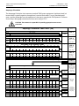
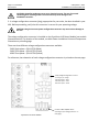
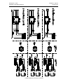
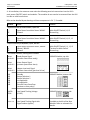
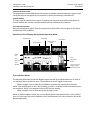
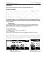
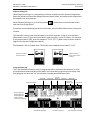
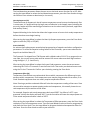
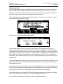
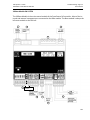
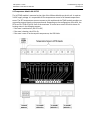
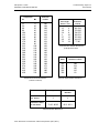
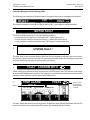
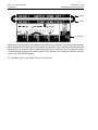
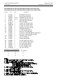
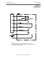
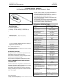
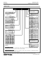
ITW Dynatec c. 2012 DYNAMELT S ASU Manual #20‐59P Page 2‐8 Description & Specifications Revised 4/12 Amperage Calculation The Amperage Calculation chart assumes standard ITW Dynatec equipment. Applicator head/ air heater width is typically equal to the applicator's service block width. For non‐standard equip‐ ment, read the amperage from the equipment's data tag or consult with ITW Dynatec's Customer Service Dept. Wire gauge calculation assumes wire rating of 75C. CAUTION: The customer is responsible for providing appropriate over‐current protection. PN 117249 Rev. A Amperage Calculation Chart DM‐S (V6) Model Amp ASU Size Amps DM‐ S 05/10 9.5 9.5 Total Length of All Hoses Feet m Amp 12 3.7 1.5 24 7. 3 3 36 11 4.5 48 14. 6 6 60 18.3 7.5 72 84 96 22 25.6 29.3 9 10.5 12 4 102 2 8 203 4 12 305 6 16 406 8 Inches mm Amp 0 0 0 2 51 2.5 4 102 5 6 152 7.5 20 508 10 24 610 12 28 711 14 32 813 16 Add up all hoses Enter Amps + 36 40 44 914 1016 1118 18 20 22 16 18 406 457 20 22.5 STEP 2 144 156 168 180 43.9 47.6 51.2 54.9 18 19.5 21 22.5 48 1219 24 52 1320 26 56 1422 28 60 1524 30 Total Width of All Air Heaters 8 10 12 14 203 256 305 356 10 12.5 15 17.5 Enter 9.5 Amps + 108 120 132 33 36.6 40.3 13.5 15 16.5 Total Width of All Applicator Heads Inches mm Amp STEP 1 Enter Amps + 20 508 25 22 24 26 559 610 660 27.5 30 32.5 28 711 35 Total Current for SINGLE PHASE AC Input Voltage STEP 3 Add up all applicators STEP 4 Add up all air heaters Enter Amps = STEP 5 Add up total amps STEP 6 Recommended Wire Gauge and Over‐Current Protection for Your Power Source SINGLE PHASE AC INPUT VOLTAGE SPECIFICATIONS Amp 20 23 26 29 32 35 38 41 44 47 50 53 AWG 10 10 8 8 8 8 8 8 6 6 6 6 2 2.5 2.5 4 4 4 6 6 10 10 10 10 10 mm 56 59 62 Contact Dynatec Amp @ Single PH 240V Wire Gauge 3‐ PHASE, 240VAC INPUT VOLTAGE SPECIFICATIONS Amp 12 13 15 17 18 20 22 24 25 27 29 31 32 34 36 AWG 12 12 12 10 10 10 10 10 10 8 8 8 8 8 8 2 2.5 2.5 2.5 2.5 2.5 2.5 2.5 2.5 2.5 4.0 4.0 4.0 4.0 6.0 6.0 mm Amp @ 3PH 240V 7 8 9 AWG 12 12 12 12 12 12 12 12 12 12 10 10 10 10 10 2 2.5 2.5 2.5 2.5 2.5 2.5 2.5 2.5 2.5 2.5 2.5 2.5 2.5 2.5 2.5 mm 10 11 12 13 14 15 16 17 18 19 20 21 STEP 7 Select your AC input voltage Wire Gauge 3‐ PHASE, 400VAC INPUT VOLTAGE SPECIFICATIONS Amp Find the column with your total single phase amperage in chart at left Amp @ 3PH 400V Wire Gauge Find the corresponding maximum amperage and wire gauge