1
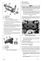
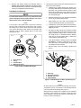
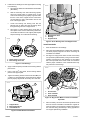
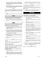
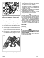
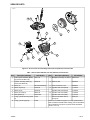
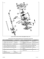
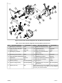
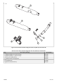
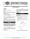
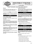
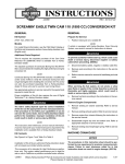
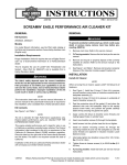
-J03825
REV. 2010-12-15
SCREAMIN' EAGLE TWIN CAM 103 (1690 CC) CONVERSION KIT
GENERAL
REMOVAL
Kit Number
29877-06 (Black) and 29876-06 (Silver)
These kits fit 2006 Touring models equipped with Electronic
Fuel Injection (EFI).
When servicing the fuel system, do not smoke or allow
open flame or sparks in the vicinity. Gasoline is extremely
flammable and highly explosive, which could result in
death or serious injury. (00330a)
Additional Parts and Tools Required
1.
This kit requires the separate purchase of the following parts
and tools which are available from a Harley-Davidson dealer.
Remove maxi-fuse. Refer to MAXI-FUSE INSTALLATION
in Service Manual.
2.
Remove existing air cleaner assembly. Discard filter element, backplate, and air cleaner cover insert but save
remaining parts. Refer to AIR CLEANER REMOVAL in
Service Manual.
3.
Remove existing exhaust system. Discard mufflers but
save remaining parts for kit installation. Refer to EXHAUST
SYSTEM REMOVAL in Service Manual.
4.
Remove engine from chassis following the instructions in
the Service Manual.
5.
Remove induction module. Refer to appropriate FUEL
INJECTION section in Service Manual.
6.
See Figure 1. Remove and save screw (with pilot sleeve)
to release fuel supply tube clamp.
Models
•
Camshaft/Crankshaft Sprocket Locking Tool (HD-43614)
•
Camshaft Remover/Installer (HD-43644)
•
Loctite® 243 (blue) 99642-97
Proper installation of this kit requires the use of Digital Technician™ at a Harley-Davidson dealer.
The rider's safety depends upon the correct installation
of this kit. Use the appropriate service manual procedures.
If the procedure is not within your capabilities or you do
not have the correct tools, have a Harley-Davidson dealer
perform the installation. Improper installation of this kit
could result in death or serious injury. (00333a)
is03165
NOTE
This instruction sheet references Service Manual information.
A Service Manual for your model motorcycle is required for
this installation and is available from a Harley-Davidson dealer.
Kit Contents
See Figure 13 to Figure 16, and Table 1 to Table 4.
NOTES
Installation of this kit by an authorized Harley-Davidson dealer
will not impact your limited vehicle warranty.
This Conversion kit is intended for High Performance applications only. This engine related performance part is legal for
sale or use in California on pollution controlled motor vehicles.
Engine related performance parts are intended for the experienced rider only.
Figure 1. Fuel Supply Tube Clamp Screw
7.
See Figure 2. Pull fuel supply tube (1) from fuel rail.
The Product Information Label contained in this kit is a
requirement of the California Air Resource Board (CARB)
emission regulation. Place the label on the right side of the
frame directly beneath the VIN sticker. This label is not required
outside the state of California.
-J03825
1 of 10
INSTALLATION
is03166
4
Inspect Cam Clearance
3
1.
1
3
1.
2.
3.
4.
A clearance problem between the new cam lobe and
crankcase housing may exist on certain older model
engines. Failure to maintain proper clearance could result
in severe engine damage. (00391b)
2
See Figure 4. Prior to starting assembly procedures, insert
new cams from kit into inner needle bearings (1) located
in the right side crankcase and check for a minimum of
0.030 in. clearance between highest lift point of cam lobes
and crankcase housing (2) with feeler gauges.
NOTE
If inadequate clearance is detected, crankcase housing must
be machined to provide 1.060 in. Radius clearance from center
of each cam bearing bore. After machining, recheck for minimum of 0.030 in. clearance.
Fuel supply tube
Sealing washer
O-ring
Screw (with pilot sleeve)
Figure 2. Fuel Supply Tube Assembly
is03157
8.
9.
Remove sealing washer (2) and O-ring (3) from fuel supply
tube. Remove second O-ring (3) from fuel rail bore. Discard sealing washer and O-rings.
1
See Figure 3. Pull fuel injectors (1) with attached fuel rail
from induction module. To overcome the resistance of the
bottom O-ring (2) on both fuel injectors, gently rock
assembly back and forth while pulling.
10. Remove spring clips (3) from fuel injectors. Pull fuel
injectors from fuel rail. To overcome the resistance of the
top O-ring (4) on both fuel injectors, gently rock assembly
back and forth while pulling.
2
11. Disassemble engine top end, engine bottom end, crankcase, and crankshaft. Refer to appropriate ENGINE sections in Service Manual.
1. Inner needle bearings
2. Crankcase housing clearance area
is03167
1
Figure 4. Inspect Cam Clearance
4
2
2.
3
Prior to engine assembly, inspect chain tensioner guides,
chain guide bracket, and balance chain. Refer to inspection
procedures in Service Manual.
Install Flywheel Assembly
See Figure 16. Install flywheel assembly (13) from kit following
the instructions in the Service Manual.
Remove Existing Cam Bearings
1.
2.
3.
4.
Fuel injector
O-ring, bottom
Clip, spring
O-ring, top
Figure 3. Fuel Injector Assembly
-J03825
NOTE
Both crank and primary cam sprocket flange screws are specially hardened while the flat washers are of a special diameter
and have ground surfaces. Therefore, use only the parts
provided in the Cam Drive Gear Retention Kit (25533-99A)
when performing this upgrade. The crank and primary cam
sprocket flange screws are not interchangeable.
1.
Remove existing crank and primary cam sprocket flange
screws and washers according to instructions in Service
Manual. Discard cam drive sprocket flange screws and
washers.
2.
Remove existing cam drive sprocket according to instructions in Service Manual.
2 of 10
3.
Remove and discard existing cam bearings. Refer to
ENGINE, BOTTOM END OVERHAUL Cam Support Plate,
Disassembly/Assembly (Camshaft, Camshaft Bearings)
section(s) of appropriate Service Manual.
1.
See Figure 5. Install rear cam roller bearing kit (Figure 15,
item 8) onto rear camshaft.
a.
Install O-ring in grinding relief groove. Groove is on
the splined end between the machined area and the
secondary cam sprocket. Exercise caution to avoid
stretching or breaking the O-ring. Since the O-ring is
not sold separately, damage will require purchase of
new roller bearing kit.
b.
Slide thrust washer down rear camshaft until centered
over O-ring in grinding relief position.
c.
Slide bearing inner race down rear camshaft until
contact is made with shoulder of machined area.
d.
Install primary cam sprocket spacer and sprocket on
camshaft, and secure using thicker flat washer and
long flange screw.
e.
See Figure 6. Wrap a shop rag (1) around camshaft
to get a firm grip and also to protect hand from sharp
edges of sprocket. Using a 9/16 in. box wrench (2),
turn flange screw in a clockwise direction. Bearing
inner race (3) is fully installed when it makes firm
contact with the thrust washer (4).
f.
Verify thrust washer is locked in place and cannot
be rotated. If necessary, install shaft in vise using
brass jaw inserts, and further tighten flange screw
until desired result is achieved.
g.
Remove flange screw, flat washer, sprocket, and
spacer.
Install New Cam Bearings
To center thrust washer, be sure o-ring is installed in relief
groove. Damage to bearing cage and engine can occur if
thrust washer is not centered. (00473b)
NOTE
If not enough of the splined shaft is exposed to install the
sprocket, leave out the spacer and proceed to Step 1e. Once
the bearing inner race has been started onto the machined
area, remove the flange screw, washer, and sprocket, then
assemble using the spacer. Repeat Step 1e to fully install
bearing inner race.
is03134
2
3
is03135
2
4
3
1
1.
2.
3.
4.
Roller bearing
O-ring
Thrust washer
Bearing inner race
4
1
Figure 5. Rear Cam Roller Bearing Kit
1.
2.
3.
4.
Shop rag
Box wrench, 9/16 in.
Bearing inner race
Thrust washer
Figure 6. Install Bearing Inner Race (with O-Ring and
Washer)
NOTES
Be aware that the front and rear cam bearings are not interchangeable. The rear cam utilizes a roller bearing while the
front cam utilizes a ball bearing (See Figure 7).
Bearing fit may be a light press or slightly loose fit. If deemed
necessary, clean bearing O.D. and apply Loctite 243 (blue)
before installation, but exercise caution to avoid getting compound on rollers or bearing I.D.
-J03825
3 of 10
2.
Install new cam bearings into cam support plate according
to the following:
a.
See Figure 8. Obtain the Camshaft Remover/Installer
(HD-43644).
b.
With the secondary cam chain side facing upward,
place cam support plate on support block, so that
outer races of bearings are properly supported. Note
that one corner of the support block is contoured to
accommodate the chain guide blocks cast into the
front of the support plate.
c.
Center new bearing over bearing bore with the
lettered side up. Slide pilot shaft of bearing driver
through bearing into hole of support block.
d.
See Figure 9. Center bearing driver under ram of
arbor press. Press on driver until bearing makes firm
contact with counterbore in cam support plate. Repeat
Steps 2a through 2c to install second bearing.
is03138
1
3
1. Bearing/pilot driver
2. Bearing
3. Support block
is03136
1
2
2
Figure 9. Press Bearings into Cam Support Plate
Install Camshafts
1.
Start camshafts into cam bearings.
2.
Place cam support plate back on support block, if removed.
The block properly supports inner races of bearings as
camshafts are installed.
3.
See Figure 10. Align punch marks on teeth of secondary
cam sprockets (outboard faces). Using a colored marker,
carefully mark the punch mark locations on the inboard
side of the sprocket teeth. These marks are needed to
observe proper orientation of the camshafts when they
are pressed into the bearings.
1. Roller bearing, rear cam
2. Ball bearing, front cam
Figure 7. Cam Bearings
3.
Apply Loctite 243 (blue) to threads of four bearing retainer
plate screws.
4.
Using a T20 Torx® drive head, secure bearing retainer
plate to cam support plate.
5.
Tighten four bearing retainer screws to 20-30 in-lbs (2.33.4 Nm) in a crosswise pattern. Verify that hole in retainer
plate is properly aligned with secondary cam chain oiler.
is03139
1
is03137
2
1
3
3
2
1. Punch marks
2. Front camshaft
3. Rear camshaft
Figure 10. Align Punch Marks on Teeth of Camshaft
Sprockets
4.
1. Support block
2. Bearing/pilot driver
3. Camshaft driver
Figure 8. Camshaft Remover/Installer
-J03825
Place secondary cam chain around the sprockets of both
the front and rear camshafts. To maintain the original direction of rotation, be sure that the colored mark placed on
the chain link during disassembly is facing opposite the
cam support plate during installation.
4 of 10
5.
6.
Orient the camshafts so that they are positioned on
opposite ends of the chain, and then verify that the colored
marks placed on the inboard side of the sprocket teeth
are still in alignment.
Maintaining the position of the camshafts on the chain with
the colored marks in alignment, place the sprocket ends
of the camshafts into the bearings.
NOTE
Be sure not to mix camshafts during the press procedure. The
rear camshaft, which can be identified by the splined shaft,
must go into the roller bearing at the rear of the cam support
plate.
7.
Place cup of camshaft driver over end of front camshaft
only.
During press procedure, keep tensioner shoe clear of chain
to prevent damage to tensioner assembly. (00474b)
8.
section(s) in appropriate Service Manual. Use spacers
provided in kit in place of those listed in Service Manual.
NOTES
Verify alignment at crank and primary cam sprocket punch
marks as described in Service Manual.
Verify alignment at crank and primary cam sprocket faces. Use
spacers provided in kit to maintain alignment at plus (+) or
minus (-) 0.01 in.
3.
Apply threadlocker to maintain clamp load on flange bolt.
A loose flange bolt can cause engine failure, which could
result in death or serious injury. (00476c)
4.
Center end of front camshaft under ram and slowly apply
pressure to driver just to start front camshaft into bearing
I.D.
Be sure rear camshaft is aligned during press procedure.
Misalignment can cause inner race to catch on bearing
rollers resulting in bearing damage. (00475b)
9.
Slowly apply pressure to driver on front camshaft, while
wiggling rear camshaft as necessary to guide inner race
between bearing rollers.
10. When inner race on rear cam is started into roller bearing,
apply pressure to driver until front camshaft is fully seated.
If necessary, keep finger pressure at top of rear camshaft
so that assembly remains square and inner race moves
to installed position in roller bearing.
11. After installing new cams, check for proper cam to cam
timing using straightedge along punch marks as described
in Service Manual.
12. Install retaining ring from kit in groove at end of front
camshaft.
NOTES
Inspect cam needle bearings in crankcase and replace if
necessary.
Replace oil pump to cam plate O-ring (Figure 15, item 2) and
cam plate to crankcase O-ring (Figure 15, item 6).
Install Cam Support Plate
Install cam plate according to ENGINE, BOTTOM END
OVERHAUL Cam Support Plate, Disassembly/Assembly
instructions in applicable Service Manual.
See Figure 15. Use cam flange screw (12), washer (11),
crank flange screw (10), and washer (9) from kit.
5.
Install new flange screws and washers as follows:
a.
Verify threads are clean and free from oil then apply
Loctite Primer 7649.
b.
Apply Loctite® 262 (red) 94759-99 to threads of flange
screws.
c.
Apply a thin film of clean H-D 20W50 engine oil to
both sides of flat washers.
d.
Start flange screw with flat washer to secure crank
sprocket to end of crankshaft.
e.
Start flange screw with flat washer to secure primary
cam sprocket to end of camshaft.
f.
See Figure 11. Position Camshaft/Crankshaft
Sprocket Locking Tool (HD-42314) between the crank
and primary cam sprockets to prevent rotation. The
handle of the tool is stamped "Cam" and "Crank" for
proper orientation.
g.
Tighten crank and primary cam sprocket flange
screws to 15 ft-lbs (20.3 Nm).
h.
Loosen each flange screw one full turn.
i.
Tighten crank flange screw to 24 ft-lbs (32.5 Nm) final
torque value.
j.
Tighten primary cam sprocket flange screw to 34 ftlbs (46.0 Nm) final torque value.
k.
Remove sprocket locking tool and follow instructions
in Service Manual for unloading primary cam chain
tensioner.
Install cam cover according to ENGINE, BOTTOM END
OVERHAUL, Cam Support Plate, Disassembly/Assembly
instructions in applicable Service Manual.
NOTE
Replace cam cover gasket (Figure 15, item 3).
Install Rear Cam Sprocket, Crank Sprocket, and
Primary Cam Chain
1.
Apply a thin film of clean H-D 20W50 engine oil to the
splines of the rear cam.
2.
Install splined sprocket onto rear camshaft. Refer to
ENGINE, BOTTOM END OVERHAUL Cam Support Plate,
Disassembly/Assembly (Camshaft, Camshaft Bearings)
-J03825
5 of 10
is03140
7.
See Figure 2. Slide O-ring (3) from kit down shorter neck
of the fuel supply tube (1) until it contacts the collar. Slide
sealing washer (2) from kit down tube until it contacts Oring. Install second O-ring (3) in fuel rail bore.
8.
See Figure 1. Push fuel supply tube into fuel rail bore until
clamp is seated on round step of fuel rail. Install screw
(with pilot sleeve) previously removed and tighten to 90110 in-lbs (10.2-12.4 Nm).
9.
Install induction module. Refer to appropriate FUEL
INJECTION section in Service Manual.
10. Install clutch diaphragm spring (Table 2, item 15) from kit
following the instructions in the Service Manual.
Install Mufflers and Air Cleaner
NOTE
Figure 11. Camshaft/Crankshaft Sprocket Locking Tool
Install Engine, Fuel Injection, and Clutch Spring
1.
Assemble remaining engine components. Refer to appropriate ENGINE sections in Service Manual.
2.
Install engine in chassis following the instructions in the
Service Manual.
3.
See Figure 3. Apply a thin coating of clean engine oil to
O-rings (2, 4) from kit on fuel injectors (1).
4.
Push electrical connector side of fuel injectors into fuel
rail.
5.
See Figure 12. With the concave side toward the fuel rail,
install spring clip into slot on fuel injector. In the installed
position, openings (1) in side of clip engage lip (2) of fuel
rail, while fork (3) at back of clip captures fuel injector tab
(4).
6.
Rotate fuel injectors, so that the electrical connectors are
on the outboard side. Push fuel injectors into the induction
module bores until fuel rail tab (5) engages machined slot
at top of induction module.
When installing the exhaust system, first install the rear and
front cylinder exhaust pipes, shields, and related components.
1.
See Figure 16. Install exhaust system using mufflers (1,
2) from kit and parts previously removed. Refer to
EXHAUST SYSTEM INSTALLATION in Service Manual.
2.
See Figure 13. Install air cleaner assembly using backplate
(9), filter element (10), and air cleaner cover insert (11)
from kit. Refer to AIR CLEANER INSTALLATION in Service Manual.
Final Assembly
Install maxi-fuse. Refer to MAXI-FUSE INSTALLATION in
Service Manual.
Recalibrate ECM
You must recalibrate the ECM when installing this kit.
Failure to properly recalibrate the ECM can result in severe
engine damage. (00399b)
Download the new ECM calibration using the Digital Technician™ at a Harley-Davidson dealer.
is03168
2
3
1
4
1.
2.
3.
4.
5.
5
Opening
Lip
Fork
Injector tab
Rail tab
Figure 12. Installation of Spring Clips
-J03825
6 of 10
SERVICE PARTS
is03171
12 13
9
10
6
11
1
3
5
7
4
2
8
5
Figure 13. Service Parts: Screamin Eagle Twin Cam 103 (1690 CC) Conversion Kit
Table 1. Service Parts: SE Twin Cam 103 (1690 CC) Conversion Kit
Item
1
Description (Quantity)
Part Number
Item
Description (Quantity)
Part Number
1550 Cylinder assembly (Black)
(2) (used in Kit 29877-06)
16547-99
9
Backplate assembly, air cleaner
29697-02A
Cylinder assembly (Silver) (2)
(used in Kit 29876-06)
16548-99
10
Element, filter
29509-06
2
Piston (2)
Not Sold Separately
11
Insert, air cleaner cover
29480-03
3
Piston ring set (2)
21918-99
12
Cylinder head, front (black)
17150-06
4
Piston pin (2)
22132-99
Cylinder head, front (silver)
17149-06
5
Piston pin circlip (4)
22097-99
Cylinder head, rear (black)
17152-06
6
Head gasket (2)
16787-99A
Cylinder head, rear (silver)
17151-06
7
O-ring, cylinder deck ring dowel
(2)
11273
Piston kit (includes items 2
through 5)
22421-03
8
O-ring, cylinder spigot (2)
11256
-J03825
13
--
Notes: Do not install O-ring (item 7) to top cylinder dowels.
Refer to 2006 FLHTCUSE Parts Catalog, part number 9942806 for individual components of cylinder head assemblies
(items 11 and 12).
7 of 10
is03151b
2
8
6
10
9
4
7
5
3
1
Figure 14. Service Parts: Screamin' Eagle Big Bore Stage 1 Kit
Table 2. Service Parts: Screamin' Eagle Twin Cam 103 (1690 CC) Conversion Kit
Item
Description (Quantity)
Part Number
Item
Description (Quantity)
Part Number
1
Gasket, rocker cover base (2)
16719-99A
10
Baffle assembly (2)
26500002
2
Gasket, rocker cover top (2)
17386-99A
11
Product information label (Not
Shown)
Not Sold Separately
3
Gasket, tappet cover (2)
18635-99B
12
Seal, exhaust (Not Shown)
17048-98
4
O-ring, middle push rod cover (4) 11132
13
Seal, EFI intake (2) (Not Shown) 26995-86B
5
O-ring, lower push rod cover (4)
11145
14
Seal, map sensor (Not Shown)
11291
6
O-ring, upper push rod cover (4) 11293
15
Spring, clutch diaphragm (Not
Shown)
37951-98
7
O-ring, rocker arm support (2)
11270
--
Breather assembly (includes items 17025-03A
8 through 10)
8
Bolt (4)
4400
9
Breather assembly
17025-03A
-J03825
8 of 10
is03176
19
7
6
8
18
15
2
14
13
7
16
5
20
4
17
1
11
12
3
1
10
9
Figure 15. Service Parts: Screamin' Eagle Twin Cam 103 (1690 CC) Conversion Kit
Table 3. Service Parts: Screamin' Eagle Twin Cam 103 (1690 CC) Conversion Kit
Item
Description (Quantity)
Part Number
Item
Description (Quantity)
Part Number
1
Retaining ring, camshaft (2)
11031
12
Capscrew, flanged (rear cam)
996
2
O-ring, oil pump to cam plate
11286
13
Flywheel assembly
23740-03B
3
Gasket, cam cover
25244-99A
14
Seal, main bearing oil
12068
4
Retaining ring, camshaft
11494
15
Washer, thrust sprocket shaft
main bearing
8972
5
Ball bearing, front camshaft
8990A
16
Bearing, main (2)
24604-00D
6
O-ring, cam plate to crankcase (2) 11301
17
Retaining ring, internal
35114-02
7
Camshaft kit
18
O-ring, crankcase ring dowel (2) 26432-76A
8
Roller bearing kit, rear camshaft 8983
19
O-ring, piston cooling (2)
11140
9
Washer (crank) (2)
Not Sold Separately
20
O-ring, CPS
11289A
10
Capscrew, flanged (crank)
Not Sold Separately
21
Loctite 262 (red), 0.5 ml packet
(Not Shown)
Not Sold Separately
11
Washer (rear cam)
6294
-J03825
25376-03
Notes: Items 9 and 10 are only available as part of Cam Drive
Retention Kit 25533-99A. Loctite (item 21) is only available in
6 ml tube, part number 94759-99.
9 of 10
is03169
2
1
3
4
5
3
Figure 16. Service Parts: Screamin' Eagle Twin Cam 103 (1690 CC) Conversion Kit
Table 4. Service Parts: Screamin' Eagle Twin Cam 103 (1690 CC) Conversion Kit
Item
Description (Quantity)
Part Number
1
Muffler assembly, R.H. (with end caps)
66077-06
2
Muffler assembly, L.H. (with end caps)
66012-06
3
O-ring, fuel supply tube (2)
27680-06
4
Sealing washer, fuel supply tube
27681-06
5
Fuel injector (2)
27709-06
6
Element, filter (Not Shown)
29509-06
-J03825
10 of 10