1
14-2
F U E L SYSTEM-
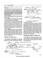
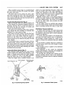
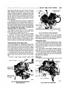
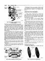
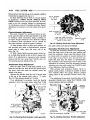
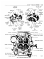
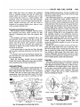
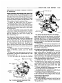
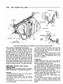
stainless steel cup fastened over a p o r t i n the manifold (Fig. 1).
The stainless steel w e l l cups are held i n place by
choke retainer bolts. A steel-asbestos gasket seals the
exhaust gas w i t h i n the manifold. Loosening or removing the choke retainer bolts will allow exhaust gases
to escape into the engine compartment. DO NOT RUN
T H E ENGINE WITHOUT THE CHOKE FIRMLY
BOLTED T O T H E M A N I F O L D . FIRE OR H E A T D A M A G E M A Y OCCUR.
W h e n installing the steel w e l l cup, make certain the
gasket is i n good condition and is i n place to prevent
exhaust leakage.
Do not lubricate any of the choke parts or the cont r o l u n i t . This causes d i r t to accumulate, and w o u l d
result i n b i n d i n g of the choke mechanism.
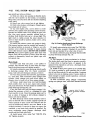
The choke c o n t r o l u n i t is accurately adjusted when
first assembled. Under n o r m a l servicing do NOT
change the setting or disassemble the c o n t r o l u n i t .
I f however, t h e setting has been disturbed, reset as
follows: Loosen locknut and t u r n shaft w i t h screwd r i v e r u n t i l index m a r k on disc is i n alignment w i t h
correct m a r k o n the frame. H o l d i n this position w i t h
screwdriver while t i g h t e n i n g n u t , (Refer to Specifications f o r indexing).
A l l the carburetors referred t o i n the F u e l System
are either equipped f o r use w i t h a Cleaner A i r System
(C.A.S.) or an Evaporation Control System, (E.C.S.) depending on the area i n which the vehicle is t o be used.
The servicing procedures covering these carburetors
are nearly identical. Differences between the t w o
types of carburetors are covered (where applicable)
i n the service procedures.
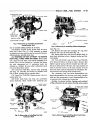
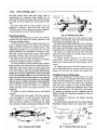
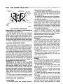
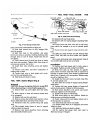
C L E A N E R AIR S Y S T E M (C.A.S.)
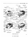
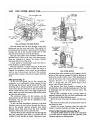
The cleaner air system consists of a special air
cleaner, breather cap, ventilation valve, carburetor,
distributor and various other automatic c o n t r o l de-
CARBURETOR
CRANKCASE
VENTILATION V A L V E
AIR CLEANER
BOWL VENT V A L V E
CLEANER
TO C A P HOSE
BREATHER C A P
VENT V A L V E
TO CARBURETOR HOSE
CRANKCASE
(VAPOR STORAGE AREA)
PY598
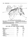
Fig. 2—Cleaner Air System (C.A.S.J
vices, (Fig. 2) as required.
The function of the cleaner air system is to reduce
the u n b u r n e d hydro-carbons emitted by t h e vehicle's
engine. Fresh a i r is d r a w n i n t o the a i r cleaner, f o r consumption by the engine. A p o r t i o n of this fresh a i r is
diverted t h r o u g h a hose to the breather cap and i n t o
the crankcase. Manifold vacuum causes crankcase
vapors (including fresh a i r and u n b u r n e d hydro-carbons) to flow t h r o u g h the crankcase ventilation valve
to t h e base (or t h r o t t l e body) of the carburetor. These
vapors are joined w i t h the f u e l m i x t u r e i n t h e intake
manifold and are delivered i n t o the combustion chamber, f r o m w h i c h they are ejected as essentially completely burned exhaust products.
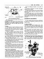
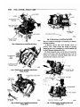
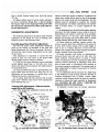
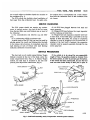
EVAPORATION CONTROL S Y S T E M (E.C.S.)
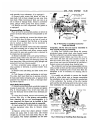
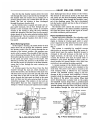
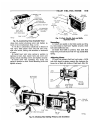
The evaporation c o n t r o l system consists of t h e
C.A.S. system plus, a special vented f u e l tank, separator, fuel tank vapor tube, breather cap, enclosed
b o w l vent valve, a vacuum pressure relief f u e l t a n k
cap and hoses (Fig. 3).
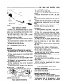
PY599
Fig. 3—Evaporation Control System
(EX.S.)