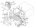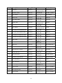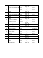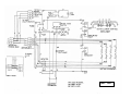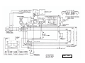
1
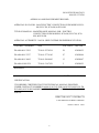
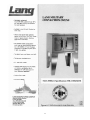
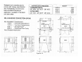
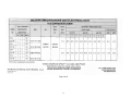
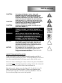
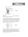
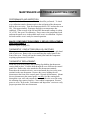
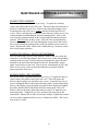
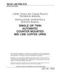
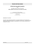
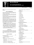
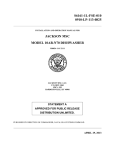
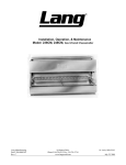
S6161-KW-FSE-010/34931
0910-LP-327-9700
OPERATION AND SERVICE MANUAL
FOR
SHIPBOARD ELECTRIC CONVECTION OVENS
MODEL NUMBERS ECO-6M, ECO-7M, ECO-8M, and ECO9M
LANG MANUFACTURING COMPANY
6500 MERRILL CREEK PARKWAY
EVERETT, WA 98203
FSCM 34931
DISTRIBUTION STATEMENT
THIS PUBLICATION IS REQUIRED FOR OFFICIAL USE OR FOR
ADMINISTRATIVE OR OPERATIONAL PURPOSES. DISTRIBUTION IS LIMITED
TO U.S. GOVERNMENT AGENCIES ONLY. OTHER REQUESTS FOR THIS
DOCUMENT MUST BE REFERRED TO COMMANDER, NAVAL SEA SYSTEMS
COMMAND, SEA 09, WASHINGTON, DC 20362
SUPERCEDURE NOTICE
S6161-KW-FSE-010/34931 DATED JANUARY 2006
CANCELS AND SUPERCEDES S6161-KW-FSE-010/34931
DATED MAY 1999
AND ALL CHANGES THERETO
1
MANUAL SUPPLEMENT FOR MARINE EQUIPMENT
THIS EQUIPMENT IS APPROVED FOR INSTALLATION ONLY ON
VESSELS GREATER THAN 65 FEET IN LENGTH IN
ACCORDANCE WITH USCG REGULATIONS IN TITLE 46 CFR 110113.
ANY WIRING USED IN THE INSTALLATION OF THIS APPLIANCE
MUST BE STRANDED COPPER.
2
S6161-KW-FSE-010/34931
JANUARY 2006
IDENTIFYING TECHNICAL PUBLICATION SHEET
1. IDENTIFICATION DATA: LANG MFG. CO. MODELS ECO-6M, ECO-7M,
ECO-8M, & ECO-9M.
2. PURPOSE: THIS TECHNICAL PUBLICATION IS ISSUED FOR THE PURPOSE
OF IDENTIFYING AN AUTHORIZED TECHNICAL MANUAL FOR NAVY USE
AND FOR PROVIDING SUPPLEMENTAL TECHNICAL INFORMATION.
A. MANUFACTURER: LANG MFG. CO.
B. CONTRACT NUMBER: DLA400-91-M-5159
C. EQUIPMENT: ELECTRIC CONVECTION OVEN, MODEL # ECO-6M, ECO7M, ECO-8M, & ECO-9M.
D. REQUISITION NUMBER: NOT REFERENCED
E. NATIONAL STOCK NUMBER (NSN): 7310-01-314-7939
F. TITLE: MAINTENANCE MANUAL FOR ELECTRIC CONVECTION OVEN
ECO-6M, ECO-7M, ECO-8M, & ECO-9M
G. DATE OF PUBLICATION: JANUARY 2006
H. PREPARING ACTIVITY: DEFENSE GENERAL SUPPLY CENTER
I. APPLICABLE TMCR NUMBER: NDMS 880393-000
J. EXTENT OF PROPOSED SUPPLEMENTAL DATA (10% MAXIMUM): 1%
K. LIST OF TECHNICAL MANUAL FOR THIS EQUIPMENT PROCURED
UNDER ANOTHER CONTACT:
3. ADDITIONAL COPIES: ADDITIONAL COPIES ARE AVAILABLE FROM:
NAVAL PUBLICATION AND FORMS CENTER
5801 TABOR AVENUE
PHILADELPHIA, PA 19120-5099
4. COVER: THE TECHNICAL MANUAL OUTSIDE COVER SHALL CONTAIN
THE FOLLOWING STATEMENTS:
PUBLISHED BY DIRECTION OF COMMANDER, NAVAL SEA SYSTEMS
COMMAND
THIS PUBLICATION IS REQUIRED FOR OFFICIAL USE OR FOR
ADMINISTRATIVE OR OPERATIONAL PURPOSES. DISTRIBUTION IS LIMITED
TO U.S. GOVERNMENT AGENCIES ONLY. OTHER REQUESTS MUST BE
REFERRED TO COMMANDER, NAVAL SEA SYSTEMS COMMAND, SEA 09,
WASHINGTON, DC 20362.
3
S6161-FW-FSE-010/34931
0910-LP-327-9700
APPROVAL AND PROCUREMENT RECORD
APPROVAL DATA FOR: LANG ELECTRIC CONVECTION OVEN MODELS ECO6M, ECO-7M, ECO-8M, & ECO-9M.
TITLE OF MANUAL: MAINTENANCE MANUAL FOR: ELECTRIC
CONVECTION OVEN MODELS: ECO-6M, ECO-7M, ECO8M, & ECO-9M.
APPROVAL AUTHORITY: NAVAL SHIP SYSTEMS ENGINEERING STATION
CONTRACT NUMBER
NSN
# OF UNITS
APL/CID
DLA400-86-C-5292
7310-01-227-8214
58
430280135
DLA400-88-C-5327
7310-01-277-4105
97
430280144
DLA400-89-C-0442
7310-01-290-0463
13
430280147
DLA400-91-M-5159
7310-01-314-7939
5
430280155
REMARKS:
DATE: JANUARY 2006
CERTIFICATION:
IT IS HEREBY CERTIFIED THAT THE TECHNICAL MANUAL PROVIDED
UNDER CONTRACT NUMBER DLA400-91-M-5159 FOR LANG ECO-6M, ECO-7M,
ECO-8M, & ECO-9M HAS BEEN APPROVED BY THE APPROVAL DATA SHOWN
ABOVE:
______________________________
DIRECTOR, GOV’T CONTRACTS
LANG MANUFACTURING COMPANY
FSCM / CAGE #: 34931
4
CHANGE RECORD
Change no.
Date
Title and/or Brief Description
5
Signature of
Validating Officer
TABLE OF CONTENTS
CHAPTER
PAGE
1.
TABLE OF CONTENTS ............................................................................... 6
2.
LIST OF ILLUSTRATIONS.......................................................................... 7
3.
READ FIRST ................................................................................................. 8
4.
SPECIFICATIONS ........................................................................................ 11
5.
EQUIPMENT DESCRIPTION ...................................................................... 14
6.
INSTALLATION ........................................................................................... 16
7.
OPERATION.................................................................................................. 18
8.
MAINTENANCE & TROUBLESHOOTING PROCEDURES .................... 19
9.
PARTS LIST .................................................................................................. 24
10. WIRING DIAGRAMS ................................................................................... 26
6
LIST OF ILLUSTRATIONS
FIGURE #
1
1A
TITLE OF ILLUSTRATION
Picture of Oven
PAGE #
11
Specifications
12 & 13
2
Leg Installation
17
3
Stacking Instructions
17
4
Exploded View
23
5
Wiring Diagram 208/240 VAC
26
6
Wiring Diagram 440 VAC
27
7
IMPORTANT
CAUTION:
CAUTION:
CAUTION:
DANGER:
WARNING:
NOTICE:
NOTICE:
NOTICE:
CAUTION:
CAUTION:
READ FIRST
THE OVEN IS EXTREMELY HEAVY. FOR SAFE
HANDLING, INSTALLER SHOULD OBTAIN HELP AS
NEEDED, OR EMPLOY APPROPRIATE MATERIALS
HANDLING EQUIPMENT (SUCH AS A FORKLIFT,
DOLLY, OR PALLET JACK) TO REMOVE THE UNIT
FROM THE SKID AND MOVE IT TO THE PLACE OF
INSTALLATION.
ANY STAND, COUNTER OR OTHER DEVICE ON
WHICH OVEN WILL BE LOCATED MUST BE
DESIGNED TO SUPPORT THE WEIGHT OF THE
OVEN(S).
SHIPPING STRAPS ARE UNDER TENSION AND CAN
SNAP BACK WHEN CUT.
THIS APPLIANCE MUST BE GROUNDED AT THE
TERMINAL PROVIDED. FAILURE TO GROUND THE
APPLIANCE COULD RESULT IN ELECTROCUTION
AND DEATH.
INSTALLATION OF THE UNIT MUST BE DONE BY
PERSONNEL QUALIFIED TO WORK WITH
ELECTRICITY AND PLUMBING. IMPROPER
INSTALLATION CAN CAUSE INJURY TO
PERSONNEL AND/OR DAMAGE TO EQUIPMENT.
UNIT MUST BE INSTALLED IN ACCORDANCE WITH
ALL APPLICABLE CODES.
The data plate is located on the door of the oven. The
oven voltage, wattage, serial number, wire size, and
clearance specifications are on the data plate. This
information should be carefully read and understood
before proceeding with the installation.
The installation of any components such as a vent
hood, grease extractors, fire extinguisher systems,
must conform to their applicable National, State and
locally recognized installation standards.
During the first few hours of operation you may
notice a small amount of smoke coming off the oven,
and a faint odor from the smoke. This is normal for a
new oven and will disappear after the first few hours
of use.
ALWAYS KEEP THE AREA NEAR THE APPLIANCE
FREE FROM COMBUSTIBLE MATERIALS.
KEEP FLOOR IN FRONT OF EQUIPMENT CLEAN
AND DRY. IF SPILLS OCCUR, CLEAN IMMEDIATELY,
TO AVOID THE DANGER OF SLIPS OR FALLS.
8
IMPORTANT
IMPORTANT
WARNING:
CAUTION:
NOTICE:
WARNING:
CAUTION:
READ FIRST
KEEP WATER AND SOLUTIONS OUT OF CONTROLS.
NEVER SPRAY OR HOSE CONTROL CONSOLE,
ELECTRICAL CONNECTIONS, ETC.
MOST CLEANERS ARE HARMFUL TO THE SKIN, EYES,
MUCOUS MEMBRANES AND CLOTHING.
PRECAUTIONS SHOULD BE TAKEN TO WEAR RUBBER
GLOVES, GOGGLES OR FACE SHIELD AND
PROTECTIVE CLOTHING. CAREFULLY READ THE
WARNING AND FOLLOW THE DIRECTIONS ON THE
LABEL OF THE CLEANER TO BE USED.
Service on this, or any other, LANG appliance must be
performed by qualified personnel only. Consult your
authorized service station directory or call the factory at
1-800-224-LANG (5264), or WWW.LANGWORLD.COM
For the service station nearest you.
BOTH HIGH AND LOW VOLTAGES ARE PRESENT
INSIDE THIS APPLIANCE WHEN THE UNIT IS
PLUGGED/WIRED INTO A LIVE RECEPTACLE. BEFORE
REPLACING ANY PARTS, DISCONNECT THE UNIT
FROM THE ELECTRIC POWER SUPPLY.
USE OF ANY REPLACEMENT PARTS OTHER THAN
THOSE SUPPLIED BY LANG OR THEIR AUTHORIZED
DISTRIBUTORS CAN CAUSE BODILY INJURY TO THE
OPERATOR AND DAMAGE TO THE EQUIPMENT AND
WILL VOID ALL WARRANTIES.
9
IMPORTANT
LANG MANUFACTURING COMPANY
MANUAL FOR MODEL ECO
ELECTRIC CONVECTION OVENS
ISSUE DATE JANUARY 2006
LANG MANUFACTURING COMPANY
6500 MERRILL CREEK PARKWAY
EVERETT, WA 98203
CONVECTION OVENS PER: MIL-0-0043633 E
MIL SPEC
Type I, Size 1
Type I, Size 1 N.S.A. *
Type I, Size 2
Type I, Size 2 N.S.A. *
Type II, Size 1
Type II, Size 1 N.S.A. *
Type II, Size 2
Type II, Size 2 N.S.A. *
LANG MODEL NUMBER
SPECIFIC NSN
ECO-7
ECO-7M
7310-01-290-0463
ECO-6
ECO-6M
7310-01-314-7939
ECO-9
7310-01-230-0559
ECO-9M
7310-01-277-4105
ECO-8
ECO-8M
7310-01-227-8214
* N.S.A. for “Naval Shipboard Application”. All components will fit through a 26” X
66” watertight door.
10
Figure # 1
11
Figure # 1A
12
Figure # 1A
13
EQUIPMENT DESCRIPTION
INTRODUCTION
This manual contains the necessary information to install, operate, maintain,
and service the Lang model ECO convection ovens.
Replacement parts should be genuine Lang parts. Failure to use genuine
Lang replacement parts may result in malfunction of the appliance or
possible injury to the contractor or service technician.
PURPOSE AND FUNCTION
Convection ovens constantly circulate air over the product. This removes a
layer of moisture and cool air from around the product. This allows heat to
penetrate the product more quickly. Cooking times are shortened and
cooking temperatures are reduced.
CAPABILITIES
This convection oven is suitable for cooking all types of products requiring
baking or roasting.
ENVIRONMENTAL REQUIREMENTS
The following minimum spacing from combustible surfaces must be
maintained: Sides – 2 inches, Back – 2 inches
ITEMS FURNISHED (Listed by Model Number)
Model ECO-6 or ECO-6M
1 ea. Oven, Type I, Size 2
4 ea. Legs
16 ea. 3/8 – 16 x 5/8 Bolts (For mounting legs)
16 ea. 3/8 – 16 Hex Nuts (For mounting legs)
32 ea. Washers (For mounting legs)
2 ea. Rack Slides, Extra Deep
5 ea. Racks, Extra Deep
2 ea. Manuals, Technical
Model ECO-7 or ECO-7M
1 ea. Oven, Type I, Size 1
4 ea. Legs
16 ea. 3/8 – 16 x 5/8 Bolts (For mounting legs)
16 ea. 3/8 – 16 Hex Nuts (For mounting legs)
32 ea. Washers (For mounting legs)
2 ea. Rack Slides, Standard Depth
5 ea. Racks, Standard Depth
2 ea. Manuals, Technical
14
EQUIPMENT DESCRIPTION CONT’D
Model ECO-8 or ECO-8M
2 ea. Oven, Type II, Size 2
4 ea. Legs
16 ea. 3/8 – 16 x 5/8 Bolts (For mounting legs)
16 ea. 3/8 – 16 Hex Nuts (For mounting legs)
32 ea. Washers (For mounting legs)
4 ea. Rack Slides, Extra Deep
10 ea. Racks, Extra Deep
2 ea. Manuals, Technical
1 ea. Stacking Kit
Model ECO-9 or ECO-9M
2 ea. Oven, Type II, Size 1
4 ea. Legs
16 ea. 3/8 – 16 x 5/8 Bolts (For mounting legs)
16 ea. 3/8 – 16 Hex Nuts (For mounting legs)
32 ea. Washers (For mounting legs)
4 ea. Rack Slides, Standard Depth
10 ea. Racks, Standard Depth
2 ea. Manuals, Technical
1 ea. Stacking Kit
ITEMS REQUIRED
An adequate supply of wire suitable for the loads and application specified on
the data sheet must be provided. The data sheet is on Page 4 of this manual.
TOOLS AND TEST EQUIPMENT REQUIRED
For Installation:
1 set – Open End Wrenches
1
– Flat Blade Screwdriver
1
– Phillips Screwdriver
1
– Wire Cutter/Stripper
1 – AMP Probe
1
– Voltmeter
1
– Drill
4
– #27 Drill Bits
For Service: All of the above plus –
1
– Needle Nose Pliers
1
– Crimping Pliers
1
– Allen Wrench Set
1
– Temperature Meter
1
– Very Small Flat Blade Screwdriver
1 – #10 Square Drive Screwdriver
15
INSTALLATION
CAUTION:
CAUTION:
CAUTION:
DANGER:
WARNING:
NOTICE:
NOTICE:
THE OVEN IS EXTREMELY HEAVY. FOR SAFE
HANDLING, INSTALLER SHOULD OBTAIN HELP AS
NEEDED, OR EMPLOY APPROPRIATE MATERIALS
HANDLING EQUIPMENT (SUCH AS A FORKLIFT, DOLLY,
OR PALLET JACK) TO REMOVE THE UNIT FROM THE
SKID AND MOVE IT TO THE PLACE OF INSTALLATION.
ANY STAND, COUNTER OR OTHER DEVICE ON WHICH
OVEN WILL BE LOCATED MUST BE DESIGNED TO
SUPPORT THE WEIGHT OF THE OVEN(S).
SHIPPING STRAPS ARE UNDER TENSION AND CAN
SNAP BACK WHEN CUT.
THIS APPLIANCE MUST BE GROUNDED AT THE
TERMINAL PROVIDED. FAILURE TO GROUND THE
APPLIANCE COULD RESULT IN ELECTROCUTION AND
DEATH.
INSTALLATION OF THE UNIT MUST BE DONE BY
PERSONNEL QUALIFIED TO WORK WITH ELECTRICITY
AND PLUMBING. IMPROPER INSTALLATION CAN
CAUSE INJURY TO PERSONNEL AND/OR DAMAGE TO
EQUIPMENT. UNIT MUST BE INSTALLED IN
ACCORDANCE WITH ALL APPLICABLE CODES.
The data plate is located on the door of the oven. The
oven voltage, wattage, serial number, wire size, and
clearance specifications are on the data plate. This
information should be carefully read and understood
before proceeding with the installation.
The installation of any components such as a vent hood,
grease extractors, fire extinguisher systems, must
conform to their applicable National, State and locally
recognized installation standards.
INSPECTION AND INSTALLATION
Upon receipt of the oven(s) any damage should be noted on the Bill of
Lading and countersigned by the carrier. If concealed damage is discovered
the carrier should be notified. All claims must be filed with the carrier.
Move the crate(s) containing the oven(s) as close to the place of installation
as possible before removing the protective crating. Uncrate the oven(s) and
move them as close as practical to the final installation site.
Bolt the legs to the bottom oven, (See figure #2). Use the 3/8 – 16 x 5/8
Bolts, Hex Nuts and Washers provided. There are pre-punched holes
provided in the legs and oven bottom to aid in leg installation. Now the
oven can be set upright in or near its final position.
16
INSTALLATION
Oven Bottom Flange
Oven Bottom
Nut 3/8 – 16 Hex
Lock Washer
FIGURE # 2
Flat Washers
Bolt 3/8 – 16 x 5/8
Oven Leg
For single cavity ovens, they can now be connected to power through he knockout
in the bottom.
The oven can be placed in its final position and leveled. The oven is ready for
initial start-up procedures now. (See page 17)
For two cavity ovens, place the upper oven on top of the bottom oven. Be careful
to route the power supply wire between the two ovens using the holes provided.
Do not pinch or cut the supply wires when stacking the ovens. Use the stacking kit
provided to secure the top oven to the bottom oven. The stacking kit contains four
(4) identical corner braces. One brace goes on each corner. Do the following for
each corner: Put a brace on a corner. Drill pilot holes for the mounting screws
using the pre-punched holes as a guide. Secure the top oven to the bottom oven
with the sheet metal screws provided. (See figure #3)
Top Oven
FIGURE # 3
Bottom Oven
Corner Brace
Connect the power supply leads from the top oven to the power supply leads of the
bottom oven and incoming power per the wiring diagram on Page 16 or 17.
Now the bottom oven can be connected to the incoming power supply through the
knockout provided in the bottom of the oven. Be sure the power supply voltage
matches the voltage specified on the nameplate located on the front of the oven!
Then the oven can be placed in its final position and leveled. The oven is ready for
initial start-up procedures now. See page 17.
17
OPERATION
NOTICE:
CAUTION:
CAUTION:
During the first few hours of operation you may notice a
small amount of smoke coming off the oven, and a faint
odor from the smoke. This is normal for a new oven and
will disappear after the first few hours of use.
ALWAYS KEEP THE AREA NEAR THE APPLIANCE FREE
FROM COMBUSTIBLE MATERIALS.
KEEP FLOOR IN FRONT OF EQUIPMENT CLEAN AND
DRY. IF SPILLS OCCUR, CLEAN IMMEDIATELY, TO
AVOID THE DANGER OF SLIPS OR FALLS.
OPERATING INSTRUCTIONS
Each oven has the following controls:
Vent, Timer, Temperature, Power Switch, Light Switch and Motor Speed
Switch.
Vent – Pull to Open, Push to close.
Timer – Adjust to desired setting.
Temperature – Turn to desired cooking temperature.
Power Switch – Pull up to turn oven ON, push down to turn oven OFF.
Light Switch – Pull up to turn oven light ON, release and oven light goes
out automatically.
Motor Speed Switch – Pull up for High Speed, push down for low speed.
INITIAL START-UP
Set oven(s) at 350° and allow oven to operate empty for 3 hours. After this
time, the oven is ready for use.
NORMAL OPERATION
Turn the Power Switch On, turn to the desired temperature and select motor
speed. (Hi or Low)
MAINTENANCE
Wash the stainless interior & exterior often with a solution of hot water and
detergent to prevent grease build-up and preserve the oven’s appearance.
Wipe up spillage as soon as possible. Never use scouring powder. It is
difficult to remove completely and a residue build-up can damage the oven.
The oven racks, slides and stainless steel oven liners are removable for
easier cleaning of the oven interior.
18
MAINTENANCE AND TROUBLESHOOTING
WARNING:
CAUTION:
NOTICE:
WARNING:
CAUTION:
KEEP WATER AND SOLUTIONS OUT OF CONTROLS.
NEVER SPRAY OR HOSE CONTROL CONSOLE,
ELECTRICAL CONNECTIONS, ETC.
MOST CLEANERS ARE HARMFUL TO THE SKIN, EYES,
MUCOUS MEMBRANES AND CLOTHING. PRECAUTIONS
SHOULD BE TAKEN TO WEAR RUBBER GLOVES,
GOGGLES OR FACE SHIELD AND PROTECTIVE
CLOTHING. CAREFULLY READ THE WARNING AND
FOLLOW THE DIRECTIONS ON THE LABEL OF THE
CLEANER TO BE USED.
Service on this, or any other, LANG appliance must be
performed by qualified personnel only. Consult your
authorized service station directory or call the factory at
1-800-224-LANG (5264), or WWW.LANGWORLD.COM For
the service station nearest you.
BOTH HIGH AND LOW VOLTAGES ARE PRESENT INSIDE
THIS APPLIANCE WHEN THE UNIT IS PLUGGED/WIRED
INTO A LIVE RECEPTACLE. BEFORE REPLACING ANY
PARTS, DISCONNECT THE UNIT FROM THE ELECTRIC
POWER SUPPLY.
USE OF ANY REPLACEMENT PARTS OTHER THAN
THOSE SUPPLIED BY LANG OR THEIR AUTHORIZED
DISTRIBUTORS CAN CAUSE BODILY INJURY TO THE
OPERATOR AND DAMAGE TO THE EQUIPMENT AND
WILL VOID ALL WARRANTIES.
TROUBLESHOOTING GUIDE
SYMPTOM
Oven will not turn on
Power Supply Circuit Breakers
Trip
Internal circuit breakers trip
Oven takes too long to bake
and wont’ maintain
temperature
PROBLEM
* Internal Circuit Breakers off
* Power supply circuit
breakers off
* Improperly Phased
* Fuses Open
* Supply circuit breakers of
insufficient size
* Supply voltage & oven
voltage do not match
* Supply voltage & oven
voltage do not match
* Improperly phased
19
REMEDY
* Turn on
* Turn on
* Phase per wiring diagram
* Change fuses
* Install proper size breakers
* Change voltage to match oven
* Change voltage to match oven
* Phase oven to match power
supply per wiring diagram
MAINTENANCE AND TROUBLESHOOTING CONT’D
PERFORMANCE AND INSPECTION
A periodic check of thermostat calibration should be performed. To check
oven calibration attach a thermocouple to the mid-point of the thermostat
bulb in the oven cavity. Turn the temperature dial to 350° and turn the oven
ON. Wait approximately 20 minutes until the oven temperature has
stabilized. If the average of the ON and OFF thermostat readings is within
10° of 350° the oven is in calibration. If not, remove the temperature knob
and turn the small screw in the middle until oven is in calibration. Replace
the knob and the oven is ready for normal operation.
MAJOR COMPONENT DISASSEMBLY, REPAIR, REPLACEMENT
AND REASSEMBLY
(Refer to figure #4, page 22)
THERMOSTAT, CONTACTORS (RELAYS), SWITCHES
These parts are located behind the control panel assembly on the right hand
side of each oven. Remove the screws attaching the control panel to the
front of the oven. Slowly pull out the control panel until the component
requiring replacement is accessible.
THERMOSTAT REPLACEMENT:
Inside the oven cavity remove the retaining clips holding the thermostatsensing bulb in place. Feed the bulb through the oven wall into the control
panel area. Remove the wires attached to the thermostat terminals.
Remember the terminal each wire was on and attach the wires to the same
terminal on the new thermostat. Remove the screws holding the old
thermostat to the front of the control panel. Discard old thermostat. Mount
the new thermostat to the control panel, carefully feed the sensing bulb
through the oven wall, and reattach the sensing bulb to the oven side using
the retaining clips removed earlier. Close control compartment. Restore
power to oven. Refer to the “Performance and Inspection” section to verify
proper operation of the new thermostat.
20
MAINTENANCE AND TROUBLESHOOTING CONT’D
ELEMENT REPLACEMENT:
The element is located inside the oven cavity. To replace the element,
remove the baffle at the back of the oven. This will expose the elements to
plain view and allow easy access. Remove the element mounting screws
located near the top of the oven. Gently, pull the element into the oven
cavity. There is enough wire connected to the element to allow easy access
to the terminals located behind the element mounting plate. Move each
wore from the existing terminal to the corresponding terminal on the new
element. DO NOT mix up these wires! After all wires are transferred to
the new element, feed the wire back through the access hole in the back of
the oven and attach the element to the oven wall with the screws removed
earlier. Replace the baffle. Refer to the “Initial Start-up” section to restore
the oven to proper operation.
CONTACTOR (RELAY), SWITCH REPLACEMENT:
Pull out control panel as previously outlined. Remove the wires from the
contactor or switch being changed. Place those wires on the corresponding
terminal of the new part. Remove old part and mount new part with wires
attached in the spot where the old part used to be. Reinstall the control
panel, restore power to the oven. Turn oven on, set thermostat to 200° and
allow oven to cycle 3 times or until the technician is satisfied with the
proper operation of the oven.
BLOWER WHEEL REPLACEMENT:
The blower wheel is located inside the oven cavity. To replace the blower
wheel, remove the baffle at the back of the oven. This will expose the
blower wheel to plain view and allow easy access. Loosen the two (2) set
screws holding the blower wheel onto the motor shaft. Using a three-finger
blower wheel puller, grasp the puller ring with all three fingers and tighten
the puller until the blower wheel hub clears the motor shaft. Place new
blower wheel on the motor shaft and position exactly 5/8” from the oven
back motor plate. Tighten the set screw positioned over the flat on the
motor shaft. Spin the fan to make sure it spins straight. Tighten the second
set screw and re-tighten the first set screw. Replace the baffle. The oven is
now ready to re-start.
21
MAINTENANCE AND TROUBLESHOOTING CONT’D
MOTOR REPLACEMENT:
The motor is located inside the oven cavity. To replace the motor, remove
the baffle at the back of the oven. This will expose the blower wheel and
motor shaft to plain view and allow easy access. Remove the blower wheel
as described in “BLOWER WHEEL REPLACEMENT”. Next, remove the
bolts holding the motor plate to the back wall of the oven cavity. Gently
pull the motor forward and lay on the bottom of the oven cavity. Mark the
wires so they can be placed on the same terminals of the new motor.
Remove the motor wires. Remove the motor from the oven. Remove the
motor mounting bolts, remove the old motor and replace with the new one.
Reveres the above steps to remount the motor and see “BLOWER WHEEL
REPLACEMENT” for proper re-installation of the blower wheel.
TRANSFORMER REPLACMENT:
Pull out control panel as previously outlined. Mark the wires attached to
the transformer. Remove the wires. Remove the screws holding the
transformer to the control panel. Install the new transformer. Reconnect
the wires making sure they are attached to the same terminals as on the
original transformer. Reinstall the control panel, restore power to the oven.
The oven is now ready for normal operation.
MICROSWITCH REPLACEMENT:
Open the oven doors and remove the screws from the microswitch cover
located below the doors. Remove the microswitch cover. Remove the two
(2) small screws (6/32) holding the microswitch to its’ mount. Mark the
wires attached to the microswitch, then remove the wires. Attach the wires
to the new microswitch. Mount the microswitch with the two 6/32 screws.
Adjust the microswitch arm for proper switch actuation. Replace cover and
restart oven.
22
16
2
30
9
26
28
17
11
36
13
32
31
7
29
27
12
18
7
5
20
18
33
1
10
4
19
24
14
3
15
6
21
35
22
23
23
25
Item # Description
Lang Part #
1
Thermostat
30402-27
2
Thermostat, Safety
30401-09
3
Knob, Damper
70701-25
4
Handle, Door
70603-20
5
Latch, Marine Door
ECO-762
6
Window, Door
71301-04
7
Door Hinge Set, LH and RH
60102-369
9
Blower Wheel
71500-05
10
Rack, Deep, ECO-6M & ECO-8M
50200-31
Rack, Std., ECO-7M & ECO-9M
50200-20
Rack Slide, ECO-6M & ECO-8M
50200-33
Rack Slide, ECO-7M & ECO-9M
50200-32
12
Socket, Light
31602-04
13
Lamp, Light
31603-04
14
Holder, fuse
30901-08
15
Fuse
30900-10
16
Motor, 440 VAC, 2 speed
30200-16
17
Element, 440 VAC
11090-25
18
Microswitch, Door
30301-02
19
Transformer, 480/240 VAC
31400-04
20
Timer, Mechanical
30801-03
21
Knob, Thermostat
70701-19
22
Switch, Toggle
30303-06
23
Switch, Toggle
30303-06
24
Pilot Light, 250 VAC
31601-01
25
Switch, Toggle
30303-06
11
24
Vendor
Robertshaw
Youngswood, PA
Elmwood
Pawtucket, RI
Aimsco
Seattle, WA
Lang Mfg
Everett, WA
Lang Mfg
Everett, WA
Mills Products
Farmington, MI
Lang Mfg
Everett, WA
Revcor
Carperntersville, IL
Lang Mfg
Everett, WA
Lang Mfg
Everett, WA
Lang Mfg
Everett, WA
Lang Mfg
Everett, WA
Lang Mfg
Everett, WA
Litemor
Seattle, WA
H.D. Campbell
Seattle, WA
H.D. Campbell
Seattle, WA
Leeson Electric
Milwaukee, WI
Caloritech, Inc.
Buffalo, NY
Unimax
Boston, MA
Argo International
New York, NY
M.H. Rhodes
Chicago, IL
Lang Mfg
Everett, WA
Carlingswitch Inc.
Plainsville, CT
Carlingswitch Inc.
Plainsville, CT
Indicator Lites
Chicago, IL
Carlingswitch Inc.
Plainsville, CT
Vendor #
KXP-356-48
345-0RC-174-0067
DK-49-REID
70603-20
ECO-762
1001453
60101-369
1-8149
50200-31
50200-20
50200-33
50200-32
31602-04
1139750A/250V
HPF-EE Bussman
SC-15
101354.00
IXI-11090-25
HL2KJC3T055C
HD/2221109T00
22007
70701-19
2GL231-78-XLN2
2GL231-78-XLN2
10422250012221
2GL231-78-XLN2
26
27
28
29
30
S/S Liner, Top ECO-6M & ECO-8M
ECO-750
S/S Liner, Top ECO-7M & ECO-9M
ECO-751
S/S Liner, Bottom ECO-6M &
ECO-8M
S/S Liner, Bottom ECO-7M &
ECO-9M
ECO-752
ECO-753
S/S Liner, Left ECO-6M & ECO-8M
ECO-754
S/S Liner, Left ECO-7M & ECO-9M
ECO-755
S/S Liner, Right ECO-6M &
ECO-8M
S/S Liner, Right ECO-7M &
ECO-9M
ECO-756-01
ECO-757-01
S/S Liner, End Cover Bottom
ECO-758
S/S Liner, End Cover Top
ECO-758-1
31
Door Stop Assy, Left Hand
50301-50
32
Door Stop Assy, Right Hand
50301-88
33
Contactor, Element
30700-03
34
Contactor, 2 Speed Motor
30705-01
35
Terminal Block, 3 Pole 95 Amp
30500-09
36
Rear Baffle Assembly
ECO-351
Knob, Timer
70701-55
Lamp, Lens
31604-01
Lamp, Lens Gasket
31604-02
Light Ring
50301-21
Wing Nut
20304-01
Capillary Tube Holder
ECO-276
25
Lang Mfg
Everett, WA
Lang Mfg
Everett, WA
Lang Mfg
Everett, WA
Lang Mfg
Everett, WA
Lang Mfg
Everett, WA
Lang Mfg
Everett, WA
Lang Mfg
Everett, WA
Lang Mfg
Everett, WA
Lang Mfg
Everett, WA
Lang Mfg
Everett, WA
Lang Mfg
Everett, WA
Lang Mfg
Everett, WA
Products Unlimited
Chicago, IL
Products Unlimited
Chicago, IL
All-west Fasteners
Seattle, WA
Lang Mfg
Everett, WA
Lang Mfg
Everett, WA
VWR Scientific
Brisbane, CA
Atlas Supply
Seattle, WA
Lang Mfg
Everett, WA
Lang Mfg
Everett, WA
Lang Mfg
Everett, WA
ECO-750
ECO-751
ECO-752
ECO-753
ECO-754
ECO-755
ECO-756-01
ECO-757-01
ECO-758
ECO-758-1
50301-50
50301-88
3100-30U9198CY
3120-30K8198Q
14002-3A
ECO-351
70701-55
66110-065
31604-02
50301-21
20304-01
ECO-276
208v / 240v
440v / 480v