1
704
Section 5 Electrical Systems
Chapter 38 Hybrid Drive System Operation and Repair
Compound
gear unit
Motor-generator 1
Motor-generator
cables
Engine
Hybrid
transaxle
Rear
transaxle
Inverter
Battery pack
cables
HV
battery
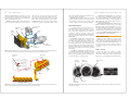
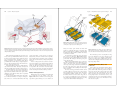
Figure 38-15. Most hybrid power control modules have two
orange cables that connect to the battery pack and three large
orange cables that connect to the motor-generator. (Honda)
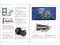
Motor-generator 3
Motor-generator 2
Figure 38-13. This all-wheel drive hybrid drive train uses two motor-generators in the transaxle and a third motor-generator in the
rear drive axle assembly.
Motor-generator 2
Motor-generator 1
Stator
Motor-generator 3
Stator
Rotor
The converter circuit in the power control module
can step dc voltage up or down. It does not change ac to
dc or dc to ac. Hybrid battery pack voltage must usually
be stepped up to efficiently drive the inverter circuit and
the motor-generator. Battery pack voltage must be
stepped down to charge the vehicle’s 12-volt battery.
An inverter circuit in the hybrid power control
module changes dc to ac and ac to dc. When high-voltage
dc is fed into the inverter circuit from the battery pack for
electric propulsion, the inverter circuit changes it to highvoltage 3-phase ac to run the motor-generator. When
3-phase ac is fed into the inverter circuit from the motorgenerator, the ac is changed back into high-voltage dc for
recharging the battery pack.
The motor-generator ECU controls the inverter and
converter circuits to efficiently operate the motor-generator(s). The motor-generator ECU responds to control
signals from the hybrid ECU and transaxle ECU.
Rotor
Battery Relays and Contactors
Front Transaxle
Rear Transaxle
(with 4WD System)
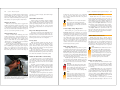
Figure 38-14. Compare the construction of a front hybrid transaxle to that of a rear hybrid transaxle. (Toyota)
Battery relays and contactors are used to control the
flow of electricity between the battery pack and the
power control module. As shown in Figure 38-16, when
the ignition key is off and battery relays are open, the
large high-current contactors are also open and no battery
voltage can flow to the power control module and motorgenerator.
However, when the ignition key is turned to run, the
ECU energizes the battery relays. The relays close and
send current to the large contactor coils, which pull the
contactor lugs closed. High voltage and high current can
then flow through the contactor lugs to the power control
module.
705
Hybrid Drive ECU
The hybrid drive ECU controls the power control
module and motor-generator to keep the HV battery pack
operating at the optimum temperature and state of charge.
It helps utilize battery power efficiently and properly
recharge the HV battery pack when partially drained by
activating the regenerative braking system. By keeping
the HV battery pack at optimum charge and temperature,
the hybrid drive ECU increases battery service life and
fuel economy.
When the accelerator of a hybrid is depressed, a
pedal position sensor sends a signal to the hybrid drive
ECU. The hybrid ECU determines whether to drive in the
all-electric mode (slow acceleration), start the gas engine
(rapid acceleration), or use a combination of gas engine
and electric drive based on information in its memory.
Power Splitter
A hybrid power splitter is a planetary gearset used to
control the transfer of power through the hybrid drive
train. The hybrid power splitter and transaxle are under
computer control.
When the driver moves the gearshift selector in the
passenger compartment, an electric signal is sent from
the shift lever position sensor to the hybrid ECU. The
hybrid ECU then energizes or shuts off specific solenoids
in the transaxle. The solenoids can apply or release friction bands or clutches to hold or release members of the
power splitter. By holding or releasing different parts of
the power splitter, the solenoids control the planetary
gearset(s) and the flow of torque from both the internal
combustion engine and the electric drive system. When a
motor-generator is operating as a generator, the splitter
can transfer driveline torque into the motor-generator
armature during braking or coasting.
As shown in Figure 38-17, the engine crankshaft is
connected to a shaft running through the front motor-generator and into the planetary gearset. The planet carrier is
splined to the engine crankshaft. The planet ring gear is
connected to the front motor-generator armature. The
rear motor-generator is connected to the front motor-generator and to a reduction gear mechanism.
Hybrid Power Cables
Hybrid power cables transfer extremely high-voltages to the components of the electric drive system. The
power cables are heavily insulated to prevent these voltages from shorting to ground.
Two large power cables connect the battery pack to
the power control module. Three large power cables