1
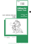
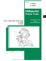
MODELS
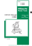
C 12LSH
C 12RSH
Hitachi
Power Tools
C
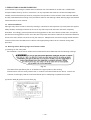
SLIDE COMPOUND MITER SAW
C 12LSH
C 12RSH
LIST Nos. C 12LSH: E941
C 12RSH: E942
TECHNICAL DATA
AND
SERVICE MANUAL
May 2005
SPECIFICATIONS AND PARTS ARE SUBJECT TO CHANGE FOR IMPROVEMENT
REMARK:
Throughout this TECHNICAL DATA AND SERVICE MANUAL, a symbol(s)
is(are) used in the place of company name(s) and model name(s) of our
competitor(s). The symbol(s) utilized here is(are) as follows:
Competitors
Symbols Utilized
Company Name
Model Name
C
MAKITA
LS1212
P
DEWALT
DW708
CONTENTS
Page
1. PRODUCT NAME ............................................................................................................................ 1
2. MARKETING OBJECTIVE .............................................................................................................. 1
3. APPLICATIONS ............................................................................................................................... 1
4. SELLING POINTS ........................................................................................................................... 2
4-1. Selling Point Descriptions ................................................................................................................ 3
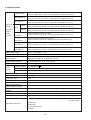
5. SPECIFICATIONS ......................................................................................................................... 12
6. COMPARISONS WITH SIMILAR PRODUCTS ............................................................................. 14
7. PRECAUTIONS IN SALES PROMOTION .................................................................................... 16
7-1. Instruction Manual .......................................................................................................................... 16
7-2. Warning Labels, Warning Signs and Caution Labels ......................................................................16
7-3. Relative Standards ......................................................................................................................... 18
7-4. Laser Marker ..................................................................................................................................18
7-5. Ambient Illuminance and Visibility of Laser Line .............................................................................19
7-6. Precautions Concerning Brake (For USA/CAN) ............................................................................ 19
8. ADJUSTMENT AND OPERATIONAL PRECAUTIONS ................................................................ 20
8-1. Confirmation of Saw Blade Lower Limit Position ............................................................................20
8-2. Confirmation for Use of Sub Fence (A) and Sub Fence (B) ........................................................... 21
8-3. Position Adjustment of Laser Line .................................................................................................. 22
8-4. How to Use the Vise Assembly .......................................................................................................23
8-5. Adjustment of Table Insert Position .................................................................................................24
8-6. Cutting Operation ............................................................................................................................ 25
8-7. Digital Display Panel (Only Model C 12LSH) .................................................................................. 32
8-8. Precautions Concerning Electronic Condition ................................................................................ 33
9. ADJUSTMENT OF COMPONENTS .............................................................................................. 34
9-1. Bevel Angle Adjustment .................................................................................................................. 34
9-2. Ball Bushing (Linear Bearing) ......................................................................................................... 34
10. PACKING ..................................................................................................................................... 35
11. PRECAUTIONS IN DISASSEMBLY AND REASSEMBLY .......................................................... 37
11-1. Precautions in Disassembly and Reassembly of the Laser Marker .............................................. 37
11-2. Disassembly ..................................................................................................................................37
11-3. Reassembly ..................................................................................................................................51
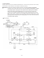
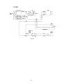
11-4. Wiring Diagram ............................................................................................................................. 52
11-5. Checking of Insulation Distance .................................................................................................... 56
Page
11-6. No-load Current .............................................................................................................................. 56
11-7. Reassembly Requiring Adjustment ................................................................................................ 56
11-8. Lubrication ...................................................................................................................................... 57
11-9. Product Precision ........................................................................................................................... 57
11-10. Adjustment of Laser Marker Accuracy..........................................................................................58
12. REPAIR GUIDE ............................................................................................................................ 61
13. STANDARD REPAIR TIME (UNIT) SCHEDULES ....................................................................... 67
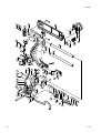
Assembly Diagram for C 12LSH
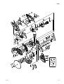
Assembly Diagram for C 12RSH
1. PRODUCT NAME
Hitachi Slide Compound Miter Saws, Models C 12LSH/C 12RSH
2. MARKETING OBJECTIVE
The new slide compound miter saws Models C 12LSH and C 12RSH are introduced. They are compact thanks to
the new sliding system that allows only the head portion to slide from the front to the back. They are equipped
with the laser marker and the digital display panel that indicates miter/bevel angles (Model C 12LSH only) for
increased visibility. In addition, they incorporate many features such as the turn table and the miter/bevel angle
fine adjustment function. The new Models C 12LSH and C 12RSH are more convenient than the conventional
ones.
3. APPLICATIONS
Cutting various types of wood workpieces
Cutting workpieces of plywood, decoration panels, soft fiberboards and hard boards
Cutting aluminum sashes
--- 1 ---
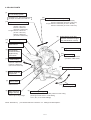
4. SELLING POINTS
(1) Compact body thanks to
the new sliding system
Operable even in tight places because
the depth of the main unit is 930 mm.
(14)
Compound (miter + bevel) cutting
To left:
H70 mm x W220 mm (H2-3/4" x W8-5/8")
H75 mm x W180 mm (H2-15/16" x W7-1/16")
To right: H45 mm x W220 mm (H1-3/4" x W8-5/8")
H50 mm x W180 mm (H1-15/16" x W7-1/16")
(13) Right and left bevel cutting
To left:
H70 mm x W312 mm
(H2-3/4" x W12-1/4")
H75 mm x W260 mm
(H2-15/16" x W10-3/16")
To right: H45 mm x W312 mm
(H1-3/4" x W12-1/4")
H50 mm x W260 mm
(H1-15/16" x W10-3/16")
(2) Digital display panel that
indicates miter/bevel angles
(Only the Model C 12LSH)
(15) Powerful 15 amps motor
(8) High dust collecting
performance
(6) Aggressive tool design
(7) Conveniently
positioned bevel
angle locking
mechanism
(10)
(11)
Slide cutting
H107 mm x W312 mm
(H4-3/16" X W12-1/4")
H120 mm x W260 mm
(H4-11/16" X W10-3/16")
(4)
(3)
Press cutting
H107 mm x W107 mm
(H4-3/16" x W4-3/16")
(4) Miter angle fine adjustment
Bevel angle fine
adjustment
Laser marker
For easier alignment
with the ink line
(12)
Miter cutting
[ Left 45˚, right 57˚]
(5)
(9)
High sub fence
(Right and left)
120 mm (4-11/16") in height
NOTE: Numerals in (
Positive angle stoppers
For easy adjustment of the turn table position for miter cutting
(At the right and left of the 0˚ center setting,
at 15˚, 22.5˚, 31.6˚ and 45˚settings)
) are identical with item numbers in "4-1. Selling Point Descriptions".
--- 2 ---
4-1. Selling Point Descriptions
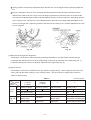
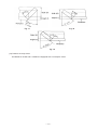
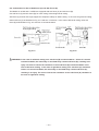
(1) Compact body thanks to the new sliding system
1
Operable even in tight places
When moving the motor head, the slide pipe also moves together extending backward in the case of the
conventional slide compound miter saws. The Models C 12LSH and C 12RSH are equipped with the new
system that allows only the motor head to slide from the front to the back. As shown in Fig. 1, the slide pipe
does not extend backward when sliding the motor head from the front to the back. Therefore, the depth of the
main unit remains unchanged (930 mm). The Models C 12LSH and C 12RSH are operable even in tight
places such as a place where there is a wall behind.
When the motor head
is at the front position
When the motor head
is at the back position
The slide pipe does
not extend backward.
Depth
Depth
Fig. 1
Table 1
Unit: mm (inch)
Dimension of the main unit (Width x Depth x Height)
Model
When the motor head is at the front position When the motor head is at the back position
HITACHI
C 12LSH/C 12RSH
595 x 930 x 710
(23-7/16" x 36-5/8" x 27-15/16")
595 x 930 x 710
(23-7/16" x 36-5/8" x 27-15/16")
HITACHI
C 12FSA
580 x 1,120 x 675
(22-7/8" x 44-3/32" x 29-9/16")
580 x 1,120 x 675
(22-7/8" x 44-3/32" x 29-9/16")
C
590 x 800 x 690
(23-1/4" x 31-1/2" x 27-1/4")
590 x 1,035 x 690
(23-1/4" x 40-3/4" x 27-1/4")
P
595 x 910 x 660
(23-7/16" x 35-13/16" x 26")
595 x 1,120 x 660
(23-7/16" x 44-3/32" x 26")
--- 3 ---
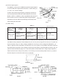
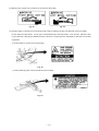
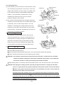
2
Adjustable sliding amount
The sliding amount of the motor head is adjustable by loosening the slide lock knob at holder (A) side and
changing the slide pipe position (Fig. 2-a). It is convenient for making continuous grooves halfway through the
sliding operation (Fig. 2-b).
Slide lock knob
(Be sure to lock the knob after adjustment.)
Holder (A)
Slide
Adjust
Workpiece
Slide pipe
Fig. 2-a
Fig. 2-b
(2) Digital display panel that indicates miter/bevel angles
(Only the Model C 12LSH)
Use the digital display panel when cutting a workpiece at
an optional angle. The digital display panel indicates a
miter/bevel cutting angle with a numeric value. There is
no reading error caused by visual check between the
indicator and the scale. The digital display indicates a
miter angle or a bevel angle in increments of 0.5˚. The
Fig. 3
digital display is equipped with the convenient back light
ON/OFF switch that makes the display easily readable
even in a dimly lit place (Fig. 3).
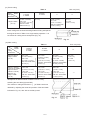
(3) Laser marker
Use the laser marker for aligning with the ink line on the
workpiece.
Cutting position can be properly adjusted by aligning the
positioning ink line with the laser line. There is no need to
make a long ink line on the workpiece.
2
There is no need to lower the motor head to align with the
Laser
marker
ink line because the laser marker makes a laser line on the
workpiece. In addition, cutting position can be easily
adjusted because the operator can hold the workpiece with
both hands to move.
--- 4 ---
Fig. 4-a
3
Cutting position can be easily adjusted because the laser line can be aligned with an optionally angled ink
line.
4
Even the workpieces such as crown moldings and base boards that have decorative surfaces and are
difficult to be made an ink line can be cut just by aligning the laser line with the ink line on the fence side.
The laser line is adjusted to the width of the saw blade at the time of factory shipment. Depending upon the
user's cutting choice, the laser line can be aligned with the left side of the cutting width (saw blade) or the
ink line on the right side. Adjust the position of the laser line according to "8-4. Position Adjustment of Laser
Line" on page 23.
Fig. 4-b
Fig. 4-c
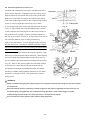
(4) Miter and bevel angle fine adjustment
The Model C 12LSH and C 12RSH are easily and finely adjustable to an optional miter and bevel angle.
Loosen the side handle and turn knob (A) while pulling up the lever to adjust the miter angle finely (Fig. 7).
Loosen the clamp lever and turn knob (B) to adjust the bevel angle finely (Fig. 6).
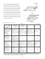
(5) High sub fence
The Models C 12LSH and C 12RSH have a high sub fence (right and left). Use the high sub fence for miter
cutting, left and right bevel cutting or crown molding cutting. The high sub fence supports the workpiece
widely for stable cutting.
Table 2
Height
of fence
Maker
Model
Fixation
fence
High sub
fence
HITACHI
C 12LSH
C 12RSH
HITACHI
C 12FSA
Unit: mm (inch)
P
C
A
Left 50 (1-15/16")
Left 49 (1-15/16")
Left 45 (1-3/4")
Left 29 (1-1/8")
B
Left
Left
Left 80 (3-3/16")
Left
C
Left 120 (4-11/16")
Left 70 (2-3/4")
Left 115 (4-1/2")
Left
E
Right 45 (1-3/4")
Left 120 (4-11/16")
(Rotary type)
Right 120 (4-11/16")
(Rotary type)
Right 30.5 (1-3/16") Right 30 (1-3/16")
Left 115 (4-1/2")
Left none
(Rotary type)
D
F
Right none
--- 5 ---
Right none
Right 29 (1-1/8")
Left 109 (4-5/16")
(Horizontally movable type)
Right 109 (4-5/16")
(Horizontally movable type)
Left
Fixation fence
Right
High sub fence
High sub fence
Fixation fence
C
F
D
A
B
E
Fig. 5-a
Fig. 5-b
(6) Aggressive tool design
The tool color is gunmetallic silver to give a sturdier image. The circular
saw portion is of a powerful, original and aggressive design.
(7) Conveniently positioned bevel angle locking mechanism
In the case of the conventional slide compound miter saws, the
clamp lever is positioned at the rear of the main unit. The Models
C 12LSH and C 12RSH are equipped with the clamp lever
conveniently positioned at the upper position for easier bevel angle
Fig. 6
locking.
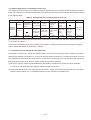
(8) High dust collecting performance
The dust collecting performance of the Models C 12LSH and C 12RSH are remarkably higher than the other
models thanks to the adoption of new dust guide and gear case.
Table 3
Maker
Model
(%)
HITACHI
C 12LSH
C 12RSH
C
P
Press cutting *1
(Size of the workpiece:
105 mm x 105 mm
(4-1/8" x 4-1/8"))
66.6
40.2
8
Slide cutting *2
(Size of the workpiece:
105 mm x 105 mm
(4-1/8" x 4-1/8"))
91.2
84.8
11.0
Cutting
method
*1: This is a method to cut a workpiece by shaking the motor head.
*2: This is a method to cut a workpiece by sliding the motor head from the front.
The dust collecting performance may vary depending on the workpiece and operating conditions.
The dust collecting performance is obtained from the following formula:
Dust collecting performance (%) =
Weight of sawdust accumulated in the dust bag (g)
Weight of all sawdust during cutting (g)
--- 6 ---
x 100
(9) Positive angle stoppers
The Models C 12LSH and C 12RSH have positive angle stoppers
in the turn table at the right and the left of the 0˚ center setting, at
15˚, 22.5˚, 31.6˚ and 45˚ settings.
Thanks to the positive angle stoppers, positioning can be done
more securely than the ball index method utilized in the current
Model C 12FSA. In addition, a lever is provided at the lower tip of
the turn table to secure or release the positive angle stoppers.
Adjustment of the turn table and positioning can be easily done
while holding the side handle.
Fig. 7
(10) Slide cutting
Table 4
Maker
Model
Max.
cutting
dimensions
Height x Width
(H x W)
Unit: mm (inch)
HITACHI
C 12LSH
C 12RSH
HITACHI
C 12FSA
C
107 x 312
(4-3/16" x 12-1/4")
120 x 260
(4-11/16" x 10-3/16")
with aux. board width
25 mm (1")
107 x 305
(4-3/16" x 12")
120 x 260
(4-11/16" x 10-3/16")
with aux. board width
20 mm (13/16")
98 x 310
(3-7/8" x 12-1/4")
120 x 230
(4-11/16"x 9")
with aux. board width
34 mm (1-5/16")
P
102 x 305
(4" x 12")
115 x 299
(4-1/2" x 11-3/4")
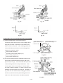
Workpieces as wide as shown in Table 4 can be cut with the motor head sliding. The lower limit position of the
saw blade is factory-adjusted so that workpieces up to 107 mm (4-3/16") high and 312 mm (12-1/4") wide can
be cut as shown in Fig. 9-a. When cutting a workpiece of 120 mm (4-11/16") in height as indicated in [ ] in
Table 4, adjust the saw so that there is a clearance of 2 to 3 mm (3/32" to 1/8") between the bottom surface of
the head and the top surface of the workpiece at the lower limit position of the saw blade as shown in Fig. 9-b.
(See the Instruction Manual, page 18 "4. Lower limit position of saw blade when cutting a large workpiece".)
Please note that when cutting in this position, it is necessary to use an auxiliary board of 25 mm (1") wide so
that the workpiece on the fence side can be cut full width.
Fig. 8
Fig. 9-a
Fig. 9-b
--- 7 ---
(11) Press cutting
Table 5
Maker
Max.
Model
cutting
dimensions
HITACHI
C 12LSH
C 12RSH
Height x Width
107 x 107
(4-3/16" x 4-3/16")
120 x 120
(4-11/16" x 4-11/16")
with aux. board
width 25 mm (1")
(H x W)
Unit: mm (inch)
HITACHI
C 12FSA
P
C
98 x 134
(3-7/8" x 5-1/4")
107 x 122
(4-1/4" x 4-13/16")
100 x 100
(4" x 4")
102 x 102
(4" x 4")
115 x 115
(4-1/2" x 4-1/2")
[with aux. board width
34 mm (1-5/16")]
Press cutting with the head swiveling enables cutting workpieces
as large as shown in Table 5 in a single sawing operation. It is
convenient for cutting narrow workpieces (Fig. 10).
Fig. 10
(12) Miter cutting
Table 6
Maker
Model
Max.
cutting
dimensions
HITACHI
C 12LSH
C 12RSH
Unit: mm (inch)
HITACHI
C 12FSA
C
Right and left 45˚
Height x Width
(H x W)
107 x 220
(4-3/16" x 8-5/8")
120 x 180
(4-11/16" x 7-1/16")
with aux. board width
25 mm (1")
107 x 220
(4-3/16" x 8-5/8")
120 x 180
(4-11/16" x 7-1/16")
with aux. board width
25 mm (1")
98 x 220
(3-7/8" x 8-5/8")
120 x 162
(4-11/16" x 6-3/8")
[with aux. board width
24 mm (15/16")]
Right 57˚ (Hitachi
C 12LSH, C 12RSH)
Right and left 57˚
(Hitachi C 12FSA)
107 x 170
(4-3/16" x 6-11/16")
120 x 130
(4-11/16" x 5-1/8")
with aux. board width
25 mm (1")
107 x 180
(4-3/16" x 7-1/16")
120 x 140
(4-11/16" x 5-1/2")
with aux. board width
25 mm (1")
98 x 155
(3-7/8" x 6-1/8")
120 x 115
(4-11/16" x 4-1/2")
with aux. board width
17 mm (11/16")
Right 60˚ (C)
Height x Width
(H x W)
Workpieces as wide as shown in Table 6 can be cut by
swiveling the turn table (right and left).
The maximum cutting dimensions in [
] in Table 6 are those
obtained by adjusting the lower limit position of the saw blade
indicated in Fig. 9-b, also with an auxiliary board.
Fig. 11
--- 8 ---
P
102 x 216
(4" x 8-1/2")
115 x 203
(4-1/2" x 8")
(13) Right and left bevel cutting
1
Maximum cutting dimension
Table 7
Maker
Model
Max.
cutting
dimensions
HITACHI
C 12LSH
C 12RSH
HITACHI
C 12FSA
Unit: mm (inch)
P
C
Left 45˚
Height x Width
(H x W)
70 x 312
(2-3/4" x 12-1/4")
75 x 260
(2-15/16" x 10-3/16")
with aux. board width
25 mm (1")
70 x 305
(2-3/4" x 12")
75 x 260
(2-15/16" x 10-3/16")
with aux. board width
20 mm (13/16")
55 x 310
(2-3/16" x 12-1/4")
69 x 230
(2-3/4" x 9")
[with aux. board
34 mm (1-5/16")]
57 x 305
(2-1/4" x 12")
79 x 200
(3-1/8" x 7-7/8")
Right 45˚
Height x Width
(H x W)
45 x 312
(1-3/4" x 12-1/4")
50 x 260
(1-15/16" x 10-3/16")
with aux. board width
25 mm (1")
40 x 305
(1-9/16" x 12")
45 x 260
(1-3/4" x 10-3/16")
with aux. board width
20 mm (13/16")
35 x 310
(1-3/8" x 12-1/4")
49 x 230
(1-15/16" x 9")
[with aux. board width
34 mm (1-5/16")]
28 x 305
(1-1/8" x 12")
41 x 270
(1-5/8" x 10-5/8")
Workpieces as wide as shown in Table 7 can be bevel-cut by tilting the saw blade (right and left).
Fig. 12
2
Fig. 13
Bevel cutting
Fig. 15
Fig. 14
--- 9 ---
Figures 14 and 15 show the right and left bevel
cutting by the Models C 12LSH and C 12RSH.
More accurate miter cutting is performed because
the same reference plane (surface of the workpiece
which contacts the fence) is used in both the left
bevel cutting and the right bevel cutting (Fig. 13).
Even an oddly shaped workpiece can be accurately
bevel-cut in either left or right by making the wide
and stable surface of the workpiece as the reference
plane as shown in Fig. 16. In addition, the working
efficiency is improved because there is no need to
turn around the workpiece.
Fig. 16
(14) Compound (miter + bevel) cutting
Table 8
Maker
Model
Max. cutting
dimensions
Left miter 45˚
(Hitachi C 12FSA Right
and left miter 45˚)
((C) Right and left
miter 45˚)
Left bevel 45˚
Height x Width
(H x W)
Right miter 31˚
Left bevel 45˚
Height x Width
(H x W)
Right miter 45˚
((C) Right and left
miter 45˚)
Right bevel 45˚
Height x Width
(H x W)
Left miter 31˚
Right bevel 45˚
Height x Width
(H x W)
Unit: mm (inch)
HITACHI
C 12LSH
C 12RSH
HITACHI
C 12FSA
C
70 x 220
(2-3/4" x 8-5/8")
75 x 180
(2-15/16" x 7-1/16")
with aux. board width
25 mm (1")
70 x 220
(2-3/4" x 8-5/8")
75 x 180
(2-15/16" x 7-1/16")
with aux. board width
25 mm (1")
55 x 220
(2-3/16" x 8-5/8")
69 x 162
(2-3/4" x 6-3/8")
with aux. board width
24 mm (15/16")
45 x 220
(1-3/4" x 8-5/8")
50 x 180
(1-15/16" x 7-1/16")
with aux. board width
25 mm (1")
40 x 220
(1-9/16" x 8-5/8")
45 x 180
(1-3/4" x 7-1/16")
with aux. board width
25 mm (1")
35 x 220
(1-3/8" x 8-5/8")
49 x 162
(1-15/16" x 6-3/8")
with aux. board width
24 mm (15/16")
45 x 265
(1-3/4" x 10-7/16")
50 x 220
(1-15/16" x 8-5/8")
with aux. board width
25 mm (1")
40 x 265
(1-9/16" x 10-7/16")
45 x 220
(1-3/4" x 8-5/8")
with aux. board width
20 mm (13/16")
P
57 x 216
(2-1/4" x 8-1/2")
79 x 203
(3-1/8" x 8")
70 x 265
(2-3/4" x 10-7/16")
75 x 220
(2-15/16" x 8-5/8")
with aux. board width
25 mm (1")
28 x 216
(1-1/8" x 8-1/2")
41 x 203
(1-5/8" x 8")
By turning the turn table to the left or right and inclining the saw blade section (head) to the left or right, the
Models C 12LSH and C 12RSH are capable of compound cutting (bevel + miter, see Figs. 17, 18 and 19) of
workpieces with the maximum dimensions shown in Table 8.
--- 10 ---
(Le
ft)
Fig. 18
Fig. 17
Fig. 19
(15) Powerful 15 amps motor
The Models C 12LSH and C 12RSH are equipped with a 15-ampere motor.
--- 11 ---
5. SPECIFICATIONS
0˚ (Right angle)
107 mm x 312 mm (4-3/16" x 12-1/4")
120 mm x 260 mm (4-11/16" x 10-3/16") [with aux. board 25 mm (1")]
Miter left/right 45˚
107 mm x 220 mm (4-3/16" x 8-5/8")
120 mm x 180 mm (4-11/16" x 7-1/16") [with aux. board 25 mm (1")]
Miter right 57˚
107 mm x 170 mm (4-3/16" x 6-11/16")
120 mm x 130 mm (4-11/16" x 5-1/8") [with aux. board 25 mm (1")]
Maximum
Left 45˚
cutting
Bevel
dimentions
Right 45˚
Height x
Miter left 45˚
Width
+
Bevel left 45˚
(H x W)
Miter right 31˚
+
Bevel left 45˚
Miter right 45˚
+
Bevel right 45˚
Miter left 31˚
+
Bevel right 45˚
70 mm x 312 mm (2-3/4" x 12-1/4")
75 mm x 260 mm (2-15/16" x 10-3/16") [with aux. board 25 mm (1"))
45 mm x 312 mm (1-3/4" x 12-1/4")
50 mm x 260 mm (1-15/16" x 10-3/16") [with aux. board 25 mm (1"))
70 mm x 220 mm (2-3/4" x 8-5/8")
75 mm x 180 mm (2-15/16" x 7-1/16") [with aux. board 25 mm (1"))
70 mm x 265 mm (2-3/4" x 10-7/16")
75 mm x 220 mm (2-15/16" x 8-5/8") [with aux. board 25 mm (1"))
45 mm x 220 mm (1-3/4" x 8-5/8")
50 mm x 180 mm (1-15/16" x 7-1/16") [with aux. board 25 mm (1"))
45 mm x 265 mm (1-3/4" x 10-7/16")
50 mm x 220 mm (1-15/16" x 8-5/8") [with aux. board 25 mm (1"))
Miter cutting ranges
Left 0˚ --- 46˚, Right 0˚ --- 57˚
Bevel cutting ranges
Right and left 0˚ --- 45˚
Compound (miter + bevel)
cutting ranges
Miter left 45˚ to right 31˚ + left bevel 0˚ to 45˚
Miter left 31˚ to right 45˚ + right bevel 0˚ to 45˚
Angle stopper positions
0˚, right and left 15˚, 22.5˚, 31.6˚ and 45˚
Applicable saw blade
305 mm (12") external dia. x 25.4 mm (1") bore
Laser
marker
Maximum output
< 1 mW (CLASS )
Wave length
400 nm to 700 nm
Laser medium
Laser diode
Power source type and voltage AC single phase 60 Hz, 120 V
Type of motor
AC single phase commutator series motor
Full-load current
15 A
No-load rotation speed
3,800 min-1
Max. output
Main body dimensions
(Width x Depth x Height)
Approx. 1,850 W
Weight
C 12LSH 30 kg (66.1 lbs.) C 12RSH 29 kg (63.9 lbs.)
Coating
Gunmetallic silver
Packaging
Corrugated cardboard box
Cord
Type: 2-conductor cabtire cable Length: 1.8 m (6 ft)
Standard accessories
595 mm x 930 mm x 710 mm (23-7/16" x 36-5/8" x 27-15/16")
305 mm (12") TCT saw blade (25.4 mm (1") bore), NT60, Code No. 726100)
......................... for wood cutting
Dust bag
Vise ass'y
17 mm box wrench
Holder
--- 12 ---
Optional accessories
Extension holder and stopper (Code No. 324369)
Crown molding vise ass'y (Code No. 321434)
(Including crown molding stopper (L))
Crown molding stopper (L) (Code No. 321374)
Crown molding stopper (R) (Code No. 321373)
--- 13 ---
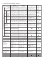
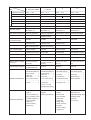
6. COMPARISONS WITH SIMILAR PRODUCTS
Maker
Model
Item
Max. cutting dimensions Height x Width mm (inch)
C
P
98 x 310 (3-7/8" x 12-1/14")
107 x 312 (4-3/16" x 12-1/4") 107 x 305 (4-3/16" x 12")
120 x 260 (4-11/16" x 10-3/16") 120 x 260 (4-11/16" x 10-3/6") 120 x 230 (4-11/16" x 9")
[with aux. board 25 mm (1")] [with aux. board 20 mm (13/16")] [with aux. board 34 mm (1-5/16")]
102 x 305
(4" x 12")
115 x 299
(4-1/2" x 11-3/4")
Left/right
45˚
98 x 220 (3-7/8" x 8-5/8")
107 x 220 (4-3/16" x 8-5/8")
107 x 220 (4-3/16" x 8-5/8")
120 x 180 (4-11/16" x 7-1/16") 120 x 180 (4-11/16" x 7-1/16") 120 x 162 (4-11/16" x 6-3/8")
[with aux. board 25 mm (1")] [with aux. board 25 mm (1")] [with aux. board 24 mm (15/16")]
102 x 216
(4" x 8-1/2")
115 x 203
(4-1/2" x 8")
Right 57˚
(C 12FSA
R/L 57˚ )
(C: R60)
107 x 170 (4-3/16" x 6-11/16") 107 x 180 (4-3/16" x 7-1/16") 98 x 155 (3-7/8" x 6-1/8")
120 x 130 (4-11/16" x 5-1/8") 120 x 140 (4-11/16" x 5-1/2") 120 x 115 (4-11/16" x 4-1/2")
[with aux. board 25 mm (1")] [with aux. board 25 mm (1")] [with aux. board 17 mm (11/16")]
Left 45˚
55 x 310 (2-3/16" x 12-1/4")
70 x 305 (2-3/4" x 12")
70 x 312 (2-3/4" x 12-1/4")
75 x 260 (2-15/16" x 10-3/16") 75 x 260 (2-15/16" x 10-3/16") 69 x 230 (2-3/4" x 9")
[with aux. board 25 mm (1")] [with aux. board 20 mm (13/16")] [with aux. board 34 mm (1-5/16")]
57 x 305
(2-1/4" x 12")
79 x 200
(3-1/8" x 7-7/8")
Right 45˚
35 x 310 (1-3/8" x 12-1/4")
40 x 305 (1-9/16" x 12")
45 x 312 (1-3/4" x 12-1/4")
49 x 230 (1-15/16" x 9")
50 x 260 (1-15/16" x 10-3/16") 45 x 260 (1-3/4" x 10-3/16")
[with aux. board 25 mm (1")] [with aux. board 20 mm (13/16")] [with aux. board 34 mm (1-5/16")]
28 x 305
(1-1/8" x 12")
41 x 270
(1-5/8" x 10-5/8")
0˚ (Right angle)
Miter
HITACHI
C 12FSA
HITACHI
C 12LSH/C 12RSH
Bevel
Miter left 45˚
55 x 220 (2-3/16" x 8-5/8")
70 x 220 (2-3/4" x 8-5/8")
(C 12FSA R/L 45˚) 70 x 220 (2-3/4" x 8-5/8")
69 x 162 (2-3/4" x 6-3/8")
75
x
180
(2-15/16"
x
7-1/16")
((C) R/L 45˚)
75 x 180 (2-15/16" x 7-1/16")
+
[with aux. board 24 mm (15/16")]
[with
aux.
board
25
mm
(1")]
[with aux. board 25 mm (1")]
Bevel left 45˚
Miter right 31˚
+
Bevel left 45˚
Miter right 45˚
((C) R/L 45˚)
+
Bevel right 45˚
Miter left 31˚
+
Bevel right 45˚
57 x 216
(2-1/4" x 8-1/2")
79 x 203
(3-1/8" x 8")
70 x 265 (2-3/4" x 10-7/16")
75 x 220 (2-15/16" x 8-5/8")
[with aux. board 25 mm (1")]
35 x 220 (1-3/8" x 8-5/8")
40 x 220 (1-9/16" x 8-5/8")
45 x 220 (1-3/4" x 8-5/8")
49 x 162 (1-15/16" x 6-3/8")
50 x 180 (1-15/16" x 7-1/16") 45 x 180 (1-3/4" x 7-1/16")
[with aux. board 25 mm (1")] [with aux. board 25 mm (1")] [with aux. board 24 mm (15/16")]
28 x 216
(1-1/8" x 8-1/2")
41 x 203
(1-5/8" x 8")
45 x 265 (1-3/4" x 10-7/16") 40 x 265 (1-9/16" x 10-7/16")
50 x 220 (1-15/16" x 8-5/8") 45 x 220 (1-3/4" x 8-5/8")
[with aux. board 25 mm (1")] [with aux. board 20 mm (13/16")]
Groove cutting width
Possible
Possible
Possible
Possible
(with screw height
(with bolt height adjustment) (with bolt height adjustment) (with bolt height adjustment) adjustment)
Miter cutting ranges
Left 0˚ --- 46˚, right
Bevel cutting ranges
Left and right
Compound
(miter + bevel)
cutting ranges
Angle stopper positions
0˚ --- 57˚ Left 0˚ --- 57˚, right
0˚ --- 45˚
Miter left 0˚ --- 45˚/
Miter right 0˚ --- 31˚
Left and right
0˚ --- 57˚ Left 0˚ --- 47˚, right
0˚ --- 45˚
Left and right
0˚ --- 60˚ Left 0˚ --- 50˚,
0˚ --- 45˚
Miter left and right 0˚ --- 45˚
Bevel left 0˚ --- 45˚
Miter left and right 0˚ --- 45˚
Bevel left and right 0˚ --- 45˚
Miter left 0˚ --- 31˚/
Miter left 0˚ --- 31˚/
Miter right 0˚ --- 45˚
Bevel right 0˚ --- 45˚
Miter right 0˚ --- 45˚
Bevel right 0˚ --- 45˚
Miter right 0˚ --- 60˚/
Bevel left 0˚ --- 35˚
Bevel right 0˚ --- 45˚
Bevel left 0˚ --- 45˚
right 0˚ --- 60˚
Left and right
0˚ --- 48˚
Miter left and right
0˚ --- 45˚
Bevel left and
right 0˚ --- 45˚
0˚, right and left 15˚, 22.5˚, 0˚, right and left 15˚, 22.5˚, 0˚, right and left 15˚, 22.5˚, 0˚, right 15˚, 22.5˚,
30˚, 45˚
31.6˚, 35.3˚, 45˚
31.6˚, 45˚
31.6˚, 45˚, 60˚
0˚, left 15˚, 22.5˚,
31.6˚, 45˚, 50˚
Saw blade external
diameter mm (inch)
(No. of teeth)
305 (12") (60 P)
305 (12") (60 P)
305 (12") (70 P)
305 (12") (60 P)
Laser marker
Provided
Not provided
Not provided
Not provided
Laser output
<1 mW
Digital display
Provided (C 12LSH only)
None
None
None
--- 14 ---
Maker/Model
Item
Full-load current (A)
HITACHI
C 12LSH/C 12RSH
120 V --- 15 A
Motor
No-load revolution (min-1) 3,800
HITACHI
C 12FSA
C
P
120 V --- 12 A
120 V --- 15 A
120 V --- 15 A
3,200
3,200
4,000
Max. output (W)
Approx. 2,100
Approx. 1,940
Soft-start
Not provided
Provided (electric control) Provided (electric control) Not provided
Speed control
Not provided
Provided (electric control) Provided (electric control) Not provided
Poly V belt overload protector Not provided
Approx. 2,100
Provided (electric control) Not provided
Not provided
Saw blade drive system
Poly V belt + Gear
Poly V belt + Gear
Gear
Poly V belt + Gear
Slide drive system
On top of workpiece
Slide pipes x 2
On top of workpiece
Slide pipes x 2
Under workpiece
Slide pipes x 2
On top of workpiece
Slide pipes x 2
Slide clearance adjustment Externally adjustable
Externally adjustable
Disassembly is required Externally adjustable
Insulation structure
Double insulation
Double insulation
Double insulation
Double insulation
Height adjustment
of workpiece holder
Possible
Possible
Possible
Impossible
Miter scale
With angle and
inclination scale
With angle and
inclination scale
With angle and
inclination scale
With angle scale
Splinter guard
Provided
(with ink line alignment)
Provided
(with ink line alignment)
Not provided
Not provided
Type of angle stopper
Positive stopper
Ball index
Positive stopper
Detent plate
High fence (sub fence)
Provided (left and right) Not provided
Provided (left)
Provided (left and right)
Capacity of dust bag (l)
3
2
3
2
Power cord accommodation External
External
External
External
Main unit dimensions
[Width x Depth x Height]
mm (inch)
595 x 930 x 710
(23-7/16" x 36-5/8" x
27-15/16")
580 x 1,120 x 675
(22-7/8" x 44-3/32" x
29-9/16")
590 x 800 x 690
(23-1/4" x 31-1/2" x
27-1/4")
595 x 910 x 660
(23-7/16" x 35-13/16" x
26")
Product weight kg (lbs.)
C 12LSH 30 (66.1)
C 12RSH 29 (63.9)
25 (55.1)
22 (48.4)
25.8 (57)
• 305 mm (12") TCT
saw blade (NT60) for
wood cutting ......... 1
• Dust bag .............. 1
• Vise ass'y ............. 1
• 17 mm box wrench
............................... 1
• Holder (B) ............ 1
• 10 mm x 13 mm
double head wrench
............................... 1
• 305 mm (12") TCT
saw blade (NT70)
............................... 1
• Dust bag .............. 1
• Vertical vise .......... 1
• Socket wrench #13
............................... 1
• Triangular rule ...... 1
• 305 mm (12") TCT
saw blade (NT60)
...............................
• Dust bag ..............
• Blade wrench .......
• Base stabilizer .....
• TCT saw blade
(NT96)
• Sub fence R
• Vise assembly
(horizontal)
• Holder set
• Holder ass'y
• Holder rod ass'y
• Set plate
• Crown molding
stopper set
• Miter saw work station
• Extension set
• Adjustable length stop
• Material clamp
(vertical)
• Crown stop
Standard accessories
Optional accessories
• 305 mm (12") TCT
saw blade (NT60) for
wood cutting ......... 1
• Dust bag .............. 1
• Vise ass'y ............. 1
• 17 mm box wrench
............................... 1
• Holder .................. 1
• Extension holder and • Extension holder and
stopper
stopper
• Vise (A) (horizontal)
• Crown molding vise
ass'y (including crown
molding stopper (L))
• Crown molding
stopper (L)
• Crown molding
stopper (R)
--- 15 ---
1
1
1
1
7. PRECAUTIONS IN SALES PROMOTION
In the interest of promoting the safest and most efficient use of the Models C 12LSH and C 12RSH Slide
Compound Miter Saws by all of our customers, it is very important that at the time of sale the salesperson
carefully ensures that the buyer seriously recognizes the importance of the contents of the Instruction Manual,
and fully understands the meaning of the precautions listed on the Warning Labels, Warning Signs and Caution
Labels attached to each machine.
7-1. Instruction Manual
Although every effort is made in each step of design, manufacture and inspection to provide protection against
safety hazards, the dangers inherent in the use of any slide compound miter saw cannot be completely
eliminated. Accordingly, general precautions and suggestions for the use of electric power tools, and specific
precautions and suggestions for the use of the slide compound miter saw are listed in the Instruction Manual to
enhance the safe, efficient use of the tool by the customer. Salespersons must be thoroughly familiar with the
contents of the Instruction Manual to be able to offer appropriate guidance to the customer during sales
promotion.
7-2. Warning Labels, Warning Signs and Caution Labels
(1) Warnings on the name plate
Each Models C 12LSH and C 12RSH are furnished with a Name Plate that lists the following warnings.
Fig. 20
The Name Plate specified by the UL is affixed on the upper portion of the housing.
Please instruct users to strictly observe the 11 contents in the Name Plate shown above. Instruct the
customer to thoroughly read the Instruction Manual prior to attempting to operate the machine.
(2) Caution label (B) (at the front of holder (A))
Fig. 21
--- 16 ---
(3) Warning sign (at the front of sub fence (A) and sub fence (B))
Fig. 22
Fig. 23
(4) Caution Label (J) (at the front of the hinge) and Caution Label (K) (at the front left side of the turn table)
Do not stare into laser beam. If your eye is exposed directly to the laser beam, it can be hurt. Caution Label
(J) and Caution Label (K) are adhered to each machine to comply with the standards for the safe use of laser
equipment.
Caution label (J) (at the front of the hinge)
Fig. 24
Caution label (K) (at the front left side of the turn table)
Fig. 25
--- 17 ---
7-3. Relative Standards
Standards, regulations and guidelines for the safe use of laser equipment
[The U.S.A.]
There is standard "Complies with 21 Code of Federal Regulation (21 CFR), Chapter 1, Subchapter J, Part 1010
and 1040" established by the Center for Devices and Radiological Health (CDRH) of the Food and Drug
Administration (FDA). Standards, regulations and guidelines of the other countries are under investigation.
7-4. Laser Marker
The Models C 12 LSH and C 12RSH are equipped with the laser marker that complies with the Class II
requirements of the standard specified in "7-3. Relative Standards". The Class II laser is defined as follows:
The laser power is low and it is safe by the protective measures such as blinking.
However, it is dangerous if the operator's eyes are exposed directly to the laser for a protracted period.
The operator can use the laser equipment without particular training and instruction.
The amount of light exposure (output) is 1 mW or less at the position where the operator can be exposed to
the laser radiation during operation. (This is in the case of the U.S.A. The measuring methods and the output
values are different depending on the standards.)
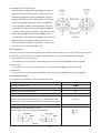
Table 9
Wave length (nm)
Emission duration (s)
> 400
I
< 710
> 2.5 x 10⁻¹
Class II accessible emission limit
(Unit)
(Threshold value)
(Amount)
1.0 x 10⁻³
W
Radiant power
The saw blade unit prevents access of the operator's eye to the laser-emitting aperture less than 65 mm.
In addition, the amount of light exposure (output) is 1 mW or less (about 0.4 mW) at this position. Thus the
Models C 12LSH and C 12RSH satisfy the Class II requirements adequately. There is no ill effect on the
operator's body if looking at the laser line on the workpiece during operation.
CAUTION: (1) Be sure to disconnect the power cord plug from the receptacle before removing the
laser marker for repair. If it is unavoidable to check the operation of the removed
laser marker with the power turned on, face the laser emitting aperture to the ground
to show the laser line on the ground.
(2) Laser radiation when open. DO NOT STARE INTO BEAM OR VIEW DIRECTLY WITH
OPTICAL INSTRUMENTS.
The life span of the laser marker in the Models C 12LCH and C 12RSH is about 3,600 hours. (About 3 years:
5 hours of use/day x 240 days/year)
--- 18 ---
7-5. Ambient Illuminance and Visibility of Laser Line
The visibility of the laser line on the workpiece changes depending on the brightness of the working environment.
Instruct the customer to consider the brightness of the working environment when using the laser marker referring
to the following table.
Table 10 Ambient illuminance and visibility of laser line
Illuminance (lux)
Outdoor
Ambient
conditions
(reference)
3000 or more 3000 or more 3000 - 2500
Under direct
Shaded area
sunlight of fine
in fine weather
weather
Near the
Indoor under
window under
fine weather
fine weather
Indoor
Laser line
Cloudy
weather
Invisible
Visible
Visible
800 - 600
Shaded area
in cloudy
weather
300 - 200
150 - 80
Just before
the sunset in
cloudy
weather
Near the
window under Indoor under
cloudy
cloudy
weather
weather
Visible
Visible
Near the window
under cloudy
weather, just
before the
sunset
Glaring
30 or less
Ink line is
invisible.
Glaring
(The working environment where the illuminance is 200 luxes or less is dark and difficult to operate the Models
C 12LSH and C 12RSH.)
The laser line is invisible under direct sunlight of fine weather. Prepare a shaded area or relocate to a shaded
area to operate the Models C 12LSH and C 12RSH.
7-6. Precautions Concerning Brake (For USA/CAN)
The Models C 12LSH and C 12RSH are equipped with a "brake" that stops running when the switch is turned off.
Normally the operation is stopped in 5 - 6 seconds when the switch is turned off. If it takes 10 seconds or more to
stop, absolutely avoid further use of this machine. In this event, ensure that your customers bring this machine in
their local Hitachi power tools dealer or Hitachi power tools center for servicing.
(1) Be sure to use the carbon brushes dedicated to the Models C 12LSH and C 12RSH (Code No. 999038).
Use of other carbon brushes will adversely affect the brake performance.
(2) If the brake should fail to work, check the carbon brushes. Replace the carbon brushes with new ones if their
length is shorter than 6 mm. If the brake still does not work, replace the armature ass'y.
--- 19 ---
8. ADJUSTMENT AND OPERATIONAL PRECAUTIONS
8-1. Confirmation of Saw Blade Lower Limit Position
The lower limit of the saw blade cutting depth is factory-adjusted so that when the saw blade is fully lowered, its
cutting edge is 9 to 11 mm (23/64" to 7/16") below the upper surface of the turn table in order to cut workpieces
completely without cutting the bottom of the turn table groove. Lower the saw blade and check that it stops at the
correct position (Fig. 26-a). When changing the position of the 8-mm depth adjustment bolt that is the lower limit
position stopper.
Change the position of the 8 mm depth adjustment bolt that is the lower limit position stopper according to the
following procedure.
(1) Make the tip of the 8 mm depth adjustment bolt contact with the hinge.
(2) Turn the 8 mm depth adjustment bolt with a 13-mm wrench to adjust the lower limit position of the saw blade
(Fig. 26-c).
CAUTION: Perform adjustment carefully to ensure that the saw blade does not cut into the turn table.
Fig. 26-a
Fig. 26-b
Fig. 26-c
--- 20 ---
8-2. Confirmation for Use of Sub Fence (A) and Sub Fence (B)
The Models C 12LSH and C 12RSH are equipped with sub fence (A) and sub fence (B).
Use sub fence (A) and sub fence (B) for miter cutting, left and right bevel cutting.
Sub fence (A) and sub fence (B) support the workpiece widely for stable cutting. In the case of right bevel cutting,
raise sub fence (A) as illustrated in Fig. 27-a and turn it clockwise. In the case of left bevel cutting, raise sub
fence (B) as illustrated in Fig. 27-b and turn it counterclockwise.
Fig. 27-a
Fig. 27-b
WARNING: In the case of left bevel cutting, turn sub fence (B) counterclockwise. Unless it is turned
counterclockwise, the main body or saw blade may contact sub fence (B), resulting in an
injury. Be sure to instruct the customers to turn sub fence (B) counterclockwise in the
case of left bevel cutting. In the case of right bevel cutting, turn sub fence (A) clockwise.
Unless it is turned clockwise, the main body or saw blade may contact sub fence (A),
resulting in an injury. Be sure to instruct the customers to turn sub fence (A) clockwise in
the case of right bevel cutting.
--- 21 ---
8-3. Position Adjustment of Laser Line
The laser line is adjusted to the width of the saw blade at the
time of factory shipment. Depending upon the cutting choice,
align the laser line with the left side of the cutting width (saw
blade) or the right side according to the following procedure.
First, make a right-angle ink line on the workpiece that is about
20 mm (13/16") in height and 150 mm (5-7/8") in width.
To cut the right side of the ink line with the saw blade as shown
Fig. 31
in Fig. 31, align the left side of the saw blade with the ink line
on the workpiece and make a groove of about 5 mm deep on
the workpiece to the middle. Hold the grooved workpiece by
the vise as it is and do not move it. (For grooving work, refer to
the Instruction Manual "Groove cutting procedures".)
Light up the laser marker. Turn the adjuster to align the laser
line with the ink line. (Turning the adjuster clockwise will shift
the laser line position to the right and turning counterclockwise
will shift to the left.) (Fig. 32)
Thus the cutting position matches the laser line position. Align
Fig. 32
the ink line on the workpiece with the laser line. When aligning
the ink line, slide the workpiece little by little and secure it by
vise at a position where the laser line overlaps with the ink line
(Fig. 33). Work on the grooving again and check the position
of the laser line. When the ink line and the laser line are
overlapped, the strength and weakness of light will change,
resulting in a stable cutting operation because you can easily
discern the conformity of lines. This ensures the minimum
cutting errors.
Fig. 33
WARNING:
Make sure before plugging the power plug into the receptacle that the main body and the laser marker
are turned off.
Exercise utmost caution in handling a switch trigger for the position adjustment of the laser line, as
the power plug is plugged into the receptacle during operation. If the switch trigger is pulled
inadvertently, the saw blade can rotate and result in unexpected accidents.
Do not remove the laser marker to be used for other purposes.
--- 22 ---
CAUTION:
Laser radiation - Do not stare into beam.
Laser radiation on work table. Do not stare into beam.
If your eye is exposed directly to the laser beam, it can be hurt.
Do not dismantle it.
Do not give strong impact to the laser marker (main body of tool); otherwise, the position of a laser
line can go out of order, resulting in the damage of the laser marker as well as a shortened service life.
Keep the laser marker lit only during a cutting operation. Prolonged lighting of the laser marker can
result in a shortened service life.
NOTE:
Perform cutting by overlapping the ink line with the laser line. When the ink line and the laser line are
overlapped, the strength and weakness of light will change, resulting in a stable cutting operation
because you can easily discern the conformity of lines. This ensures the minimum cutting errors.
In outdoor or near-the-window operations, it may become difficult to observe the laser line due to the
sunlight. Under such circumstances, move to a place that is not directly under the sunlight and
engage in the operation.
Do not tug on the cord behind the motor head or hook your finger, wood and the like around it;
otherwise, the cord may come off and the laser marker may not be lit up.
Instruct the above precautions on the laser marker to the customers.
8-4. How to Use the Vise Assembly
(1) The vise assembly can be mounted on either the left fence {fence (B)} or the right fence {fence (A)} by
loosening 6 mm wing bolt (A).
(2) The screw holder can be raised or lowered according to the height of the workpiece by loosening 6 mm wing
bolt (B). After the adjustment, firmly tighten 6 mm wing bolt (B) and fix the screw holder.
(3) Turn the upper knob and securely fix the workpiece in position (Fig. 34).
WARNING: Always firmly clamp or vise to secure the workpiece
to the fence; otherwise the workpiece might be thrust
from the table and cause bodily harm.
CAUTION: Always confirm that the motor head (see Fig. 1) does
not contact the vise assembly when it is lowered for
cutting. If there is any danger that it may do so,
loosen 6 mm wing bolt (B) and move the vise
assembly to a position where it will not contact the
Fig. 34
saw blade.
--- 23 ---
8-5. Adjustment of Table Insert Position
Table inserts are installed on the turn table. When the machine is shipped from the factory, the table inserts are
positioned so that there is no chance that the saw blade will come in contact with either side of the saw blade slot
even if the machine is used for 45˚ bevel cutting. Before operating the machine, adjust the position of the table
inserts so that the sides of the saw blade align with the edges of the table inserts according to the following
procedure.
Firtst, loosen the three 5 mm machine screws that fasten the table inserts, and temporarily tighten the two
outside screws (front and back). Next, clamp a workpiece (about 200 mm (7-7/8") wide) with the vise assembly
and cut the workpiece. Align the cutting surfaces with the table inserts as shown in Figs. 35-a, 35-b and 35-c and
securely tighten the front and back 5 mm machine screws. Finally, remove the workpiece and securely tighten the
middle 5 mm machine screw.
If adjustment is done as described, workpieces can be cut precisely by aligning the appropriate side edge of the
table inserts with the ink line on the workpiece. Adjust the table inserts as necessary for the type of cutting
desired (right angle or left/right bevel cutting).
Fig. 35-a
Fig. 35-b
Fig. 35-c
--- 24 ---
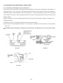
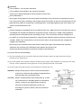
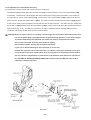
8-6. Cutting Operation
(1) Cutting efficiency will be reduced if a dull saw blade is used,
if an excessively long extension cord is used, or if the wire
Slide securing
knob (A)
Holder (A)
gauge of the extension cord is too small. (For details, refer
Saw
blade
to the Instruction Manual "USE PROPER EXTENSION
CORD".) This is particularly important when cutting
Workpiece
materials with dimensions which are at or near the
maximum capacity for the machine.
(2) The customer should be advised to thoroughly inspect the
Hinge
Fence
Slide pipe
workpiece to ensure that there are no metallic objects (nails
in particular), sand, or other foreign matter in or on the
workpiece. Contacting such foreign matter will not only
Slide securing
knob (B)
shorten the service life of the saw blade, but could cause
serious accident. Should the saw blade tips be broken off,
the tips may fly toward the operator.
(3) Press cutting ( 3 in Fig. 36)
The Models C 12LSH/C 12RSH can be used for press
cutting of workpieces up to 107 mm (4-3/16") square in a
single operation by simply pushing the saw blade section
downward in the same manner as the Model C 12FSA.
Slide hinge (A) to the end of holder (A) and tighten slide
securing knob (A) and slide securing knob (B) securely.
(4) Slide cutting ( 1 to 5 in Fig. 36)
Slide cutting procedures and precautions are described below.
Fig. 36
1 Loosen slide securing knob (A).
2 Grip the handle and pull the saw blade section in the arrow direction (toward the operator).
3 Push the handle downward and cut the workpiece (press cutting).
CAUTION: If the handle is pushed down forcibly and excessively fast, it could cause the saw blade
vibration and partial sliding which would leave unwanted cutting marks on the workpiece.
Instruct the customer to slowly and carefully press down the handle.
4 While pressing down on the handle, slide the saw blade section in the arrow direction and cut the workpiece.
CAUTION Interrupting the cutting operation part way through the material or sliding the saw blade
section in a jerky manner will produce unwanted cutting marks similar to those described in
3 above. As a guide, instruct the customer to cut a workpiece of 30 mm (1-3/16") high and
240 mm (9-7/16") wide in 10 to 15 seconds.
Carefully instruct the customer never, ever to perform slide cutting in the direction toward
the operator (reverse direction of 4 above). Such operation is extremely hazardous, as the
saw blade could ride up over the workpiece and cause the saw blade section to kick upward
unexpectedly, causing possible serious injury.
--- 25 ---
Instruct the customer to always slide the saw blade section toward the fence while cutting, as
shown by arrow 4 in Fig. 36.
5
On completion of the cutting operation, turn the switch off and wait for the saw blade to come to a complete
stop before raising the handle to its original position. Raising the handle while the saw blade is still rotating
may cause unwanted cutting marks on the workpiece.
NOTE:
Techniques to avoid unwanted cutting marks
Uneven and unwanted cutting marks can be avoided by shifting from 3 press cutting to 4 slide
cutting in a single, uninterrupted motion.
Techniques to avoid burnt marks
Burnt marks can be avoided by shifting from 3 press cutting to 4 slide cutting in a single,
uninterrupted motion in the same manner as the above, applying a slight lateral force toward the
cut-off side. Advise the customer that he or she will quickly develop a "feel" and skill for smooth
cutting after performing two or three practice cutting operations.
(5) Miter cutting
Miter cutting is accomplished by turning the turn table. (For details, please refer to the Instruction Manual
"Miter cutting procedures".)
(6) Bevel cutting
Bevel cutting of 0 --- 45˚ to the left or right is accomplished by inclining the motor head section. (For details,
refer to the Instruction Manual "Bevel cutting procedures".)
WARNING: When the workpiece is secured on the left or right side of the blade, the short cut-off
portion will come to rest on the right or left side of the saw blade. Always turn the
power off and let the saw blade stop completely before raising the handle from the
workpiece. If the handle is raised while the saw blade is still rotating, the cut-off piece
may become jammed against the saw blade causing fragments to scatter about
dangerously. When stopping the bevel cutting operation halfway, start cutting after
pulling back the motor head to the initial position. Starting from halfway, without
pulling back, causes the protective cover to be caught in the cutting groove of the
workpiece and to contact the saw blade.
CAUTION: When cutting a workpiece of 75 mm (2-15/16") height in the left 45˚ bevel cutting
position or a workpiece of 50 mm (1-15/16") height in the right 45˚ bevel cutting
position, adjust the lower limit position of the motor head so that the gap between the
lower edge of the motor head and the workpiece will be 2 to 3 mm (3/32" to 1/8") at the
lower limit position (refer to the Instruction Manual "Checking the saw blade lower limit
position").
--- 26 ---
(7) Compound (miter + bevel) cutting
Compound (miter + bevel) cutting can be accomplished by combining the miter cutting and bevel cutting
operations described in paragraphs (5) and (6) above. (For details, refer to the Instruction Manual
"Compound cutting procedures".) When the saw blade is inclined 45˚ to the left, the turn table can be turned
up to 45˚ to the left, and up to 31˚ to the right because hinge (A) contacts fence (B). When the saw blade is
inclined 45˚ to the right, the turn table can be turned up to 31˚ to the left, and up to 45˚ to the right because
hinge (A) contacts fence (A).
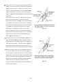
(8) Cut surface quality during miter/bevel cutting
The quality of the cut surface depends on the type of cutting
operation (miter or bevel), the type and sharpness of the saw
blade, whether the workpiece is cut to the left or right, and
various other factors. In miter and bevel cutting in particular,
cutting is performed across the wood grain, so the condition of
the cut surface depends on whether the wood is cut with or
against the grain. This is the same as when using electric
portable planers. Customers should be advised of these
phenomena so that they understand that in cases when the cut
surface may not be as smooth as expected or hoped for, it is
not caused by the performance of the saw blade or the Models
Fig. 37
C 12LSH/C 12RSH.
In the cutting examples illustrated in Fig. 37, the cut surfaces on the sides marked A (cut with the grain) are
better than those on the sides marked B .
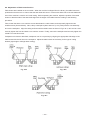
(9) Crown molding cutting
This machine can cut two types of crown molding workpieces by combining the miter and bevel cutting
operations.
Fig. 38 shows two common crown molding types having angles of (θ) 38˚ and 45˚. For the typical crown
molding fittings, see Fig. 39.
Fig. 38
Fig. 39
The table below shows the miter angle and the bevel angle settings that are ideal for the two crown molding
types.
NOTE: For convenience, positive stops are provided for the miter setting (left and right 31.6˚)
positions. (For USA/CAN)
--- 27 ---
For miter cut setting
If the turn table has been set to either of the angles described, move the turn table adjusting side handle a little
to the right and left to stabilize the position and to properly align the miter scale and the tip of the indicator
before the operation starts. Then tighten the side handle.
For bevel cut setting
Turn the clamp lever on bevel section to the right and left and check that the position is stable and the angle
scale and the tip of the indicator are properly aligned. Then tighten the clamp lever.
Table 11
Type of
crown molding
To process crown molding at
positions 1 and 4 in Fig. 39
To process crown molding at
positions 2 and 3 in Fig. 39
Miter angle
setting
Miter angle
setting
Bevel angle
setting
Bevel angle
setting
45˚ type
Right 35.3˚
Left 30˚
Right 30˚
Left 35.3˚
Left 30˚
Right 30˚
38˚ type
Right 31.6˚
Left 33.9˚
Right 33.9˚
Left 31.6˚
Left 33.9˚
Right 33.9˚
(1) Setting to cut crown moldings at positions 1 and 4 in Fig. 39 (See Fig. 40, tilt the head to the left.):
1 Turn the turn table to the right and set the miter angle as follows:
For 45˚ type crown moldings: 35.3˚
For 38˚ type crown moldings: 31.6˚
2 Turn the head to the left and set the bevel angle as follows:
For 45˚ type crown moldings: 30˚
For 38˚ type crown moldings: 33.9˚
3 Position the crown molding so that the lower surface ( A in Fig. 38) contacts the fence as indicated in
Fig. 42.
(2) Setting to cut crown moldings at positions 2 and 3 in Fig. 39 (See Fig. 41, tilt the head to the left.):
1 Turn the turn table to the left and set the miter angle as follows:
For 45˚ type crown moldings: 35.3˚
For 38˚ type crown moldings: 31.6˚
2 Tilt the head to the left and set the bevel angle as follows:
For 45˚ type crown moldings: 30˚
For 38˚ type crown moldings: 33.9˚
3 Position the crown molding so that the lower surface ( B in Fig. 38) contacts the fence as indicated in
Fig. 43.
--- 28 ---
Fig. 40
Fig. 41
Fig. 43
Fig. 42
(3) Setting to cut crown moldings at positions 1 and 4 in Fig. 39 (See Fig. 44, tilt the head to the right.):
1 Turn the turn table to the right and set the miter angle as follows:
For 45˚ type crown moldings: 35.3˚ ( mark)
For 38˚ type crown moldings: 31.6˚ ( mark)
2 Tilt the head to the right and set the bevel angle as follows:
For 45˚ type crown moldings: 30˚ ( mark)
For 38˚ type crown moldings: 33.9˚ ( mark)
3 Position the crown molding so that the upper surface ( B in Fig. 38) contacts the fence as indicated in
Fig. 46 .
(4) Setting to cut crown moldings at positions 2 and 3 in Fig. 39 (See Fig. 45, tilt the head to the right.):
1 Turn the turn table to the left and set the miter angle as follows:
For 45˚ type crown moldings: 35.3˚ ( mark)
For 38˚ type crown moldings: 31.6˚ ( mark)
2 Tilt the head to the right and set the bevel angle as follows:
For 45˚ type crown moldings: 30˚ ( mark)
For 38˚ type crown moldings: 33.9˚ ( mark)
3 Position the crown molding so that the lower surface ( A in Fig. 38) contacts the fence as indicated in
Fig. 47.
--- 29 ---
Fig. 45
Fig. 44
Fig. 46
Fig. 47
Cutting method of crown molding without tilting the saw blade
(1) Crown molding stopper (L) and (R) (optional
accessories) allow easier cuts of crown molding without
tilting the saw blade. Install them to both sides of the
Crown molding vise ass'y Crown molding stopper (R)
(optional accessory)
(optional accessory)
6 mm knob
bolt
6 mm knob bolt
base as shown in Fig. 48-a. After inserting, tighten the
6 mm knob bolts to secure the crown molding guides.
[ Optional accessories used ]
Crown molding vise ass'y
6 mm wing bolt
(Including crown molding stopper (L))
Crown molding stopper (L)
Crown molding stopper (L)
(optional accessory)
Fig. 48-a
Crown molding stopper (R)
(2) The crown molding vise ass'y (optional accessory) can
be mounted on either the left fence (fence (B)) or the
right fence (fence (A)). It can unite with the slope of the
crown molding and vise can be pressed down. Then
turn the upper knob, as necessary, to securely attach
the crown molding in position. To raise or lower the vise
assembly, first loosen the 6 mm knob bolt. As shown in
Fig. 48-b, the vise shaft has three locking grooves into
which the tip of the 6 mm wing bolt is designed to fit in
order to lock the screw holder in the desired position.
Fig. 48-b
--- 30 ---
To ensure that the tip of the 6 mm wing bolt is properly aligned with the desired locking groove on the vise
shaft, simply align the upper surface of the fence to either of three v-grooves on the vise shaft surface or to the
lower surface of the screw holder. Therefore, the vise assembly can be attached in either of three positions to
ensure proper height.
WARNING: Always firmly clamp or vise to secure the crown molding to the fence; otherwise the
crown molding might be thrust from the table and cause bodily harm. Do not perform
bevel cutting. The main body or saw blade may contact the sub fence, resulting in an
injury.
CAUTION: Always confirm that the motor head does not contact the crown molding vise ass'y
when it is lowered for cutting. If there is any danger that it may do so, loosen the 6 mm
knob bolt and move the crown molding vise ass'y to a position where it will not contact
the saw blade.
Position crown molding with its WALL CONTACT EDGE against the guide fence and its CEILING CONTACT
EDGE against the crown molding stoppers as shown in Fig. 48-b. Adjust the crown molding stoppers
according to the size of the crown molding. Tighten the 6 mm wing bolt to secure the crown molding stoppers.
Refer to Table 12 below for the miter angle.
Table 12
For inside corner
Position in Fig. 36
Miter angle
1
Right 45˚
2
Left 45˚
Save the right side of blade.
Save the left side of blade.
Save the right side of blade.
3
For outside corner
4
Finished piece
Right 45˚
--- 31 ---
Save the left side of blade.
8-7. Digital Display Panel (Only Model C 12LSH)
Fig. 49
Fig. 50-a
Fig. 50-b
(1) Turning on the digital display switch shows 0˚ for both miter and bevel angle, regardless of main unit angle.
(2) Align the main unit angle with the tilt angle (0˚) and miter angle (0˚) and hold down their reset buttons for at
least 0.2 seconds.
(3) Turning on the laser marker switch while the digital display switch is on, lights up the laser marker. (On the
Model C 12RSH, only the laser marker switch.)
CAUTION: When operating the digital panel, have the motor head section at the initial position and the
blade stopped.
--- 32 ---
NOTE:
Instruct the customers to align the main unit to the miter angle 0˚ and the bevel angle 0˚ and hold
down their reset buttons for at least 0.2 second before starting to cut. If customers press the
digital display switch to ON without aligning the main unit to 0˚, then the figures appearing on
the digital display and the main unit angle will not match.
The laser marker will not light up if the digital display switch is turned off. (Only Model C 12LSH)
Do not use the main unit near equipment that generates electrical noise such as generators.
Electrical noise might cause faulty readings or operation on the digital display.
If there is a malfunction on digital display because of power supply noise, turn the digital display
switch OFF and perform the procedures (1) and (2) in 8-8 to reset it.
The digital display may show a deviated value if the flush surfaces for the bevel angle adjustment
bolt are worn.
Instruct the customers to adjust the angle according to section 9-1 in this case.
CAUTION: If the figure shown on the miter angle digital display is different from the positive stop angle
(for example, 45.0˚
45.5˚, 31.6˚
32.0˚) then the positive stop has probably deviated
slightly from its correct position.
If this happens, do as follows.
(1) Move the turn table left and right with the side handle loosened, and set the turn table to
the correct position.
(2) If the figures on the display and positive stop still do not match, then return the turn
table to the 0˚ position. Next move the turn table left and right with the side handle
loosened as shown in Fig. 50-b. After setting it to the correct position 0˚, press the reset
button again.
8-8. Precautions Concerning Electronic Condition
Operate the machine with correct voltage supply. Large voltage drops caused by an unstable power supply may
cause the lower output of the motor and affect efficient cutting. Advise the customer to check the power supply
before operating the machine. In addition, the customer should be advised to pay particular attention to the
following points:
If an extension cord is used, it should be kept as short as possible and within the requirements listed in the
Instruction Manual "USE PROPER EXTENSION CORD".
[Reason] An excessively long extension cord causes voltage drop.
--- 33 ---
9. ADJUSTMENT OF COMPONENTS
9-1. Bevel Angle Adjustment
Before the power tool is shipping from the factory, the height of 8 mm bolt (A), 8 mm bolt (B) and 8 mm set screw
is adjusted so that the saw blade section (head) will stop at 0˚ (right angle), 45˚ to the left, and 45˚ to the right.
To change the head stop positions, instruct the customer to adjust the height of 8 mm bolt (A), 8 mm bolt (B) and 8
mm set screw by turning them. For example, to change the 45˚ to the right stopper, pull set pin (A) in the direction
indicated by the arrow in Fig. 51-b, and tilt the head to the right. When setting the head to 0˚ position, be sure to
replace set pin (A) (insert it in the opposite direction from that indicated by the arrow in Fig. 51-b).
Fig. 51-b
Fig. 51-a
CAUTION: If there is any clearance between the tip of 8 mm set screw (stopper for 0˚) and set pin (A),
the angle of the saw blade relative to the upper surface of the turn table may not be an
exact right angle. (8 mm bolt (A), 8 mm bolt (B) and 8 mm set screw are located at the rear
of the turn table.) Press down on holder (A) and lock it in position with the clamp lever so
that there is no clearance between set pin (A) and 8 mm set screw.
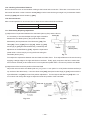
9-2. Ball Bushing (Linear Bearing)
(1) Structure of the ball bushing
The ball bushing is commonly called a linear
ball bearing. Inside the bearing is elongated
guide grooves in which steel balls circulate
and roll when a load is applied. (as indicated
by the arrow marks in Fig. 52). This type of
device is widely used in automated machine
tools. The advantage of the ball bushing is
that its friction coefficient remains largely
Fig. 52
unchanged even when the load is increased,
ensuring smooth sliding movement.
In addition, slide pipe (B), made of bearing steel and heat treated to a high degree of hardness (HRC 62 to
65), is highly resistant to wear.
Sales persons should have a good understanding of the structure and rugged characteristics of this
exceptional mechanism to enhance sales promotion.
--- 34 ---
(2) Lubrication
If it is necessary to replace the ball bushing, apply approximately 2 grams (0.1 oz) of grease (Nippeco SEP
3A) on the steel balls and within the guide grooves of the new ball bushing. If grease is not applied, it will
shorten the service life of the ball bushing, and subsequent abrasive contact between the steel balls and slide
pipe (B) will cause abnormal noise during slide cutting operations. Customers should be instructed to
thoroughly remove sawdust and other foreign matter from slide pipe (A) and slide pipe (B) and liberally coat
them with machine oil at least once a month.
10. PACKING
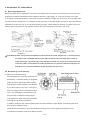
(1) Preparation before packing
Remove the dust bag from the main body. Turn the turn table to the right 57˚ and secure the side handle.
Push the guard back (Fig. 53).
Turn table
Guard
Side handle
Fig. 53
(2) How to install packings (B) and (D)
Slide the head to the midpoint between holder (A) and the support at the front of the main unit, and secure it
with the slide securing knob. Place packing (B) under the gear case and push the head down. Insert the
locking pin while pressing packing (B) to secure the gear case in position. Insert packing (D) into the motor
housing (Fig. 54).
Head
Slide securing knob
Packing (B)
Fig. 54
--- 35 ---
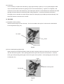
(3) How to install packings (E) and (F)
Put the main body mounted with packing (B) and packing (D) in the carton box aligning with the base packing.
Cover the support at the rear of the main unit, housing and switch handle with two poly sheets. Insert packing
(F) into the clearance near the switch handle at the front of the main unit and packing (E) into the clearance
near the support at the rear of the main unit from above. Put the cord through the groove "A" of packing (E)
and insert the tip of the cord into the clearance "B" between the sleeve and packing (E). (Check that cable tag
(B) is securely placed in "B" portion.) Place the accessories in the space of packing (F) (Fig. 55).
Carton box
Packing (E)
Sleeve
A
Packing (F)
Packing (D)
Fig. 55
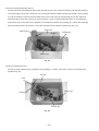
(4) How to install the top pad
Put the top pad on packing (D), packing (E) and packing (F). Close he lids of the carton box and bind them
together (Fig. 56).
Top pad
Cord
B
Packing (F)
Packing (E)
Packing (D)
Fig. 56
--- 36 ---
11. PRECAUTIONS IN DISASSEMBLY AND REASSEMBLY
11-1. Precautions in Disassembly and Reassembly of the Laser Marker
Do not stare into the laser emitting aperture during disassembly and reassembly of the laser marker. Do not
observe beam directly with an optical instrument. Use of controls or adjustments or performance of procedures
other than those specified in this TECHNICAL DATA AND SERVICE MANUAL and the Instruction Manual may
result in hazardous radiation exposure.
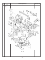
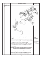
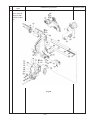
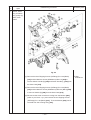
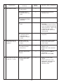
11-2. Disassembly
Special attention in disassembly should be given to the following items. The circled numbers in the figures and
the [Bold] numbers in the descriptions below correspond to the item numbers in the parts list and exploded
assembly diagram of the Model C 12LSH. For the Model C 12RSH, refer to the parts list separately.
* Be sure to first disconnect the power plug when performing disassembly or replacement of the saw blade.
Item
No.
Disassembly
spots
1
Turn table, base
ass'y
Disassembly procedure
Fig. 57
--- 37 ---
Necessary tools
Item
No.
Disassembly
spots
1
Turn table, base
ass'y
Disassembly procedure
Fig. 58
--- 38 ---
Necessary tools
Item
No.
Disassembly
spots
1
Turn table, base
ass'y
Disassembly procedure
Necessary tools
(1) Remove the Knob Bolt [172], Guard Ass'y [176] and Guard Holder
[178] from Holder (A) [145].
(2) Remove the two Flat Hd. Screws M6 x 25 [53] by turning the Nylon 10 mm wrench
Nut M6 [47] with a 10-mm wrench. Remove Plate (A) [93], Sub
Fence (A) Ass'y [94], Plate (B) [48] and Sub Fence (B) Ass'y [45]
Phillips
screwdriver
from Fence (A) [96] and Fence (B) [51].
(3) Remove the four Bolts (W/Washers) M8 x 35 (Black) [50] and
remove Fence (A) [96] and Fence (B) [51] from the Base Ass'y
13-mm box
wrench
[59].
(4) Remove the two Machine Screws (W/Washers) M5 x 16 (Black)
[139] and remove the Side Cover [140] from the Support [134].
Phillips
screwdriver
(5) Remove the Machine Screw M4 x 12 [136] and remove Cover (D)
[138] from Holder (A) [145].
(6) Disconnect the connector that connects Cord (B) [168] and Cord
(C) [18].
(7) Remove the Machine Screw M4 x 12 [131] and remove the Nylon
Clip [133] from Holder (A) [145].
(8) Loosen the Clamp Lever [156]. Holding the Grip [174], pull Set Pin
(A) [162] forward (toward the operator) to release the right stopper
and tilt the head to the right by 45 degrees.
(9) Remove the Machine Screw (W/Washers) M5 x 16 (Black) [65] and
remove Knob (B) [63] from Holder (A) [145].
NOTE: Knob (B) [63] cannot be removed unless the head is
inclined to the right by 45 degrees and the concave
portion at the rear of the Turn Table [26] is aligned with the
pinion of Knob (B) [63].
(10) Return the head to the right-angle position. Holding the Grip
[174], pull Set Pin (A) [162] backward to set the right stopper and
secure with the Clamp Lever [156].
(11) Remove the four Machine Screws M4 x 12 [1] and remove Cover
(B) [3] from the rear of the Turn Table [26].
(12) Disconnect the connector that connects the Encoder [16] and
Cord (C) [18].
(13) Remove the Machine Screw M5 x 20 [13] and remove the
Encoder [16] from the Turn Table [26].
--- 39 ---
Phillips
screwdriver
Item
No.
1
Disassembly
spots
Disassembly procedure
Necessary tools
Turn table, base NOTE: Do not lose Spring (C) [15] as Spring (C) [15] pops out
ass'y
when removing the Encoder [16]. When reinstalling the
Encoder [16] to the Turn Table [26], move the Encoder [16]
away from Gear (A) [8] and secure it at this position with
the Machine Screw M5 x 20 [13] temporarily. Then loosen
the Machine Screw M5 x 20 [13] (about one turn) and move
the Encoder [16] to mesh with Gear (A) [8].
(14) Remove the Machine Screw M4 x 12 [10] and remove the Nylon
Clip [12] from the Turn Table [26].
(15) Loosen the Clamp Lever [156] and remove the two Hex. Socket
Hd. Bolts M6 x 50 [159] to remove Stopper Holder (C) [160] and
5-mm hex. bar
wrench
Stopper (C) [161] from Holder (A) [145].
NOTE: The head cannot be secured at the inclined position if the
Clamp Lever [156] is removed. Be careful not to incline the
head to the left during disassembly.
(16) Incline the head to the left by 45 degrees and remove the Machine Phillips
screwdriver
Screw M4 x 16 [171] to remove the Cord Cover [169] from Holder
(A) [145]. Remove the Seal Lock Hex. Socket Set Screw M6 x 10
[64] and return the head to the right-angle position. Make a flatblade screwdriver contact with the end surface of the Holder Shaft
Flatblade
screwdriver
[6] and tap the screwdriver with a plastic hammer to remove the
Holder Shaft [6] from the Turn Table [26]. Then the head can be
Plastic hammer
removed together with Holder (A) [145] from the Turn Table [26].
NOTE: Be careful of handling the heavy head during disassembly.
(17) Turn the base upside down and remove the five Machine Screws
M5 x 20 [83] from the back of the Turn Table [26]. Remove Shaft
Phillips
screwdriver
Holder (A) [75] and Shaft Holder (B) [74] from the Turn Table [26].
(18) Turn the base upside down and remove the Machine Screw
M4 x 12 [66] to remove the Indicator [68] from the Turn Table [26].
(19) Remove the three Flat Hd. Screws M4 x 16 [20] and remove Gear
(A) [19] from the Turn Table [26].
(20) Remove the six Machine Screws M5 x 16 (Black) [60] and remove
Table Insert (A) [62] and Table Insert (B) [61] from the Turn Table
[26].
(21) Remove the Shaft (B) [23] and remove the Turn Table [26] from
19-mm box
wrench
the Base Ass'y [59].
(22) Turn the Turn Table [26] upside down and remove the Side Handle
[92] to remove Shaft (A) [91] from the Turn Table [26].
--- 40 ---
Item
No.
Disassembly
spots
1
Turn table, base
ass'y
Disassembly procedure
Necessary tools
(23) Remove the Machine Screw M4 x 8 [34] and remove Spring (E)
[27], Stopper (A) [28] and Pin Cover [32] from the Turn Table [26].
(24) Remove the Machine Screw M4 x 8 [34] and pull out the Lever
Shaft [85] to remove the Lever [89], Spring (D) [90] and Shaft (C)
[88] from the Turn Table [26].
(25) Remove the Machine Screw M4 x 8 [34] and remove Cover (B)
[87] and Spacer (A) [69] from the Turn Table [26].
(26) Remove the Machine Screw M4 x 8 [34] and remove the Dust
Cover [97] from the Turn Table [26].
(27) Remove the three Machine Screws M4 x 12 [10] and remove the
three Nylon Clips [12] from the Turn Table [26].
Phillips
screwdriver
(28) Disconnect the connector that connects the Encoder [35] and
Cord (C) [18].
(29) Remove the Machine Screw M5 x 20 [31] and remove the
Encoder [35] from the Turn Table [26].
NOTE: Do not lose Spring (C) [29] as Spring (C) [29] pops out
when removing the Encoder [35]. When reinstalling the
Encoder [35] to the Turn Table [26], move the Encoder [35]
away from Gear (A) [56] and secure it at this position with
the Machine Screw M5 x 20 [31] temporarily. Then loosen
the Machine Screw M5 x 20 [31] (about one turn) and move
the Encoder [35] to mesh with Gear (A) [56].
(30) Remove the two Machine Screws (W/Sp. Washer) M5 x 16 [52]
and remove Gear (A) [56] from the Turn Table [26].
(31) Remove the Bolt M6 x 10 [55] and pull out the Holder [54] from
the rear of the Base Ass'y [59].
(32) Turn the Base Ass'y [59] upside down and pull out the four Base
Rubbers [58].
--- 41 ---
10-mm wrench
Item
No.
Disassembly
spots
2
Protective cover,
link
Disassembly procedure
Necessary tools
Fig. 59
(1) Remove the two Machine Screws (W/Washers) M5 x 12 (Black)
[264] and remove the Spindle Cover [265] from the Gear Case
[275].
Phillips
screwdriver
(2) Remove Bolt (A) M10 [284] with the Box Wrench 17mm [501].
Remove the Washer (B) [285], TCT Saw Blade [286] and Washer
(A) [287] in this order from the Spindle Ass'y [292].
(3) Remove the two Flat Hd. Screws M4 x 10 [288]. Remove the
Cover [289] and the Protective Cover [290] from the Bearing
Holder [294].
NOTE: Be sure to release the hook of Return Spring (A) [291]
from the groove of the Protective Cover [290] then
remove the Protective Cover [290] from the Bearing
Holder [294].
(4) Remove the Machine Screw M5 x 12 [188] and remove the
Spacer [189] and the Link [190] from Hinge (A) [173].
--- 42 ---
17-mm box
wrench
(standard
accessory)
Item
No.
3
Disassembly
spots
Disassembly procedure
Gear case,
spring, support,
hinge (A), ball
bushing, holder
(A)
Fig. 60
--- 43 ---
Necessary tools
Item
No.
Disassembly
spots
3
Gear case,
spring, support,
hinge (A), ball
bushing, holder
(A)
Disassembly procedure
(1) Remove the Machine Screw M4 x 12 [276] and remove the Nylon
Clip [278] from the Gear Case [275] (head).
(2) Remove the Seal Lock Hex. Socket Hd. Bolt M5 x 10 [150].
Necessary tools
Phillips
screwdriver
4-mm hex. bar
wrench
NOTE: The Seal Lock Hex. Socket Hd. Bolt M5 x 10 [150] acts as
the upper limit stopper of the Gear Case [275] (head).
Be careful that the Gear Case [275] (head) is raised by the
force of the Spring [152] when the Seal Lock Hex. Socket
Hd. Bolt M5 x 10 [150] is removed.
(3) Remove the Seal Lock Hex. Socket Set Screw M6 x 10 [64]. Make 3-mm hex. bar
wrench
a flat-blade screwdriver contact with the end surface of Hinge Shaft
(A) [186] and lightly tap the screwdriver with a plastic hammer to
remove Hinge Shaft (A) [186].
NOTE: Be sure to hold the Gear Case [275] (head) with hand
during disassembly to prevent the Gear Case [275] (head)
Flat-blade
screwdriver
from being dropped when removing Hinge Shaft (A) [186]
from the hole of the Gear Case [275] (head).
Plastic hammer
Then the Spring [152] and the Sleeve [151] can be removed from
the Gear Case [275] (head).
(4) Remove the Seal Lock Hex. Socket Set Screw M6 x 10 [64] and
remove Shaft (D) [167] from the Support [134] at the rear.
(5) Remove the two Hex. Socket Set Screws M8 x 10 [135] from the
Support [134] at the front (operator side). Lightly tap the Support
[134] outward with a plastic hammer to remove it from Slide Pipe
3-mm hex. bar
wrench
4-mm hex. bar
wrench
Plastic hammer
(A) [149] and Slide Pipe (B) [166].
(6) Loosen Knob Bolt M6 x 25 [146] at the top of Hinge (A) [173] and
slide Hinge (A) [173] to the front (operator side) to remove it from
Slide Pipe (A) [149] and Slide Pipe (B) [166]. Then slide the rear
Support [134] backward with Slide Pipe (A) [149] and Slide Pipe
(B) [166] mounted and remove it from Holder (A) [145].
(7) Remove the Seal Lock Hex. Socket Set Screw M6 x 10 [148] from
the side of Hinge (A) [173]. Remove the Bushing [143] from Hinge
3-mm hex. bar
wrench
(A) [173].
NOTE: Prepare a shaft of 31 mm in diameter and 50 mm in length.
Make the shaft contact with the end surface of the Bushing
[143] and lightly tap the shaft with a plastic hammer to
remove the Bushing [143] from Hinge (A) [173].
--- 44 ---
φ31 x 50 mm
shaft
Plastic hammer
Item
No.
Disassembly
spots
3
Gear case,
spring, support,
hinge (A), ball
bushing, holder
(A)
Disassembly procedure
(8) Remove the Machine Screw M4 x 8 [141]. Lightly tap the end
surface of Hinge (A) [173] with a plastic hammer to remove the
Necessary tools
Phillips
screwdriver
Ball Bushing [144].
(9) Remove the Machine Screw M4 x 8 [184]. Push the Stopper Pin
Ass'y [182] toward the inside of Hinge (A) [173] to remove the
Stopper Pin Ass'y [182].
(10) Remove the two Machine Screws (W/Washers) M4 x 12 (Black)
[163] and remove the two Indicators [164] from Holder (A)
[145].
(11) Remove the Machine Screw (W/Washers) M5 x 16 (Black) [175]
and remove the Grip [174] and Set Pin (A) [162] from Holder
(A) [145].
(12) Remove the Seal Lock Hex. Socket Set Screw M6 x 10 [148]
3-mm hex. bar
wrench
from the side of Holder (A) [145]. Remove the Bushing [143]
from Holder (A) [145].
NOTE: Prepare a shaft of 31 mm in diameter and 50 mm in
length. Make the shaft contact with the end surface of
the Bushing [143] and lightly tap the shaft with a plastic
φ31 x 50 mm
shaft
Plastic hammer
hammer to remove the Bushing [143] from Holder (A)
[145].
(13) Remove the Machine Screw M4 x 8 [141]. Lightly tap the end
surface of Holder (A) [145] with a plastic hammer to remove the
Ball Bushing [144].
--- 45 ---
Phillips
screwdriver
Item
No.
Disassembly
spots
4
Belt, pinion ass'y,
spindle ass'y
Disassembly procedure
Necessary tools
Fig. 61
(1) Remove the four Machine Screws (W/Washers) M5 x 25 (Black)
[242] and remove the Pulley Cover [317] from the Gear Case
Phillips
screwdriver
[275].
(2) Pull the Belt (200H13) 16 x 508 [310] outward and turn it to remove
from Pulley (A) [307] and Pulley (B) [305].
(3) Remove the two Machine Screws (W/Washers) M5 x 20 (Black)
[313] and remove Bearing Holder (B) [312] by lightly tapping the
Gear Case [275] with a plastic hammer.
(4) Remove the two Flat Hd. Screws M4 x 10 [304] and tap the Gear
Case [275] lightly with a plastic hammer to remove the Pinion Ass'y
[300].
(5) Remove the Machine Screw M4 x 8 [316] and remove the Stopper
Pin [314] and the Lock Spring [271] from the Gear Case [275].
NOTE: Be careful when removing the Machine Screw M4 x 8 [316]
because the Stopper Pin [314] and the Lock Spring [271]
pop out from the Gear Case [275].
(6) Remove the two Machine Screws M5 x 20 [296] and remove the
Spindle Ass'y [292] by lightly tapping the Gear Case [275] with a
plastic hammer.
--- 46 ---
Plastic hammer
Item
No.
5
Disassembly
spots
Disassembly procedure
Necessary tools
Monitor, stator
ass'y, armature
ass'y, pulley (A),
switch, laser
marker
Fig. 62
(1) Remove the three Tapping Screws (W/Flange) D4 x 20 (Black)
[241] and the Machine Screw (W/Washers) M5 x 10 [262] to
remove Switch Handle (R) [269] and Switch Handle (L) [263] from
the Gear Case [275].
(2) Remove the three Tapping Screws (W/Flange) D4 x 20 (Black)
[241] and the Machine Screw (W/Washers) M5 x 25 (Black) [242]
to remove Handle (R) [238] from the Gear Case [275].
(3) Disconnect the three connectors coming from the Monitor [260]
(white: 2 pcs. black: 1 pc.) and remove the two Tapping Screws
(W/Flange) D4 x 30 (Black) [261]. Then the Monitor [260] can be
removed from the Housing Ass'y [251].
--- 47 ---
Phillips
screwdriver
Item
No.
Disassembly
spots
5
Monitor, stator
ass'y, armature
ass'y, pulley (A),
switch, laser
marker
Disassembly procedure
(4) Cut the internal wires at the root of the three Connectors 50092
Necessary tools
Nippers
[267] that crimp the internal wire coming from the Stator Ass'y 120V
[253] and the internal wire at the root of one Connector 50092
[267] that crimps the Cord [235] and Internal Wire (A) [266].
Be sure to cut each internal wire at the root. Otherwise, it is
impossible to perform wiring at repair because these internal wires
become short.
(5) Disconnect the connector that connects the Switching Power
Supply [233] with Internal Wire (B) [236].
(6) Disconnect the connector that connects the cord of the Laser
Marker [198] with Internal Wire (B) [236].
(7) Remove the Cord Bush [237] from Handle (L) [231]. The Cord
Bush [237] can be removed from the cord of the Laser Marker
[198] by opening the Cord Bush [237].
(8) Remove the Tapping Screw (W/Flange) D4 x 16 [234] and remove
the Switching Power Supply [233] from Handle (L) [231].
Phillips
screwdriver
(9) Remove the Tapping Screw (W/Flange) D5 x 25 (Black) [232] and
remove Handle (L) [231] from the Gear Case [275].
(10) Removal of the Stator Ass'y 120V [253]:
(a) After the above steps from (1) to (9), remove the Brush Cap [243]
with a flat-blade screwdriver and take out the Carbon Brush [244].
Flatblade
screwdriver
Then the Housing Ass'y [251] can be removed from the Gear Case
[275].
(b) Remove the Fan Guide [258] from the Housing Ass'y [251].
Remove the two Hex. Hd. Tapping Screws D5 x 50 [255] that
secure the Stator Ass'y 120V [253] to the Housing Ass'y [251].
Remove the two Brush Terminals [252] from the Brush Holder
Phillips
screwdriver
[245].
(c) Remove the End Plate [254]. Pull out the Stator Ass'y 120V [253]
Plastic hammer
by lightly tapping the Housing Ass'y [251] at the surface where the
Gear Case [275] is mounted with a plastic hammer.
(11) Removal of the Armature Ass'y 120V [256]:
(a) Remove the Housing Ass'y [251] from the Gear Case [275]
according to the procedure of Item No. 5-(10).
(b) Remove the Armature Ass'y 120V [256] by lightly tapping the Gear
Case [275].
(12) Removal of Pulley (A) [307]:
(a) Loosen the Nut M10 [309] of the Armature Ass'y 120V [256] that
was removed in the above step (11) and remove Pulley (A) [307].
--- 48 ---
17-mm wrench
Item
No.
Disassembly
spots
5
Monitor, stator
ass'y, armature
ass'y, pulley (A),
switch
Disassembly procedure
Necessary tools
(13) Removal of the Switch (3P Faston Type) W/O Lock [268]:
(a) Remove Switch Handle (R) [269] and Switch Handle (L) [263] from
the Gear Case [275] according to the procedure of Item No. 5-(1).
Then the Switch (3P Faston Type) W/O Lock [268] can be
removed.
(b) Internal Wire (A) [266] is provided with a claw to prevent coming off
on its connector. When removing Internal Wire (A) [266] from the
Switch (3P Faston Type) W/O Lock [268], pull out Internal Wire (A)
[266] while pressing the claw.
6
Laser marker
Fig. 63
(1) Remove the Machine Screw M4 x 8 [179] and remove the Cover
[181] from the rear of Hinge (A) [173].
(2) Remove the three Machine Screws M4 x 12 [205] and remove
Plate (A) [202] and Cover (A) [201] from Hinge (A) [173].
(3) Remove the Adjuster [191] and push the Clutch Screw [193] from
behind Hinge (A) [173]. Then Holder (B) [207] can be removed
together with the Laser Marker [198].
NOTE: At this time, the Spring [206] and the Clutch Spring [197]
pop out. Be careful not to lose them.
(4) Remove the Clutch Screw [193]. Then the Laser Marker [198]
can be removed from Holder (B) [207].
NOTE: At this time, the two Springs [199] pop out. Be careful
not to lose them.
--- 49 ---
Phillips
screwdriver
Item
No.
7
Disassembly
spots
Vise ass'y
Disassembly procedure
Necessary tools
Phillips
screwdriver
(1) Remove the Wing Bolt [38] to remove the
Vise Shaft [44].
(2) Remove the Machine Screw (W/Washers)
M5 x 12 (Black) [43] to remove the Vise
Plate [42] and the Washers [41].
(3) Remove the Knob Bolt M10 [39] from the
Screw Holder [40].
Fig. 64
--- 50 ---
11-3. Reassembly
Reassembly can be accomplished by following the disassembly procedures in reverse. However, special
attention should be given to following items.
(1) Prior to reassembly, measure the insulation
resistance of the armature, stator, switch and
other electrical components and confirm that the
Back of the turn table
insulation resistance of each part is more than
5 M Ω.
(2) When replacing the Spring [152], apply 3 grams
of Hitachi Motor Grease to the inner
circumference of the new spring prior to
assembly.
(3) When replacing or reassembling the Liner [98],
ensure it is positioned and assembled as
illustrated in Fig. 65. In addition, coat 8 grams of
Hitachi Motor Grease on the liner sliding portion
of the Turn Table [26].
Fig. 65
(4) When replacing the Laser Marker [198], screw the two Seal Lock Hex. Socket Set Screws M5 x 6 [200] into
the Laser Marker [198]. To adjust the accuracy of the Laser Marker [198] easily, protrude the tips of the two
Seal Lock Hex. Socket Set Screws M5 x 6 [200] about 1.5 mm from the Laser Marker [198] using the 2.5-mm
hex. bar wrench so that Holder (B) [207] and the Laser Marker [198] become almost parallel as shown in Fig.
66-a and Fig. 66-b. Refer to "11-10. Adjustment of Lase Marker Accuracy" for adjustment of the laser marker
accuracy.
Cross section viewed from the front
Fig. 66-b
Fig. 66-a
--- 51 ---
11-4. Wiring Diagram
Carefully ensure that wiring is accomplished as illustrated below. As incorrect wiring will result in lack of rotation,
reverse rotation or other malfunctions, close attention is absolutely necessary.
WARNING: Be sure to turn off the two switches (w/cover) on the top of the Monitor [260] (Model
C 12LSH), or turn off the switch (w/cover) on the side of Handle (R) [238] (Model C 12RSH)
and unplug the power cord plug from the receptacle before replacing the Laser Marker
[198] and the Switching Power Supply [233]. Do not disconnect the connector that
connects the Laser Marker [198] with the Switching Power Supply [233] while the Laser
Marker [198] is lighting. Otherwise, the Laser Marker [198] may be damaged due to surge
(electricity stored in the Switching Power Supply [233]). Do not stare into beam while the
Laser Marker [198] is lighting.
1 Wiring diagram
Fig. 67
--- 52 ---
Fig. 68
--- 53 ---
2 Actual wiring diagram
Fig. 69
--- 54 ---
Fig. 70
--- 55 ---
11-5. Checking of Insulation Distance
Do not remove too much of the insulation coating at the internal wire connection. Take care not to let the core of
the internal wire stick out the Connector 50092 [267] or let the internal wires get caught in a joint between Switch
Handle (R) [269] and Switch Handle (L) [263].
11-6. No-load Current
After no-load operation for 30 minutes, the no-load current values should be as follows.
Voltage
120 V
No-load current
7.5 A max.
11-7. Reassembly Requiring Adjustment
(1) Adjustment of squareness between the saw blade (dummy disc) and the fences
It is necessary to check and adjust the right-angle orientation
between the saw blade (dummy disc) and the fence after
disassembly and replacement of the Base Ass'y [59], Turn
Table [26], Fence (A) [96], Fence (B) [51], Holder (A) [145]
and Hinge (A) [173] and after disassembly, reassembly and
adjustment of the Ball Bushing [144]. Adjust the squareness
(rated value 0.15/100 mm) by moving the fences along the
saw blade (dummy disc).
Fig. 71
First adjust the squareness between the saw blade and either fence. Then adjust flatness of the two fences by
applying a straight edge to the right and left fence surfaces. Finally, apply a square to the fence surface that
has not been checked yet and make sure it forms squareness (rated value 0.15/100 mm) with the saw blade.
(2) Adjustment of the lower limit position of the saw blade
Adjust the unit so that the saw blade (305 mm (12")) is 9 to 11 mm (23/64" to 7/16") below the base surface (or
top surface of the table insert). Lower the Gear Case [275] (head) and make Hinge (A) [173] contact with the
Nylock Bolt M8 x 40 [274] for lower limit position adjustment. Turn the Nylock Bolt M8 x 40 [274] with a 13mm wrench and change the height to adjust the lower limit position of the saw blade.
Fig. 72-a
Fig. 72-b
--- 56 ---
(3) Reassembly of the ball bushing
The Ball Bushing [144], Holder (A) [145] and Hinge (A)
[173] are maintained at a smooth fit. When placing the
Ball Bushing [144] into Holder (A) [145] and Hinge (A)
[173] gently hammer it with a plastic hammer so that the
Ball Bushing [144] is seated into Holder (A) [145] and
Hinge (A) [173] in parallel. After reassembly, lubricate
around the steel balls inside the Ball Bushing [144] with
2 grams of Nippeco SEP 3A grease. Apply machine oil to
Slide Pipe (A) [149] and Slide Pipe (B) [166]. When
reassembling, put the Ball Bushing [144] inside Holder (A)
Fig. 73
[145] and Hinge (A) [173] as indicated in (A) of Fig. 73.
Visual observation will do for this insertion. Layout in (A)
offers about 30% higher rated load in (B).
11-8. Lubrication
Advise the customer to lubricate the machine as indicated below at least once a month. Also, prior to applying
lubricant, any sawdust, dirt or other foreign matter should be thoroughly wiped away with a soft cloth.
(1) Swiveling section of the gear case
Coat machine oil on the swiveling and sliding portions of the Gear Case [275] and Hinge (A) [173].
(2) Vise section
Coat machine oil on the screw thread portion of the Knob Bolt M10 [39] of the Vise Ass'y [37].
(3) Holder (A)
Coat machine oil on the swiveling and sliding portions of Holder (A) [145] and the Holder Shaft [6].
11-9. Product Precision
On completion of reassembly, confirm precision tolerances.
Item
Tolerance
0.2/ 295
Deflection of dummy disc
Squareness between base and fence (A) and fence (B)
Flatness of fence (A) and fence (B)
0.1/50 (Height of fence)
0.15
Squareness between dummy disc and fence (A) and fence (B)
0.15/100
Squareness between fence (A) and fence (B) and slide pipes
(Place a square against fences (see Fig. 71), slide the head and
0.15/180
check for any clearance between the dummy disc and the square.)
Squareness between dummy disc and turn table
0.15/100
Surface alignment of base and turn table
(Use the upper surface of the base as a reference.)
+ 0.2
-- 0.2
Fig. 74
--- 57 ---
11-10. Adjustment of Laser Marker Accuracy
(1) Construction of laser marker and functions of each component
The Adjuster [191] located at the side of Hinge (A) [173] is a screw used for moving the Laser Marker [198]
horizontally. The laser line can be aligned with the left side of the cutting width (saw blade) or the ink line on
the right side by means of the Adjuster [191]. The accuracy of the Laser Marker [198] is adjusted by the two
Seal Lock Hex. Socket Set Screws M5 x 6 [200]. The Seal Lock Hex. Socket Set Screw M5 x 6 [200] located
at the front is mainly used for adjusting the squareness with the fence surface. The Seal Lock Hex. Socket Set
Screw M5 x 6 [200] located under the Laser Marker [198] is mainly used for adjusting the squareness with the
base surface (Fig. 75-a). The laser line will shift to the right in parallel when the Adjuster [191] is turned
clockwise, and shift to the left when turned counterclockwise.
CAUTION Exercise utmost caution in handling a switch trigger for the position adjustment of the laser
line, as the power plug is plugged into the receptacle during operation. If the switch trigger
is pulled inadvertently, the saw blade can rotate and result in unexpected accidents.
Do not stare into beam while the laser marker is lighting.
Do not observe beam directly with an optical instrument.
If your eye is exposed directly to the laser beam, it can be hurt.
Instruct the customer not to stare into beam. In addition, instruct the customer not to give
strong impact to the laser marker (main body of tool) and not to dismantle the laser marker.
Use of controls or adjustments or performance of procedures other than those specified in
this TECHNICAL DATA AND SERVICE MANUAL and the Instruction Manual may result in
hazardous radiation exposure.
Fig. 75-a
--- 58 ---
Adjustment of squareness with the fence surface
Adjustment of squareness with the base surface
Fig. 75-b
Fig. 75-c
The laser line inclines to the left by turning the Seal
The laser line inclines to the right by turning the Seal
Lock Hex. Socket Set Screw M5 x 6 [200] clockwise
Lock Hex. Socket Set Screw M5 x 6 [200] clockwise
and inclines to the right by turning counterclockwise.
and inclines to the left by turning counterclockwise.
The squareness of the laser line with the fence
The squareness of the laser line with the base surface
surface can be adjusted in this manner.
can be adjusted in this manner.
(2) Adjustment of the laser marker
Adjust the laser marker according to the following steps from 1 to 5 .
Adjust the product accuracy first because the accuracy of the laser marker is adjusted aligning the cut surface
of the workpiece.
1 First, hold a workpiece of 60 mm (2-3/8") in height and 150 mm
(5-15/16") in width with the vise and perform right-angle cutting.
At this time, check that Plate (A) [202], Cover (A) [201] and the
inlet of a hex. bar wrench at Hinge (A) [173] (Fig. 75-a) are
closed to prevent saw dust from entering the laser marker.
If they are not closed, block them with tapes.
2 Light up the Laser Marker [198] with the workpiece held in the
vise. Turn the Adjuster [191] to shift the laser line onto the
cutting surface, top edge or rear edge of the cutting surface.
Fig. 76-a
--- 59 ---
3
Next, insert a 2.5-mm hex. bar wrench into the inlet and
adjust the two Seal Lock Hex. Socket Set Screws M5 x 6
[200] so that laser beam is applied to the entire cutting
surface. (Before adjustment of the Laser Marker [198]
using a 2.5-mm hex. bar wrench, remove the Caution
Label (J) [203], Base Rubber [187] and the tape adhered
to the inlet.)
If the laser line gets out of the cutting surface during the
laser line adjustment using the two Seal Lock Hex.
Socket Set Screws M5 x 6 [200], turn the Adjuster [191]
to shift the laser line onto the cutting surface, top edge or
rear edge of the cutting surface then adjust the accuracy
of the laser line. (Repeat this operation 3 or 4 times
depending on the adjusting conditions of the laser
Fig. 76-b
marker.) Refer to the above "(1) Construction of laser
marker and functions of each component" for the relation
between the two Seal Lock Hex. Socket Set Screws
M5 x 6 [200] and the laser line.
4 To check the accuracy of the Laser Marker [198], move
the Laser Marker [198] horizontally using the Adjuster
[191] again and check that the laser beam is applied to
the entire cutting surface. If the laser beam is applied to
the cutting surface in parallel, the fine fuzz reflects the
laser beam and the entire cutting surface becomes bright.
5 Make a right-angle ink line on the workpieces of 20 mm
(13/16") in height and 150 mm (5-15/16") in width and
60 mm (2-3/8") in height and 150 mm (5-15/16") in width
respectively. Adjust the laser marker and perform cutting.
If the ink line matches the cutting position, the accuracy
adjustment is completed. (Visually check that the laser
marker accuracy is 0.35/100 or less for both the
squareness with the base surface and the squareness
with the fence surface.)
--- 60 ---
Fig. 76-c
12. REPAIR GUIDE
Item
1
Phenomenon
Inaccurate cutting
Inaccurate
squareness of the cut
surface
Cut surfaces do not
fit together properly.
•••
•••
Cause (s)
Factory
standard
a Inaccurate
squareness between
the turn table and the
saw blade causes the
saw blade to cut into
the workpiece at an
angle.
• Readjust squareness with the
0.15/100
Nylock Hex. Socket Set
(Dummy disc)
Screw M8 x 16 [17].
(Fig. 84)
When sliding (tip) • Replace Hinge (A) [173] or
Gear Case [275] or Turn
0.25/100
Table [26] or Base Ass'y [59]
(Dummy disc)
(if deformed).
b Excessive deflection
of the saw blade
(Excessive vibration)
0.2/ φ 295
(Dummy disc)
• Replace the TCT Saw Blade
[286].
• Check for surface defects on
Washer (A) [287] or Washer
(B) [285] and repair with a file
as necessary.
• Replace Washers (A) [287] or
Washer (B) [285].
c Inaccurate
squareness between
fence (A) and fence
(B) and the saw blade
0.15/100
(Fig. 85)
• Loosen the Bolt (W/Washers)
M8 x 35 (Black) [50] and
adjust as necessary.
• Replace Fence (A) [96] and
Fence (B) [51].
d Surfaces of fence (A)
and fence (B) are not
accurately aligned,
causing workpiece to
deviate from proper
squareness.
0.15 or less
(Fig. 86)
• Loosen the Bolt (W/Washers)
M8 x 35 (Black) [50] and
adjust surface alignment of
Fence (A) [96] and Fence (B)
[51] as necessary.
• Replace Fence (A) [96] or
Fence (B) [51].
e Inaccurate surface
flatness of the turn
table.
0.15/ φ 250
• Replace the Turn Table [26].
f Squareness between
the saw blade and the
turn table is changed
when sliding.
Same as a
(Fig. 87)
• Press-fit Slide Pipe (A) [149]
and Slide Pipe (B) [166] into
the Support [134]. Tighten
the Hex. Socket Set Screw
M8 x 10 [135] and check the
accuracy (maximum torsion
level 0.05/100). If it is not
accurate, replace Slide Pipe
(A) [149] and Slide Pipe (B)
[166] with new ones (Fig. 87).
Fig. 84
Fig. 85
Inspection, repair or adjustment
Fig. 86
--- 61 ---
Item
1
Phenomenon
Factory
standard
Cause (s)
• Adjust the clearance between
the Bushing [143] and slide
pipe (A) [149] with the Seal
Lock Hex. Socket Set Screw
M6 x 10 [148]. Ensure that
slide pipe section slides
smoothly with a slide load of
within 3 kgf.
Holder (A)
Slide pipe (A)
Torsion level
0.05/100 max.
Fig. 87
Inspection, repair or adjustment
g Inaccurate
squareness between
fences (A) and (B),
turn table and base
causes the workpiece
to tilt at an angle and
prevent accurate
cutting.
• Replace Fence (A) [96] or
0.1/50
(height of fence) Fence (B) [51] as necessary.
(Fig. 88)
Fence (A) or (B)
Squareness
0.1/50
(height of fence)
Fig. 88
h Loose fitting of
swiveling portion of
hinge (A) and gear
case, or sluggish
movement. As a
result, components
may be deformed
because of unstable
gear case or because
the operator must
apply excessive
pressure during
operation.
------
• Check the fitting surfaces of
Hinge (A) [173], Gear Case
[275] and Hinge Shaft (A) [186]
for any foreign substance (such
as cutting dust) and remove it
as necessary.
i Excessively fast
cutting speed causes
deflection of saw
blade and inaccurate
cutting.
------
• Reduce the cutting speed
(appropriately 10 seconds for a
square wood workpiece of
90 mm (3-9/16")).
j Excessive cutting force
(pressure) is required
because of dull saw
blade.
------
• Sharpen the saw blade again.
k The workpiece moves
during cutting because
it is bent or deformed.
------
• Correct bend, flex or other
deformation by planing and try
cutting.
--- 62 ---
Item
2
Phenomenon
Factory
standard
Cause (s)
a Large deflection of
Rough cut surface
saw blade.
Parallelism A = 0.02/54
(Causes rough cut
surface.)
b Poor movement of
slide pipe section
prevents smooth
cutting.
0.2/ φ 295
(Dummy disc)
Inspection, repair or adjustment
• Same as Item 1- b .
Slide load should • Apply machine oil to the slide
be within 3 kgf.
pipe section.
• Check the slide pipe section for
any scratches or the like.
Repair as necessary.
c Excessive clearance at
the slide pipe section.
------
• Readjust the Bushing [143].
• Replace Slide Pipe (A) [149],
Slide Pipe (B) [166] or Ball
Bushing [144] as necessary.
d Surface parallelism of
washers (A) or washer
(B) are inaccurate due
to surface defects
such as impact marks
and scratches.
0.02/54
(Fig. 89)
• Repair impact marks or
scratches at Washer (A) [287]
or Washer (B) [285].
• Replace them if necessary.
e Improper slide cutting
technique.
------
f Inaccurate squareness
between turn table
and saw blade,
causing saw blade to
cut at an improper
angle and make
cutting marks.
0.15/100
(Fig. 84)
Fig. 89
• See paragraph 8-7 "(4) Slide
Cutting". Do not apply
unnecessary force for
successful slide cutting.
• Same as Item 1- a .
g Excessively fast
cutting speed.
------
• Reduce cutting speed.
h Improper clamping of
workpiece.
------
• Properly clamp workpiece with
Vise Ass'y [37].
i Turn table is not fixed
with side handle.
------
• During cutting, fix the Turn
Table [26] in position with Side
Handle [92] without fail.
j Loose fitting of
------
• Same as Item 1- h .
k Cutting operation
becomes sluggish
because workpiece is
warped or bent.
------
• Correct warp or bend with
planer.
l Excessive vibration
------
• Recheck items a , c , d and
i .
swiveling portion of
hinge and gear case,
or sluggish movement.
--- 63 ---
Item
3
4
5
Phenomenon
Saw blade is locked.
Saw blade does not
rotate when switch is
triggered.
Factory
standard
Cause (s)
Inspection, repair or adjustment
a Excessively fast
cutting speed
------
• Reduce cutting speed.
b Core diameter of
extension cord is too
small.
------
• Use a thicker and shorter
extension cord.
c Excessive cutting force
is applied due to dull
saw blade.
------
• Resharpen saw blade.
d Incorrect saw blade is
used.
------
• Use a suitable Hitachi supplied
saw blade.
• An increased number of teeth
on the saw blade increases the
cutting resistance. When using
a saw blade with a large
number of teeth, reduce the
cutting speed.
e The saw blade binds
in workpiece during
cutting because
workpiece is warped
or bent.
------
• Correct workpiece deformation
with planer.
a Power cord is not
connected to power
supply.
------
• Check power supply voltage.
• Connect the power cord to
power supply.
b Carbon brush wear
exceeds allowable
limit (6 mm).
------
• Check the Carbon Brushes
[244] for wear.
• Replace the Carbon Brushes
[244].
c Contact failure of the
switch
------
• Check the Switch [268] for
conductivity.
• Replace the Switch [268].
------
• Check for power supply
voltage.
• Check if extension cord is
appropriate. See Instruction
Manual for appropriate
extension cords.
Saw blade runs too slow a Power supply voltage
is lower than rated
(3,800 min-1 or less).
voltage.
--- 64 ---
Item
Phenomenon
6
Laser marker does not
light.
7
8
Laser light is poor or
strong.
Laser line does not
match the ink line.
Factory
standard
Cause (s)
Inspection, repair or adjustment
a Improper wiring
------
• Check the wiring.
b Switch failure
------
• Check the laser switch
(w/cover) on the top of the
Monitor [260] for conductivity.
(Model C 12LSH)
• Replace the Monitor [260].
(Model C 12LSH)
• Check the Laser Switch
(W/Cover) [319] on the side of
Handle (R) [238] for
conductivity. (Model C 12RSH)
• Replace the Switch (W/Cover)
[319]. (Model C 12RSH)
c Switching power
supply failure
------
• Check the Switching Power
Supply [233] for conductivity,
input and output referring to
"11-4. Wiring Diagram".
• Replace the Switching Power
Supply [233].
d Laser marker failure
------
• Replace the Laser Marker
[198].
a Switching power
supply failure
------
• Same as item 6- c .
b Laser marker failure
------
• Same as item 6- d .
a Ink line is not right
angle.
------
• Make a correct ink line again.
0.2/100
(Fig. 90 and
Fig. 91)
• Readjust the accuracy of the
laser marker. (Refer to "11-10.
Adjustment of Laser Marker
Accuracy".)
b Laser marker accuracy
is not adjusted
properly.
c Product accuracy is
not good.
Fig. 90
Fig. 91
--- 65 ---
------
• Readjust the accuracy of
product and the laser marker.
• If the forward position of the
laser line is different from the
backward position when sliding,
Slide Pipe (A) [149] is not
parallel with Slide Pipe (B)
[166]. Replace Slide Pipe (A)
[149] or Slide Pipe (B) [166].
Item
9
Phenomenon
Laser line does not
match the cutting
position.
Factory
standard
Cause (s)
------
a Laser marker is
horizontally deviated
from the saw blade.
b Laser marker accuracy
is not adjusted
properly.
10
11
Digital display does
not indicate anything.
(Only Model C 12LSH)
a Improper wiring in the
monitor, break in the
internal wiring, monitor
failure, or controller
failure
------
• Check the wiring.
• Replace Monitor [260].
b Switching power
supply failure
------
• Check the Switching Power
Supply [233] for conductivity,
input and output referring to
"11-4. Wiring Diagram".
• Replace the Switching Power
Supply [233].
------
• Same as item 10- a to b .
------
• Replace the Encoder [35].
b Encoder failure
• Replace the Encoder [16].
(Bevel angle)
(Miter angle)
• Adjust the position of the laser
line. (Refer to "8-4. Position
Adjustment of Laser Line".)
0.2/100
• Same as item 8- b .
(Figs. 90 and 91)
Digital display does not a Same as item 10- a
to b .
indicate properly.
(Only Model C 12LSH)
(Miter angle)
Inspection, repair or adjustment
c Cord (B) or Cord (C)
are disconnected.
------
• Replace Cord (C) [18] or Cord
(B) [168].
(Bevel angle)
12
Angle indicated on the
digital display can not
be reset.
(Only Model C 12LSH)
a Faulty switch on the
circuit board in the
monitor, monitor
failure, or controller
failure
------
• Replace Monitor [260].
13
Back light of digital
display can not be
turned on/off.
(Only Model C 12LSH)
a Faulty switch on the
circuit board in the
monitor, monitor
failure, or controller
failure
------
• Replace Monitor [260].
--- 66 ---
13. STANDARD REPAIR TIME (UNIT) SCHEDULES
MODEL
Variable
Fixed
10
20
30
40
50
60 min.
Work Flow
C 12RSH
C 12LSH
Switch Handle (L) Switch
Switch Handle (R)
Link
Spindle Ass'y
Ball Bearing
(606ZZ)
Cover
Safety Cover (B)
Return Spring
Dust Guide
Guide Holder
General
Assembly
Ball Bearing
(6003DD)
Bearing Holder
Ball Bearing
(608VV)
Cord Armor
Handle (R)
Switch (W/Cover)
[C 12RSH]
Pulley Cover
Belt
Monitor
[C 12LSH]
Cord
Spring
Sleeve
Shaft (C)
Pulley (A)
Bearing
Holder (B)
Pulley (B)
Ball Bearing
(608VV)
Stopper Pin
Clamp Lever
Bolt
Stopper Holder (C)
Cover
Stopper Pin Ass'y
Side Cover
Support
Holder Shaft
Shaft (D)
Shaft (C)
[C 12LSH]
Support (E)
[C 12LSH] Cord (B)
[C 12LSH]
Gear (A)
[C 12LSH]
Holder (A)
Hinge (A)
Bushing
Ball Bushing
Laser Marker
Holder (B)
Slide Pipe (A)
Slide Pipe (B)
Table Insert (B)
Table Insert (A)
Shaft (B)
Spring (B)
Fence (B)
Fence (A)
Sub Fence
(A) Ass'y
Sub Fence
(B) Ass'y
Turn Table
Base Ass'y
Spacer (A)
Guard Ass'y
Guard Holder
Shaft (A)
Switching
Ball Bearing
Stator Ass'y
Power Supply
(6000VV) Housing Ass'y
Handle (L)
Ball Bearing
(6201VV)
Armature Ass'y
Ball Bearing
(6201VV)
Pinion Ass'y
Liner
Encoder
[C 12LSH]
Vise Plate
Vise Shaft
--- 67 ---
Gear Case
Hitachi Power Tools
LIST NO. E941
ELECTRIC TOOL PARTS LIST
SLIDE COMPOUND MITER SAW
Model C 12LSH
1
2
2005 • 5 • 20
(E1)
3
62
60
61
63
64
19
20
4
65
A
21
5
23
6
69
24
7
22
33
25
4
8
66
24
9
10
A
11
67
26
70
68
12
79
78
34
71
14
77
76
72
73
17
13
75
74
84
18
80
82
15
16
12
15
11
29
38
45
85
27
35
28
86
44
29
40
30
36
41
46
31
87
33
33
70
70
81
71
34
88
32
33
90
89
34
47
93
94
92
91
50
95
41
48
77
34
42
47
71
83
80
7
39
81
82
83
10
37
70
71
77
96
97
43
53
33
34
49
609
610
608
52
606
607
50
51
56
53
611
98
57
616
620
612
55
54
613
625
624
623
622
99
601
618
621
619
626
606 616
602
627
605 626
603
604
614
617
59
58
605
617 618
615
C 12LSH
139
135
131
132
136
133
140
134
64
141
B
142
137
143
150
146
144
145
147
138
148
153
154
64
131
132
155
152
149
133
151
165
156
157
166
167
158
171
162
159
170
163
160
169
168
172
164
161
143
173
146
141
174
147
142
176
175
177
148
144
134
179
178
135
180
181
182
193
131
B
194
183
195
196
192
197
132
198
191
186
199
200
185
184
201
190
187
189
188
202
203
206
204
205
207
200
199
--- 2 ---
5 -- 05
C 12LSH
238
241
237
242
236
241
235
259
256
231
239
234
233
234
258
240
232
257
254
255
253
252
247
260
246
261
245
310
243
244
276
309
308
250
274
277
275
278
307
300
313
312
311
305
306
304
303
270
249
302
241
248
301
271
269
251
316
268
315
272
267
314
273
266
271
283
262
282
281
263
280
292
279
295
294
265
291
242
293
290
264
289
242
288
287
297
501
296
317
286
502
285
284
299
298
5 -- 05
--- 3 ---
PARTS
ITEM
NO.
1
C 12LSH
CODE NO.
NO.
USED
DESCRIPTION
949-217
MACHINE SCREW M4X12 (10 PCS.)
2
949-429
BOLT WASHER M4 (10 PCS.)
4
3
324-371
COVER (B)
1
4
987-512
MACHINE SCREW (W/SP. WASHER) M5X16
3
5
324-390
SUPPORT (E)
1
6
324-391
HOLDER SHAFT
1
7
305-592
NEEDLE D5X19.8
2
8
323-604
GEAR (A)
1
9
307-956
SEAL LOCK HEX. SOCKET SET SCREW M6X10
1
10
949-217
MACHINE SCREW M4X12 (10 PCS.)
4
11
949-429
BOLT WASHER M4 (10 PCS.)
4
12
973-313
NYLON CLIP
4
4
13
949-241
MACHINE SCREW M5X20 (10 PCS.)
1
14
949-432
BOLT WASHER M6 (10 PCS.)
1
15
324-392
SPRING (C)
2
16
323-619
ENCODER
1
17
324-612
NYLOCK HEX. SOCKET SET SCREW M8X16
1
18
324-398
CORD (C)
1
19
324-399
GEAR (A)
1
20
949-325
FLAT HD. SCREW M4X16 (10 PCS.)
3
21
324-416
SCALE (B)
1
22
303-409
NYLOCK BOLT M8X25
2
23
324-401
SHAFT (B)
1
24
955-818
BOLT WASHER M16
2
25
324-402
SPRING (B)
1
26
324-394
TURN TABLE
1
27
321-417
SPRING (E)
1
28
322-280
STOPPER (A)
1
29
324-392
SPRING (C)
2
30
949-432
BOLT WASHER M6 (10 PCS.)
1
31
949-241
MACHINE SCREW M5X20 (10 PCS.)
1
32
321-336
PIN COVER
1
33
949-429
BOLT WASHER M4 (10 PCS.)
5
34
949-215
MACHINE SCREW M4X8 (10 PCS.)
5
35
323-619
ENCODER
1
36
323-622
PACKING (B)
1
37
324-378
VISE ASS’Y
1
38
307-947
WING BOLT
1
39
308-396
KNOB BOLT M10
1
SCREW HOLDER
1
996-722
WASHER
2
42
322-047
VISE PLATE
1
43
996-247
MACHINE SCREW (W/WASHERS) M5X12 (BLACK)
1
44
324-380
VISE SHAFT
1
45
324-454
SUB FENCE (B) ASS’Y
1
WARNING LABEL (J)
1
47
311-144
NYLON NUT M6
2
48
324-377
PLATE (B)
1
49
302-459
WING BOLT M6X17
1
40
41
46
50
307-221
BOLT (W/WASHERS) M8X35 (BLACK)
4
51
324-385
FENCE (B)
1
--- 4 ---
REMARKS
INCLUD. 38-44
INCLUD. 46
* ALTERNATIVE PARTS
5 -- 05
PARTS
ITEM
NO.
52
C 12LSH
CODE NO.
NO.
USED
DESCRIPTION
987-512
MACHINE SCREW (W/SP. WASHER) M5X16
2
53
949-342
FLAT HD. SCREW M6X25 (10 PCS.)
2
54
998-834
HOLDER
1
55
949-610
BOLT M6X10 (10 PCS.)
1
56
323-604
GEAR (A)
1
57
323-603
PACKING (A)
1
58
312-672
BASE RUBBER
4
REMARKS
59
324-393
BASE ASS’Y
1 INCLUD. 52, 56-58, 99
60
302-317
MACHINE SCREW M5X16 (BLACK)
6
61
324-411
TABLE INSERT (B)
1
62
324-410
TABLE INSERT (A)
1
63
324-370
KNOB (B)
1
64
307-956
SEAL LOCK HEX. SOCKET SET SCREW M6X10
3
65
307-294
MACHINE SCREW (W/WASHERS) M5X16 (BLACK)
1
66
949-217
MACHINE SCREW M4X12 (10 PCS.)
1
67
949-429
BOLT WASHER M4 (10 PCS.)
1
68
321-329
INDICATOR
1
69
321-342
SPACER (A)
1
70
949-567
LOCK NUT M6 (10 PCS.)
4
71
949-455
SPRING WASHER M6 (10 PCS.)
4
72
324-407
GEAR (D)
1
73
324-405
BEVEL SHAFT (B)
1
74
324-404
SHAFT HOLDER (B)
1
75
324-403
SHAFT HOLDER (A)
1
76
324-408
BEVEL SHAFT (A)
1
77
949-432
BOLT WASHER M6 (10 PCS.)
3
78
949-556
NUT M6 (10 PCS.)
1
79
324-409
KNOB (A)
1
80
950-817
METAL D8X10
2
81
324-406
BEVEL GEAR
2
82
949-454
SPRING WASHER M5 (10 PCS.)
4
83
949-241
MACHINE SCREW M5X20 (10 PCS.)
4
LABEL (A)
1
LEVER SHAFT
1
84
85
321-339
86
87
324-395
CAUTION LABEL (K)
1
COVER (B)
1
88
324-396
SHAFT (C)
1
89
321-338
LEVER
1
90
321-340
SPRING (D)
1
91
322-282
SHAFT (A)
1
92
322-283
SIDE HANDLE
1
93
324-381
PLATE (A)
1
94
324-455
SUB FENCE (A) ASS’Y
1 INCLUD. 95
WARNING LABEL (H)
1
324-384
FENCE (A)
1
95
96
97
323-623
DUST COVER
1
98
324-400
LINER
3
99
315-210
SCALE (A)
1
131
949-217
MACHINE SCREW M4X12 (10 PCS.)
1
132
949-429
BOLT WASHER M4 (10 PCS.)
1
133
948-193
NYLON CLIP
2
5 -- 05
* ALTERNATIVE PARTS
--- 5 ---
PARTS
ITEM
NO.
134
135
C 12LSH
CODE NO.
NO.
USED
DESCRIPTION
324-417
SUPPORT
2
961-554
HEX. SOCKET SET SCREW M8X10
4
136
949-217
MACHINE SCREW M4X12 (10 PCS.)
1
137
949-429
BOLT WASHER M4 (10 PCS.)
1
138
324-389
COVER (D)
1
139
307-294
MACHINE SCREW (W/WASHERS) M5X16 (BLACK)
2
140
324-383
SIDE COVER
1
141
949-215
MACHINE SCREW M4X8 (10 PCS.)
2
142
949-429
BOLT WASHER M4 (10 PCS.)
2
143
324-415
BUSHING
2
144
324-414
BALL BUSHING
2
145
324-413
HOLDER (A)
1
146
324-418
KNOB BOLT M6X25
2
147
947-859
LOCK SPRING
2
148
307-956
SEAL LOCK HEX. SOCKET SET SCREW M6X10
2
149
324-465
SLIDE PIPE (A)
1
150
877-839
SEAL LOCK HEX. SOCKET HD. BOLT M5X10
1
151
324-388
SLEEVE
1
152
310-898
SPRING
1
153
305-180
CLUTCH SCREW
1
154
305-179
CLUTCH SPRING
1
155
968-636
GRIP (B)
1
156
310-890
CLAMP LEVER
1
157
323-903
BOLT M8X65
1
158
949-433
BOLT WASHER M8 (10 PCS.)
1
159
949-782
HEX. SOCKET HD. BOLT M6X50 (10 PCS.)
2
160
323-904
STOPPER HOLDER (C)
1
161
323-905
STOPPER (C)
1
162
324-420
SET PIN (A)
1
163
935-196
MACHINE SCREW (W/WASHERS) M4X12 (BLACK)
2
164
321-329
INDICATOR
2
CAUTION LABEL (B)
1
166
324-466
SLIDE PIPE (B)
1
167
324-386
SHAFT (D)
1
165
168
324-423
CORD (B)
1
169
324-382
CORD COVER
1
170
949-429
BOLT WASHER M4 (10 PCS.)
1
171
949-219
MACHINE SCREW M4X16 (10 PCS.)
1
REMARKS
172
998-879
KNOB BOLT
1
173
324-467
HINGE (A)
1
174
324-421
GRIP
1
175
307-294
MACHINE SCREW (W/WASHERS) M5X16 (BLACK)
1
176
324-372
GUARD ASS’Y
1
177
998-850
FLAT HD. SCREW (BRASS) M4X6
2
178
321-394
GUARD HOLDER
1
179
949-215
MACHINE SCREW M4X8 (10 PCS.)
1
180
949-429
BOLT WASHER M4 (10 PCS.)
1
181
320-183
COVER
1
182
324-419
STOPPER PIN ASS’Y
1 INCLUD. 183
183
872-645
O-RING (P-9)
1
184
949-215
MACHINE SCREW M4X8 (10 PCS.)
1
--- 6 ---
* ALTERNATIVE PARTS
INCLUD. 177
5 -- 05
PARTS
ITEM
NO.
185
C 12LSH
CODE NO.
NO.
USED
DESCRIPTION
949-429
BOLT WASHER M4 (10 PCS.)
186
324-387
HINGE SHAFT (A)
1
187
312-672
BASE RUBBER
1
188
949-237
MACHINE SCREW M5X12 (10 PCS.)
1
189
303-854
SPACER
1
190
324-376
LINK
1
191
319-270
ADJUSTER
1
192
973-313
NYLON CLIP
1
193
305-180
CLUTCH SCREW
1
194
305-179
CLUTCH SPRING
1
195
962-614
ADJUSTING WASHER (B) T0.5
1
196
319-268
PLATE (B)
1
197
305-179
CLUTCH SPRING
1
198
321-348
LASER MARKER
1
199
319-267
SPRING
2
200
319-541
SEAL LOCK HEX. SOCKET SET SCREW M5X6
2
201
319-271
COVER (A)
1
202
322-291
PLATE (A)
1
CAUTION LABEL (J)
1
204
949-429
BOLT WASHER M4 (10 PCS.)
3
205
949-217
MACHINE SCREW M4X12 (10 PCS.)
3
206
319-267
SPRING
1
207
319-269
HOLDER (B)
1
231
324-446
HANDLE (L)
1
232
305-558
TAPPING SCREW (W/FLANGE) D5X25 (BLACK)
4
233
322-911
SWITCHING POWER SUPPLY
1
234
984-750
TAPPING SCREW (W/FLANGE) D4X16
3
203
REMARKS
1
235
500-453Z
CORD
1 (CORD ARMOR D10.1)
236
324-422
INTERNAL WIRE (B)
1
237
319-349
CORD BUSH
1
238
324-447
HANDLE (R)
1
239
938-051
CORD ARMOR D10.1
1
240
937-631
CORD CLIP
1
241
301-653
TAPPING SCREW (W/FLANGE) D4X20 (BLACK)
6
242
880-734
MACHINE SCREW (W/WASHERS) M5X25 (BLACK)
5
243
945-161
BRUSH CAP
2
244
999-038
CARBON BRUSH (1 PAIR)
2
245
938-241
BRUSH HOLDER
2
246
CAUTION LABEL (A)
1
247
NAME PLATE
1
2
248
990-541
MACHINE SCREW (W/WASHERS) M5X16
249
324-445
TAIL COVER
1
250
938-477
HEX. SOCKET SET SCREW M5X8
2
251
324-444
HOUSING ASS’Y
1 INCLUD. 245, 248-250
252
937-623
BRUSH TERMINAL
2
253
340-626C
STATOR ASS’Y 120V
1 INCLUD. 252
254
324-397
END PLATE
1
255
953-121
HEX. HD. TAPPING SCREW D5X50
2
256
360-711U
ARMATURE ASS’Y 120V
1 INCLUD. 257, 259, 307-309
257
600-0VV
BALL BEARING 6000VVCMPS2L
1
258
324-442
FAN GUIDE
1
5 -- 05
* ALTERNATIVE PARTS
--- 7 ---
PARTS
ITEM
NO.
259
C 12LSH
CODE NO.
NO.
USED
DESCRIPTION
620-1VV
BALL BEARING 6201VVCMPS2L
1
260
324-426
MONITOR
1
261
305-490
TAPPING SCREW (W/FLANGE) D4X30 (BLACK)
2
262
976-706
MACHINE SCREW (W/WASHERS) M5X10
1
263
324-448
SWITCH HANDLE (L)
1
264
996-247
MACHINE SCREW (W/WASHERS) M5X12 (BLACK)
2
265
324-453
SPINDLE COVER
1
266
324-425
INTERNAL WIRE (A)
1
267
959-141
CONNECTOR 50092 (10 PCS.)
4
268
324-424
SWITCH (3P FASTON TYPE) W/O LOCK
1
269
324-449
SWITCH HANDLE (R)
1
270
961-468
KNOB BOLT M6X37
1
271
988-821
LOCK SPRING
2
272
322-314
STOPPER HOLDER
1
273
322-313
SPRING PLATE
1
274
303-410
NYLOCK BOLT M8X40
1
275
324-437
GEAR CASE
1
276
949-217
MACHINE SCREW M4X12 (10 PCS.)
1
277
949-429
BOLT WASHER M4 (10 PCS.)
1
278
973-313
NYLON CLIP
1
279
949-260
MACHINE SCREW M6X25 (10 PCS.)
1
280
606-ZZM
BALL BEARING 606ZZC2PS2L
2
281
949-455
SPRING WASHER M6 (10 PCS.)
1
282
949-425
WASHER M6 (10 PCS.)
1
283
935-196
MACHINE SCREW (W/WASHERS) M4X12 (BLACK)
1
REMARKS
284
988-101
BOLT (A) M10
1
285
323-652
WASHER (B)
1
TCT SAW BLADE 305MM-D25.4 HOLE-NT60
1
287
324-452
WASHER (A)
1
288
949-322
FLAT HD. SCREW M4X10 (10 PCS.)
2
289
307-731
COVER
1
290
324-375
PROTECTIVE COVER
1
291
322-453
RETURN SPRING (A)
1
292
324-438
SPINDLE ASS’Y
1 INCLUD. 293-295
293
600-3DD
BALL BEARING 6003DDCMPS2S
1
294
324-439
BEARING HOLDER
1
295
608-VVM
BALL BEARING 608VVC2PS2L
1
296
949-241
MACHINE SCREW M5X20 (10 PCS.)
2
286
297
949-454
SPRING WASHER M5 (10 PCS.)
2
298
321-364
DUST GUIDE
1
299
312-492
GUIDE HOLDER
1
300
324-440
PINION ASS’Y
1 INCLUD. 301-303, 305, 306
301
948-919
FEATHER KEY 4X4X15
1
302
620-1VV
BALL BEARING 6201VVCMPS2L
1
303
322-301
COVER (C)
1
304
949-322
FLAT HD. SCREW M4X10 (10 PCS.)
2
305
324-441
PULLEY (B)
1
306
321-399
BALL BEARING 608VVC2NS7L
1
307
324-443
PULLEY (A)
1
308
961-157
SUPER LOCK WASHER
1
309
949-560
NUT M10 (10 PCS.)
1
--- 8 ---
* ALTERNATIVE PARTS
5 -- 05
PARTS
ITEM
NO.
310
CODE NO.
C 12LSH
NO.
USED
DESCRIPTION
324-427
BELT (200H13) 16X508
311
983-545
NEEDLE ROLLER
2
312
322-303
BEARING HOLDER (B)
1
1
313
995-096
MACHINE SCREW (W/WASHERS) M5X20 (BLACK)
2
314
307-732
STOPPER PIN
1
315
949-429
BOLT WASHER M4 (10 PCS.)
1
316
949-215
MACHINE SCREW M4X8 (10 PCS.)
1
317
324-450
PULLEY COVER
1
5 -- 05
REMARKS
* ALTERNATIVE PARTS
--- 9 ---
STANDARD ACCESSORIES
ITEM
NO.
501
502
CODE NO.
C 12LSH
NO.
USED
DESCRIPTION
985-051
BOX WRENCH 17MM
1
998-845
DUST BAG (BLACK)
1
REMARKS
OPTIONAL ACCESSORIES
ITEM
NO.
CODE NO.
601
960-017
KNOB BOLT M6X32
1
602
321-390
CROWN MOLDING STOPPER HOLDER
1
CROWN MOLDING STOPPER (L)
1
603
NO.
USED
DESCRIPTION
REMARKS
604
301-806
WING BOLT M6X15
1
605
321-374
CROWN MOLDING STOPPER (L) ASS’Y
1 INCLUD. 601-604
606
960-017
KNOB BOLT M6X32
2
607
321-390
CROWN MOLDING STOPPER HOLDER
1
CROWN MOLDING STOPPER (R)
1
609
301-806
WING BOLT M6X15
1
610
321-373
CROWN MOLDING STOPPER (R) ASS’Y
1 INCLUD. 606-609
611
321-549
HOLDER
2
612
949-313
WING NUT M6 (10 PCS.)
2
613
949-556
NUT M6 (10 PCS.)
2
614
322-047
VISE PLATE
2
615
324-412
HIGH TENSION BOLT M6X95
2
616
324-464
HOLDER ASS’Y
2 INCLUD. 611-615
617
974-561
STOPPER
1
618
949-404
WING BOLT M6X20 (10 PCS.)
1
619
324-369
EXTENSION HOLDER AND STOPPER
1 INCLUD. 606, 616-618
620
998-836
KNOB BOLT M6X11
1
621
304-043
MACHINE SCREW (W/WASHERS) M4X10 (BLACK)
1
622
964-851
BASE RUBBER
1
623
306-985
WASHER (H)
1
SCREW HOLDER (B)
1
625
321-551
KNOB BOLT M10X54
1
626
321-388
VISE (B) ASS’Y
1 INCLUD. 620-625
627
321-434
CROWN MOLDING VISE ASS’Y
1 INCLUD. 605, 626
628
305-546
TCT SAW BLADE 305MM-D25.4 HOLE-NT60
1
629
309-418
TCT SAW BLADE 305MM-D25.4 HOLE-NT80
1
630
301-721
TCT SAW BLADE 305MM-D25.4 HOLE-NT90
1
631
310-875
TCT SAW BLADE 305MM-D25.4 HOLE-NT96
1
608
624
--- 10 ---
* ALTERNATIVE PARTS
Printed in Japan
(050520N)
5-- 05
Hitachi Power Tools
LIST NO. E942
ELECTRIC TOOL PARTS LIST
SLIDE COMPOUND MITER SAW
Model C 12RSH
2
(E1)
62
60
1
2005 • 5 • 20
3
61
63
64
19
20
65
A
21
23
6
69
24
22
33
25
66
24
A
67
26
79
78
34
70
68
71
77
76
72
73
17
75
74
84
80
82
86
38
45
28
87
33
47
70
81
71
90
89
33
93
47
34
41
48
70
34
32
42
46
77
34
88
41
71
83
80
40
44
85
33
27
39
81
82
83
37
70
71
77
94
92
91
50
95
96
43
53
98
609
610
49
608
606
607
50
53
51
611
54
55
616
620
612
613
625
624
623
622
99
601
618
621
619
626
606 616
602
627
605 626
603
604
614
617
59
58
605
617 618
615
C 12RSH
139
135
131
132
133
140
134
141
B
142
143
146
144
145
150
147
148
153
64
154
152
149
155
151
165
156
157
166
158
162
159
163
160
172
164
161
143
173
146
141
147
174
142
176
175
177
148
144
134
179
178
135
180
181
182
193
B
194
183
195
196
197
198
191
186
199
200
185
184
201
190
187
189
188
202
203
206
204
205
207
200
199
--- 2 ---
5 -- 05
C 12RSH
241
319
242
238
241
237
235
259
318
256
239
231
234
234
233
258
240
232
257
254
255
253
252
247
246
245
276
243
277
244
310
278
309
308
307
274
250
300
275
249
313
312
311
305
306
304
303
270
248
302
241
251
301
271
269
316
268
315
272
267
314
273
266
271
283
262
282
281
263
280
292
279
295
294
265
291
242
293
290
264
289
242
288
287
297
501
296
317
286
502
285
284
299
298
5 -- 05
--- 3 ---
PARTS
ITEM
NO.
1
C 12RSH
CODE NO.
NO.
USED
DESCRIPTION
949-217
MACHINE SCREW M4X12 (10 PCS.)
2
949-429
BOLT WASHER M4 (10 PCS.)
4
3
324-371
COVER (B)
1
4
6
324-391
HOLDER SHAFT
1
17
324-612
NYLOCK HEX. SOCKET SET SCREW M8X16
1
19
324-399
GEAR (A)
1
20
949-325
FLAT HD. SCREW M4X16 (10 PCS.)
3
21
324-416
SCALE (B)
1
22
303-409
NYLOCK BOLT M8X25
2
23
324-401
SHAFT (B)
1
24
955-818
BOLT WASHER M16
2
25
324-402
SPRING (B)
1
26
324-394
TURN TABLE
1
27
321-417
SPRING (E)
1
28
322-280
STOPPER (A)
1
32
321-336
PIN COVER
1
33
949-429
BOLT WASHER M4 (10 PCS.)
4
34
949-215
MACHINE SCREW M4X8 (10 PCS.)
4
37
324-378
VISE ASS’Y
1
38
307-947
WING BOLT
1
39
308-396
KNOB BOLT M10
1
SCREW HOLDER
1
40
41
996-722
WASHER
2
42
322-047
VISE PLATE
1
43
996-247
MACHINE SCREW (W/WASHERS) M5X12 (BLACK)
1
44
324-380
VISE SHAFT
1
45
324-454
SUB FENCE (B) ASS’Y
1
WARNING LABEL (J)
1
46
47
311-144
NYLON NUT M6
2
48
324-377
PLATE (B)
1
49
302-459
WING BOLT M6X17
1
50
307-221
BOLT (W/WASHERS) M8X35 (BLACK)
4
51
324-385
FENCE (B)
1
53
949-342
FLAT HD. SCREW M6X25 (10 PCS.)
2
54
998-834
HOLDER
1
55
949-610
BOLT M6X10 (10 PCS.)
1
58
312-672
BASE RUBBER
1
59
324-456
BASE ASS’Y
1
60
302-317
MACHINE SCREW M5X16 (BLACK)
6
61
324-411
TABLE INSERT (B)
1
62
324-410
TABLE INSERT (A)
1
63
324-370
KNOB (B)
1
64
307-956
SEAL LOCK HEX. SOCKET SET SCREW M6X10
2
65
307-294
MACHINE SCREW (W/WASHERS) M5X16 (BLACK)
1
66
949-217
MACHINE SCREW M4X12 (10 PCS.)
1
67
949-429
BOLT WASHER M4 (10 PCS.)
1
68
321-329
INDICATOR
1
69
321-342
SPACER (A)
1
70
949-567
LOCK NUT M6 (10 PCS.)
4
71
949-455
SPRING WASHER M6 (10 PCS.)
4
72
324-407
GEAR (D)
1
--- 4 ---
REMARKS
INCLUD. 38-44
INCLUD. 46
INCLUD. 58, 99
* ALTERNATIVE PARTS
5 -- 05
PARTS
ITEM
NO.
73
C 12RSH
CODE NO.
NO.
USED
DESCRIPTION
324-405
BEVEL SHAFT (B)
1
74
324-404
SHAFT HOLDER (B)
1
75
324-403
SHAFT HOLDER (A)
1
76
324-408
BEVEL SHAFT (A)
1
77
949-432
BOLT WASHER M6 (10 PCS.)
3
78
949-556
NUT M6 (10 PCS.)
1
79
324-409
KNOB (A)
1
80
950-817
METAL D8X10
2
81
324-406
BEVEL GEAR
2
82
949-454
SPRING WASHER M5 (10 PCS.)
4
83
949-241
MACHINE SCREW M5X20 (10 PCS.)
4
LABEL (A)
1
321-339
LEVER SHAFT
1
CAUTION LABEL (K)
1
84
85
86
87
324-395
COVER (B)
1
88
324-396
SHAFT (C)
1
89
321-338
LEVER
1
90
321-340
SPRING (D)
1
91
322-282
SHAFT (A)
1
92
322-283
SIDE HANDLE
1
93
324-381
PLATE (A)
1
94
324-455
SUB FENCE (A) ASS’Y
1
WARNING LABEL (H)
1
95
96
324-384
FENCE (A)
1
98
324-400
LINER
3
99
315-210
SCALE (A)
1
131
949-217
MACHINE SCREW M4X12 (10 PCS.)
1
132
949-429
BOLT WASHER M4 (10 PCS.)
1
133
948-193
NYLON CLIP
1
134
324-417
SUPPORT
2
135
961-554
HEX. SOCKET SET SCREW M8X10
4
139
307-294
MACHINE SCREW (W/WASHERS) M5X16 (BLACK)
2
140
324-383
SIDE COVER
1
141
949-215
MACHINE SCREW M4X8 (10 PCS.)
2
142
949-429
BOLT WASHER M4 (10 PCS.)
2
143
324-415
BUSHING
2
144
324-414
BALL BUSHING
2
145
324-413
HOLDER (A)
1
146
324-418
KNOB BOLT M6X25
2
147
947-859
LOCK SPRING
2
148
307-956
SEAL LOCK HEX. SOCKET SET SCREW M6X10
2
149
324-465
SLIDE PIPE (A)
1
150
877-839
SEAL LOCK HEX. SOCKET HD. BOLT M5X10
1
151
324-388
SLEEVE
1
152
310-898
SPRING
1
153
305-180
CLUTCH SCREW
1
154
305-179
CLUTCH SPRING
1
155
968-636
GRIP (B)
1
156
312-488
CLAMP LEVER
1
157
323-903
BOLT M8X65
1
158
949-433
BOLT WASHER M8 (10 PCS.)
1
5 -- 05
REMARKS
INCLUD. 95
* ALTERNATIVE PARTS
--- 5 ---
PARTS
ITEM
NO.
159
160
C 12RSH
NO.
USED
CODE NO.
DESCRIPTION
949-782
HEX. SOCKET HD. BOLT M6X50 (10 PCS.)
2
323-904
STOPPER HOLDER (C)
1
161
323-905
STOPPER (C)
1
162
324-420
SET PIN (A)
1
163
935-196
MACHINE SCREW (W/WASHERS) M4X12 (BLACK)
2
164
321-329
INDICATOR
2
CAUTION LABEL (B)
1
165
166
324-466
SLIDE PIPE (B)
1
172
998-879
KNOB BOLT
1
173
324-467
HINGE (A)
1
174
324-421
GRIP
1
175
307-294
MACHINE SCREW (W/WASHERS) M5X16 (BLACK)
1
176
324-372
GUARD ASS’Y
1
177
998-850
FLAT HD. SCREW (BRASS) M4X6
2
178
321-394
GUARD HOLDER
1
179
949-215
MACHINE SCREW M4X8 (10 PCS.)
1
180
949-429
BOLT WASHER M4 (10 PCS.)
1
181
320-183
COVER
1
182
324-419
STOPPER PIN ASS’Y
1
183
872-645
O-RING (P-9)
1
184
949-215
MACHINE SCREW M4X8 (10 PCS.)
1
185
949-429
BOLT WASHER M4 (10 PCS.)
1
186
324-387
HINGE SHAFT (A)
1
187
312-672
BASE RUBBER
1
188
949-237
MACHINE SCREW M5X12 (10 PCS.)
1
189
303-854
SPACER
1
190
324-376
LINK
1
191
319-270
ADJUSTER
1
193
305-180
CLUTCH SCREW
1
194
305-179
CLUTCH SPRING
1
195
962-614
ADJUSTING WASHER (B) T0.5
1
196
319-268
PLATE (B)
1
197
305-179
CLUTCH SPRING
1
198
321-348
LASER MARKER
1
199
319-267
SPRING
2
200
319-541
SEAL LOCK HEX. SOCKET SET SCREW M5X6
2
201
319-271
COVER (A)
1
202
322-291
PLATE (A)
1
CAUTION LABEL (J)
1
949-429
BOLT WASHER M4 (10 PCS.)
3
203
204
205
949-217
MACHINE SCREW M4X12 (10 PCS.)
3
206
319-267
SPRING
1
207
319-269
HOLDER (B)
1
231
324-460
HANDLE (L)
1
232
305-558
TAPPING SCREW (W/FLANGE) D5X25 (BLACK)
4
233
322-911
SWITCHING POWER SUPPLY
1
234
984-750
TAPPING SCREW (W/FLANGE) D4X16
3
235
500-453Z
CORD
1
237
319-349
CORD BUSH
1
238
324-461
HANDLE (R)
1
239
938-051
CORD ARMOR D10.1
1
--- 6 ---
REMARKS
INCLUD. 177
INCLUD. 183
* ALTERNATIVE PARTS
5 -- 05
PARTS
ITEM
NO.
240
C 12RSH
CODE NO.
NO.
USED
DESCRIPTION
937-631
CORD CLIP
1
241
301-653
TAPPING SCREW (W/FLANGE) D4X20 (BLACK)
6
242
880-734
MACHINE SCREW (W/WASHERS) M5X25 (BLACK)
5
243
945-161
BRUSH CAP
2
244
999-038
CARBON BRUSH (1 PAIR)
2
245
938-241
BRUSH HOLDER
2
CAUTION LABEL (A)
1
246
247
NAME PLATE
1
248
990-541
MACHINE SCREW (W/WASHERS) M5X16
2
249
324-445
TAIL COVER
1
250
938-477
HEX. SOCKET SET SCREW M5X8
2
251
324-459
HOUSING ASS’Y
1
252
937-623
BRUSH TERMINAL
2
253
340-626C STATOR ASS’Y 120V
1
254
324-397
END PLATE
1
255
953-121
HEX. HD. TAPPING SCREW D5X50
2
256
360-711U
ARMATURE ASS’Y 120V
1
257
600-0VV
BALL BEARING 6000VVCMPS2L
1
258
324-442
FAN GUIDE
1
259
620-1VV
BALL BEARING 6201VVCMPS2L
1
262
976-706
MACHINE SCREW (W/WASHERS) M5X10
1
263
324-448
SWITCH HANDLE (L)
1
264
996-247
MACHINE SCREW (W/WASHERS) M5X12 (BLACK)
2
265
324-462
SPINDLE COVER
1
266
324-425
INTERNAL WIRE (A)
1
267
959-141
CONNECTOR 50092 (10 PCS.)
4
268
324-424
SWITCH (3P FASTON TYPE) W/O LOCK
1
269
324-449
SWITCH HANDLE (R)
1
270
961-468
KNOB BOLT M6X37
1
271
988-821
LOCK SPRING
2
272
322-314
STOPPER HOLDER
1
273
322-313
SPRING PLATE
1
274
303-410
NYLOCK BOLT M8X40
1
275
324-437
GEAR CASE
1
276
949-217
MACHINE SCREW M4X12 (10 PCS.)
1
277
949-429
BOLT WASHER M4 (10 PCS.)
1
278
973-313
NYLON CLIP
1
279
949-260
MACHINE SCREW M6X25 (10 PCS.)
1
280
606-ZZM
BALL BEARING 606ZZC2PS2L
2
281
949-455
SPRING WASHER M6 (10 PCS.)
1
282
949-425
WASHER M6 (10 PCS.)
1
283
935-196
MACHINE SCREW (W/WASHERS) M4X12 (BLACK)
1
284
988-101
BOLT (A) M10
1
285
323-652
WASHER (B)
1
TCT SAW BLADE 305MM-D25.4 HOLE-NT60
1
286
287
324-452
WASHER (A)
1
288
949-322
FLAT HD. SCREW M4X10 (10 PCS.)
2
289
307-731
COVER
1
290
324-375
PROTECTIVE COVER
1
291
315-710
RETURN SPRING
1
292
324-438
SPINDLE ASS’Y
1
5 -- 05
REMARKS
INCLUD. 245, 248-250
INCLUD. 252
INCLUD. 257, 259, 307-309
INCLUD. 293-295
* ALTERNATIVE PARTS
--- 7 ---
PARTS
ITEM
NO.
293
C 12RSH
CODE NO.
NO.
USED
DESCRIPTION
600-3DD
BALL BEARING 6003DDCMPS2S
1
294
324-439
BEARING HOLDER
1
295
608-VVM
BALL BEARING 608VVC2PS2L
1
296
949-241
MACHINE SCREW M5X20 (10 PCS.)
2
297
949-454
SPRING WASHER M5 (10 PCS.)
2
298
321-364
DUST GUIDE
1
299
312-492
GUIDE HOLDER
1
300
324-440
PINION ASS’Y
1
301
948-919
FEATHER KEY 4X4X15
1
302
620-1VV
BALL BEARING 6201VVCMPS2L
1
303
322-301
COVER (C)
1
304
949-322
FLAT HD. SCREW M4X10 (10 PCS.)
2
305
324-441
PULLEY (B)
1
306
321-399
BALL BEARING 608VVC2NS7L
1
307
324-443
PULLEY (A)
1
308
961-157
SUPER LOCK WASHER
1
309
949-560
NUT M10 (10 PCS.)
1
310
324-427
BELT (200H13) 16X508
1
311
983-545
NEEDLE ROLLER
2
312
322-303
BEARING HOLDER (B)
1
313
995-096
MACHINE SCREW (W/WASHERS) M5X20 (BLACK)
2
314
307-732
STOPPER PIN
1
315
949-429
BOLT WASHER M4 (10 PCS.)
1
316
949-215
MACHINE SCREW M4X8 (10 PCS.)
1
317
324-450
PULLEY COVER
1
318
324-458
INTERNAL WIRE (C)
1
319
319-503
SWITCH (W/COVER)
1
--- 8 ---
REMARKS
INCLUD. 301-303, 305, 306
* ALTERNATIVE PARTS
5 -- 05
STANDARD ACCESSORIES
ITEM
NO.
501
502
CODE NO.
C 12RSH
NO.
USED
DESCRIPTION
985-051
BOX WRENCH 17MM
1
998-845
DUST BAG (BLACK)
1
REMARKS
OPTIONAL ACCESSORIES
ITEM
NO.
CODE NO.
601
960-017
KNOB BOLT M6X32
1
602
321-390
CROWN MOLDING STOPPER HOLDER
1
CROWN MOLDING STOPPER (L)
1
603
NO.
USED
DESCRIPTION
604
301-806
WING BOLT M6X15
1
605
321-374
CROWN MOLDING STOPPER (L) ASS’Y
1
606
960-017
KNOB BOLT M6X32
2
607
321-390
CROWN MOLDING STOPPER HOLDER
1
CROWN MOLDING STOPPER (R)
1
608
REMARKS
INCLUD. 601-604
609
301-806
WING BOLT M6X15
1
610
321-373
CROWN MOLDING STOPPER (R) ASS’Y
1
611
321-549
HOLDER
2
612
949-313
WING NUT M6 (10 PCS.)
2
613
949-556
NUT M6 (10 PCS.)
2
614
322-047
VISE PLATE
2
615
324-412
HIGH TENSION BOLT M6X95
2
616
324-464
HOLDER ASS’Y
2
617
974-561
STOPPER
1
618
949-404
WING BOLT M6X20 (10 PCS.)
1
619
324-369
EXTENSION HOLDER AND STOPPER
1
620
998-836
KNOB BOLT M6X11
1
621
304-043
MACHINE SCREW (W/WASHERS) M4X10 (BLACK)
1
622
964-851
BASE RUBBER
1
623
306-985
WASHER (H)
1
SCREW HOLDER (B)
1
625
321-551
KNOB BOLT M10X54
1
626
321-388
VISE (B) ASS’Y
1
INCLUD. 620-625
627
321-434
CROWN MOLDING VISE ASS’Y
1
INCLUD. 605, 626
628
305-546
TCT SAW BLADE 305MM-D25.4 HOLE-NT60
1
629
309-418
TCT SAW BLADE 305MM-D25.4 HOLE-NT80
1
630
301-721
TCT SAW BLADE 305MM-D25.4 HOLE-NT90
1
631
310-875
TCT SAW BLADE 305MM-D25.4 HOLE-NT96
1
624
5 -- 05
INCLUD. 606-609
INCLUD. 611-615
INCLUD. 606, 616-618
* ALTERNATIVE PARTS
--- 9 ---
C 12RSH
ITEM
NO.
--- 10 ---
CODE NO.
DESCRIPTION
NO.
USED
REMARKS
Printed in Japan
(050520N)
5 -- 05