1
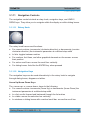
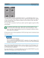
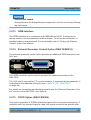
R&S®FSW
Instrument Tour
Front Panel View
3.1.14
TRIGGER INPUT / OUTPUT
The female TRIGGER INPUT connector for external trigger or gate input is used
to control the measurement by means of an external signal. The voltage levels
can range from 0.5 to 3.5 V. The default value is 1.4 V. The typical input impedance is 10 kΩ.
The female BNC TRIGGER INPUT / OUTPUT connector can be used to receive
a second external signal or to provide a signal to another device. The signal is
TTL compatible (0 V / 5 V). You can control the connector usage in the "Trigger"
settings (TRIG key).
The rear panel provides a third TRIGGER INPUT / OUTPUT connector, see
chapter 3.2.10, "TRIGGER 3 INPUT/ OUTPUT", on page 54.
3.1.15
EXT MIXER Connector (optional)
External mixers can be connected at the EXT MIXER LO OUT/IF IN and IF IN
female connectors to increase the available frequency range. This connector is
optional and only available with R&S FSW-B21.
If no external mixers are connected to the R&S FSW, cover the two front connectors LO OUT / IF IN and IF IN with the supplied SMA caps.
3.1.16
RF INPUT 50 Ω
A device under test (DUT) can be connected to the R&S FSW to provide RF input
which is then analyzed. The DUT is connected to the instrument's RF INPUT via
a cable equipped with an appropriate connector.
Risk of instrument damage
Do not overload the input. For maximum allowed values, see the data
sheet. For AC-coupling, a DC input voltage of 50 V must never be exceeded. For DC-coupling, DC voltage must not be applied at the input. In both
cases, noncompliance will destroy the input mixers.
Getting Started 1312.9420.02 ─ 15
49