1
-----
83508
SWEEP OSCILLATOR
.-
© Copyright
HEWLETT· PACKARD COMPANY
1983
1400 FOUNTAIN GROVE PARKWAY. SANTA ROSA. CA. 95404
MANUAL PART NO. 08350·90034
Microfiche Part No. 08350-40035
Printed:
JANUARY 1983
~~~~~~
~---
Local Operation
Mode18350B
-
-
LOCAL OPERATION
INTRODUCTION
This Local Operation handbook provides information on the local use (non HP- IB) of the
8350B Sweep Oscillator with 83500 series Plug-ins. Throughout this handbook are blocks of
example procedures on implementing some of the information. The front panel controls are
divided into function groups. These groups and other information topics are arranged in the
following sequence:
•
GETTING STARTED - Brief example of control usage.
•
INSTRUMENT PRESET - Error codes and preset conditions.
•
DATA ENTRY - Numeric, step, units, and shift keys.
•
FREQUENCY - Mode selection, vernier and offset.
•
FREQUENCY/TIME - Markers and sweep control.
•
SAVEn/RECALLn/ALTn - Storage Registers, Step Up Advance.
•
DISPLAY FUNCTION - Blanking, Modulation, and Sweep Out/In.
•
83500 SERIES PLUG-INS - Power, signal, and crystal markers.
•
USE WITH SPECIFIC MEASUREMENT EQUIPMENT:
HP 8756A Scalar Network Analyzer
HP 8755S Frequency Response Test Set
HP 84l0B Network Analyzer
HP 7010B and other X-Y Recorders
HP 5343A Frequency Counter
•
APPENDIX 1 - Rear panel connector information.
•
APPENDIX 2 - Use of 86200 series Plug-Ins with 1I869A Adapter.
•
APPENDIX 3 - Summary of Sweep Oscillator front panel controls with fold-out front
panel drawing.
GETTING STARTED
NOTE
If a 86200 series RF Plug-in and 11869A Adapter are used,
the Plug-in coding on the adapter must be set properly to get
the correct frequency display.
--
When the 8350B INSTR PRESET key is pressed the front panel of the 8350B is set to the
following pre-determined state: The RF output is swept over the full frequency range of the
Plug-in at the maximum specified leveled output power, minimum sweep time for the RF
Plug-in installed, and the internal square wave amplitude modulation is off.
Model 8350B
Local Operation
Example:
8350B with 83525A 0.01-8.4 GHz Plug-in
To change from the INSTR PRESET state to 4.2 to 6.2 GHz sweep (in START/STOP mode),
0.20 second sweep time, +4.5 dBm output power, 27.8 KHz square wave modulation on
RF output:
1.
Press the [START] key and then rotate the START control clockwise to increase the
start frequency until the display above the START key reads 4.200 GHz
2.
Rotate the STOP control counterclockwise to decrease the STOP frequency to 6.500
GHz.
3.
Press the [TIME] key, then turn the FREQUENCY/TIME control clockwise to increase
the sweep time to 0.2 second (displayed on the FREQUENCY/TIME display).
4.
Press [Lfl MOD] key to activate the internal 27.8 KHz square wave modulation. The
lamp in the center of the key will be on.
5.
Press the [POWER LEVEL] key, then turn the Plug-in POWER control until the display reads +4.5 dBm.
INSTRUMENT PRESET
This condition occurs when the INSTR PRESET key is pressed.
Turning the 8350B on or performing an INSTR PRESET causes an internal self test to
occur. Only after the INSTR PRESET command will the instrument be set to the preset condition. If certain internal errors or failures are detected during the self test or during normal
operation they will be indicated via error codes in the form "Ennn" (where n=O, ... ,9) read
from the left FREQUENCY display. For a complete description of the error code listing see
the Operating and Service Manual Section 8. The error codes are:
EOOI
Plug-in interface failure. Check Plug-in.
E002
Sweep voltage DAC/Marker voltage DAC failure
E003
Tuning voltage DAC/Marker voltage DAC failure
Figure 1. Instrument Preset Key (I of 2)
2
,
I
Local Operation
Model 83S0B
E004
Power supply failure
EOOS
Instrument interface bus failure
E006
Front panel bus failure
E007
E008
E009
EOIO
ROM
ROM
ROM
ROM
failure
failure
failure
failure
EO 11
EOl2
EOl3
EOl4
RAM
RAM
RAM
RAM
failure
failure
failure
failure
EOIS
Microprocessor failure
EOl6
Insufficient cooling. Check air filter and fan.
E030
A SAVEn Command has been attempted when the SAVE-Lock is
engaged.
E050 to E099 Plug-in failure. Refer to appropriate Plug-in manual for troubleshooting
information.
If, after INSTR PRESET, the self test completes without errors the instrument presets to:
SWEEP MODE:
SWEEP TIME:
MARKERS:
START/STOP, over full frequency range of Plug-in
fastest allowable for Plug-in
reset/off
MODULATION:
off
SWEEP TRIGGER/SWEEP:
VERNIER/OFFSET:
0 MHz
DISPLAY BLANKING:
SAVE/RECALL:
INT-TIME
on
All SAVE registers remain unchanged.
All Other Functions:
off
When using 83500 series Plug-ins:
POWER LEVEL:
RF:
maximum specified leveled value
on (Selectable by RF Plug-in configuration switch.)
ALC MODE:
INT
CRYSTAL MARKERS:
All Other Functions:
off (83522A, 83525NB only)
off
Figure 1. Instrument Preset Key (2 of 2)
3
Model 835GB
Local Operation
[MJ
"tooISWlU'OSCIlLAlOOO
'''IOUINC~
10
••.
B.YOO -.
,",~ ...,,,m.:=,,
I
0.011:::.
D··
..· D""u, ~o"
~
00
':JW~""'I'1.UG·'"
)
0._.......
~""I.-
.
rm
O"lJ.I..L...J0N .w'
()
DATA ENTRY
The DATA ENTRY section shown above. contains the numeric keyboard. terminators (i.e..
GHz. seconds. dBm), step size/up/down. backspace and shift keys. This section allows a
specific value to be entered for any Frequency. Time, or power parameter. The entry will
modify the active function (last function selected) and must be terminated with the appropriate GHz/seconds, MHz/milliseconds, or dBm/dB Key. The step up [.] and step DOWN
[.] keys allow the active function to be incremented or decremented. Step size for frequency and Power may be changed to any desired value.
Number/unit keys
These keys are used to enter values of frequency, time or power. Holding a number key
down causes it to repeat.
Q)
Example:
To enter a START frequency of 1.870 GHz:
Press [START] [1] [.] [8] [7] [GHz/s]
or
[START] [1] [8] [7] [0] [MHz/ms]
to enter the equivalent frequency in MHz.
Backspace Key BK SP. Prior to pressing a units key the value entered from the keyboard
may be changed via the BK SP key without effecting the current instrument state. The backspace key allows the user to alter digits already entered. Holding down the Backspace key
causes it to repeat.
Step UP and Step DOWN keys
These keys increment or decrement the active function (including memory registers) by the
STEP SIZE or preset amount. By holding either key down the 8350B will continue to step
Figure 2. Data Entry (1 of 2)
4
0)
Local Operation
Model 8350B
"
therefore eliminating the need for the user to repeatedly press the step keys. The STEP UP
function may be engaged via the remote STEP UP ADVANCE on the rear panel AUX
PROGRAMMING connector. The STEP UP ADVANCE is incremented by supplying contact closure to ground or logical 0 to pin 22.
STEP SIZE
Entering a frequency or power increment to be used with the UP or DOWN key. The STEP
SIZE key is pressed before the quantity is entered. A frequency step that is entered is common for START, STOP, CF, CW, MARKER and MANUAL SWEEP functions. A power
step is used for varying POWER LEVEL. Default values are assigned at instrument preset
for step sizes until new values are entered Note that a step size for SWEEP TIME cannot be
entered and always increments in a 1,2,5 sequence. The step keys affect the last active function. The entered Step Size is not displayed.
Example:
To set a 250 MHz step size:
Press [STEP SIZE] [2] [5] [0] [MHz/ms]
After this, each time the UP or DN key is pressed the active frequency parameter
will change by 250 MHz.
)
SHIFT key (BLUE)
This key is used to activate the functions coded in blue on the front panel and other special
SHIFT functions are also explained on the pull out information card. The lamp in the center of this key is on when the key is active.
Example:
To activate all 5 frequency markers: Press [M1] [M2] [M3] [M4] [M5]
To turn off all 5 frequency markers at once:
Press [SHIFT] [OFF]; this activates the (markers) ALL OFF command.
The SHIFT key is also used to set the HP-IB address. Press [SHIFT] [LCL]; the
FREQUENCY/TIME display will indicate the present HP-IB address number. The address
may be changed to any value between 0 and 30 by using the keyboard to enter a number and
the GHz, MHz or dBm key as a terminator (It does not make any difference which of the
terminator keys is pressed). The 8350B is factory preset for an HP- IB address of 19.
NOTE
Address number 21 is normally reserved for calculator
addressing and HP-IB interface functions and should not be
used.
Figure 2. Data Entry (2 of 2)
5
Model 8350B
Local Operation
ll¥JJ
'JMI'SWU~OSCllLATOIl
,
ID
..
8.'-100 ,
..
(I
0_0
f';~~'Ei"'@]] ffi~
0"
mo.
'0'
0.01l
~881®j
I ~[§jl§
10D
DUAunllT
@ 808 (@
':::0 ::::.
.~"
ON/Off
'0'00 ..... _~
~
.*...,.....
_.
"
0
" B
(§l (8188 ~
~(88G)~
[Q)] (81(8 fGl ~
I
188~ (® (®(®l®J
. 'w""
aHUAU"lUO·".
POWEII_
- I DOG I
.,0
Q :.(®(®(@)
OO·"'~
" " " GEll
BGlEJl
' - Q""~T ..J
[M)
HEWLETT.PACKAAD
flU:OUE"lCY
"''''''Ull
83~T
~
.~o
"--=-- "" - - . J
......
~.~.~l®J
[!i)[!i)I
[§J(§]-
[
'litO
Ale MODE
1
(®S8
INI"UT
'0 ~
' - - - (llT/MTII Ale---J
FREQUENCY
The gray area, shown above, controls the sweep modes and frequency limits.
START/STOP
When either the START or STOP key is pressed the sweep oscillator is put in the START/
STOP mode swept RF output begins at the START frequency and ends at the STOP frequency. The START frequency must be less than or equal to the STOP frequency. The left
FREQUENCY display shows the value of the start frequency. While the right FREQUENCY display shows the value of the stop frequency. Frequencies may be changed in
three ways.
•
Frequency control knob increases frequency.
•
Keyboard data entry - Specific frequency values may be entered for the active frequency mode by Pressing the desired values and units.
•
Step Control Key - THE ACTIVE FREQUENCY FUNCTION can be incremented or
decremented by pressing the appropriate STEP key. The value of the STEP SIZE can
be set to any desired value (see STEP SIZE for setting procedure).
Provides continuous adjustment. Clockwise rotation
0
CF/~F
The CF/ ~F mode allows the swept output frequency range to be read as a center frequency
and a frequency sweep width. The output frequency is swept from CF-~F/2 (start frequency) to CF+~F/2 (stop frequency). When changing between CF/ ~F and START/STOP
modes only the method of display changes. The swept RF output remains the same.
When either CF or ~F is activated the left display shows the center frequency (CF), the right
display shows the delta frequency (~F). Both the CF and ~F can be changed via the
appropriate control knob, number/units keyboard or step keys.
CW
When the CW function is activated the 8350B outputs a constant frequency. The value of the
CW frequency is displayed on the left FREQUENCY display. The CW frequency is always
the same as the center frequency (CF) of the CW/ ~F swept range. The CW frequency value
can be changed using the control knob, data entry keyboard or step keys. In CW mode, the
SWEEP OUT voltage is equal to a percentage of the full band. Pressing [SHIFT] [CW]
enters a "swept" CW mode with the SWEEP OUT being a 0 to 10 volt ramp that results in
the display trace being a flat horizontal line. This is often useful when reading values (e.g.,
dB of attenuation) from a CRT screen when at a CW frequency.
Figure 3. Frequency Controls (1 of 2)
6
0
I
Local Operation
Model 8350B
-
CW Fine/Coarse Control Knob Resolution
CW control knob resolution is coarse when CW mode is activated after an INSTRUMENT
PRESET. To change from coarse control knob resolution, 0.0015% of band/16,384 points, to
fine resolution, 0.00038% of band/262,144 points, press [SHIFT] [ilF]. To return to coarse
control knob resolution press [SHIFT] [CF].
FREQUENCY VERNIER
The effective center frequency of any mode (CW or swept) may be adjusted with high resolution up to +0.05% of the frequency band being used with the vernier. Pressing the
VERNIER key activates the function and sets the left FREQUENCY display to read the
vernier value in MHz.
1.
"~O"
2.
Frequency vernier can be set by the control knob, Data Entry keyboard, or step keys.
3.
The displayed vernier adjustment can be up to +0.05% of the frequency band being
swept When in a sub-band of a multiband Plug-in (for example, the 0.01-2 GHz band
of the 83525A .01-8.4 GHz Plug-in) the adjustment range will be ±0.05% of the subband. This feature allows for better frequency resolution than would otherwise be
possible with the vernier when using a multiband Plug-in.
4.
The vernier adds its value to the appropriate frequency parameter and then resets the
vernier to zero when the adjustment exceeds +0.05% for continuous adjustment
5.
ZEROING VERNIER. To set the vernier to zero, press [VERNIER] [0] [MHZ/ms]
and the"~O" lamp will turn off.
light is on whenever a frequency vernier or frequency offset is present in any
mode. After setting vernier, to return to the previous mode, press the appropriate key
(e.g., START, CF, etc.) and the display will return to reading the appropriate frequencies and the "~ 0" lamp will be lit
FREQUENCY OFFSET
The frequency offset feature allows the CW frequency and/or the effective center frequency
of the swept range to be shifted by any amount up to the full range of the Plug-in.
1.
To enter an offset press [SHIFT] [VERNIER] and enter the offset by either the left
FREQUENCY control or data keyboard. The amount of offset (in GHz or MHz) will
be shown in the left FREQUENCY display and the "~ 0" lamp will be lit
2.
To exit the displayed offset mode press the appropriate mode key (i.e., START, CW,
etc.). The sweep limits displayed will appear to be unchanged, however the "~ 0" lamp
will be on indicating the offset is present and the actual RF output frequency will be
shifted.
3.
To display or adjust the frequency offset press [SHIFT] [VERNIER]. To zero the offset
press [SHIFT] [VERNIER] [0] [MHz].
OVER RANGE
The 8350B will permit frequency sweeps beyond the specified range of the Plug-in by +2.0%
of the Plug-in bandwidth. However, Plug-in performance in the overrange condition is
unspecified.
As a warning of the frequency overrange condition the GHz or MHz annunicator will
flicker in the appropriate function display.
Figure 3. Frequency Controls (2 of 2)
7
Model 8350B
Local Operation
[I@
n~o.sWnpOSCllU.TO"
,",oo,,,,m.:..~
0.011 :::
FREQUENCY
...
10
(Wj'''~
C
....
().o
OF.nT~
8.'i00 '"
0 '°'0
" "
" " " GlB ~8~
BlGG
~
'0''0''8 ID
lEB~ ~m8
r'·..·"·,·"'. .
I
.'" ll!I:J.. ';)' t®J~mm
I
l1'IID
IlEWlfTT. P,",CIIA"O
Dom
... .. -
-~'
[@ill)
,
......RUIl
10.0
UNCOILIO
~888~
(§)[§) .0_
[2J) 00(8~
WEEP
ONion
__OM,
0
" B
080 ~
m8~ ~@~@j) .~
0'_'"<)'''
POWER--
I
@ 80lGll®
IJU,AR,PlUO·'"
[
GJ]~'
~
.~.
""""':=:'-IIF-----J
.IIEO
......
~.~,~~
@]@]
~
I
l®'8°~
'N/'IlT
'0'
L...-
t@
UT/MU " l C - '
FREQUENCY/TIME
The FREQUENCY/TIME portion of the front panel shown above enables the control of the
SWEEP TRIGGER modes, the SWEEP modes and the frequency markers.
SWEEP
The 8350B SWEEP Mode select keys provide three ways to control the frequency sweep;
TIME, MANUAL, and EXTERNAL sweep, described below.
TIME. When the TIME key is pressed the output is swept at the user-specified or default
rate. If the time key is lit but the display reads GHz/MHz or is blank, press the TIME key
again and the display will read seconds. The mainframe can allow sweep times from 100
seconds to 0.01 second although the minimum sweep time is dependent on the Plug-in being
used and the bandwidth being swept
When display reads seconds, sweep time can be adjusted with the control knob or number/
units keyboard. The step keys can be used to adjust the sweep time in a 1-2-5 sequence.
MANUAL SWEEP{MAN). FREQUENCY/TIME display will read GHz/MHz. By using
the FREQUENCY/TIME control, step keys or number/units keyboard, it is possible to
manually sweep the frequency range with the display indicating the present output
frequency.
EXTERNAL SWEEP{ EXT). The 8350B can be swept via an external voltage. Apply 0 to 10
volts into the sweep output/input (use BNC connector on front or rear panel) with OV input
corresponding to the lower freq uency limit of the sweep range and lOY corresponding to the
upper limit. DC sweep input voltages will cause CW frequency outputs. Markers and blanking outputs are disabled when in external sweep mode.
SWEEP TRIGGER
Controls when the sweep will begin in the timed sweep mode. The sweep light, SWP, is lit
when the sweep is occurring.
INT.
LINE.
Sweep triggered internally, free running.
Sweep triggered by power line frequency.
Figure 4. Frequency/Time Controls (1 of 3)
8
c~
Model 8350B
"
Local Operation
EXT. The sweep can be triggered externally by applying a positive going signal from 0 to 2
volts minimum, +20volts maximum. The trigger signal must be wider than 0.5 microsecond
at less than a I MHz repetition rate.
SINGLE. This key selects single sweep mode and aborts present sweep when first pressed.
Subsequent keying will trigger or abort single sweeps at current sweep time.
MARKERS
Any or all of the five markers (MI through M5) may be enabled by pressing the marker key
corresponding to the marker desired. When a marker is activated it is set to its last active frequency unless INSTRUMENT PRESET has been activated in which case the marker will
be set to center of the present sweep. A marker can be in one of three states:
•
ACTIVE - Lamp in center of key flashing.
•
ON - Lamp on.
•
OFF - Lamp off
The five mainframe markers are available in two forms, Intensity and Amplitude.
Intensity markers are active any time a marker is selected. These markers are available at
the Positive Z-axis output (rear panel BNC) and appears as intensified dots on a display.
Amplitude markers are only on when the AMPTD MKR key has been pressed. Amplitude
marker circuitry is internal to the 8350B mainframe and RF Plug-ins and causes dips in the
RF output power at the selected marker frequencies.
Only one marker at a time, the "active" marker, can have its value altered. Pressing any
marker key makes that marker "active".
•
When a marker is active the keyboard, FREQUENCY/TIME control knob, step keys,
or DATA ENTRY Keyboard can be used to modify its value. The value of the active
marker in G Hz/MHz is displayed.
•
By pressing OFF, the active marker only will be turned off. If multiple markers are on,
the remaining lamps will remain lit although the display will go blank.
•
A marker may be initially activated or returned to active state by pressing the corresponding marker key.
•
All markers may be turned off simultaneously by pressing
[SHIFT] [OFF].
Example:
To activate Marker "3":
Press [M3]. (Note M3 lamp flashing other lamps off)
To activate Marker "5":
Press:[M5]. (Note M5 lamp flashing, M3 lamp on and other lamps off)
Figure 4. Frequency/Time Controls (2 of 3)
9
•
Local Operation
Model 8350B
MKR (Marker) SWEEP. In this mode the RF output is swept between markers Ml and
M2. The lamp over the key will be on. Marker 1 must be less than or equal to Marker 2 in
frequency (if MI is greater than M2 the values of MI and M2 are permanently
interchanged). By varying the active marker (l or 2) or by turning the START/STOP controls the sweep limits can be altered. When both MI and M2 are not on, the sweep occurs
between the most recent values of MI and M2. To exit this mode press
[MKR SWEEP] and the lamp over the key will go out. Pressing [SHIFT] [MKR SWEEP]
causes the values of MI and M2 to become the START/STOP frequency values
permanently.
Q
MARKER-TO-CENTER FREQUENCY (MKR--+CF). When this key is pressed the frequency
of the active marker becomes the center frequency of the swept output. The frequency span
remains unchanged if it is within the frequency limits of the Plug-in. If the original frequency
span exceeds the Plug-in limits frequency span will be reduced to retain symmetry.
MKR d. This function allows the frequency difference between any markers to be displayed
and the trace between them intensified (if intensity markers are selected).
1.
Press [SHIFT] [M1] the display shows the frequency difference between the currently
active marker and the one that was previously active.
2.
The FREQUENCY/TIME control, DATA ENTRY keyboard, or step keys can change the
active marker value.
3.
To exit MKR d mode press [OFF].
Example:
I
1.
Press [M4] and set frequency via DATA ENTRY or Control Knob to 2 GHz.
2.
Press [M2] and set frequency via DATA ENTRY or Control Knob to 2.4 GHz.
3.
Press [SHIFT] [MKR d] (Note Frequency/Time display reads difference between
marker 4 and marker 2, 400 MHz).
Q
Figure 4. Frequency/Time Controls (3 of 3)
10
Local Operation
Model 8350B
[:Ml
n50~$wtE"OSCIH"'TOl'I
IIfWLlTT, ..ACKAIIO
."
8.'"100 ."
O.Oil
.... ~
~
0_0
.... o,,.u ....
"0" "'0' EJ ( § ffi ~
r'·"·"M'·"'""~1
,.. m,· 'c' ~G8@]
,
·~:.,O
0
" " " GBJ
" "
BJGJGl
o
....
fllfOUEIlCYfTlME
'lI~out:"'CY
10
~~~
GG8
(IfIl
I - DDGJ- I
..... lIlIffl
10.0
":::'
..
::.::~ .~
~,
18~l® I ~~88 .~
r®]~T
~ '~~
"--=-- II' - - - - - - J
"'H,
IDID M~'
§[§)
I
'"Ell
~~,~(@
0
" BMO.
(§) ~88~
@ GOG@)]
-"
"II'"O'"D
O.... ENfll.
~ GlGJ8~
~ GJ(8)GJ~
U5~U~' ,.::~:....::.:..::.:.
ALCMODE
]
88~
INPUT
';"~
I..-
UT/MU .flu::-J
SAVEn/RECALLn/ALTn
SAVEn/RECALLn
o
The 8350B is equipped with memory registers which allow up to nine complete front panel
settings (frequency range, markers, power level, etc.) to be stored and later recalled Instrument settings are stored in memory locations 1 through 9 by pressing [SAVEn] and 1, ..., or
9. To recall a stored instrument setting press [RECALLn] and 1, ..., or 9. The STEP keys
may be used to step through the stored registers. The instrument settings stored in memory
may be recalled remotely in sequence by using the Step Up Advance on pin 22 of the Auxiliary Program connector on the rear panel of the 8350B. A contact closure to ground or
logic 0 is used to implement this function.
SAVE REGISTER LOCK:
All Save Registers may be write-protected (locked) by pressing [SHIFT] [SAVEn]. This command makes it impossible to change the contents of any register until it is unlocked by pressing [SHIFT] [RECALLn]. Since the 8350B memory is non-volatile the contents of the Save
Registers and the locked/unlocked status are retained even with Line power off. If a SAVEn
command is attempted after SAVE LOCK is engaged an Error 30 (E030) is displayed.
ALTn
ALTn causes the 8350B to alternate between the current instrument state and the setting
stored in memory location n (where n=I, ... ,9) on sucessive sweeps. When the 8350B is in
this mode the lamp will be on and the SAVE and RECALL keys disabled. To exit from the
ALTn mode press the key again, the lamp will turn off and the SAVE/RECALL keys will
become operational. When using the 8350B with an HP Swept Amplitude Analyzer, channel
1 displays the current instrument state and channel 2 displays the stored setting (provided
the 8350B ALT SWP INTERFACE cable is connected to the analyzer).
Figure 5. Save n, Recall n, and ALT n Keys
11
Local Operation
Model 8350B
rr~
.~
•• ~ .....l,IG-,..
"_1. OM.
I'OWlII_
DISPLAY FUNCTIONS FOR ANALYZER INTERFACE
AMPT MKR DSPL BLANK RF BLANK (Function in effect when lamp in center of key is
lit)
DSPL BLANK ON/OFF.
NEG Z BLANK outputs.
RF BLANK ON/OFF.
Blanks the display during the retrace via the POS Z BLANK or
Blanks (turns off) the RF power during the retrace.
Lfl MOD ON/OFF. Activates the internal 27.8 KHz square wave amplitude modulation
of the RF output. This feature makes the 8350B directly compatible with the HP 8756 and
the HP 8755 Scalar Network Analyzers. The 8350B may be modified via an internal jumper
to provide 1000 Hz square wave amplitude modulation for instruments like the HP 415E
SWR Meter (refer to the Operating and Service Manual Section 5).
SWP (Sweep) OUTPUT/SWP (Sweep) INPUT (BNC connection).
SWP (Sweep) OUTPUT. Supplies a 0 to 10 Volt signal when 8350B is in MAN or TIME
sweep mode. OV output is at the start frequency of sweep. 10V output is at the stop frequency
of sweep. In CW mode the output is a dc voltage proportional to the percent of the band.
This can be used to drive the X-axis on a CRT or X- Y recorder.
SWP (Sweep) INPUT. Used when in EXT sweep mode. Supplying a dc voltage will tune the
RF where 0 volts tunes to the lower frequency of the set sweep and 10 volts tunes to the
upper frequency. The input can be a ramp for a swept output or DC for a CW frequency.The
display and RF blanking must be off when externally sweeping.
DISPLAY FUNCTIONS FOR FREQUENCY MULTIPLIER OR UP-CONVERTER
INTERFACE
Two SHIFT functions located in the Frequency section of the front panel allow the actual
RF output frequencies to be displayed when a frequency multiplier or frequency upconverter is used.
DISPLAY MULTIPLIER. This function is activated by pressing [SHIFT] [START] [n]
[GHz]. The possible values for "n"" range from 0 to +99 allowing the appropriate integer
multiplier to be entered. This integer (n) multiplier (typically 2 or 3) does not affect the RF
output of the 8350B but simply allows the Frequency LED displays to automatically show
the final RF output when a frequency multiplier is used.
DISPLAY OFFSET. This function is activated by pressing [SHIFT] [STOP] [n] [GHz].
The possible values for "n"" range from 0 to +999 G Hz enabling an appropriate Frequency
LED display offset to be entered. This display offset does not affect the 8350B RF output but
only allows the Frequency LED displays to automatically show the final RF output when a
frequency up-converter is used.
Figure 6. Display Function Keys
12
Local Operation
Model 8350B
[M)
"1l1..... O'\.UQ·, ..
0'-••
0"'
POWIJI_
83500 SERIES PLUG-IN
Power Control
POWER LEVEL. When the POWER LEVEL key is pressed, the Plug-in display indicates
the RF output power. The output power may be varied using the POWER control knob,
keyboard or step keys. Note that the internal leveling must be on and the unleveled light out
for calibrated output power. See Plug-in manual for Plug-in calibrated range. ALC dynamic
range depends on Plug-in installed and its options, if any.
SLOPE. Compensates for high frequency power losses in external RF cables by increasing
power at higher frequencies. This compensation provides a flat RF signal output at the end
of a cable or test set. Press [SLOPE] and the display will indicate dB/GHz of compensation
desired. Use the POWER control knob, keyboard or step keys to enter the amount of slope.
Press [SLOPE] again to remove all compensation.
POWER SWEEP. This function enables the output power to be swept up. The maximum
calibrated power sweep range depends on Plug-in installed. Note that when using Plug-ins
withe Option 002 Step Attenuator, the power cannot be swept across the internal attenuator
switch points. The procedure for performing a power sweep is:
1.
After selecting the output frequency (sweep range or "swept" CW mode) use the
POWER LEVEL key to set the starting value for the power sweep.
2.
Press the [POWER SWEEP] key, the display will now read the dB/SWEEP. By using
the POWER control knob, keyboard or step keys set the desired sweep range. The
original power setting becomes the lower limit of the Power Sweep. The lower limit plus
the entered sweep value is the upper sweep limit. Press the [POWER SWEEP] key
again to turn the power sweep off.
)
Figure 7. Plug-in Controls (j of 2)
13
Model 8350B
Local Operation
Signal Control
RF ON/OFF.
Turns the RF power on and off.
CW FILTER ON/OFF. When on, this filters the internal oscillator's tuning voltage to provide a more stable CW output. During swept operation this filter is always disabled.
ALC (Automatic Level Control) Mode:
INT, EXT, MTR
INT. Provides internal leveling of output power at the output connector. The 83500 series
Plug-in must be on INT leveling for calibrated output power.
EXT. This setting is used when leveling with an external crystal/diode detector. The front
panel EXT ALC input accepts negative voltages in the -25 to -250 millivolt range
(typically).
MTR.
Used when leveling output power with an HP 432NB/C Power Meter.
CAL. Adjusts the ALC gain so the display can be calibrated by an external power meter
or detector.
CRYSTAL MARKERS (83522A, 83525A/B Plug-ins only)
50, 10, and 1 MHz crystal frequency marker combs are available. The 50 and 10 MHz are
available in band 0 while the I MHz markers are available under I G Hz.
AMPTD/INTENS. The markers can be set to be amplitude dips (on the RF output) and/or
intensified spots (on the Z-axis of the CRT) or both. They are independent of the mainframe
markers.
EXT (External Marker). An external frequency marker can be input through the rear
panel of the Plug-in. The marker appears when the RF output frequency equals the marker
frequency. The external marker input power should be between -10 dBm and -10 dBm.
MKR Lamp. When the 8350B is in CW or manual/external sweep mode the MKR Lamp
will light when the CW frequency is at a marker frequency. Useful when an accurate CW
frequency reference is desired and to calibrate Plug-ins.
RF OUTPUT CONNECTOR
Type N female. The 83570A 18 to 26.5 GHz Plug-in is equipped with a WR-42 waveguide
output connector.
Q
Figure 7. Plug-in Controls (2 of 2)
14
Local Operation
Model 8350B
~-HfWUiTf
@:
@):
8
:@
ono(;)
:@)
OCOB
:~,::
G·
G]:
PACI<.ARQ
B
·8
:0
OOO~
G0800§
B C::;:;':l(=
G;).
=
.
~
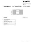
Figure 8.
8756A Scalar Network Analyzer
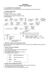
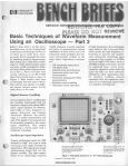
INTERFACING THE 83508 WITH SPECIFIC MEASUREMENT EQUIPMENT
8756A SCALAR NETWORK ANALYZER
The 8756A is used for scalar transmission and reflection measurements. with 60 dB of
dynamic range for ratio measurements. and absolute power measurement from -50 dBm to
+10 dBm.
The 8350B has the following features designed for use with the 8756A Scalar Network
Analyzer.
RF Square-wave Modulation. By engaging the LJl MOD key an internally generated
squarewave modulation of the RF output is available thus eliminating the need for external
modulating equipment. A jumper internal to the 8350B enables the square wave modulation
frequency to be changed to I KHz (see section 5 of the Operating and Service manual for
details).
)
Alternate Sweep Function. The ALTn function of the 8350B allows two different frequency and power settings to be swept on successive sweeps. The front panel setting and the
setting stored in a memory register location n (n= L ....9) can be selected for alternate
sweeps. See Figure 9 for a sweep display of the ALTn function when used with a bandpass
response at different resolutions and offsets.
IS
•
Local Operation
Model 8350B
-
I
f-t=l3
i\
\
......
.....
4 GHz
'-!
6 GHz
--
0.25 dB/DIV
\
,
6 GHz
4 GHz
Figure 9.
10dB/DIV
Alternate Sweep Function Display
Some other features enhancing the convenience and versatility of the 8756A are:
Marker~. The MKR ~ function reduces the trace intensity between the Active and the
previously Active Markers.
Power Sweep. The RF output power may be ramped up when the sweeper is in the swept
or'"swepC CW mode by using the POWER SWEEP function. See Figure 10 for a gain compression display using power sweep.
Save and Recall.
instru men t setti ngs.
This function allows the storage and recall of nIne complete
a
18
17
AMPLIFIER
GAIN=15dB
16
I
15
GAIN
(dB)
.........
14
'\.
\
13
POWER
SWEEP
12
11
10
2
4
6
8
10 12 14 16 18 20
POWER IN (dBm)
Figure 10.
Gain Compression Display
Figure II outlines the general procedure used in making a scalar transmission and reflection measurement. The 116920 Dual-Directional Coupler is used in the example but if an
11666A Reflectometer Bridge. a 85020NB. or a 85021 NB Directional Bridge is available. it
may be used instead of the Coupler and two detectors.
For more information and additional features of the 8756A with the 8350B. refer to the
Operating Section of the 8756A Operating and Service Manual.
16
c
Model 8350B
Local Operation
Example:
1.
Connect the equipment as shown in the diagram below. Initially. the 8350B should be
set by pressing [PRESET] on the 8756A. The sweep time will be set to 150 ms. the 8350B
internal square wave modulation and the 8350B INSTR PRESET will he activated.
HP·18
r------------------------,
83508 SWEEP
OSCILLATOR
_ _
08. 0
00669
,·DODO
.0
eEll:)
E1E10
83500
SERIES PLUG·IN
8756A
SYSTEM
INTERFACE
8756A SCALAR
NETWORK ANALYZER
OOOJ
STOP SWEEP
DODO []
8gggg
POS Z BLANK
80000
SWP OUT
-
RF OUTPUT
==
0
0
0
0
0
0
0
0
:CJ
0
:0
0
0
:0
000000
0
·0
:0
c:::JDDD
0
0
.
~
0000
0000
0000
~
,
~
==~
A
8
R
11664A
O.U.T.
INCIOENT
~
I
'-,'-r----..,....,.-'
116920 COAXIAL
OUAL OIRECTIONAL COUPLER
11664A
Notes on connections:
•
Either the front or rear panel SWEEP OUT/IN may be used.
•
When in ALTn mode both channels I and 2 (on 8756A) must be on and
receiving inputs.
2.
Turn off channel I on the 8756A by pressing [SHIFT] [MEAS RATIO]. Set the 8350B
controls as desired. On channel 2 set the function. dB/DIY and Offset desired for viewing the current sweep setting.
3.
Set the 8350B controls as desired then store the current 8350B sweep setting in any
available memory location. Then turn ofT channel 2 of the 8756A by pressing the
[SHIFT] [MEAS RATIO] pushbuttons.
4.
On Channel I of the 8756A. set the function. dB/DIY and Offset as desired. Set 8350B
controls as desired.
5.
Turn on channel 2. Press [ALTn] [n] and the 8350B will alternate between the two settings on successive sweeps.
I
Channel I now displays the response due to the current front panel setting while channel 2
displays the response to the setting stored in memory location n. The front panel controls of
the 8350B are enabled and the current sweep setting may be altered if necessary.
Figure 11.
Typical Test Setup Using 8756A
17
Local Operation
Model 8350B
..
I
....-- -
~.i ... 0 8.0 ~.o.:.J
=1
DO
-
•
..
• 0
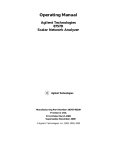
Figure 12.
.....
-
--
0
.
Frequency Response Test Set
8755S FREQUENCY RESPONSE TEST SET
The 8755S consist of:
•
8755C Swept Amplitude Analyzer
•
182T Oscilloscope
•
I I664A Detectors (3 each)
•
8750A Storage-Normalizer
The 8755S is used for scalar transmission and reflection measurements requiring up to 60
dB of dynamic range and for absolute power measurement from -50 dBm to + 10 dBm.
The 8350B has the following features designed specifically for use with the 8755S Frequency
Response Test Set:
RF Square-wave Modulation. By engaging the Lfl MOD key an internally generated
squarewave modulation of the RF output is available thus eliminating the need for external
modulating equipment. A jumper internal to the 8350B enables the square wave modulation
frequency to be changed to I KHz (see section 5 of the Operating and Service manual for
details).
The ALTn function of the 8350B allows two different frequency and power settings to be swept on successive sweeps. The front panel setting and the
setting stored in a memory register location n (n=1. ... ,9) can be selected for alternate
sweeps. The Alternate Sweep Function will not work properly with the 8755A or 8755B. See
Figure 13 for a sweep display of the ALTn function when used with a bandpass response at
different resolutions and offsets.
Alternate Sweep Function.
18
Model 8350B
Local Operation
o
~
-
......
4 GHz
6 GHz
~~i\
'-
'"
-
~
0.25 dB/DIV
\
\
4 GHz
Figure 13.
10 dB/DIV
6 GHz
Alternate Sweep Function Display
Some other features enhancing the convenience and versatility of the 8755S are:
Marker~.
The MKR ~ function increases trace intensity between the Active and the previously Active markers. The 8750A Storage-Normalizer will need to be in BYPASS mode to
view Z-axis modulation on the oscilloscope.
Power Sweep. The RF output power may be ramped up when the sweeper is in the swept
or "swept" CW mode by using the POWER SWEEP function. See Figure 14 for a gain compression display using power sweep.
Save and Recall.
This function allows the storage and recall of nine complete
instrument settings.
0
18
17
M~PL\FIER
16
GAIN=15dB
,
,
15
GAIN
(dB)
-........:
\.
14
\
13
POWER
SWEEP
12
11
10
2 -4
6
8
10 12 14 16 18 20
POWER IN (dBm)
Figure 14.
Gain Compression Display
Figure 15 outlines the general procedure used in making a scalar transmission and reflection measurement The 11692D Dual-Directional Coupler is used in the example but if an
11666A Reflectometer Bridge is available it may be used instead of the Coupler and two
detectors (8755S Option 002).
To keep the following procedure brief the 8750A will not be used (switched to BYPASS) in
the procedure. The following anomalies exist when using the 8750A with the 8350B Sweep
Oscillator:
(0
•
The 8350B DISPL BLANK must be engaged to ensure triggering 8750A updating.
•
Intensity markers are changed to amplitude markers. In MKR ~ mode they appear as a
level shift over the MKR ~ range.
19
Local Operation
•
Model 8350B
If an 8755 channel
CRn·
IS
switched off the trace goes to the reference line (bottom of
Example:
1.
Connect the equipment as shown in the diagram below. Initially, the 8350B should be
set by pressing [INSTR PRESET] [ LJl MOD] (Set to 27.8 KHz) which will set the front
panel instrument state and activate the internal square wave modulation.
83508 SWEEP
OSCILLATOR
182T
OSCILLOSCOPE
PDS Z BLANK
AUX C
AUX D
8755C SWEPT
AMPLlTUOE ANALYZER
11664A
B
O.U.T.
ALT
SWP
INTERFACE
INCIDENT
I:1
~
....,;.1.,.----
11116920 COAXIAL
-J
---,-,.1 OUAL OIRECTIONAL COUPLER
l
lJ
INPUT
REFLECTED
11664A
Notes on connections:
•
Either the front or rear panel SWEEP OUT/IN may be used.
•
When in ALTn mode both channels I and 2 (on 8755C) must be on and
receiving inputs.
2.
Turn off channel I on the 8755C by releasing the display pushbutton. Set the 8350B
controls as desired and set [ LJl MODI on. On channel 2 set the function, dB/DIV and
Offset desired for viewing the current sweep setting.
3.
Set the 8350B controls as desired then store the current 8350B sweep setting in any
available memory location. Then turn off channel 2 by releasing its display
pushbuttons.
4.
Turn on Channel I of the 8755C and set the function, dB/DIV and Offset as desired.
Set 8350B controls as desired.
5.
Turn on Channel 2. Press [ALTn] [n] and the 8350B will alternate between the two settings on successive sweeps.
Channel I now displays the response due to the current front panel setting while channel 2
displays the response to the setting stored in memory location n. The front panel controls of
the 8350B are enabled and the current sweep setting may be altered if necessary.
Figure 15.
20
Typical Test Setup Using 8755S
Model 8350B
Local Operation
Figure 16. Frequency Response Test Set
84108 NETWORK ANALYZER
The 8350B is compatible with the 8410B Network Analyzer systems and accessories. The
Source Control Cable (HP PIN 08410-60146) synchronizes the two instruments to provide
continuous multi-octave coaxial magnitude and phase measurement capability from 110
MHz to 18 GHz with 65 dB dynamic range. The frequency markers can be displayed in
polar format as intensity dots (Z-axis). Frequency markers derived from crystal oscillators
allow frequency measurements to be made with an accuracy of five parts per million.
,
,
i
10
I
l
Waveguide measurements between 18 and 26.5 GHz can be made with the K8747A
Reflection/Transmission Test Unit which is designed for use with the 841OB. This test system utilizes two 8350B Sweep Oscillators and 83570A 18 to 26.5 GHz RF Plug-ins. One
sweeper is used as a local oscillator while the second is used to sweep the desired
frequency range.
See Figure 17 for an example measurement set up using the 8410B with a single 8350B and
83500 series Plug-in.
The 8410B FREQ RANGE should be set to AUTO. In addition, the sweep time on the 8350B
should be slow enough and/or sweep range narrow enough to insure phase locking over
21
e_n_t_ir_e_s_w_e_e_p_ra_n_g_e_.- - - - - - - - - - - - - - - - - - - -
Model 8350B
Local Operation
8412A
84108
PHASE-MAGNITUDE
NETWORK ANALYZER
DISPLAY
83508 SWEEP
OSCILLATOR
Z·AXIS
POSZ
BLANK
__
83500
SERIES PLUG-IN
ClCl
I f-ooill-:-B'"""LA""'NK,.,....----.--"""'N""'E"::""GZ::--O=B'"""LA"'"N:-:4
K ~I P.": .0. . 0
SWP IN
SOURCE
CONTROL
SWP IN/OUi
@. ~
PROGRAMMING
CONNECTOR
RF OUTPUT
lVIGHz
D.U.T.
RETURN
B411A INPUT
8418A
8414A
AUXILIARY POWER SUPPLY POLAR DISPLAY
0: "'"""'
BLANKING
@- • •
@ • ~
.111--------'
8743A
REF LECTIO NIT RANSM ISSION
TEST SET
I
UNKNOWN
Figure 17.
8350B Connections to 8410
Notes on connections:
22
•
FREQ REF output of the 83500 or 86200 series Plug-ins provides a I-volt-per-G Hz output so that the 841 OB may synchronize with the sweep.
•
The 8410B display units (8412A 8414A) require that the NEG Z BLANK from the
8350B be used as the blanking signal.
•
pas Z BLANK (from the 8350B) line contain the Z-axis markers. This line connects to
the MARKERS input on the 8414A Polar Display and to the Z AXIS input on the
8412A Phase-Magnitude Display.
•
SWEEP OUT/IN outputs a 0 to + 10 volt signal in proportion to the swept or CW frequency output. OV corresponds to the lower frequency sweep limit; + IOV to the upper.
Swept RF output causes a ramp voltage out; CW output causes a dc voltage out.This
connection is necessary only when using 8412A Phase-Magnitude Display.
•
8350B/8410B SOURCE CONTROL CABLE. Provides "handshake" lines for synchronization between 8350B and 8410B (HP Part No. 08410-60146).
r
I
Local Operation
Model 8350B
x-v
RECORDERS
The 8350B is equipped with outputs for controlling X-Y analog recorders.
Some of the HP X- Y recorders that may be used with the 8350B are:
7010B/7015B
7035B
7004B/7034A
7044/7045/7046/7047
The available/required signals for proper operation with an X- Y recorder are:
X INPUT - Typically SWEEP IN/OUT. Supplied by BNC connector on front or
rear panel.
Y INPUT - Y axis voltage. On 8755S Frequency Response Test Set this would be AUX
A for channell or AUX B for channel 2. For 8410B systems, the 8412A display provides
amplitude and phase outputs.
PEN LIFT - Signal line for controlling remote pen up/down. Pen up is open contact
or +5 volts. Pen down (current sink) is contact closure to ground or 0 volt Supplied by
BNC connector on rear panel or pin 10 on 8350B Auxiliary Program Connector.
- ..
RECORDER (SERVO) MUTE - 7044/7045/7047 only. Control line that mutes the
power to the recorder servos for 100 ms at bandswitch (when using multi-band Plugins) or designated points. Pin lion the 8350B Auxiliary Program Connector.
PEN LIFT REQUEST - Allows a pen lift to be initiated by remote control independent of the present pen lift status. Pin 3 on the 8350B Auxiliary Program Connector.
INVERSE PEN LIFT - Inverse function of Pen Lift pin 23 on 8350B Auxiliary Program Connector.
The pen lift control line is assigned to a pin on the Remote Control connector of the X- Y
recorder. For a complete pin assignment listing refer to the Operating Manual for the particular X-Y recorder being used.
Pen lift pin location on X-Y recorders:
Recorder
Pen Lift Pin No.
701OB/7015B
7035B
7004B/7034A
7044N45N47 A
7046A
3
18
18
I
34
23
Model 835GB
Local Operation
~
5343-' IlIICAOWA'IE fREOUENCY COUNTER
~"I
.. ~tf'·""C"""o
Ig
---
5 Y 2 .5
-_.-
-
.... -
-"'-
~~:fGJI.(:J
o 8tGJ
Don
r:-, n n
I-) 8lG5 D n n
"", D·~ n r-I n a
Figure 18,
5343A Microwave Frequency Counter
5343A FREQUENCY COUNTER
The 5343A Microwave Frequency Counter can be used with the 835GB to measure frequencies in swept mode in addition to normal CW frequency measurements.
During swept operation the 5343A will stop the 8350B sweep and count a selected frequency
parameter such as the START frequency. STOP frequency or any frequency markers in the
sweep range. To accomplish this, the 8350B and 5343A communicate via two signal lines
(Counter Trigger. Stop Sweep on the 8350B and Sweep Interface A and B on the 5343A) that
enable the 8350B to externally trigger the 5343A and then allow the 5343A to stop the sweep
long enough to gate and count the selected frequency parameter.
See Figure 19 for the test set up,
Measuring CW frequencies
When measuring CW frequencies the CNTR TRIG and STOP SWEEP connections are not
necessary. The 5343A should be in the AUTO mode and the internal square wave modulation on the 8350B must be off
Auxiliary Output
The auxiliary output of an RF Plug-in (if available) may be used with the 5343A When
using the auxiliary output of a multi-band Plug-in such as the 83592A (0.01-20 GHz) the frequency multiplier feature of the 5343A may be used so that the proper RF frequency is
displayed.
24
Model 8350B
Local Operation
83508 SWEEP
OSCILLATOR
- -
g66606 "/:JC;;f:J
•• 00
CJO
EH:1D
008
§ gggg
8
000
5343A MICROWAVE
FREOUENCY CONVERTER
83500
SERIES PLUG-IN
ci 1111
. g6
G l:I
0000
CNTR TRIG
SWP INTFC A
STOP SWEEP
SWP INTFC B
~~
':':.~. II-------~~
INPUT
RF
OUTPUT
RF OUT
OUTPUT
INPUT
1
I
COUPLEO
L...--------f~"tlL..-~=----------J
OIRECTIONAL COUPLER
Figure 19.
5343A Test Setup
Notes on connections:
<D
•
A power splitter or directional coupler may be used as long as the input to the 5343A
does not exceed +7 dBm or go below the minimum sensitivity.
•
CNTR TRIG (Counter Trigger): Output for controlling the HP 5343A Microwave Frequency Counter. This allows a frequency count of the selected marker, START or
STOP frequency of the present sweep. Connects to the SWP INTFC A (sweep interface,
on the rear panel of the 5343A) to externally trigger the counter.
•
STOP SWEEP: Input for stopping the progress of the forward sweep. When connected
to the SWP INTFC B (sweep interface, on the rear panel of the 5343A) the 5343A stops
the sweep long enough for the counter to gate and measure the selected frequency
marker, START or STOP frequency. If the internal modulation on the 8350B is on, it is
momentarily disabled so that the counter may measure the frequency.
To measure a START. STOP, or marker frequency during a sweep:
5343A: Set to AUTO, SWP M and set desired frequency resolution. Set the rear panel
ACQ TIME switch to MED.
8350B: Select the frequency parameter to be measured by pressing the appropriate key.
START. STOP. or any marker Mn (where n=1, .....5) and then press [SHIFT] [M2]
If the sweep setting is changed or it is desired to exit this mode. disable the 5343A by pressing [SHIFT] [M3] on the 8350B front panel.
Example:
To measure the START frequency.
c
1.
Connect equipment as shown in Figure 19. Set the 5343A to AUTO, SWP M and set
desired frequency resolution.
2.
Press the 8350B [INSTR PRESET] [START] [SHIFT] [M2] keys. The 5343A will temporarily stop the sweep. measure the frequency and display it at the desired
resolution.
25
.
Local Operation
Model 8350B
NOTE
Improve Frequency Accuracy and Stability With HP 5344A
Source Synchronizer.
The 8350B can be used with the HP 5343A Microwave Frequency Counter and the HP
5344A Source Synchronizer to achieve 1 KHz frequency accuracy with 1Hz frequency
resolution in a CW mode. Analog swept frequency accuracy can also be improved by the
wideband Lock-and-Roll techniques and narrowband (40 MHz) phase-lock sweep
capabilities controlled by the 5344A Source Synchronizer. Added stability is possible by
phase-locking the 8350B RF output to the 10 MHz time-base crystal of the 5343A Counter.
For more information see a HP 5344S Source Synchronizer data sheet or Operating and
Service Manual.
APPENDIX 1
REAR PANEL CONNECTIONS.
For a diagram of the rear panel see Figure 20.
POS Z BLANK Positive Z axis blanking signal. Supplies a rectangular pulse of approximately +5V into 2500 ohms during the retrace and bandswitch points of the RF output.
Also supplies a -4 V (-8 volts for active marker) pulse when the RF is coincident with a
marker frequency if intensity markers are selected.
NEG Z BLANK Negative Z-axis blanking signal. Supplies a negative rectangular pulse
(-5V into 2500 ohms) during the retrace and bandswitch points of the RF output
PEN LIFT. Output to control the pen lift function of an X- Y recorder. Maximum pen-up
level, is +40V and maximum pen-down sink current is 150 rnA (at +0.7V).
SWEEP OUT/IN. Wired in parallel with sweep out/in BNC connector on front panel. See
Display Functions Control group for a description.
CNTR TRIG. Counter Trigger (HP 5343A Frequency Counter only). Output for controlling
the external trigger input of the HP 5343A frequency counter.
STOP SWEEP. Input for stopping the progress of a forward sweep. When input is 0 to 0.8
volt, sweep is stopped - RF output is a constant CW frequency. Sweep continues when
input voltage returns to greater than 2 volts or open circuit. Usable with the HP 5343A Frequency Counter and CNTR TRIG to select and measure frequency points along the
sweep.
FM INPUT. Input for frequency modulation or phase lock error signal for the Plug-in. This
input is passed through to the Plug-in and processed by the Plug-in only. See Plug-in
specifications for frequency deviation and sensitivity.
AM INPUT. Input for external amplitude modulation of the Plug-in. This input is passed
through to the Plug-in. See Plug-in specifications for amplitude input range.
ALT SWP INTERFACE. Connects via cable HP Part No. 8120-3174 to 8755C to provide
Alternate Sweep function.
PROG RAMMING CONNECTOR
26
See Figure 20 for pin designation.
r
'-
Model 8350B
Local Operation
Programming
Connector
PROGRAMMING CONNECTOR
Pin No.
Description
Pin No.
1
15
2
3
4
5
6
7
8
9
10
11
12
13
14
+
Marker Pulse
Pen Lift Request
Sweep Alternate
Stop Fwd. Sweep
Request
+5 Volt (l00 rna MAX)
RF Blanking
RF Blank Request
Ext Trigger
Input
Pen Lift
Recorder Mute
Blanking
(0)
(I)
16
(0)
17
(I)
18
(0)
(0)
(I)
(I)
19
20
21
(0)
(0)
(0)
22
22
23
24
+
(0)
Description
Marker Pulse
Request
Retrace
Alternate Sweep
Enable
Stop Sweep
Request
Digital Ground
Blanking Pulse
Request
Counter Trigger
Step Up
Advance
Inverse Pen Lift
8410 Ext.
Trigger
(I)
(0)
(0)
(I)
(I/O)
(I)
(0)
(I)
(0)
(0)
25
()
- Negative Logic (True is logical "0")
Positive Logic
+
(I) Input
(0) Output
Figure 20. Rear Panel Connections
27
l
I
Model 8350B
Local Operation
I
APPENDIX 2:
86200 SERIES PLUG-INS WITH 11869A ADAPTER
C'
c
FIGURE 21.
Connecting 11869A Adapter to 86200 series Plug-in
Although designed for the 8620 Sweep Oscillator, the 86200 series RF Plug-ins can be used
in the 8350B Sweep Oscillator with the addition of the I I 869A Adapter.
The 11869A Adapter provides the electrical and mechanical interface between the 8350B
and an 86200 series Plug-in. A switch on the 11869A allows the user to select the appropriate
interface code (from the code listing on the adapter) so that an 86200 series Plug-in can be
used in the 8350B mainframe.
All of the standard performance and control of the 8350B is available when using an 86200
Plug-in with the 11869A Adapter. However, Plug-in functions (e.g. output power, RF on!off,
Plug-in markers) will not be programmable and will not respond to keyboard and step keys.
On the rear panel of the 11869A Adapter are several hole plugs that allow connection to be
made to the back panel of the Plug-in. 11869A Option 004 provides two semi-rigid cables to
allow connection of 86200 series rear panel output to 11869A rear panel output.
Special Plug-ins: (Plug-ins with Option HXX)
When using 86200 series Plug-ins that have been factory modified for a non-standard frequency
range, a PROM obtained from the factory must be used in the 11869A Adapter. The PROM is
inserted in the 16-pin socket on the PC board of the adapter and is needed for proper interfacing
and controlling of a non-standard plug-in.
28
C
0"
Local Operation
Model 8350B
OOOU
lit.,
[IE] (8(8)(8) ~
~ f8lGllGl ~
([2JJ (8)(8(8 ~
@ GlOH8l [ID)
~mr@)8 .~.
--OlO/OH-
-
.wu~,
.......'
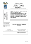
APPENDIX 3
FRONT PANEL CONTROLS SUMMARY
1. Vernier/Offset. Vernier function offsets sweep
ranges, CW or CF frequencies. ~o lamp lit
when non-zero offset or vernier present.
,,,,,\
•...../
2. Right Frequency Control. Adjusts
STOP frequency.
~F
or
3. Right Frequency Display. Displays STOP
or ~F frequency in GHz or MHz.
4. M KR·~. Allows user to display frequency
difference between any two markers and
intensifies the appropriate portion of the display.
10. Sweep Mode. Selects External. Manual, or
Timed sweep mode.
II. MARKER SWEEP. Causes Marker I frequency to temporarily become start of sweep,
Marker 2 frequency to become stop of sweep.
12. Sweep Trigger. Determines how sweep will
trigger.
13. M KR-+ CF. Causes center frequency of sweep
to be shifted to the frequency of the currently
active marker.
5. Frequency/Time Display. Display Marker
or manual sweep frequency in GHz or MHz.
Sweep Time in seconds and HP-IB address.
14. Line switch. Turns on/off 8350B mainframe
and plug-in.
6. Markers. Controls the five independent,
mainframe supplied frequency markers.
15. Instrument Preset. Selects a pre-determined
instrument state.
7. Save n/Recall n/Alt n. Can save and recall
up to nine different settings.
16. START/CF/CW/~F/STOP Sweep mode
keys. Selects mode of output and display.
8. Data Entry Keyboard. Can enter exact
values or step sizes for most sweep parameters
via the keyboard.
17. Left frequency Control. Adjusts START,
CW, CF, VERNIER or OFFSET.
9. Output Controls. Can control marker display mode, RF and display blanking and
internal square wave modulation (of the RF
output).
18. Left Frequency Display. Displays START,
CW, CF, VERNIER or OFFSET frequency in
GHz or MHz, depending on mode selected,
plus self test error codes.
Figure 18. Front Panel Controls
29