1
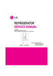
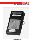
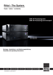
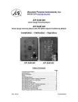
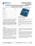
Weighing Indicator Service Manual V1.24X TRWS Weighing Indicator Service Manual CONTENTS PRECAUTIONS……………………………………………………………….3 SPECIFICATIONS….……………………………………………………….....4 INTRODUCTION…………………………..………………………………………..5 INSTALLATION……………………………………………………………………..6 Unpacking…………………………………………………………………………6 Installation……………………………………………………………………………6 Load cell connections..... ……………………………………………….........7 Connect Adaptor and Charging…………………………………………………..7 Quick Set Up……………………………………………………………7 Quick Calibration……………………………………………………………………9 5. NAME AND FUNCTIONS.... ……………………………………….......……..10 Overall view…………………………………………………………………………10 Display……………………………………………………………………………….10 Key board……………………………………………………………………………11 6. OPERATION.…………………………………………………………….…….12 Power ON/OFF……………………………………………………………………12 Zero…………………………………………………………………………………..12 Tare…………………………………………………………………………………..12 Sample Weighing…………………………………………………………………12 Check Weighing…………………………………………………………………….13 Enter to Menu……………………………………………………………………….13 Set Limits…………………………………………………………………………....13 Set check weighing mode. ……………………………………………………....13 Accumulation……………………………………………………………………….14 Accumulation automatically……………………………………………….15 Animal Weighing…………………………………………………………………...16 Peak Hold …………………………………………………………………………..16 7. PARAMETER…………………………………………………………………17 Key operation into the menu..…………………………………………………. 17 Parameter Block…………. ………………………………………………………..18 Program Parameters……………………………………………………….20 8. CALIBRATION………………………………………………………………..22 9. RS232 OUT PUT…………………………………………………………..25 10. MAINTENANCE………………………………………………………………28 10.1. General ……………………………………………………………..28 10.2. Error Codes…………………………………………………………29 10.3. Determine the Problem……………………………………………29 10.4. Check the Load Cell..………………………………………………30 10.5. Check Indicator Voltages…………………………………………..30 10.6. Problems and Solutions……………………………………………31 11. CIRCUIT DIAGRAM………………………………………………..…………..33 12. DRAWING………………………………………………………………………..37 1. 2. 3. 4. -2- TRWS Weighing Indicator Service Manual 1. PRECAUTIONS WARNING DISCONNECT ALL POWER TO THIS UNIT BEFORE INSTALLING, CLEANING, OR SERVICING. FAILURE TO DO SO COULD RESULT IN BODILY HARM OR DAMAGE THE UNIT. CAUTION Permit only qualified persons to service the instrument Before connecting or disconnecting any components, remove the power. Failure to observe these precautions bodily harm or damage to or destruction of the equipment. The weighing scale is a precision electronic instrument, handle it carefully. Do not install the scale in direct sunlight. Verify the local voltage and receptacle type are correct for the scale. Only use original adaptor, other could cause damage to the scale. Pluggable equipment must be installed near an easily accessible socket outlet. Avoid unstable power sources. Do not use near large users of electricity such as welding equipment or large motors. Avoid sudden temperature changes, vibration, wind and water. Avoid heavy RF noise. Keep the scale clean -3- TRWS Weighing Indicator Service Manual 2. SPECIFICATIONS Model Resolution TRWS 1/30,000 Indicator housing ABS Plastic Stabilisation Time 1 Seconds typical Operating Temperature Power supply (external) Calibration Display Interface Zero range Signal input range ADC Internal counts ADC update Load cell drive voltage 0°C ~ +40°C / 32°F - 104°F AC Adaptor (12V/500mA) / Ni-MH battery (1.2V/2000mAh x 6) Automatic External 6 digits 22mm LCD display, attached backlight RS-232 Output Optional 0mV~5mV 0~15mV Sigma delta 600,000 Max 60 times /second Max 5V/150mA -4- TRWS Weighing Indicator Service Manual 3. INTRODUCTION The TRWS series weighing indicator that amplifies signals from a load cell, converts it to digital data and displays it as a mass value. It is suitable for general weighing or more specialized applications such as check weighing, animal weighing and accumulation applications. It can connect the indicator to a printer or a PC. Large LCD with white LED back light display -5- TRWS Weighing Indicator Service Manual 4. INSTALLATION Unpacking When you receive the scale, inspect it to make sure that it is not damaged and that all are parts are included: Remove the Indicator from the carton. Remove the protective covering. Store the packaging and to use if you need to transport the scale later. Inspect the indicator for damage. Make sure all components are included. 1. Indicator 2. Adaptor 3. Manual 4. Indicator holder (Optional) 5. Load cell Output connecter (Optional) 6. RS-232 Output Connecter (Optional) Installation Place the Indicator on a table or connect with proper stand. Connect the plat form load cell cable in to the indicator load cell connecter. Load cell connecter is locating back side of the indicator. Connect the adaptor pin in to the indicator adaptor jack. Adaptor jack is locating, back side of the indicator. Adaptor connects into your AC power socket. Pluggable equipment must be installed near an easily accessible socket outlet with a protective ground/ earth contact. Turn on the On/Off key. If you want to turn off, press the key again. Display will be show the scale software version and will be start selfchecking. After self-checking, display will be come to normal weighing mode. Warm-up time of 15 minutes stabilizes the measured values after switching on. Calibrate with exact calibration weights, minimum 1/3 of the scale capacity want to use for calibration. For calibration see details in parameter. Then you can start your operation -6- TRWS Weighing Indicator Service Manual Load cell connections Connect the load cell cables to the terminal as shown table. It can connect four 350 ohm load cells. The load cell drive voltage is 5V DC ±5% between Excitation + and Excitation -. 5Pin Air Connector Pin 1 Signal + Pin 2 Signal Pin 3 Shield Pin 4 Exc Pin 5 Exc + Connect Adaptor and Charging To charge the battery insert the adaptor pin to jack. Adaptor simply plug into the mains power. The scale no needs to be turned on. The battery should be charged 12 hours for full capacity. The symbol status of the battery Battery voltage has dropped Low voltage Fully charged . Do not use any other type of power adaptor than the one supplied with the scale. Verify that the AC power socket outlet is properly protected. Note: Please charge the battery before using the scale for the first time. Quick Set Up Load Cell Connector (5 Pin Connector) Pin 1 Sig + Pin 2 Sig Pin 4 ExPin 5 Ex + -7- TRWS Weighing Indicator Service Manual RS-232 Out Put (9 Pin Connector) Pin 3 TXD Pin 2 RXD Pin 5 GND RS-232 Data Specification 8 data bits (Fixed) No Parity (Fixed) Baud Rate adjustable 600 to 9600 Ticket printer: set printer parameter to F4 Prt to P Prt, Select baud rate and printing format. Remote Displays, Set printer parameter F4 prt to SEirE , baud rate. Set Up: Note: To enter into the calibration mode operations, refer section 7; page 20 for to enter and access. Press key and key together, when in the weighing mode. Press continuous until display will be shows. prog Press , display will be show. Enter the password. Press Display will be show P1 ref , Press Press and , display will be show. P 2 cal key and select DECi, Press key and press confirm desired decimal point. Press , pin key to move decimal point, press key to advance to inC division, Press key and press confirm desired increment. key to change increment, press Press key to advance to CAP, Press key and enter full capacity by using digits) using press key to key to key (toggle between key (increase the numbers 0~9) after selecting full capacity key to save. -8- TRWS Weighing Indicator Service Manual Quick Calibration Note: To enter into the calibration mode operations, refer section 7; page 20 for to enter and access. Press key and key together, when in the weighing mode. Press continuous until display will be shows. prog Press , display will be show. Enter the password. Press Display will be show P1 ref , Press Press , pin and , display will be show. P 2 CAL key and press until to display show CAL Press key to select nonLin (not linear calibration, for simple zero and span calibration) Press , display will be show. calibrate in LB or KG by pressing UnLoad (at this time you can also choose key) Make sure nothing is on the scale , then press key. Display will be show last calibrated test weight value, if you want to change the test weight value, toggle between the digits by using digits) using value press key (toggle between key (increase the numbers 0~9) after selecting test weight key to save, display will be show LOAd (LB or KG you can still select the calibration unit by using Load test weight on the platform and press and automatically restart the indicator. key) key, display will show PASS -9- TRWS Weighing Indicator Service Manual 5. NAME AND FUNCTIONS Overall View BACK Display FUNCTION Check weighing FROUNT Indicator for Zero display Indicator for Tare display Indicator for Gross weight Indicator for Net weight Indicator for Display stability Indicator for Auto Accumulation Indicator for Accumulation Indicator for Animal Weighing Mode Indicator for Hold/ Lock Indicator for Charging status of battery. BACK DISPLAY HI OK LOW ZERO TARE GROSS NET STABLE AUTO M+ ANIMAL HOLD - 10 - TRWS Weighing Indicator Service Manual Key Board KEY FUNCTION Turn the power On/ Off Used to reset to Zero. In setting mode can use to confirm entry Used to recording tare values and change the value from gross value to net value. Insetting mode can use to increase the value and scroll forward in menu. When the scale has been tared and display is in gross or net mode. When using the settings mode, can use to move active digits right. For print the results, to the PC or printer using the optional RS232 interface. It also adds the value to the accumulation memory if the accumulation function is not automatic. When using the settings mode, can use to move active digits left. In settings mode, escape back to menu/ weighing mode. - 11 - TRWS Weighing Indicator Service Manual 6. OPERATIONS Initial Start – Up: Warm-up time of 15 minutes stabilizes the measured values after switching on. 1. Power ON/OFF: Switch on the balance by pressing key. The display is switched on and the test is started and if want to switched off, press again the key. 2. Zero Environmental conditions can lead to the balance exactly zero in spite of the platform not taking any strain. However, you can set the display of your balance to zero any time by pressing that the weighing starts at zero. key and therefore ensure 3. Tare The weight of any container can be tared by pressing button so that with subsequent weighing the net weight of the object being weighed is always displayed. Load weight on the platform. Press key. Zero is displayed, and tare is subtracted. Remove weight on the platform. Tared weight is displayed. It can set only one tare value. It can display with a minus value. Press G/N to change between gross weight and net weight. To clear the tare value, remove the load and press displayed, tare weight is cleared. key. Zero is 4. Sample weighing Place goods to be weighed on the platform. Wait few seconds for stability display. Read the result. Avoid overloading. When display appears “ol” reduce the load or unload. - 12 - TRWS Weighing Indicator Service Manual 5. Check Weighing It can set an upper or lower limit when weighing with the limits range. During the limit controls dividing the unit will indicate whether a value upper or lower limits with an alarm sound . For details see the parameter F3 oFF. Check mode 1: No beep sound in the limits. Function turned off. Check mode 2: When the weight is between the limits. OK will shown and beeper will be sounded. Check mode 3: When the weight is out of the limits, the beeper will be sounded and OK will shown. 6. Enter to Menu In the weighing mode, press Display will be appear and together. F0 H-L 7. Set limits Press to enter the function. Press key to select the limit. Display will appear Set Lo Press key to enter, press key to move active digits. Press to change the value. After enter the value press Press to escape. to sure. 8. Set check weighing mode. After entering the settings mode, Press Press F3 oFF until display will be appear key to enter, press until display show bEEP - 13 - TRWS Weighing Indicator Service Manual Press key to enter, press Check mode 1 bP 1 Check mode 2 bP 2 bP 3 Check mode 3 Select desired setting by pressing and press key to confirm, press to escape. Note: The load weight must greater than 20 scale divisions for the check weighing operations. To disable the check weighing function, enter zero into both limits. 9. Accumulation Accumulation Place the goods on the platform to be weigh Wait few seconds for display stable, then press saved and printed (if the printer is connected). Display will be appear appear two seconds only. ACC 1 . The value will be this display will Remove the load and wait few seconds for display return to zero. Place the second goods on the platform. Wait few seconds for display stable. Then press saved. . The value will be Followed by the total number of weight will be displayed ACC 2 It can continue the process until the maximum capacity or value. Note: When you change the weighing unit this saved values will be clear. - 14 - TRWS Weighing Indicator Service Manual Accumulated Total Manually, the scale can be set to accumulation by pressing optional printer is connected. See details in F4 Prt. , when an Memory Recall When display of Zero, you can see the number of weighing and total weight by pressing , display will be shown for two seconds. Delete the Memory When display of Zero, you can see the number of weighing and total weight by pressing , display will be shown for two seconds. Press during this display. The memory data are deleted and display will be shown ACC 0 10. Accumulation Automatically In this function the individual weighing values are automatically added into the memory. No need to press any keys. For this function, set to parameter F4 Prt and select P AutO. After select this function, display indicator AUTO will be shown. Place the goods on the platform to be weighed After the stable, will be follow beep sound twice. Unload the goods, the weighing value will be saved automatically and will be follow beep sound once. It can continue the process until the maximum capacity or value. - 15 - TRWS Weighing Indicator Service Manual 11. Animal Weighing TRWS can use for vibrate loads. For this function, set to parameter P4 CHk to ModE 2 After select this function, display will be show “ANIMAL “indication. Bring the load on to the platform. When the load few seconds get stable, the reading will be locked for few seconds and will be follow beep. It can add or remove loads also update the weighing locked values. 12. Peak Hold TRWS can operate peak hold function, maximum reading will be hold and will update automatically when add goods. For this function, select parameter P4 CHk to ModE 4 In the normal weighing mode press and key together to turn on Peak hold operations, display will be indicate HOLD. If want to turn off peak function, press and key together again - 16 - TRWS Weighing Indicator Service Manual 7. PARAMETERS KEYS OPERATIONS INTO THE MENU Enter the menu In weighing mode, press key and key together. Select the menu Press , it can change the menu block one by one. Using increase the digit. Enter the selected menu Press , it can confirm, which will be shown displayed. Change the digit Press , it can change the active digit. Return to weighing mode Press , exit from the menu. - 17 - TRWS Weighing Indicator Service Manual PARAMETER BLOCK Menu F0 H-L Weighing with set limits F1 toL Sub-Menu Description SET Lo Lower limit value SET Hi Upper limit value. to CLr Clear the accumulation memory with out printout Print the total accumulation memory and clear the total memory Print the total accumulation and keep all the memory. Weighing units to P-C to Prt F2 Unt kg g Oz LZ Bl El on El au F3 off beep El Bp Bp Bp F4 prt Display of back light on Display of back light on automatically off Display of back light off 1 Beep sound off during the check weighing 2 Beeper will be sounded with in the check weighing limits 3 Beeper will be sounded above the check weighing limits RS 232 mode P prt By pressing , weighing value will be added to the memory and print the print out P cont Seire Ask Send data continuous Also send data continuous Bi- direction , through PC Commands R= Send, T= Tare, Z= Zero P cnt 2 No documented P stab Send data of stable weighing values P auto Automatic accumulation. Individual weighing values are automatically added Set BAUD rate After setting the RS 232 mode, display will be shown current - 18 - TRWS Weighing Indicator Service Manual baud rate b XXX. Avail able baud rate: b600, b1200, b2400, b4800 and b9600 If necessary change the baud rate by pressing and enter by pressing Set print out format If enter settings p prt, p auto, p cont and connected optional printer Print format Pr X Only for p prt, p auto format Print format Lab X Cont 1 Only for p cont only Cont 2 N.A Cont 3 Set printer type prog Ty-tp Ticket printer Ty 711 Label printer Lp 50 Label printer Print and Accumulation On/Off Acc on Print and weighing data will be save into memory. Acc off Print and data will not save. pin Enter the programming and calibration menus by using password , and - 19 - TRWS Weighing Indicator Service Manual PROGRAM PARAMETERS Note: Prog parameters (P1 Ref / P2 Cal / P3 Pro) are protected by calibration switch. Before entering these functions press calibration switch to access. Menu Sub Menu A2n 0 P1 ref 0 – auto 0 – range Speed P 2 cal Deci Description oFF Auto zero point settings 0.5d 1d 2d 4d P1 0 Zero setting range. P1 2 When the display is turn on the scale is set to P1 5 zero P1 10 P1 20 P1 50 P 2 2 Manually zero setting range, by pressing P 2 4 P 2 10 P 2 20 P2 50 P 2 100 S 7.5 S 15 S 30 S 60 C 0 Decimal point settings - 20 - TRWS Weighing Indicator Service Manual Inc Cap cal P3 pro Tri Count P4 chk Reset Gra Mode 1 Mode 2 Mode 3 Mode 4 C 0.0 C 0.00 C 0.000 C0.0000 1 Increment settings 2 5 10 20 50 00000 Enter the scale capacity Linear Linear calibration nonlin Normal calibration This display will be show XXXXX. For trimming the load cells, showing primary weight. You can calculate new rate by this formula: N2=N1+N1×[(K2-K1)÷K2] N1: primary rate, N2: new rate, K1: calibrate weight, K2: display weight This display will show XXXXX for indicating the internal counts. Factory default settings Set the local gravity Normal weighing mode. (check weighing, accumulation) Animal weighing mode. (scale can lock reading, when little unstable) This is a subtraction scale (print out “-“ weight) As the mode 3, but M+ out format different - 21 - TRWS Weighing Indicator Service Manual 8. CALIBRATION Note: To enter into the calibration mode operations, refer section 7; page 20 for to enter and access. In weighing mode, press key and key together. Press continuous until display will be shown. Press , display will be shown. Enter the password. Press Display will be shown Press Press Press , and , display will be shown continuous until display will be shown. Enter the function by pressing , display will be shown to select for normal calibration Normal Calibration: prog pin , display will be shown. Enter the function by pressing Fo h-l P1 ref P 2 cal dec cal linear Nonlin Nonlin Enter the function by pressing , display will be shown Unload lb (at this time you can also choose calibrate in LB or KG by pressing key) - 22 - TRWS Weighing Indicator Service Manual Make sure there are no loads on the platform and wait few seconds for stable indicator on. Enter the function by pressing Currently adjustment , display will be shown If want to change by using the keys required setting , Enter the selected setting by pressing display will be shown. and , 05.000 lb to select the Load lb Load the calibration mass weight on the platform and wait few seconds for display stability. After the stable indicator on press shown. , display will be pass After the calibration the display will start a self test. Remove the load from platform during the test. Display will come to weighing mode automatically. If display will be shown any error or incorrect value, repeat the procedure again. Linear Calibration linear The linearity deviation caused by the performance of the weighing unit. The digital linearization function can reduce the linearity deviation using weighing points during the zero and capacity. Up to three weighing points can be specified. linear Enter the function by pressing , display will be shown Load 0 lb (at this time you can also choose calibrate in LB or KG by pressing key) - 23 - TRWS Weighing Indicator Service Manual Make sure there are no loads on the platform and wait few seconds for stable indicator on. Load 1 lb Enter the function by pressing , display will be shown Load the first calibration mass weight on the platform (mass weight should be1/3 of the max capacity) and wait few seconds for display stability. Then press , display will be shown Load 2 lb Load the second calibration mass weight on the platform (mass weight should be2/3 of the max capacity) and wait few seconds for display stability. Then press ,display will be shown Load 3 lb Load the third calibration mass weight on the platform (mass weight should be3/3 of the max capacity) and wait few seconds for display stability. Then press ,display will be shown pass After the calibration the display will start a self test. Remove the load from platform during the test. Display will come to weighing mode automatically. If display will be shown any error or incorrect value, repeat the procedure again. - 24 - TRWS Weighing Indicator Service Manual 9. RS-232 OUTPUT TRWS series scales can take out data through RS 232 output. Specifications: RS-232 output of weighing data Code : ASCII Data bits : 8 data bits Parity :No Parity Baud rate : 600bps to 9600bps selectable Connecter: Pin 2: Input Pin 3: Out put Pin 5: Signal Ground 9pin D type connector Pin 2 RXD Input Receiving data Pin 3 TXD Output Transmission data Pin 5 GND ― Signal ground 9pin D Connecter: Indicator Pin 2: Pin 3: Pin 5: Computer/ Printer Pin 3 Pin 2 Pin 5 Note: If data is not getting in PC, want to inter-change one of the Pin 2 and Pin3 connections Continuously output protocol Con1: , HEADER1 -/ HEADER2 k WEIGHT DATA g WEIGHT UNIT CR LF TERMINATOR HEADER1: ST=STABLE, US=UNSTABLE HEADER2: NT=NET, GS=GROSS - 25 - TRWS Weighing Indicator Service Manual Print Out Formats Note: Lab 0 & 2 for English and Lab 1 & 3 for Chinese Language Lab 0 Pr 0 2011/12/30 11:11 WEIGHT: 1.00kg NET: GROSS: TARE: 2011/12/30 4 11:11 WEIGHT: 1.00kg 2011/12/30 3 3 WEIGHT: 1.00kg TOTAL: 2 2 WEIGHT: 1.00kg 2011/12/30 1 1 NET: GROSS: TARE: TOTAL: TOTAL: 1.00kg NET: GROSS: TARE: 1.00kg 1.00kg 0.00kg NET: GROSS: TARE: TOTAL: 1.00kg 1.00kg 0.00kg 10.00kg 1.00kg 11:11 1.00kg 1.00kg 0.00kg 11:11 1.00kg 1.00kg 0.00kg 10.00kg 2011/12/30 11:11 S/NO: 10 S/NO: 10 WEIGHT: 1.00kg WEIGHT: 1.00kg 2011/12/30 5 S/NO: WEIGHT: TOTAL: 2011/12/30 6 S/NO: NET: GROSS: TARE: 11:11 10 1.00kg 10.00kg S/NO: WEIGHT: TOTAL: 10 1.00kg 10.00kg S/NO: NET: GROSS: TARE: 10 1.00kg 1.00kg 0.00kg 11:11 10 1.00kg 1.00kg 0.00kg - 26 - TRWS Weighing Indicator Service Manual 2011/12/30 7 S/NO: NET: GROSS: TARE: TOTAL: 11:11 10 1.00kg 1.00kg 0.00kg 10.00kg S/NO: NET: GROSS: TARE: TOTAL: 10 1.00kg 1.00kg 0.00kg 10.00kg - 27 - TRWS Weighing Indicator Service Manual 10. MAINTENENCE WARNING DISCONNECT ALL POWER TO THIS UNIT BEFORE INSTALLING, CLEANING, OR SERVICING. FAILURE TO DO SO COULD RESULT IN BODILY HARM OR DAMAGE THE UNIT. CAUTION Permit only qualified persons to service the instrument Before connecting or disconnecting any components, remove the power. Failure to observe these precautions bodily harm or damage to or destruction of the equipment. 10.1. General If the scale does not operate properly, find out the problem as possible. Determine whether the problem is constant or alternate. Be aware that problems can be caused by mechanical or electrical influences. Check the following. Water Corrosive materials Vibrations or temperature or wind Physical damage Check the indicator cables for damage, and check all connections and connecters for any loose contact or incorrect connection - 28 - TRWS Weighing Indicator Service Manual 10.2. Error Codes Indicator’s error message’s following lists ERROR CODES Error Message ----Err 1 Err 2 Err 4 Err 5 Err 6 Err 9 Description Solution Maximum load exceeded Unload or reduce weight Incorrect date Enter the date by using format “yy;mm:dd” Incorrect time Enter the time by using format “hh:mm:ss” Zero setting error Zero setting range exceeded due to switching on.(4%max) Make sure platform empty. Key board error Check the keys and connecter. A/D value out of range Make sure platform empty and check the pan is installed proper. Check the load cell connectors. Unstable Reading Check any air variation, vibration, RF noise and touching some where. Check the load cell and connecters. Err 17 Tare out of range --ol-- Over range Fai l h / fai l l Err p Ba lo / lo ba Calibration Error Printer error Battery low Remove the load and restart scale again. Remove the load. Re calibrate Re calibrate Check the printer and settings Re charge battery, check the voltages. 10.3. Determine the Problem Determine whether the problem is in the indicator or the platform Remove power from the system, and disconnect the indicator from the platform Connect the indicator to a load cell simulator - 29 - TRWS Weighing Indicator Service Manual Reapply power and test the indicator If problem goes away, its source is probably in the platform. Check the wiring, connecter, load cells and mechanical components of the platform. If problem persists, its source is probably in the indicator. Check the indicator voltages, connecters, cables and function programs. 10.4. Check the Load cell Remove power from the system, and disconnect the indicator from the platform Remove the load connecter from platform terminal. Check the moisture, or foreign material inside. Make sure all leads are connected and correctly. See the details of connections in the Installation section. Check load cell for proper input and output resistances Measuring Points + Exc to –Exc (Input) +Sig to –Sig (Output) Resistance 420Ω ±10Ω 350 Ω ± 0.3 Ω 10.5. Check Indicator Voltages If the problem is in the Indicator, use a multimeter to check the following voltages 10.5.1 AC Power Check the AC power socket out put voltage. Voltage must be a -20% and +10% of the normal AC voltage. 10.5.2 Adaptor Voltage Check the adaptor output cable connecter voltage Voltage must be minimum 9VDC and maximum 15VDC 10.5.3 PCB Input Voltage Check the PCB input power connecter voltage Voltage must be minimum 9VDC in to the pin AD+ 10.5.4 Check Battery Voltage and Charging Voltage 1. Check the Battery Voltage, Voltage must be minimum 6VDC. If below the 6VDC connect the adaptor for charging - 30 - TRWS Weighing Indicator Service Manual The battery voltage below the 5.5VDC, replace the battery and install new 1.2V/1200mAh battery. 2. Check the Battery Charging Voltage; Remove the battery connection terminals (Red and Black) from the battery. Connect the power and turn on the Indicator Voltage into the terminal minimum 6.5VDC 10.6. Problems and Solutions Problems Display is blank. No self test Blank display after self test OL or ------- ------- or NULL displayed Display is unstable Weight value incorrect Possible cause Mains power is turned off. Power supply faulty or not plugged. Internal battery is not charged. On/Off switch problem Pan not installed. Unstable weight, load cell damaged Common Solutions Check power is getting inside the scale and on/off switch is working. Verify the voltages, which is on the power labels. Maximum capacity exceeded. Load cell or mechanics damaged. Power supply faulty Check the platform is installed correctly. Try to turn on the scale again. Do the calibration again Weight is on the platform is below permissible limit. Pan not installed correctly. Power supply faulty. Load cell or mechanism faulty Check the platform is installed correctly. Try to turn on the scale again. Do the calibration again Goods touching somewhere. Air variation or any vibrations. Temperature changed . Load cell or connections faulty. Power supply faulty Calibration error. Platform of load cell touching somewhere. Check the scale is in acceptable location. Check the connecters and load cell. Check the power supply and battery Check the pans are installed correctly. Try to turning on again. Use accurate weight for to do the calibration Check the pan and load cell is - 31 - TRWS Weighing Indicator Service Manual Wrong weighing unit Can not use full capacity Over load protection stoppers or transport locks are not removed. Parameters are set incorrectly. AD problem. Load cell or mechanism damaged Platform Corner Weight different Over load protection stoppers or transport locks are not removed. Load cell or mechanism damaged Mains voltage problem Charging circuit problem Battery Problem Battery not charging installed proper and touching. Check the parameter settings. Check the load cell and connecters Check the stoppers and locks under the platform. Check the weighing unit and parameter settings. Check the load cell. Check the stoppers and locks under the platform. Use accurate weight for to do the calibration Check the load cell. Check the mains and adaptor. Check the battery. Check the charging circuit - 32 - TRWS Weighing Indicator Service Manual 11. CIRCUIT DIAGRAM Indicator Circuit Diagram - 33 - TRWS Weighing Indicator Service Manual - 34 - TRWS Weighing Indicator Service Manual - 35 - TRWS Weighing Indicator Service Manual - 36 - TRWS Weighing Indicator Service Manual 12. DRAWING No 1 Parts Name Display Overlay 2 3 4 Display Acrylic Board Up Cover Key Head 5 6 7 8 Main Board M3 Insulation Gasket Cross Round Screws Cross Round Screws 9 10 Ni-MH Battery Metal Water proof threading Head Component 11 Round Adaptor Base Component 12 13 Adaptor Rubber Stuff Flat Gasket 14 15 16 Battery layering Seal Ring Plastic 17 18 19 20 Bottom Case Gross Round Screws Seal Gasket Cover Gasket 21 22 23 M4 Spring washer Hand Tighten Screws Support Frame Bush 24 Support Frame - 37 - The product range can be summarized as follows: Counting scales for general industrial and warehouse applications. Digital weighing/check-weighing scales. High performance platform scales with extensive software facilities including parts counting, percent weighing etc. Digital electronic scales for medical use. Retail price computing scales. Floor scales. Truck scale. Crane scales. Weighing indicator for platform scales, floor scales and truck scales. Hand push and pull gauge. Customize auto weighing systems. Totalcomp Inc. 99 Reagent Lane Fair Lawn, NJ 07410 Tel.: 800-631-0347 Fax: 888-797-2288 All information contained within this publication was to the best of our knowledge timely, complete and accurate when issued. However, we are not responsible for misimpressions which may result form the reading of this material.