1
MAC 2000 Wash Service Manual
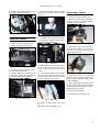
Main PCB, replace
See the electrostatic discharge precautions
on page 2.
1
the control panel) and connect it to
PL57. Connect the left base fan to
PL55. Connect the 4-pin lead from the
control panel to PL33.
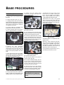
Remove the front top base cover.
2 Remove the top screws from the
front side cover and swing the cover
down to expose the main PCB.
3
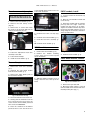
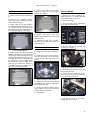
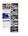
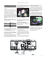
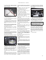
Fig. 100 DMX, control panel, and fan
connection
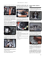
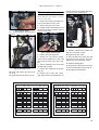
5 Check the jumper caps on the
replacement board. The normal positions are as follows:
10 Connect the rectangular 8-pin plug
from the power supply to the socket at
the top of the PCB.
write
enable
boot
normal
data
receive/send
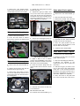
6 Connect the blue, brown, and black
high voltage wires to the PCB as shown
on the connection label.
7
Install the PCB on the front cover.
Install and fasten the replacement.
7 Connect the brown wire to PL101
and the blue wire to PL102. These
wires are slightly heavier than the
brown and blue wires going to the relay.
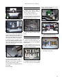
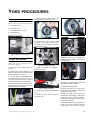
4 Remove the nuts along the top edge
with a 5.5 mm socket wrench. Lift the
top edge of the PCB over the screws
and then lift the bottom edge out of the
track.
Default position
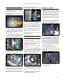
5 Remove 2 nuts from the top and 3
nuts from the bottom of the circuit board
with a 5.5 mm socket wrench and
extension. You may also need a 5.5 mm
open-end wrench to hold the stand-offs.
Remove the power module.
6
Disconnect all wires from the PCB.
Jumper
wires so you can get to the nuts at the
bottom of the power supply.
brown
11 Connect the remaining wires as
shown on the connection label.
blue
12 Upload software if required and
reinstall the covers.
Power supply, replace
1 Verify that the fixture is disconnected from AC power.
2
Remove the front top base cover.
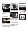
8 Connect the 2-wire electronic ballast
dimmer cable to PL215. (The ballast
end is shown in Fig. 104.)
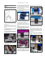
3 Disconnect the blue and brown
wires at the top of the power supply
PCB and unplug the 8-pin connector on
the right.
9 Connect the large unlabeled 4-pin
plug at the bottom of the PCB. Follow
the lead from the right base fan (next to
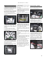
4 Remove the front side cover and
disconnect the blue, black, and brown
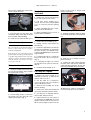
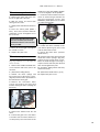
Fig. 102 AC input
8
Plug in the 8-pin connector.
9 Reconnect the brown, black, and
blue lamp power wires to the main PCB
as shown on the connection label.
10 Reinstall the covers.
Fig. 101 PCB connections
18