1
HEAD PROCEDURES
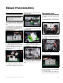
Zoom module, remove
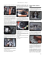
the thermo-sensor, which is in front of
the junction print.
1 Lock the head in the horizontal, top
up position.
The color wheel module remains
attached to the zoom module in
this procedure.
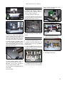
2 Place the ends of the wire bundles
outside of the head, forward of the
yoke.
1 Remove the top and bottom head
covers and the front lens. Fully back out
the thumbscrew for the lens retaining
wire.
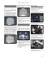
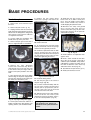
2 Unplug cables from the outside row
of the left-side zoom module junction
print. Unplug the unlabeled 2-pin connector from socket 38.
Zoom module, install
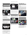
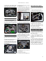
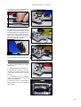
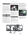
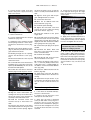
Fig. 3 CMYC thermo-sensor PCB
5 Unplug connector 16 from the dimmer junction print.
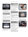
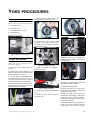
Fig. 6 Place wires forward of yoke
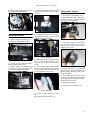
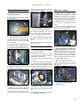
3 Lower the module into the chassis,
working it past each “sticking point” in
turn. Fasten.
Fig. 1 Unplug left junction print
Fig. 4 Dimmer junction PCB
3 Unplug the wires from the outside
row of the right-side zoom module junction print. Unplug connectors 42, 23,
and the unlabeled 2-pin fan plug from
the inside row.
6 Remove the 4 zoom module fastening screws.
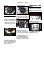
Fig. 7 “Sticking points”
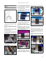
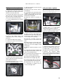
4 Reconnect the wires to the left and
right junction prints.
Fig. 5 Zoom module screws
Fig. 2 Unplug right junction print
7 Pull the zoom module (and attached
color wheel module) up, out of the
head.
4 Unplug the wires from the back row
of the CMYC module junction print and
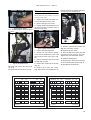
Fig. 8 Right junction connections
5 Plug connector 16 into the dimmer
junction print. (Fig. 4)
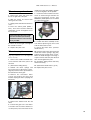
6 Insert the CMYC wire bundle into
the slot in the zoom module. Connect
© 2002 Martin Professional A/S, Denmark. Updated December 23, 2002
3