1
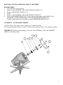
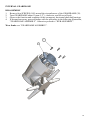
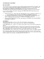
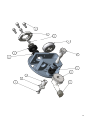
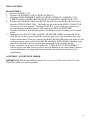
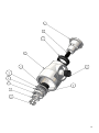
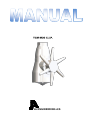
JA ENGINEERING A/S
TABLE OF CONTENTS
2.
TABLE OF CONTENTS
3.
SERVICE MANUAL
SPARES
TOOLS
SERVICE
5.
PART LIST
7.
INLET ASSEMBLY WITH 2103S
8.
INLET ASSEMBLY WITH 2103R
9.
BOTTOM COVER AND PRIMARY SHAFT ASSEMBLY
10. INTERNAL GEARFRAME
11. GEARFRAME ASSEMBLY
13. HUB ASSEMBLY
15. STEM AND CLUTCH ASSEMBLY
2
SERVICE MANUAL
T.C.M. TANK CLEANING MACHINES
When delivered, the Tank Cleaning Machine is ready for immediate use.
Care should be taken during use. Before connecting, flush all liquid lines and valves to
purge the system of foreign matter which could cause blockage of liquid flow. It may be
advisable to provide a filter (MESH 0,1-0,2mm) prior to the machine or suction side of the
supply pump if the system is prone to such occurrences.
IMPORTANT: When connecting top cone thread to supply pipe, use OMNIFIT 100M
(one part water proof glue) or a similar product to secure the TC Machine from
unintentional loosening from supplypipe.
All piping or hose must have a minimum of 1 1/2" (38mm) I.D. to insure adequate volume
and pressure are available at the machine.Operating pressure can vary between 3.5 and 10
bar (50 to 150 p.s.i.) depending on the nozzle configuration, to attain desired thru-put,
radius of cleaning and cycle time. Please refer to the Capacities Chart in this manual when
ordering or putting the machine into operation. Inadequate as well as excessive pressure will
adversely effect performance.
Operating temperatures can vary between 2 to 95 deg.C (35 to 200 deg.F) (Above freezing
and below boiling temperature.) The machine is Liquid-Hydraulically Motivated and no
attempt should be made to operate it with steam, air or gas. After each use, the machine
should be flushed and allowed to drain completely. Entrapped water may cause severe
damage in freezing atmosphere.
Always open liquid supply valve slowly, to avoid hydraulic shock from entrapped air, etc.
Repeated shock and surges can cause damage to piping, hose and other equipment as well
as to the Tank Cleaning Machine.
The following information on your machine(s) should be documented and referred to when
inquiring for information or ordering spare parts, etc.
1. Model number:
2. Serial number:
3. Parts: a. Quantity required:
b. Item No:
c. Parts No:
d. Description:
3
SPARES
Maintenance and repair of T.C.M. Tank Cleaning Equipment as described and illustrated
herein, is not difficult.
If you choose to maintain the equipment rather than return to us for overhaul, we recommend a minimum of spare parts be stocked at your facility. This will minimize the downtime of its very important cleaning function. Most importantly, maintenance personnel can
compare the wear of various parts in the machine with the new parts. In this way it can be
determined, on-site, if at least a "half service life" is still available for a particular part. This
will reduce maintenance cost by unnecessary and premature replacement of useable parts.
For in-plant maintenance as described, we recommend:
Minimum
1
1
1
1
1
2
1
2
4
4
Item No.
9
11
16P
16S
26BR
26R
28S
29C
18S
33H
Part No.
2109C
2111P
2116PTZ
2116S8
2126BR
2126R
2128S
2129C
2118S
2133H
Description
Primary Shaft Bushing
Primary Shaft
Wormgear, Primary
Wormgear, Secondary
Thrust Balls & Retainer
Thrust Race
Secondary Shaft Horizontal
Shaftbearing
Socket Screw 3/16" x 1/2" Stainless
Hexhead Screw 3/16" x 1/2" Stainless
Please Never substitute steel screws for stainless steel as supplied with the machine.
Corrosive and aggressive products may cause rapid deterioration and make repair difficult
and costly.
Note:Periodically, a factory service check is recommended. Not later than 500 hours
TOOLS
Hexagonal screw driver SW4 or 5/32"
Open Ended or Socket Wrench SW8 or 5/16"
Hexagonal Key-2mm for HUB set screw
Pin Spanner-2in. Capacity x 3/16" pins
Screwdriver
SERVICE:
Whenever the machine ceases functioning and prior to a general overhaul or returning to
the factory for service, please make sure there are no obstructions or blockage from debris
preventing flow of cleaning fluid.
Disconnect the machine and unscrew the NOZZLES to remove any debris. Also remove the
INLET NIPPLE and GUIDE so that the IMPELLER can be rotated and any obstructions
removed. Back flush with air or water to completely evacuate any foreign materials. Reassemble the machine and test by putting into service. If unsuccessful, perform an overhaul as
per instructions or return to JA ENGINEERING A/S for routine service.
4
MODEL 20 PARTS LIST
Item No
2FB
2FS
2MS
3
3R
4
5
9
11
12
13
14
15C
16P
16S
17
18S
19
21
21G
22
23
24C
24/2
24/4
24/6
24S
26BR
26R
27
27U
27L
27H
28S
29C
30
31
33C
33V
33
33H
Part No.
2102FB
2102FS
2102MS
2103S
2103R
2104V
2105S
2109C
2111P
2112
2113
2114
2115C
2116PTZ
2116S8
2117
2118S
2119
2121ND
2121G
2122
2123 Nozzle,
2124C
2124MD2
2124MD4
2124MD6
2124S
2126BR
2126R
2127
2127/1Q
2127/2Q
21273Q
2128S
2129C
2130
2131
2133C
2133V
2133L
2133H
Description
*Material
Inlet Nipple: Female BSPS Thread
SS
Socket Screw 3/16" x 3/4"
SS
Socket Screw 3/16" x 1/2"
SS
Guide Standard
SS
Guide Ring (optional high truput)
SS
Stem
SS
Impeller Standard
SS
Primary Shaft Bushing
C
Primary Shaft
SS
Gearwheel
SS
Clutch
SS
Pinion Gear
SS
Collar Bush
C
Wormgear Primary
SS/TC
Wormgear Secondary
SS
Pinion Sleeve
SS
Socket Screw 3/16" x 1/2"
SS
Washer
SS
Hub Cover
SS
Hub Cover Gasket
T
Bevelgear
SS
various Orifice 6-7-8-10-14mm
SS
Hub Connector
SS
Hub, 2 Nozzle
SS
Hub, 4 Nozzle
SS
Hub, 6 Nozzle
SS
Set Screw for MD Hub
SS
Thrust Balls & Retainer
SS/T
Thrust Race, (2 per set)
SS
Body with Bushings (Factory Service) SS
Body Bushing Upper (Factory Service) SS
Body Bushing Lower (Factory Service) SS
Body Bushing Hub (Factory Service) SS
Secondary Shaft Horizontal
SS
Shaftbearing
C
Gearframe
SS
Bearing Support Cover
SS
Bottom Cover C.I.P.
SS
Valve for 2133C
SS
Bottom Cover, Portable Model
SS
Hexhead Screw 3/16" x 1/2"
SS
*Material: SS = Stainless Steel, TC = Teflon Compound, T = Teflon, C = Carbon
5
ASSEMBLY PICTURES AND DESCRIPTIONS
6
INLET ASSEMBLY WITH 2103S
DISASSEMBLY:
1. Remove six screws (2FS) from INLET NIPPLE (2)
2. Lift off INLET NIPPLE
3. Remove GUIDE (3)
4. After inserting a screwdriver through the vanes of the IMPELLER (5) to prevent
rotation, Using HEXKEY, REMOVE SCREW (18S) and WASHER (19) from
PRIMARY SHAFT (11).
5. Remove IMPELLER (5)
ASSEMBLY - IN REVERSE ORDER.
NOTE: Please never use exessive force or heavy blows to remove or assemble parts. .
Many parts are designed with close tolerances and damaged parts as well as
worn parts may cause the unit to be inoperable.
IMPORTANT: When reassembling, secure the six screws (2FS) with OMNIFIT 100M
(one part waterproof glue) or a similar product.
7
INLET ASSEMBLY WITH 2103R
DISASSEMBLY:
1. Remove six screws (2FS) from INLET NIPPLE (2)
2. Lift off INLET NIPPLE
3. Remove GUIDE RING (3R)
4. After inserting a screwdriver through the vanes of the IMPELLER (5) to prevent
rotation, Using HEXKEY, REMOVE SCREW (18S) and WASHER (19) from
PRIMARY SHAFT (11).
5. Remove IMPELLER (5)
ASSEMBLY - IN REVERSE ORDER.
NOTE: Please never use exessive force or heavy blows to remove or assemble parts. .
Many parts are designed with close tolerances and damaged parts as well as
worn parts may cause the unit to be inoperable.
IMPORTANT: When reassembling, secure the six screws (2FS) with OMNIFIT 100M
(one part waterproof glue) or a similar product.
8
BOTTOM COVER & PRIMARY SHAFT ASSEMBLY
DISASSEMBLY
1. Turn machine up-side-down.
2. Remove four SCREWS (33H) in BOTTOM COVER (33C)
3. Remove BOTTOM COVER (33C)
4. Drain.
5. Remove four SCREWS (18S) in BEARINGCOVER (31).
6. Press out PRIMARY SHAFT (11) from opposite end along with SCREW (18S)
WASHER (19) SHAFTBEARING (29C) and BEARINGCOVER (31).
Further, disassemble this assembly to check SHAFTBEARING (29C)*
ASSEMBLY - IN REVERSE ORDER.
* If bore I.D. is 10.4 mm or more, and or oval, replace bearing.
If horizontal bearing surface is worn 0.75 mm or more deep, and or oval, replace bearing.
IMPORTANT: When reassembling, secure the four SCREWS (33H) with OMNIFIT
100M or a similar product
9
INTERNAL GEARFRAME
DISASSEMBLY
1. Remove four SCREWS (18S) around the circumference of the GEARFRAME (30)
2. Turn GEARFRAME about 10 mm (1/2"), clockwise, and lift out of body.
3. Observe the function and condition of the wormgears, horizontal shaft and bearings.
4. If deemed necessary, proceed further with the procedure in the following illustration,
"GEARFRAME ASSEMBLY". Otherwise proceed to "HUB ASSEMBLY".
Wear limits: see "GEARFRAME ASSEMBLY".
10
GEARFRAME ASSEMBLY
DISASSEMBLY
It is necessary to prevent rotation of parts while removing screws from this assembly. This
can be done by placing and firmly holding the PRIMARY SHAFT (11) horizontally onto
and engaging the PRIMARY WORMGEAR (16P), thus preventing rotation of the
WORMGEAR and SECONDARY HORIZONTAL SHAFT (28S). Proceed to loosen all
screws in the assembly. Thereafter, disengage the PRIMARY SHAFT and all parts can
easily be disassembled.
1.
2.
3.
PINION GEAR (14), SECONDARY WORMGEAR (16S) and PINION SLEEVE (17)
can be withdrawn after removing the SCREW & WASHER (18S & 19).
SECONDARY HORIZONTAL SHAFT (28S) and PRIMARY WORMGEAR (16S)
can be withdrawn after removing the SCREW & WASHER (18S & 19).
Release SHAFTBEARING (29C) by removing four SCREWS (18S) from BEARING
SUPPORT COVER (31).
ASSEMBLY
Inspect and reassemble in reverse order after replacing parts as necessary.
If WORMGEAR (16P or 16S) is extreemly worn, replace the WORMGEAR.
COLLARBUSH (15C) : If I.D. is 13.4 mm or more and or worn oval it must be replaced as
follows :
Press out the COLLAR BUSH with a wooden dowel (support below the gearframe when
squeezing out the collar bush). Remove residue from glue and clean the bore in gearframe.
Put on OMNIFIT 230L or similar on the new collar bush and squeeze it into place.
Check BEARING (29C). If bore I.D. is 10.4 mm or more and or worn oval, replace bearing.
Also check the axial surface of the bearing, if worn 0.5 mm deep or more, replace bearing.
Inspect HORIZONTAL SHAFT (28S) and PINION GEAR (14), if worn in gear and bearing
surface, replace the worn parts, including PINION SLEEVE (17).
11
12
HUB ASSEMBLY
DISASSEMBLY
1. Remove NOZZLE (23)
2. Remove six SCREWS (33H) in HUB COVER (21).
3. Withdraw HUB ASSEMBLY: HUB (24), HUB COVER (21), GASKET (21G),
THRUST BALLS (26BR), BEVELGEAR (22) and HUB CONNECTOR (24C).
4. Remove SET SCREW (24S) from HUB. This will allow the HUB to be unscrewed
from the HUB CONNECTOR . Two holes are provided in the HUB CONNECTOR
for the use of a "pin spanner". Holding the HUB in a vise, (with jaw protectors to
prevent damage to polished parts), and rotating the HUB CONNECTOR
(counter-clockwise) with the pin spanner, the balance of this assembly can be taken
adrift.
5. Inspect the two RACES (26R) and BALL RETAINER (26BR) in particular. If the
RACES are severely grooved and the assembly does not rotate smoothly, they may
require replacement. First try replacing the BALL RETAINER and check again. If still
no improvement, then replace both RACES and BALL RETAINER. Ordinarily these
parts may deteriorate due to exessive grit and solids in the cleaning media.
There is another set of races in the body. See "STEM & CLUTCH ASSEMBLY".
Unless special care and tools are used to prevent damage to the races during removal
and reinstallation, it is suggested that the machine be returned to the factory for
replacement.
ASSEMBLY - IN REVERSE ORDER.
IMPORTANT: When reassembling, secure the six screws (21H) and nozzle (23) with
OMNIFIT 100M or a similar product.
.
13
14
STEM & CLUTCH ASSEMBLY
DISASSEMBLY
To prevent rotation of the stem during disassembly and reassembly, insert a screwdriver
through the water passage holes in STEM (4) so that it engages the body.
1.
2.
3.
4.
5.
6,
Remove six SCREWS (18S) from CLUTCH (13).
Pull out GEARWHEEL (12) together with its THRUST RACE (26R), THRUST
BALLS & RETAINER (26BR) and CLUTCH (13).
Inspect the two RACES (26R) and BALL RETAINER (26BR) in particular. If the
RACES are severely grooved and the assembly does not rotate smoothly, they may
require replacement. First try replacing the BALL RETAINER and check again. If still
no improvement, then replace both RACES and BALL RETAINER. Ordinarily these
parts may deteriorate due to exessive grit and solids in the cleaning media.
There is another set of races in the body. See "HUB ASSEMBLY".
Unless special care and tools are used to prevent damage to the races during removal
and reinstallation, it is suggested that the machine be returned to the factory for
replacement.
Press out STEM (4).
With a wood dowel or other relatively soft object, drive out the PRIMARY SHAFT
BUSHING (9) in direction illustrated.
Check condition of bore in PRIMARY SHAFT BUSHING (9). If bore I.D. is 13.4mm
or more and or worn oval, replace PRIMARY SHAFT BUSHING.
Glue PRIMARY SHAFT BUSHING into stem with OMNIFIT 230L or a similar
product.
IMPORTANT: When reassembling, secure the six SCREWS (18S) with OMNIFIT 100M
or a similar product.
NOTE: BODY (27) BUSHING (27U-27L and 27H) are factory service.
15
16