1
Compression Sense Ignition
continued from page 1
Ignition Control Module
Ignition Cassette Disassembled to Reveal Components
Compression Sense
At the moment an ignition coil fires, a
growing voltage potential is created across
the gap of both plugs. After about 10
microseconds, the voltage reaches each
plug’s breakdown voltage level. Breakdown is
the point at which the air gap ionizes and
conducts current, causing the spark to occur.
The breakdown voltage level is determined in
part by the pressure within the cylinder.
More voltage is required at a higher cylinder
pressure.
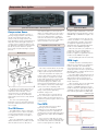
CSI Components
Ignition
Control Module
Connector
these capacitor plates is connected to the
ignition secondary outputs. The other side is
connected to a resistor network. As current
flows on the capacitor plates, a voltage is
created on this resistor. The voltage pattern
measured across this resistor is what makes
up the information in the CSI signal.
Firing Order 1/4 - 3/2 - 4/1 - 2/3
Spark Plug Boots
A cylinder on its exhaust stroke has less
in-cylinder pressure than a cylinder on its
compression stroke. Because of these
uneven pressures, the spark plug of the
cylinder on its exhaust stroke will break
down first (by a few microseconds), and will
spark first.
The order of the spark plug gap
breakdown events for the paired cylinders is
yet another characteristic that is reflected in
the CSI signal.
The CSI Sensor
The L850 utilizes a unique Compression
Sense Ignition sensor to detect the polarity
events and the breakdown events in the
secondary ignition circuits of each pair of
cylinders.
This is accomplished by creating virtual
capacitors between the secondary coils and
the EI module’s electronics. One side of
As the chart above shows, when the 1/4
coil fires, as cylinder 1 is on compression, the
event will generate a negative, then positive
CSI signal. This negative then positive CSI
signal will cause the CSTO chip inside the EI
module to send a CAMOUT high signal.
Cylinder on
Exhaust
(waste spark)
fires first
Cylinder on
Compression
fires second
4 - voltage
1 + voltage
2 - voltage
3 + voltage
1 + voltage
4 - voltage
PCM Logic
3 + voltage
2 - voltage
A variable reluctance crankshaft position
(CKP) sensor is mounted in the engine block
near the crankshaft. The crankshaft has
seven machined notches, six of which are
evenly spaced. The 7th notch is positioned at
50 degrees ATDC of cylinder 1/4 and is used
by the PCM as a sync pulse.
Cover
Coil
Housing
recognizes unique characteristics of the CSI
input signal, then decides whether to send a
CAMOUT high or CAMOUT low signal to the
PCM.
The resistor network allows only the high
frequency edge of the plug gap breakdown
voltage to pass through for measurement.
We know that cylinders fire in pairs, and
from the earlier study on polarity, we know
that the voltage of one plug moves toward
positive while its pair moves toward negative.
And from the breakdown discussion, we
know that the plug in the cylinder on the
exhaust stroke fires slightly before the one on
the compression stroke. These relationships
can be seen in the accompanying chart.
The CSI signal will reflect the polarity and
timing of each cylinder’s spark plug
breakdown voltage event.
Now that we have seen all the various
pieces of information contained in the CSI
signal, as well as the method in which it is
acquired, let’s pull it all together and see how
it is processed.
When the 1/4 coil fires, as cylinder 4 is on
compression, the event will generate a
positive, then negative CSI signal. This
positive to negative CSI signal will cause the
CSTO to send a CAMOUT low signal.
The 2/3 cylinder pair works the same way.
The engine always starts firing the 2/3 coil
first during cranking. Charging of the 2/3 coil
always begins near the 2nd crank notch.
Charging of the 1/4 coil always begins near
the 5th crank notch.
Once the ignition process has started with
the 2/3 coil, the PCM will look for the
sequence of CAMOUT signals from the EI
module to determine engine phasing. After 2
crankshaft revolutions, all four cylinders will
have fired and generated the 4 CAM ID bits.
continued on page 4
Firing Voltage Polarities
EST Signal
Coil fires
The CSTO
The EI module houses the CSI input
signal logic electronics called the
Compression Sense Time Out (CSTO) chip.
The CSTO electronics are responsible for
interpreting the CSI input signal and creating
a 5V square wave output called a CAMOUT
signal.
Here’s how the CSTO chip logic works.
The first EST rise of either cylinder pair alerts
the CSTO circuitry, and the CSTO chip looks
for the CSI input signal. The CSTO chip
3
Cylinder
on waste
Firing
voltage
rises in
Positive
direction
Breaks over
in a Negative direction
Cylinder on compression
Firing
voltage
rises in
Negative
direction
Breaks over
in a Positive direction
Return to page 1