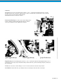
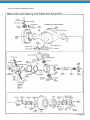
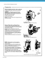
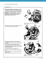
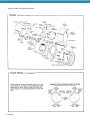
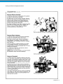
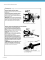
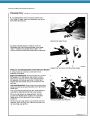
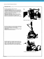
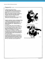
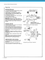
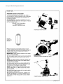
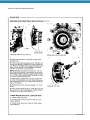
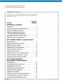
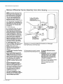
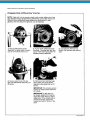
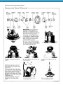
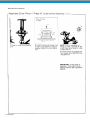
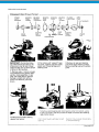
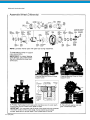
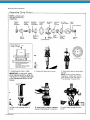
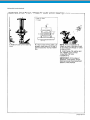
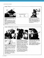
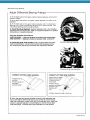
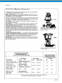
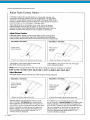
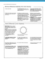
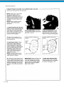
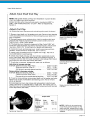
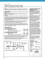
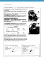
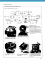
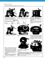
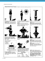
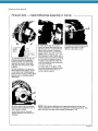
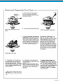
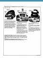
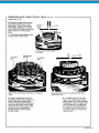
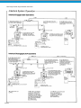
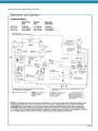
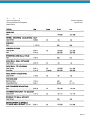
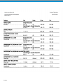
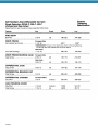
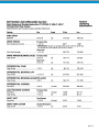
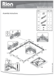
1
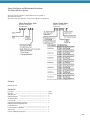
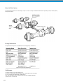
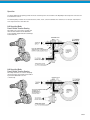
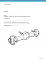
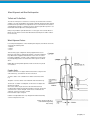
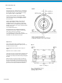
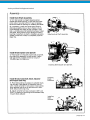
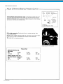
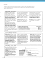
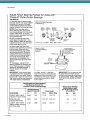
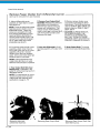
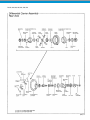
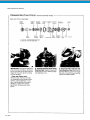
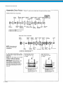
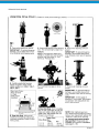
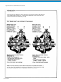
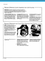
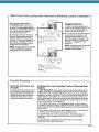
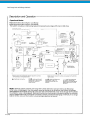
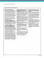
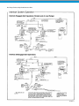
Spicer® Drive Axle Service Manual Spicer® All Wheel 6 x 6 Drive System AXSM-0600 February 1994 Spicer All-Wheel 6x6 Drive System Spicer Axles & Brakes Spicer Steer-Drive Axles ESD-18 Spicer 6x6 Tandem Axles D346-P, 386-P, 406-P, 466-P, 486-P, 586-P,656-P, Gearing: Single Reduction, Dual Range, Double Reduction Spicer Axle Service and Maintenance Instructions The Spicer 6x6 Drive System Spicer presents this publication to aid in maintenance and overhaul of Spicer 6x6 Drive Systems. Axle models and other equipment covered in this publication are listed below. Spicer Tandem Axles Spicer Steer-Drive Axles Model No. Identification Steer-Drive Axle Model No. Identification Tandem Axle Contents 6x6 Drive System Section No. Description -------------------------------------------------------------------Operation --------------------------------------------------------------------Steer-Drive Axle --------------------------------------------------------------Differential Carriers ----------------------------------------------------------Tandem Drive Axle -----------------------------------------------------------Power Divider -----------------------------------------------------------------Differential Carriers(Single Reduction) --------------------------------------Differential Carriers (Dual Range and Double Reduction) ------------------------------------------------------------Controlled Traction Differential ----------------------------------------------Shift Systems -----------------------------------------------------------------Fastener Tightening Specifications ------------------------------------------- page ii page iii 1 2 3 4 5 6 7 8 9 6x6-i Spicer 6x6 Drive System The Spicer 6x6 Drive System is a new-design concept. It consists of an Spicer standard tandem axle incorporating a unique transfer gearing in the power divider Spicer Tandem Axle Gearing Combinations The Spicer 6x6 Drive Systems are available in the following gearing combinations: Shift Systems The vehicle operator uses cab-mounted air con trol valves to change drive system operating modes, axle range selections and operation of controlled traction differentials. Detailed descrip tions of air shift systems which control these functions are contained in the Shift System Section of this manual. 6x6-ii Operation The power divider transfer gearing provides the means to deliver power to the steer-drive axle. Operating modes and power flow are shown in the illustrations below. The transfer gearing includes two mechanical clutches, which, in turn, control the drivelines from transmission to the input shaft and from front output shaft to the steer-drive axle. 6x6 Operating Mode Power Divider Transfer Gearing Driver flips an air control valve to engage steer drive axle and tandem inter-axle differential lockout. Gearing: Single Reduction, Dual Range, Double Reduction 6x6 Operating Mode Power Divider Transfer Gearing Driver flips valve back, two clutches disengage removing torque from steer-drive axle and allow ing inter-axle differential to function conventionally. 6x6-iii Service and Maintenance Instructions ESD-18 Steer-Drive Axle Section 1, Page No. Contents ESD-18 STEER-DRIVE AXLE Introduction ------------------------------------------------------------------------------------------------------ 2 Steering and Wheel End Equipment Steering and Wheel’End Inspection --------------------------------------------------------------------------- 3 Lubrication ------------------------------------------------------------------------------------------------------ 6 Overhaul ------------------------------------------------------------------------------------------------------ 7 Differential Carrier Section 2, Page No. Contents ----------------------------------------------------------------------------------------------------- 1 Lubrication ----------------------------------------------------------------------------------------------------- 2 Cleaning, Inspection and Replacement Adjustments ----------------------------------------------------------------------- 4 ----------------------------------------------------------------------------------------------------- 6 Differential Carrier Replacement ------------------------------------------------------------------------------- 10 Differential Carrier Overhaul Single Reduction ----------------------------------------------------------------------------------------------- 13 --------------------------------------------------------------------------- 22 Dual Range and Double Reduction 1-1 (4x4) (6x6) ESD-18 Steer-Drive Axle Introduction This manual includes instructions for the Spicer ESD-18 Steer-Drive Axle (capacity rating 18,000 lbs.). This axle may include one of three types of gearing: single reduction, dual range or double reduction. The single reduction gearing may be equipped with an Spicer Controlled Traction Differential. For service information on this special differential, refer to separate section in this manual. The axle housing is one piece. A special ball and socket assembly and wheel end equipment are provided at each end of the housing. The axle shaft assembly on each side of the axle is equipped with cardan-type universal joint. These joints are housed in a trunnion-type ball and socket assembly to provide steering capabilities. The axle is equipped with Spicer Single-Anchor Pin Air Brakes (16-1/2” x 5”). (4x4) (6x6) 1-2 ESD-18 Steer-Drive Axle Wheel Alignment and Wheel End Inspection Wheel Alignment Specifications Wheels Camber ............................. 1/2° Caster ................................. J0 Toe-in . . . . . . . . . . . . . . . . . . . . . . . . . . . 0 + 1/8” 1. Wheel stud nuts should be inspected and tightened twice in the first 500 miles, and again after 1,000 miles to avoid accidental loosening of the wheels. Loose wheel stud nuts may cause shimmy and vibration. Elongated stud holes in the wheels may also result from loose stud nuts. General Inspection Proper wheel alignment promotes longer tire wear, ease of handling, and minimizes strain on front suspension and axle components. Do not check and adjust front wheel alignment without first making the following inspection for front end maladjustments, damage or wear. 1. Check the air pressure in all the tires. Make sure that the pressures agree with those specified for the tires and vehicle model being checked. 2. Raise the front of the vehicle off the floor. Grasp each front tire at the front and rear, and push the wheel inward and outward. If any free play is noticed between the brake drum and the brake backing plate, adjust the wheel bearings. Replace the bearings if they are worn or damaged. Adjust and/or replace worn or damaged bearings. 3. Check brakes for dragging and wheels for proper balance. 4. Check all steering linkage for wear or maladjust ment. Adjust and/or replace worn parts. 5. Check the steering gear mounting bolts, and torque them wherever required. Check the front spring clips (U-bolts) and the spring tie bolt, and tighten them if necessary. 6. Spin each front wheel with a wheel spinner, and check and balance each wheel as required. 7. Rotate each front wheel slowly, and observe the amount of lateral or side runout. If the wheel runout exceeds 1/8 inch, replace the wheel or install the wheel on the rear. Kingpin 1. Check kingpin bearing nut tightness after first 1000 miles; yearly after that. Front Wheel Bearings 1. When the front wheel bearings are excessively worn or damaged, check the bearing cups for proper installation before removing them for replacement. If a cup is improperly seated in the hub, inspect the hub for burrs, rough spots, or other irregular surfaces that would prevent seating the cup properly. 2. Bearing damage is often caused by lack of lubrication or improper adjustment. When installing bearing cups or cones and rollers, make sure that the specified lubricant is properly used. Adjust the bearings after installation. 1-3 (4x4) (6x6) 2. Keep the wheels and hubs clean. Stones or lumps of mud wedged between the wheel and drum will unbalance a wheel and tire. 3. Check for damage that would affect the runout of the wheels. Wobble or shimmy caused by a damaged wheel will eventually damage the wheel bearings. Inspect the wheel rims for dents that could permit air to leak from the tires. Tires 1. The tires should be checked frequently to be sure that the air pressures agree with those specified for the tires and vehicle model. 2. Inspect the tire treads, and remove all stones, nails, glass, or other objects that may be wedged in the tread. Check for holes or cuts that may permit air leakage from the tire, and make the necessary repairs. 3. Inspect the tire side walls for cuts, bruises, and other damage. If internal damage is suspected, demount the tire from the wheel for further inspection and repair or replacement. 4. Check the tire valve for air leaks, and replace the valve if necessary. Replace any missing valve caps. Wheel Alignment and Wheel End Inspection Tie Rod and Tie Rod Ends Tie rods are of three-piece construction, consisting of a tie rod and two rod end assemblies. The ends are threaded to the rod and locked with clamp bolts. Right and left hand threads are provided for toe-in adjustment. Tension on ball stud in the rod ends is self-adjusting and requires no attention in service other than periodic inspection to see that the ball studs are tight in the steering knuckle arms. Fittings are provided for periodic lubrication on some types of tie rod ends. Where no fittings are used, the tie rods have been lubricated at assembly and no further lubrication is necessary. Wheel Alignment Factors In checking wheel alignment, or when installing new axle parts, both wheels should be checked in the following order: 1. Camber. 2. Caster. 3. Toe-in. There are many types of alignment checking equipment that accomplishes the same purpose, although the method of using the equipment may differ. Refer to equipment manufacturer’s instructions for correct procedures. Regardless of make or type of equipment used, the checking and adjusting operations should be done in the sequence outlined above. NOTE: When checking wheel alignment, make sure the truck is placed on a level floor. Camber Angle Camber is the amount in degrees that the wheel inclines away from the vertical at the top, as viewed from the front of the truck. “Positive” camber is an outward tilt or inclination of the wheel at the top. “Negative” or reverse camber is an inward tilt of the wheel at the top. The amount of camber used depends on the amount in degrees the wheel end is inclined. An incorrect camber angle causes the side of the thread to wear, resulting in abnormal tire wear. Unequal camber in the front wheels will cause the truck to lead to the right or left. The truck will lead to the side which has the most positive camber. Normal camber angle is ½ degree. Camber is nonadjustable and is only changed if the axle ball assembly or axle housing becomes bent. Camber Angle Should Be ½° (Left-Hand Wheel) (Viewing Rear of Axle) (4x4) (6x6) 1-4 ESD-18 Steer-Drive Axle Caster Angle Caster is the amount in degrees the top of the kingpin is inclined toward the front or rear of the truck, as viewed from the side of the truck. The caster angle can range from a positive angle to a negative angle. Positive caster is the tilting of the top of the kingpin toward the rear of the truck, while negative, or reverse caster, is the tilting of the top of the kingpin toward the front of the truck. Positive caster imparts a trailing action to the front wheels, while a negative, or reverse caster causes a leading action. The correct amount of caster helps to keep the wheels in the straight-ahead position. When turning a curve, caster acts as a lever, assisting the driver to return the wheels to the straight-ahead position. Caster specifications are established and adjusted in all new trucks. However, variations in spring equipment, type of service, tire or wheel size or even wheel base may make a slight change in caster angle desirable to provide the best possible steering stability. The caster angle must be equal Adjust Toe-in Toe-in should be set at “0” to 1/80. The front of the wheels should be the same distance apart (or 1/8s” closer) than the rear of the wheels. Change adjustment by turning tie rod to change its length. Adjustment can be checked as follows: Scribe a line at center of each tire tread completely around the tire (line must begin and end at the same point). This can be done by rotating wheel while holding chalk against tire tread. Measure the line (on the axle centerline, see drawing) at front of the tires. Repeat measurement at rear of tires. Compare measurements. Front measurement (A) should be same (or 1/8” shorter) than rear measurement (B). Adjust tie rod as necessary to achieve these tolerances. 1-5 (4x4) (6x6) Lubrication Wheel Bearings: Pack with wheel bearing grease NLGI No. 1 or No. 2. Lubricate during bearing adjustment or annually. Axle Ball and Socket: Use chassis lube. Rotate axle ball socket to one extreme and coat inside area of socket with lube. Turn ball socket to opposite extreme and lubricate ball. Differential Carrier: Refer to Lubrication, Section 3. Brake Camshaft Bushings: Use chassis lube and lube fitting (located in brake chamber mounting bracket). Apply with lube gun until lube can be seen escaping from slack adjuster end of camshaft. Kingpin Bearings: Use wheel bearing grease NLGI No. 1 or No. 2. Lubricate through lube fitting in upper bearing cover. For lower bearings, remove pipe plug and install lube fitting. Lubricate with lube gun then reinstall plug. Frequency: Lubricate at Axle Lube Change. Tie Rods: Use chassis lube and lube fitting (one in each tie rod end). Lubricate at axle lube change intervals. Slack Adjuster: Lubricate with lube gun at fitting mounted on slack adjuster. Lubricate at Axle Lube Change. (4x4) (6x6) 1-6 Steering and Wheel End Equipment 1-7 (4x4) (6x6) Steering and Wheel End Equipment Overhaul (4x4) (6x6) 1-8 Steering and Wheel End Equipment Overhaul 1-9 (4x4) (6x6) Steering and Wheel End Equipment Overhaul (4x4) (6x6) 1-10 Steering and Wheel End Equipment Overhaul 1-11 (4x4) (6x6) Steering and Wheel End Equipment Overhaul (4x4) (6x6) 1-12 Steering and Wheel End Equipment Overhaul 1-13 (4x4) (6x6) Steering and Wheel End Equipment Overhaul (4x4) (6x6) 1-14 Steering and Wheel End Equipment Overhaul 1-15 (4x4) (6x6) Steering and Wheel End Equipment Overhaul (4x4) (6x6) 1-16 Steering and Wheel End Equipment Overhaul 1-17 (4x4) (6x6) Steering and Wheel End Equipment Overhaul (4x4) (6x6) 1-18 Steering and Wheel End Equipment Overhaul 1-19 (4x4) (6x6) Steering and Wheel End Equipment Overhaul (4x4) (6x6) 1-20 Steering and Wheel End Equipment Overhaul 1-21 (4x4) (6x6) Steering and Wheel End Equipment Overhaul (4x4) (6x6) 1-22 Steering and Wheel End Equipment Overhaul 1-23 (4x4) (6x6) Steering and Wheel End Equipment Overhaul (4x4) (6x6) 1-24 Steering and Wheel End Equipment Overhaul 1-25 (4x4) (6x6) Steering and Wheel End Equipment Overhaul (4x4) (6x6) 1-26 Differential Carriers for ESD-18 Steer-Drive Axles Single Reduction, Dual Range, Double Reduction These instructions cover service and maintenance for the steer-drive axle differential carrier. For information on single reduction gearing with Spicer Controlled Traction Differential, refer to Section 7. 2-1 (4x4) (6x6) Lubrication The ability of a drive axle to deliver quiet, trouble-free operation over a period of years is largely dependent upon the use of good quality gear lubricant in correct quantity. The most satisfactory results can be obtained by following the directions contained in this book. Multigrade gear lubricants which meet the requirements of military specification MIL-L-2105-C are recommended for use in Spicer® drive axles. These lubricants per form well over broad temperature ranges, providing good gear and bearing protection in a variety of climates. The MIL-L-2105-C specifi cation divides lubricants into three major categories on the basis of lube viscosity at various tempera tures. These are 75W, 80W-90 and 85W-140. 80W-140 lubricants are also available, but are listed with 80W-90 by MIL-L-2105-C. Lubricants approved under MIL-L-2105-8 are also acceptable for use in Spicer Axles. Synthetic Lubricants: Use of synthetic lubricants in Spicer Axles is approved only after Engineering Department review. This is essen tial to ensure proper seal life and axle performance with a particular synthetic. For additional informa tion, contact Spicer Field Service Department, or call Regional Office. See back cover for address and phone numbers. Oil Additives: The use of oil additives is not approved for use in Spicer axles. Choosing the Correct Gear Lube Axle gear lube should be selected on the basis of the ambient temperature range in which the vehicle normally operates. This should also be considered when-ever changes in vehicle location or primary operating area are made, and the grade of lube changed if necessary. (4x4) (6x6) 2-2 NOTE: Lube fill capacities in the adjacent chart are good guidelines but will vary somewhat on the basis of the angle the axle is installed in a particular chassis. Always use the filler hole as the final reference. If lube is level with the bottom of the hole, the axle is properly filled. Axles installed at angles exceeding 10 degrees or operated in areas of continuous and lengthy grades may require standpipes to allow proper fill levels. Contact Spicer Service Department or call Regional Office for specific recommendations. See back cover for address and phone numbers. 2-3 (4x4) (6x6) Cleaning, Inspection, Replacement As the drive axle is disassembled, set all parts aside for thorough cleaning and inspection. Careful inspection will help determine whether parts should be reused. In many cases, the causes of premature wear or drive axle failure will also be revealed. (4x4) (6x6) 2-4 IMPORTANT: To achieve maximum value from an axle rebuild, replace lower-cost parts, such as thrust washers, seals, and bushings. These items protect the axle from premature wear or loss of lubricants. Replacing these parts will not increase rebuild cost significantly. It is also important to replace other parts which display signs of heavy wear even though not cracked or broken. A significant portion of such a part’s useful life has been expended and the damage caused, should the part fail, is far in excess of its cost. Steel Parts - Gear sets, input and output shafts, differential parts and bearings are not repairable. Worn or damaged parts should be discarded without hesitation. Also discard mating parts in some cases. Gear sets for example, must be replaced in sets. Miscellaneous Parts -Seals and washers are routinely replaced. None of these parts can be reused if damaged. Fasteners using self-locking nylon “patches” may be reused if not damaged, but should be secured by a few drops of Loctite #277 on the threaded surface of the hole during installation and carefully torqued during installation. Axle Housings- Repairs are limited to removal of nicks or burrs on machined surfaces and the replacement of loose or broken studs. CAUTION: ANY DAMAGE WHICH AFFECTS THE ALIGNMENT OR STRUCTURAL INTEGRITY OF THE HOUSING REQUIRES HOUSING REPLACEMENT. REPAIR BY WELDING OR STRAIGHTENING SHOULD NOT BE ATTEMPTED. THIS PROCESS CAN AFFECT THE HOUSING HEAT TREATMENT AND CAUSE IT TO FAIL COMPLETELY WHEN UNDER LOAD. Silicone Rubber Gasket Compound- For more effective sealing. Spicer uses silicone rubber gasket compound to seal the majority of metal-tometal mating surfaces. Spicer includes gasket compound and application instructions in many repair parts kits. It is recommended that this compound be used in place of conventional gaskets. The compound will provide a more effective seal against lube seepage and is easier to remove from mating surfaces when replacing parts. Always use Spicer Genuine Axle Parts and Parts Kits Genuine Spicer replacement parts are the same high quality tolerances as the original axle components and include the latest engineering improvements. Parts Kits have only one part number which makes ordering, stocking and servicing easier. They are not only convenient, but give the advantage of having every part needed for a good repair job. 2-5 (4x4) (6x6) Adjustments (4x4) (6x6) 2-6 2-7 (4x4) (6x6) Adjustments (4x4) (6x6) 2-8 2-9 (4x4) (6x6) Adjustments (4x4) (6x6) 2-10 Differential Carrier Replacement 2-11 (4x4) (6x6) Differential Carrier Assembly (4x4) (6x6) 2-12 Differential Carrier Overhaul 2-13 (4x4) (6x6) Differential Carrier Overhaul (Single Reduction) (4x4) (6x6) 2-14 2-15 (4x4) (6x6) Differential Carrier Overhaul (Single Reduction) (4x4) (6x6) 2-16 Differential Carrier Overhaul (Single Reduction) 2-17 (4x4) (6x6) Differential Carrier Overhaul (4x4) (6x6) 2-18 Differential Carrier Overhaul 2-19 (4x4) (6x6) Differential Carrier Overhaul (4x4) (6x6) 2-20 Differential Carrier Overhaul 2-21 (4x4) (6x6) Differential Carrier Overhaul (4x4) (6x6) 2-22 Differential Carrier Overhaul 2-23 (4x4) (6x6) Differential Carrier Overhaul (4x4) (6x6) 2-24 Differential Carrier Overhaul 2-25 (4x4) (6x6) Differential Carrier Overhaul (4x4) (6x6) 2-26 Differential Carrier Overhaul 2-27 (4x4) (6x6) Differential Carrier Overhaul (4x4) (6x6) 2-28 Differential Carrier Overhaul 2-29 (4x4) (6x6) Differential Carrier Overhaul (4x4) (6x6) 2-30 Differential Carrier Overhaul 2-31 (4x4) (6x6) Differential Carrier Overhaul (4x4) (6x6) 2-32 Differential Carrier Overhaul 2-33 (4x4) (6x6) Service and Maintenance Instructions ESD-18 Steer-Drive Axle Spicer Axles & Brakes These instructions cover the 6x6 tandem drive axle, the differential carrier and power divider assembly, and the tandem rear axle differential carrier. Contents are divided into major sections as shown below. Contents Lubrication Section 3, Page No. ------------------------------------------------------------------------------------------------------ Cleaning, Inspection, Replacement Adjustments 2 --------------------------------------------------------------------------- 5 ------------------------------------------------------------------------------------------------------ 7 Differential Carrier Replacement Power Divider Overhaul ----------------------------------------------------------------------------------------------------------------------------------------------------------------- 15 Section 4 Differential Carrier Overhaul Single Reduction ----------------------------------------------------------------------------------------------------- Section 5 Differential Carrier Overhaul Section 6 -------------------------------------------------------------------------- Dual Range and Double Reduction 6x6 Tandem Axle Models Single Reduction ------------------------------------------------------------------------------------------------- DS346-P, 386-P, 406-P, 466-P,486-P,586-P,656-P Dual Range ------------------------------------------------------------------------------------------------------- DT346-P, 386-P, 406-P, 466-P,486-P,586-P,656-P Double Reduction ------------------------------------------------------------------------------------------------- DP346-P, 386-P, 406-P, 466-P,486-P,586-P,656-P (6x6) 3-1 Lubrication The ability of a drive axle to deliver quiet, trouble-free operation over a period of years is largely dependent upon the use of good quality gear lubricant in correct quantity. The most satisfactory results can be obtained by following the directions contained in this book. r e. in Multigrade gear lubricants which meet the requirements of military specification MIL-L-2105-C are recommended for use in Spicer® drive axles. These lubricants perform well over broad temperature ranges, providing good gear and bearing protection in a variety of climates. The MIL-L-2105-C specification divides lubricants into three major categories on the basis of lube viscosity at various tempera Choosing the Correct Gear Lube Axle gear lube should be selected on the basis of the ambient temperature range in which the vehicle normally operates. This should also be considered when- ever changes in vehicle location or primary operating area are made, and the grade of lube changed if necessary. 3-2 (6x6) tures. These are 75W, SOW-90 and 85W-140. SOW-140 lubricants are also available, but are listed with SOW-90 by MIL-L-2105-C. Lubricants approved under MIL-L-2105-B are also accept- able for use in Spicer Axles. Department review. This is essential to ensure proper seal life and axle performance with a particular synthetic. For additional information, contact Spicer Field Service Department, or call Regional Office. See back cover for address and phone numbers. Synthetic lubricants: Use of synthetic lubricants in Spicer Axles is approved only after Engineering Oil Additives: The use of oil additives is not approved for use in Spicer axles. Differential Carrier Overhaul NOTE: Lube fill capacities in the adjacent chart are good guidelines but will vary somewhat on the basis of the angle the axle is installed in a particular chassis. Always use the filler hole as the final reference. If lube is level with the bottom of the hole, the axle is properly filled. Axles installed at angles exceeding 10 degrees or operated in areas of continuous and lengthy grades may require standpipes to allow proper fill levels. Contact Spicer Field Service Department or call Regional Office for specific recommendations. See back cover for address and phone numbers. Capacities listed are approximate. The amount of lubricant will vary with angle of axle as installed in vehicle chassis. Figures do not apply to housings not designed or manufactured by Spicer. (6x6) 3-3 Lubrication 3-4 (6x6) Cleaning, Inspection, Replacement As the drive axle is disassembled, set all parts aside for thorough cleaning and inspection. Careful inspection will help determine whether parts should be reused. In many cases of premature wear or drive failure will also be revealed. (6x6) 3-5 Cleaning, Inspection, Replacement IMPORTANT: To achieve maximum value from an axle rebuild, replace lower-cost parts, such as thrust washers, seals, and bushings. These items protect the axle from premature wear or loss of lubricants. Replacing these parts will not increase rebuild cost significantly. It is also important to replace other parts which display signs of heavy wear even though not cracked or broken. A significant portion of such a part’s useful life has been expended and the damage caused, should the part fail, is far in excess of its cost. Steel Parts - Gear sets, input and output shafts, differential parts and bearings are not repairable. Worn or damaged parts should be discarded without hesitation. Also discard mating parts in some cases. Gear sets for example, must be replaced in sets. Miscellaneous Parts - Seals and washers are routinely replaced. None of these parts can be reused if damaged. Fasteners using self-locking nylon “patches” may be reused if not damaged, but should be secured by a few drops of Loctite #277 on the threaded surface of the hole during installation and carefully torqued during installation. Axle Housings - Repairs are limited to removal of nicks or burrs on machined surfaces and the replacement of loose or broken studs. CAUTION: ANY DAMAGE WHICH AFFECTS THE ALIGNMENT OR STRUCTURAL INTEGRITY OF THE HOUSING REQUIRES HOUSING REPLACEMENT. REPAIR BY WELDING OR STRAIGHTENING SHOULD NOT BE ATTEMPTED. THIS PROCESS CAN AFFECT THE HOUSING HEAT TREATMENT AND CAUSE IT TO FAIL COMPLETELY WHEN UNDER LOAD. Silicone Rubber Gasket Compound- For more effective sealing, Spicer uses silicone rubber gasket compound to seal the majority of metal-tometal mating surfaces. Spicer includes gasket compound and application instructions in many repair parts kits. It is recommended that this compound be used in place of conventional gaskets. The compound will provide a more effective seal against lube seepage and is easier to remove from mating surfaces when replacing parts. Always use Spicer Genuine Axle Parts and Parts Kits Genuine Spicer replacement parts are the same high quality tolerances as the original axle components and include the latest engineering improvements. Parts Kits have only one part number which makes ordering, stocking and servicing easier. They are not only convenient, but give the advantage of having every part needed for a good repair job. 3-6 (6x6) Adjustments (6x6) 3-7 Adjustments 3-8 (6x6) Adjustments (6x6) 3-9 Adjustments 3-10 (6x6) Adjustments (6x6) 3-11 Adjustments 3-12 (6x6) Adjustments (6x6) 3-13 Forward Axle Differential Carrier Replacement 3-14 (6x6) Forward Axle Differential Carrier Replacement (6x6) 3-15 Forward Axle Differential Carrier Replacement 3-16 (6x6) Rear Axle Differential Carrier Replacement (6x6) 3-17 Differential Carrier Replacement 3-18 (6x6) Power Divider Overhaul for 6x6 Tandem Axles These instructions cover the Spicer 6x6 power divider assembly and related parts. Instructions are the same for all axle gearing and models except where specified otherwise by Tandem Axle Series No. (6x6) 4-1 Power Divider Overhaul for 6x6 Tandem Axles 4-2 (6x6) Tandem Power Divider Axle Series D346-P, 386-P, 406-P, 466-P, 486-P, 586-P, 656-P (6x6) 4-3 Power Divider Overhaul 4-4 (6x6) (6x6) 4-5 Power Divider Overhaul 4-6 (6x6) Power Divider Overhaul (6x6) 4-7 Power Divider Overhaul 4-8 (6x6) Power Divider Overhaul (6x6) 4-9 Power Divider Overhaul 4-10 (6x6) Power Divider Overhaul (6x6) 4-11 Power Divider Overhaul 4-12 (6x6) Power Divider Overhaul (6x6) 4-13 Power Divider Overhaul 4-14 (6x6) Differential Carriers for 6x6 Tandem Axles Single Reduction DS346-P, 386-P, 406-P, 466-P, 486-P, 586-P, 656-P These instructions cover single reduction differential carrier assemblies for 6x6 tandem forward and rear axle tandems. It is assumed that the power divider assembly has been removed from the forward axle carrier. For service information on single reduction carriers equipped with Spicer Controlled Traction Differential, refer to Section 7. (6x6) 5-1 6x6 Tandem Axle Single Reduction DS346-P, 386-P, 406-P, 466-P, 486-P, 586-P, 656-P 5-2 (6x6) RS346, 386, 406, 466, 486, 586, 656 (6x6) 5-3 Differential Carrier Overhaul 5-4 (6x6) Differential Carrier Overhaul (6x6) 5-5 Differential Carrier Overhaul 5-6 (6x6) Differential Carrier Overhaul (6x6) 5-7 Differential Carrier Overhaul 5-8 (6x6) Differential Carrier Overhaul (6x6) 5-9 Differential Carrier Overhaul 5-10 (6x6) Differential Carrier Overhaul (6x6) 5-11 Differential Carrier Overhaul 5-12 (6x6) Differential Carrier Overhaul (6x6) 5-13 Differential Carrier Overhaul 5-14 (6x6) Differential Carrier Overhaul (6x6) 5-15 Differential Carrier Overhaul 5-16 (6x6) Differential Carrier Overhaul (6x6) 5-17 6x6 Tandem Axle Dual Range DT346-P, 386-P, 406-P, 446-P, 486-P, 586-P, 656-P Double Reduction DP346-P, 386-P, 406-P, 446-P, 486-P, 586-P, 656-P 6-1 (6x6) 6x6 Tandem Axle Dual Range DT346-P, 386-P, 406-P, 446-P, 486-P, 586-P, 656-P Double Reduction DP346-P, 386-P, 406-P, 446-P, 486-P, 586-P, 656-P (6x6) 6-2 Differential Carrier Overhaul 6-3 (6x6) Differential Carrier Overhaul (6x6) 6-4 Differential Carrier Overhaul 6-5 (6x6) Differential Carrier Overhaul (6x6) 6-6 Differential Carrier Overhaul 6-7 (6x6) Differential Carrier Overhaul (6x6) 6-8 Differential Carrier Overhaul 6-9 (6x6) Differential Carrier Overhaul (6x6) 6-10 Differential Carrier Overhaul 6-11 (6x6) Differential Carrier Overhaul (6x6) 6-12 Differential Carrier Overhaul 6-13 (6x6) Differential Carrier Overhaul (6x6) 6-14 Differential Carrier Overhaul 6-15 (6x6) Differential Carrier Overhaul (6x6) 6-16 Differential Carrier Overhaul 6-17 (6x6) Differential Carrier Overhaul (6x6) 6-18 6-19 (6x6) Service and Maintenance Instructions ESD-18 Steer-Drive Axle Spicer Axles & Brakes Contents Section 7, Page No. Description and Operation -------------------------------------------------------------------------------------- 2 Checking Effectiveness of Contreolled Traction Defferential ---------------------------------------------------------------------------------------------- 3 CTD Overhaul All Types Remove Differential Carrier Assembly -------------------------------------------------------------------------- 4 -------------------------------------------------------------------------- 4 ----------------------------------------------------------------------- 6 ---------------------------------------------------------------------------- 8 from Axle Housing Remove Differential and Clutch Pack and Carrier Medium-Duty CTD Remove and Desassemble Clutch Pack Assemble and Install Clutch Pack Medium-Duty CTD ----------------------------------------------------------------------- 10 ------------------------------------------------------------------------------ 12 --------------------------------------------------------------------------------------- 14 Remove and Desassemble Clutch Pack Assemble and Install Clutch Pack All Types Install Differential and Clutch Pack Assembly in Carrier ---------------------------------------------------------------------------- 15 --------------------------------------------------------------------------------------------------- 16 Adjust Differential Bearing Preload Install Differential Carrier Assembly in Axle Housing (4x4) (6x6) 7-1 Spicer Axle Service and Maintenance Instructions Spicer presents this publication to aid in maintenance and overhaul of Spicer single reduction axles equipped with a biasingtype, controlled traction differential. In this manual, this unit is termed Controlled Traction Differential (or CTD). NOTE: In this manual, instructions for both CTD design types are the same except where specified otherwise. This manual includes specific instructions for single reduction, differential carriers (both single drive and tandem axles) equipped with Controlled Traction Differentials. For service instructions covering other axle parts and adjustments, refer to the appropriate Spicer axle service manuals. 7-2 (4x4) (6x6) Spicer Controlled Traction Differentiats (or CTD) incorporate a friction plate assembly designed to transfer torque from the slipping wheel to the one with traction. Engaged, the Spicer CTD converts to a biasing differential and assists in overcoming adverse operating conditions. Disengaged, it restores conventional differential action for normal road conditions. The CTD unit is basically a multipledisc clutch designed to slip above predetermined torque values. This controlled slipping characteristic at higher torque values enables the vehicle to negotiate turns in a normal manner. Resistance to slippage at lower torque values enables the vehicle to maintain an appreciable amount of tractive effort when one wheel encounters relatively poor traction. The Controlled Traction Differential friction plate assembly (clutch pack} is under constant spring pressure. The Heavy-duty CTD clutch pack includes tanged and splined friction plates. The tanged plates, attached to the differential case, drive both axle shafts through the splined plates, thereby limiting differential action. The Medium-duty CTD clutch pack includes internal-splined and external-splined plates. The external-splined plates (engaged with internal teeth of the ring gear) drive the axle shafts through the internal-splined plates, thereby limiting differential action. In operation, the clutch pack resists spin-out and directs torque to the wheel with better traction. Operating Types The CTD is available in three operating types: 1. Driver-Controlled CTD. Engagement is controlled by a cabmounted air valve using a Spicer straight-air shift system. See Section 8 for description, service and maintenance. 2. Seasonal Engagement. Manual adjustment in the shop. 3. Permanent Engagement. Constantly engaged. (4x4) (6x6) 7-3 CTD Overhaul 7-4 (4x4) (6x6) 7. Remove bearing cups, then lift ring gear and differential assembly out of carrier. 8. Drive Pinion: For pinion instructions. refer to appropriate Spicer Axle Service Manual covering your specific axle model. (4x4) (6x6) 7-5 Medium-duty CTD Overhaul 7-6 (4x4) (6x6) 10. Disassemble and Reassemble Wheel Differential. Refer to the appropriate Spicer Axle Service Manual covering your specific axle. (4x4) (6x6) 7-7 Medium-duty CTD Overhaul 7-8 (4x4) (6x6) (4x4) (6x6) 7-9 Heavy-duty CTD Overhaul 7-10 (4x4) (6x6) (4x4) (6x6) 7-11 Heavy-duty CTD Overhaul 7-12 (4x4) (6x6) (4x4) (6x6) 7-13 CTD Overhaul NOTE: If the drive pinion was removed, refer to the appropriate Spicer Service Manual covering your specific axle for instructions. 7-14 (4x4) (6x6) NOTE: For detailed instructions on checking and adjusting procedures, refer to the appropriate Spicer service manual covering your specific axle. (4x4) (6x6) 7-15 CTD Overhaul 7-16 (4x4) (6x6) Service and Maintenance Instructions ESD-18 Steer-Drive Axle Spicer Axles & Brakes Contents 6x6 Drive Shift Systems Section 7, Page No. Single Reduction or Double Reduction Axles -------------------------------------------------------------------- 2 Single Reduction with Controlled Traction Differentials --------------------------------------------------------------------------------------------- Dual Range Axles with Range Interlock 2 ---------------------------------------------------------------------- 4 ------------------------------------------------------------------------------------------------------ 9 Dual Range Tandem with Single Reduction Steer-Drive Shift System Components Air Shifter Valves ----------------------------------------------------------------------------------------------- “Standard” Lockup Shift Unit ----------------------------------------------------------------------------------- “Interlock Type” Lockup Shift Unit Special Components 14 15 ---------------------------------------------------------------------------- 16 ------------------------------------------------------------------------------------------- 17 Air Shift Unit(Dual Range Selection and Controlled Traction Differential) -------------------------------------------------------------------------------- 18 (6x6) 8-1 Dual Range Axles with Range Interlock 6x6 Drive Shift Systems 8-2 (6x6) (6x6) 8-3 Dual Range Axles with Range Interlock Spicer 8-4 (6x6) Dual Range Axles with Range Interlock (6x6) 8-5 Dual Range Tandem, Single Reduction Steer-Drive 8-6 (6x6) Dual Range Axles with Range Interlock (6x6) 8-7 Dual Range Axles with Range Interlock 8-8 (6x6) Dual Range Tandem, Single Reduction Steer-Drive Spicer (6x6) 8-9 Dual Range Tandem, Single Reduction Steer-Drive 8-10 (6x6) Dual Range Tandem, Single Reduction Steer-Drive (6x6) 8-11 Dual Range Tandem, Single Reduction Steer-Drive 8-12 (6x6) Dual Range Tandem, Single Reduction Steer-Drive (6x6) 8-13 Service and Maintenance Instructions Spicer Axles & Brakes These instructions include fastener tightening torque values for the steer-drive and tandem axles for 6x6 Drive Systems. Contents are listed below. Correct tightening torque values are extremely important to assure long Spicer Axle life and dependable performance. Under-tightening of attaching parts is just as harmful as over-tightening. Exact compliance with recommended torque values will assure the best results. The data includes fastener size, grade and torque tightening values. Axle models are included to pinpoint identification of fasteners for your particular axle. To determine bolt or cap screw grade, check for designation stamped on bolt head (see illustration). 9-1 (6x6) ESD-18 Steer-Drive Axle Spicer Steer-Drive Axle Steering and Wheel End Equipment Model ESD-18 Fastener Tightening Specifications (6x6) 9-2 Spicer Steer-Drive Axle Steering and Wheel End Equipment Model ESD-18 9-3 (6x6) Fastener Tightening Specifications (6x6) 9-4 9-5 (6x6) (6x6) 9-6 9-7 (6x6) (6x6) 9-8 9-8 (6x6) Dana Aftermarket Group PO Box 321 Toledo, Ohio 43697-0321 Warehouse Distributors: 1.800.621.8084 OE Dealers: 1.877.777.5360 www.spicerparts.com AXIB-9501 Printed in U.S.A. Copyright Dana Limited, 2012. All rights reserved. Dana Limited.