1
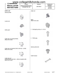
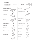
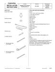
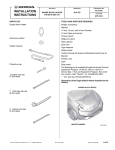
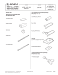
INSTALLATION
INSTRUCTIONS
Accessory
Application
STEERING WHEEL
P/N 08U97-TZ3-200
2015 TLX
PARTS LIST
Publications No.
VERSION 1
Issue Date
JULY 2014
Illustration of the Steering Wheel in the Vehicle
Steering wheel
2
TORX bolts
Steering wheel bolt
STEERING
WHEEL
QC02801AB
INSTALLATION
Client Information: The information in this installation
instruction is intended for use only by skilled
technicians who have the proper tools, equipment, and
training to correctly and safely add equipment to your
vehicle. These procedures should not be attempted by
“do-it-yourselfers.”
Information
TOOLS AND SUPPLIES REQUIRED
Phillips screwdriver
10 mm Open end wrench
10 mm Hex bit
Ratchet
T30 TORX bit
Torque wrench
Steering wheel puller
HDS/MVCI
Shop towel
The following tools are available through the Honda Tool
and Equipment Program. On the iN, click on: Service >
Service Bay > Tool and Equipment Program, then enter
the number under “Search.” Or, call 888-424-6857.
• Plastic Trim Tool (T/N SILTRIMTL10)
• Trim Tool Set (T/N SOJATP2014)
© 2014 American Honda Motor Co., Inc. – All Rights Reserved.
NOTE:
• Observe all safety notes and precautions in the Service
Manual in addition to those in this Installation
Instruction.
• Do not damage the vehicle.
1. Turn the steering wheel so the front wheels are
pointing the straight ahead.
2. Disconnect the negative cable from the battery.
BII 51457 (1407)
08U97-TZ3-2000-90
1 of 7
3.
Remove the two TORX bolts.
4.
Unplug the two vehicle 2-pin connectors (pull up on
the locking tabs) and the vehicle 1-pin connector.
NOTE: Be careful not to damage the connectors.
2 VEHICLE
2-PIN CONNECTORS
VEHICLE
1-PIN
2 LOCKING
TABS
(Pull up.)
STEERING
WHEEL
2 TORX BOLTS
(Do not reuse.)
QC02802AB
AIRBAG
STEERING
WHEEL
QC02803BB
5.
2 of 7
BII 51457 (1407)
Remove the airbag. Do not drop the removed airbag
or hit it on an object. Place the removed airbag on a
pad surface with the top facing upward.
© 2014 American Honda Motor Co., Inc. – All Rights Reserved.
6.
With the front wheels pointing straight ahead unplug
the vehicle 20-pin connector from the cable reel, and
loosen the steering wheel bolt.
STEERING WHEEL
PULLER
9.
Remove the body cover.
STEERING
WHEEL
STEERING WHEEL BOLT
(Loosen.)
STEERING
WHEEL
PULLER
BOLT
2 RETAINING
TABS
VEHICLE
20-PIN
CONNECTOR
BODY COVER
2 SELFTAPPING
SCREWS
CABLE
REEL
2 PINS
CLIP
QC02805AB
STEERING
WHEEL BOLT
(Do not reuse
7.
8.
10. Remove the left and right paddle shifters from the
steering wheel.
STEERING
WHEEL
QC02804AB
4 SCREWS
Using a steering wheel puller, release the steering
wheel. Do not thread the steering wheel puller bolts
in more than 5 mm (0.2 in.). When removing the
steering wheel, take care not to move the front
wheels.
LEFT PADDLE
SHIFTER
RIGHT PADDLE
SHIFTER
STEERING
WHEEL
Remove the steering wheel bolt, then remove the
steering wheel.
VEHICLE
CONNECTORS
© 2014 American Honda Motor Co., Inc. – All Rights Reserved.
BII 51457 (1407)
QC02806AB
3 of 7
11. Remove the screw(s).
13. Remove the switch assembly and cable guide.
GROUND
TERMINAL
4 RETAINING
TABS
STEERING WHEEL
(Do not reuse
STEERING
WHEEL
SCREW
SCREW
(if equipped)
SWITCH ASSEMBLY
AND CABLE GUIDE
QC02807AB
14. Install the switch assembly and cable guide on the
new steering wheel.
12. Remove the self-tapping screws.
6 SELF-TAPPING
SCREWS
NEW STEERING
WHEEL
4 RETAINING
TABS
STEERING
WHEEL
4 of 7
QC02902AB
SWITCH ASSEMBLY
AND CABLE GUIDE
QC02901AB
BII 51457 (1407)
QC02903AB
© 2014 American Honda Motor Co., Inc. – All Rights Reserved.
15. Secure the switch assembly and cable guide to the
new steering wheel with the self-tapping screws.
17. Install the left and right paddle shifters.
4 SCREWS
6 SELFTAPPING
SCREWS
NEW STEERING
WHEEL
LEFT PADDLE
SHIFTER
RIGHT PADDLE
SHIFTER
NEW STEERING
WHEEL
SWITCH ASSEMBLY
AND CABLE GUIDE
16. Install the screw(s) and ground terminal.
NEW STEERING
WHEEL
VEHICLE
CONNECTORS
QC02904AB
QC02906AB
18. Plug the two connectors into the left and right paddle
shifters.
GROUND
TERMINAL
19. Install the body cover on the new steering wheel.
NEW STEERING
WHEEL
BODY COVER
SCREW
SCREW
(if equipped)
QC02905AB
2 SELFTAPPING
SCREWS
2PINS
© 2014 American Honda Motor Co., Inc. – All Rights Reserved.
BII 51457 (1407)
CLIP
QC02907AB
5 of 7
20. Before installing the steering wheel, make sure the
front wheels are pointing straight ahead, then center
the cable reel. Do this by first rotating the cable reel
clockwise until it stops, then rotate it
counterclockwise three full turns. The arrow mark on
the cable reel should point straight up.
Rotate clockwise
until it stops.
21. Install the new steering wheel on the steering
column shaft in the straight-ahead position:
• Route the two vehicle 2-pin connectors through
the opening in the new steering wheel.
• Plug the vehicle 20-pin connector to the cable
reel.
• Check that the wire harnesses are not pinched.
Rotate counterclockwise
about three full turns until
the arrow mark points up.
PIN
ARROW
MARK
STEERING
COLUMN SHAFT
NEW STEERING
WHEEL
2 VEHICLE
2-PIN
CONNECTORS
CABLE
REEL
NEW
STEERING
WHEEL
VEHICLE
20-PIN
CONNECTOR
NEW STEERING
WHEEL BOLT
Torque: 44-54 N·m
(4.5-5.5 kgf·m,
32-40 lbf·ft)
QC02908AB
QC02909AB
22. Install the new steering wheel bolt. Torque the
steering wheel bolt to 44-54 N·m (4.5-5.5 kgf·m,
32-40 lbf·ft).
6 of 7
BII 51457 (1407)
© 2014 American Honda Motor Co., Inc. – All Rights Reserved.
23. Install the airbag on the new steering wheel with two
new TORX bolts (plug-in the two vehicle 2-pin
connectors and one vehicle 1-pin connector).
• Alternately tighten the right and left TORX bolts
so that the gaps on the right and left sides
between the horn pad and the steering wheel
are even. Torque the TORX bolts to
6.9-11.8 N·m (0.7-1.2 kgf·m, 5.1-8.7 lbf·ft).
• TORX bolts are coated with non-hardening
thread lock sealant, so they cannot be reused.
When installing the steering wheel, be sure to
replace the TORX bolts with the ones included in
this kit.
2 VEHICLE 2-PIN
CONNECTORS
VEHICLE 1-PIN
CONNECTOR
NEW
STEERING
WHEEL
24. Check that all wire harnesses are routed properly
and all connectors are plugged in.
25. Reconnect the negative cable to the battery.
26. Reinstall all other removed parts.
27. Connect the HDS/MVCI, and clear the DTCs.
28. Inspect the following items. If any abnormality is
found, perform troubleshooting as described in the
Service Manual.
• Press the engine start/stop button to the ON
mode. The SRS indicator should come on for
about 6 seconds and then go off.
• Make sure the horn and steering wheel switches
work properly.
29. Press and hold the radio power button for two
seconds to restore the radio and navi (if equipped)
system functions.
30. Reset the clock on vehicles without navigation.
31. Restore the systems to normal operation as
described in the Service Manual if necessary.
32. Make sure the steering wheel is in the straight-ahead
position and that the front wheels are pointing
straight ahead if not, adjust the front toe as
described in the Service Manual.
2 NEW TORX
BOLTS
Torque:
6.9-11.8 N·m
(0.7-1.2 kgf·m,
5.1-8.7 lbf·ft)
AIRBAG
Make sure the clearances
are equal on both sides.
QC02910AB
HORN PAD
© 2014 American Honda Motor Co., Inc. – All Rights Reserved.
BII 51457 (1407)
7 of 7