1
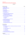
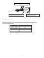
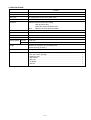
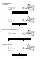
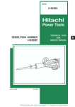
MODEL
H 65SC
POWER TOOLS
HAMMER
H 65SC
LIST No. E451
TECHNICAL DATA
AND
SERVICE MANUAL
Nov. 1999
SPECIFICATIONS AND PARTS ARE SUBJECT TO CHANGE FOR IMPROVEMENT
H
REMARK:
Throughout this TECHNICAL DATA AND SERVICE MANUAL, a symbol(s)
is(are) used in the place of company name(s) and model name(s) of our
competitor(s). The symbol(s) utilized here is(are) as follows:
Competitors
Symbols Utilized
Company Name
Model Name
C-1
MAKITA
HM1303
C-2
MAKITA
HM1500
Notice for use
Specifications and parts are subject to change for improvement.
Refer to Hitachi Power Tool Technical News for further information.
CONTENTS
[ Business Section ]
Page
1. PRODUCT NAME
• • • • • • • • • • • • • • • • • • • • • • • • • • • • • • • • • • • • • • • • • • • • • • • • • • • • • • • • • • • • • • • • • • • • • • • • • • • • • • • • • • • • • • • • • • • • • • • • • • • • • • • • • • • • • • • • • • • • • • • •
• • • • • • • • • • • • • • • • • • • • • • • • • • • • • • • • • • • • • • • • • • • • • • • • • • • • • • • • • • • • • • • • • • • • • • • • • • • • • • • • • • • • • • • • • • • • • • • • • • • • • • • • • • •
1
• • • • • • • • • • • • • • • • • • • • • • • • • • • • • • • • • • • • • • • • • • • • • • • • • • • • • • • • • • • • • • • • • • • • • • • • • • • • • • • • • • • • • • • • • • • • • • • • • • • • • • • • • • • • • • • • • • • • • • • • • • •
1
2. MARKETING OBJECTIVE
3. APPLICATIONS
4. SELLING POINTS
• • • • • • • • • • • • • • • • • • • • • • • • • • • • • • • • • • • • • • • • • • • • • • • • • • • • • • • • • • • • • • • • • • • • • • • • • • • • • • • • • • • • • • • • • • • • • • • • • • • • • • • • • • • • • • • • • • • • • •
4-1. Selling Point Descriptions
5. SPECIFICATIONS
1
• • • • • • • • • • • • • • • • • • • • • • • • • • • • • • • • • • • • • • • • • • • • • • • • • • • • • • • • • • • • • • • • • • • • • • • • • • • • • • • • • • • • • • • • • • • • • • • • • • • • • • •
2
• • • • • • • • • • • • • • • • • • • • • • • • • • • • • • • • • • • • • • • • • • • • • • • • • • • • • • • • • • • • • • • • • • • • • • • • • • • • • • • • • • • • • • • • • • • • • • • • • • • • • • • • • • • • • • • • • • • • • •
3
5-1. Optional Accessories
• • • • • • • • • • • • • • • • • • • • • • • • • • • • • • • • • • • • • • • • • • • • • • • • • • • • • • • • • • • • • • • • • • • • • • • • • • • • • • • • • • • • • • • • • • • • • • • • • • • • • • • • • • • • •
6. COMPARISONS WITH SIMILAR PRODUCTS
6-1. Specification Comparisons
4
• • • • • • • • • • • • • • • • • • • • • • • • • • • • • • • • • • • • • • • • • • • • • • • • • • • • • • • • • • • • • • • • • • • • • • • • • • • •
6
• • • • • • • • • • • • • • • • • • • • • • • • • • • • • • • • • • • • • • • • • • • • • • • • • • • • • • • • • • • • • • • • • • • • • • • • • • • • • • • • • • • • • • • • • • • • • • • • • • • • • •
6
6-2. Demolition Performance Comparisons
• • • • • • • • • • • • • • • • • • • • • • • • • • • • • • • • • • • • • • • • • • • • • • • • • • • • • • • • • • • • • • • • • • • • • • • • • • • • • • • • • • • •
6
• • • • • • • • • • • • • • • • • • • • • • • • • • • • • • • • • • • • • • • • • • • • • • • • • • • • • • • • • • • • • • • • • • • • • • • • • • • • • • • • • • • •
7
• • • • • • • • • • • • • • • • • • • • • • • • • • • • • • • • • • • • • • • • • • • • • • • • • • • • • • • • • • • • • • • • • • • • • • • • • • • • • • • • • • • • • • • • • • • • • • • • • • • • • • • • • • • • •
7
• • • • • • • • • • • • • • • • • • • • • • • • • • • • • • • • • • • • • • • • • • • • • • • • • • • • • • • • • • • • • • • • • • • • • • • • • • • • • • • • • • • • • • • • • • • • • • • • • • • • • • • • • • • • • • • • • • • • • • • • •
7
• • • • • • • • • • • • • • • • • • • • • • • • • • • • • • • • • • • • • • • • • • • • • • • • • • • • • • • • • • • • • • • • • • • • • • • • • • • • • • • • • • • • • • • • • • • • • • • • • • • • • • • • • • • • • • • • • • • • • • • • • • • • • •
7
7. PRECAUTIONS IN SALES PROMOTION
7-1. Handling Instructions
7-2. Caution Plate
7-3. Oil Supply
1
• • • • • • • • • • • • • • • • • • • • • • • • • • • • • • • • • • • • • • • • • • • • • • • • • • • • • • • • • • • • • • • • • • • • • • • • • • • • • • •
7-4. Impact Performance at Low Temperatures
8
8. REFERENCE INFORMATION
• • • • • • • • • • • • • • • • • • • • • • • • • • • • • • • • • • • • • • • • • • • • • • • • • • • • • • • • • • • • • • • • • • • • • • • • • • • • • • • • • • • • • • • • • • • • • • • • • • • • • •
9
8-1. Structure of the Main Body
• • • • • • • • • • • • • • • • • • • • • • • • • • • • • • • • • • • • • • • • • • • • • • • • • • • • • • • • • • • • • • • • • • • • • • • • • • • • • • • • • • • • • • • • • • • • • • • • • • • • •
9
• • • • • • • • • • • • • • • • • • • • • • • • • • • • • • • • • • • • • • • • • • • • • • • • • • • • • • • • • • • • • • • • • • • • • • • • • • • • • • • • • • • • • • • • • • • • • • • • • • • • • • •
9
8-2. Stop Lever [Tool Retainer]
8-3. Movement of the Stop Lever
••••••••••••••••••••••••••••••••••••••••••••••••••••••••••••••••••••••••••••••••••••••••••••••••••
8-4. No-load Striking Preventive Mechanism
10
• • • • • • • • • • • • • • • • • • • • • • • • • • • • • • • • • • • • • • • • • • • • • • • • • • • • • • • • • • • • • • • • • • • • • • • • • • • • • • • • • • •
10
• • • • • • • • • • • • • • • • • • • • • • • • • • • • • • • • • • • • • • • • • • • • • • • • • • • • • • • • • • • • • • • • • • • • • • • • • • • • • • • • • • • • • • • • • • • • • • • • • • • • • • • • • • • • • • • • • • • • • • • • • • • •
10
[ Service Section ]
9. REPAIR GUIDE
9-1. Precautions and Suggestions for Disassembly and Reassembly of the Main Body
• • • • • • • • • • • • • • • • • • • • •
10
9-1-1. Disassembly
• • • • • • • • • • • • • • • • • • • • • • • • • • • • • • • • • • • • • • • • • • • • • • • • • • • • • • • • • • • • • • • • • • • • • • • • • • • • • • • • • • • • • • • • • • • • • • • • • • • • • • • • • • • • • • • • • • • • •
10
9-1-2. Reassembly
••••••••••••••••••••••••••••••••••••••••••••••••••••••••••••••••••••••••••••••••••••••••••••••••••••••••••••••••••••••
13
9-1-3. Screw Locking Agent TB1401
••••••••••••••••••••••••••••••••••••••••••••••••••••••••••••••••••••••••••••••••••••••••••••
16
• • • • • • • • • • • • • • • • • • • • • • • • • • • • • • • • • • • • • • • • • • • • • • • • • • • • • • • • • • • • • • • • • • • • • • • • • • • • • • • • • • • • • • • • • • • • • • • • • • • • • • • • • • • • •
16
••••••••••••••••••••••••••••••••••••••••••••••••••••••••••••••••••••••••••••••••••••••••••••••••••••••••••••••••••
16
9-1-4. Tightening Torque
9-1-5. Internal Wiring
9-1-6. Insulation Tests
• • • • • • • • • • • • • • • • • • • • • • • • • • • • • • • • • • • • • • • • • • • • • • • • • • • • • • • • • • • • • • • • • • • • • • • • • • • • • • • • • • • • • • • • • • • • • • • • • • • • • • • • • • • • • • • • •
9-1-7. No-Load Current Value
• • • • • • • • • • • • • • • • • • • • • • • • • • • • • • • • • • • • • • • • • • • • • • • • • • • • • • • • • • • • • • • • • • • • • • • • • • • • • • • • • • • • • • • • • • • • • • • • • • • • • •
10. STANDARD REPAIR TIME (UNIT) SCHEDULES
17
17
• • • • • • • • • • • • • • • • • • • • • • • • • • • • • • • • • • • • • • • • • • • • • • • • • • • • • • • • • • • • • • • • • • • • • •
18
••••••••••••••••••••••••••••••••••••••••••••••••••••••••••••••••••••••••••••••••••••••••••••••••••••••
19
[ Appendix ]
Assembly Diagram for H 65SC
1. PRODUCT NAME
Hitachi Electric Hammer, Model H 65SC
2. MARKETING OBJECTIVE
The Model H 65SC is a double-insulated version of the existing single-insulated Model PH-65A. It has a
recirculating lubricating system. Demolishing and chipping power is comparable to that of the PH-65A, as is the
basic structure. The main features of the Model H 65SC is as follows:
(1) Highest demolition performance in this class.
(2) Durable, Aluminum-die-cast Housing for longer service life.
(3) Lower consumption motor design.
3. APPLICATIONS
Demolishing of concrete and similar materials.
Groove and channel digging in concrete.
Groove and channel digging in asphalt and gravel roads.
Tamping/compacting of asphalt and graveled roads.
Cutting of asphalt.
[Typical Applications]
Constructions work, piping/wiring work, water supply/drain work, etc.
4. SELLING POINTS
Maker • Model
Weight
Overall length
HITACHI
H 65SC
15 kg (33.1 lbs.)
647 mm (25-15/32")
HITACHI
PH-65A
15 kg (33.1 lbs.)
642 mm (25-9/32")
C-1
14 kg (30.9 lbs.)
675 mm (26-37/64")
C-2
17 kg (37.5 lbs.)
647 mm (25-15/32")
--- 1 ---
Largest demolition performance in this class.
Internal double-insulation construction
with rugged aluminum frame.
Automatic lubricator permits operating over
extended periods without supplying oil.
4-1. Selling Point Descriptions
4-1-1. Largest demolition performance in this class
Demolition performance is 1.1 to 1.3 times larger than that of similar products thanks to the maximum 39.5 J
impact energy and efficient striking.
Maker • Model
Ratio of demolished weight (%)
HITACHI
H 65SC
100
HITACHI
PH-65A
100
C-1
80
C-2
92
--- 2 ---
5. SPECIFICATIONS
Item
H 65SC
Power source
Single-phase AC 50/60 Hz
Voltage (V)
110, 115, 230, 240
Motor type
AC single-phase series commutator motor
Insulation structure
Double insulation
Enclosure
Materials: Aluminum alloy die casting
Cast aluminum alloy
Glass-fiber reinforced plastic resin
Paint:
Hammer-net silver green and black
Switch
Trigger switch (with stopper)
Type of handles
D-shaped handle and side handle
Full-load current
11.8 A (110 V), 11.4 A (115 V), 5.7 A (230 V), 5.4 A (240 V)
Power input
1,240 W
Striking speed No-load
1,800 /min.
Full-load
Weight
1,400 /min.
Product: 15.0 kg (33.1 lbs.); excluding cord
Packed: 23.5 kg (51.8 lbs.)
Packaging
Standard accessories
Corrugated cardboard box with steel tool case
Hex. bar wrench (for M6)
Hex. bar wrench (for M8)
Steel tool case
Side handle
Bull point
Oil feeder
Wrench
• • • • • • • • • • • • • • • • • • • • • • • • • • • • • • • • • • • • • • • • • • • • • • • • • • • • • • • • • • • • • • • • • • • • • • • • • • • •
• • • • • • • • • • • • • • • • • • • • • • • • • • • • • • • • • • • • • • • • • • • • • • • • • • • • • • • • • • • • • • • • • • • • • • • • • • • •
• • • • • • • • • • • • • • • • • • • • • • • • • • • • • • • • • • • • • • • • • • • • • • • • • • • • • • • • • • • • • • • • • • • • • • • • • • • • • • • • • • • • • • • • • • •
••• • • • • • • • • • • • • • • • • • • • • • • • • • • • • • • • • • • • • • • • • • • • • • • • • • • • • • • • • • • • • • • • • • • • • • • • • • • • • • • • • • • • • • • • • • • • •
•••••• • • • • • • • • • • • • • • • • • • • • • • • • • • • • • • • • • • • • • • • • • • • • • • • • • • • • • • • • • • • • • • • • • • • • • • • • • • • • • • • • • • • • • • • • • • • •
• • • • • • • • • • • • • • • • • • • • • • • • • • • • • • • • • • • • • • • • • • • • • • • • • • • • • • • • • • • • • • • • • • • • • • • • • • • • • • • • • • • • • • • • • • • • • • • • • •
•••••••• • • • • • • • • • • • • • • • • • • • • • • • • • • • • • • • • • • • • • • • • • • • • • • • • • • • • • • • • • • • • • • • • • • • • • • • • • • • • • • • • • • • • • • • • • • • • •
--- 3 ---
1
1
1
1
1
1
1
5-1. Optional Accessories
1. Demolition work
+
(1) Bull point
Overall length
Code No.
410 mm (16-9/64")
944961
2. Grooving and chiseling work
+
(1) Cold chisel
Overall length
Code No.
410 mm (16-9/64")
944962
3. Cutting and stripping work (asphalt cutting, etc.)
+
(1) Cutter
Width
Overall length
Code No.
75 mm (2-61/64")
410 mm (16-9/64")
944964
4. Digging (substitute pick-ax)
+
(1) Scoop
Overall length
Code No.
550 mm (21-21/32")
944967
--- 4 ---
5. Tamping work
+
(1) Rammer
Code No. 944965
Ext. Dia. 200 mm dia.
(7-7/8")
+
(2) Shank (SDS-max shank type)
Overall length
250 mm (9-27/32")
Code No.
944966
6. Electric hammer oil
Capacity
Code No.
1 liter (0.26 gallon)
955009
(Note)
Code numbers listed above are subject to change. Please refer to periodic Technical News Bulletins.
--- 5 ---
6. COMPARISONS WITH SIMILAR PRODUCTS
6-1. Specification Comparisons
Maker
HITACHI
C-1
C-2
1,240
1,300
1,430
1,400
1,400
1,450
1,300
mm
647
(25-15/32")
642
(25-9/32")
675
(26-37/64")
647
(25-15/32")
Height
mm
235
(9-1/4")
231
(9-3/32")
212
(8-11/32")
215
(8-15/32")
Width
mm
120
(4-23/32")
120
(4-23/32")
120
(4-23/32")
--(---)
Striking energy per stroke
J
39.5
39.5
39.5
40.3
Insulation structure
---
Double
insulation
Single
insulation
Double
insulation
Double
insulation
No-load noise level
dB(A)
92
92
94
93
kg
15.0
(33.1 lbs.)
15.0
(33.1 lbs.)
14.0
(30.9 lbs.)
17.0
(37.5 lbs.)
Model name
H 65SC
PH-65A
W
1,240
/min
Length
Power input
Full-load impact rate
Dimensions
Weight (without cord)
6-2. Demolition Performance Comparisons
The data shown in Fig. 1 are obtained in actual factory tests, and are for reference only. Demolished amount may
vary in accordance with operating conditions, operator skill, etc.
Demolished weight
for 30 min. (kg)
75
100
125
At rated
voltage
C-1
Demolished amount
150
175 (kg/30 min.)
H65SC
178
PH-65A
178
142
C-2
Fig. 1
--- 6 ---
164
7. PRECAUTIONS IN SALES PROMOTION
In the interest of promoting the safest and most efficient use of the Model H 65SC Electric Hammer by all of our
customers, it is very important that at the time of sale the salesperson carefully ensures that the buyer seriously
recognizes the importance of the contents of the Handling Instructions, and fully understands the meaning of the
precautions listed on the Caution Plate attached to each tool.
7-1. Handling Instructions
Although every effort is made in each step of design, manufacture and inspection to provide protection against
safety hazards, the dangers inherent in the use of any electric tool cannot be completely eliminated. Accordingly,
general precautions and suggestions for the use of electric power tools, and specific precautions and suggestions
for the use of the Electric Hammer are listed in the Handling Instructions to enhance the safe, efficient use of the
tool by the customer. Salespersons must be thoroughly familiar with the contents of the Handling Instructions to
be able to offer appropriate guidance to the customer during sales promotion.
7-2. Caution Plate
Each Model H 65SC unit is provided with a Caution Plate (illustrated below) which lists basic safety precautions in
its use. Carefully ensure that the customer fully understands and follows these precautions before using the tool.
For the U.S.A. and Canada
Hitachi Koki
-- WARNING --
To reduce the
risk of injury,
user must read and understand instruction manual.
AVERTISSEMENT Afin de rèduire le risque de
blessures, l'utilisateur doit lire et
bien comprendre le mode d'emploi.
Cautions on Oil Gauge:
If lubricant for high-speed rotating and sliding parts
OIL GAUGE CAP
Feed oil, before oil is invisible
in the oil gauge by holding the
body upright.
such as the needle bearings, piston, etc. is depleted,
it could cause damage such as jamming of sliding
parts, early damage, etc.
7-3. Oil Supply
As the Model H 65SC is equipped with a built-in oil tank, there is no need for manual oiling of the tool prior to and
during operation.
To prevent possible oil staining of the steel carrying case during shipping, only approximately 10 cc of oil is
supplied to the oil tank when the tool is shipped from the factory. Accordingly, it is very important that the
customer be instructed to remove the Oil Gauge and fill the oil tank with the standard accessory oil at the
time of purchase.
--- 7 ---
Instruct the customer to check the amount of oil periodically by holding the tool upright, as illustrated below, and
observing the oil level in the Oil Gauge. When the oil level drops to a point approximately 3 mm (7/64") or less
from the bottom of the Oil Gauge, remove the Oil Gauge and replenish the oil.
Oil Gauge
3 mm (7/64")
Hold the tool
upright, and
check the amount
of oil.
Replenish oil when level
is approx. 3 mm (7/64") or less
from bottom of Oil Gauge.
Fig. 2
Under average operating conditions, approximately 3 cc of oil will be consumed per hour of operation. The
standard accessory oil feeder contains 120 cc of oil; when it is added to the oil tank, the oil tank will be filled with
approximately 130 cc of oil. When it becomes necessary to replenish the oil, the customer should be cautioned to
use Shell Omala Oil #150 without fail. To ensure that the appropriate oil is used, the customers should be urged
to purchase and use the optional accessory Hitachi Electric Hammer Oil, Code No. 955009, which is available in
one liter (0.26 gallon) containers.
7-4. Impact Performance at Low Temperatures
When starting the tool early in the morning when the ambient temperature is low or after the tool has not been
used for a long period of time, oil viscosity may be very high and may cause improper or even complete lack of
impact function even though the motor functions properly. In such a case, the customer should be instructed to
continue no-load operation for approximately 5 minutes to allow the tool to warm up. The tool should then
function normally.
--- 8 ---
8. REFERENCE INFORMATION
8-1. Structure of the Main Body
The primary structure of the Model H 65SC is similar with the Model PH-65A, as illustrated. (Fig. 3)
Gear Cover Ass'y
Front Cover
Inner Cover
Striker
Stop Lever
Shank Sleeve
L Ring
Mouth
Cylinder Case
Crank Shaft
Final Gear
Piston Pin
Piston
Counter Gear
Switch Handle
Connecting Rod
Housing Ass'y
Felt Holder (C)
Ass'y
Stator Ass'y
Armature Ass'y
Fig. 3
8-2. Stop Lever [Tool Retainer] (Fig. 4 and Fig. 5)
Front Cover
(1) Clean, then smear the tool shank with
grease or machine oil. (Fig. 4)
(2) Rotate the stop lever 180˚ in a
Hold the tool with its flattened
part directed upward.
2
clockwise direction while pulling it
toward you. Next, insert the tool shank
into the hexagonal hole on the front
3
Stop Lever
Tool Shank
cover. (Fig. 4)
(3) Clamp the tool by turning the stop lever
1
Fig. 4
by half a turn in the opposite direction.
(Fig. 5)
Stop Lever
Fig. 5
--- 9 ---
8-3. Movement of the Stop Lever
After an extended period of use, the operation of the Stop Lever may become difficult due to incursion of concrete
powder or similar materials into its sliding portion. In such a case, apply oil into the sliding portion between the
Stop Lever and fitting portion of the Front Cover.
8-4. No-load Striking Preventive Mechanism
This machine is so constructed that when the bit end is lifted off the surface being worked, the striker is caught in
the mouth to prevent no-load striking; and when the striker comes off the mouth, a phase difference between the
piston and striker is utilized to reduce the striker's amplitude, thereby preventing the striker from striking the bit as
a double-preventive measure against no-load striking. When the striker is prevented from striking the bit, turn the
switch OFF; then the switch ON again with the bit lightly push the main body on the concrete surface so that the
equipment starts striking.
9. REPAIR GUIDE
9-1. Precautions and Suggestions for Disassembly and Reassembly of the Main Body
The [Bold] numbers in the descriptions below correspond to the item numbers in the Parts List and exploded
assembly diagram.
9-1-1. Disassembly
[NOTE] If it is difficult to loosen and remove the fixing bolts, use an appropriate heat gun, etc. to heat them to
approximately 80 ˚C (176 ˚F).
Disassembly of the Armature Ass'y [61]
(1) Loosen the four Seal Lock Hex. Socket Hd. Bolts M4 x 12 [70], remove the Cap Covers [65], Cap Rubbers
[66] and Brush Caps [67], and take out the Carbon Brushes [68]. At this time, be very careful not to lose the
disassembled parts.
(2) Loosen the four Nylock Hex. Socket Hd. Bolts M8 x 35 [22], and remove the Cylinder Case [20]. Next, after
loosening the Seal Lock Hex. Socket Hd. Bolt M8 x 16 [35], the Connecting Rod Ass'y [38] and Crank Washer
[39] can be disassembled. Leave the Striker [8] and Piston [11] as they are.
(3) Loosen the four Seal Lock Hex. Socket Hd. Bolts M6 x 25 [101], and take off the Handle and Handle Cover
Set [88]. Next, loosen the six Seal Lock Hex. Socket Hd. Bolts M6 x 45 [47], and disassemble the Gear Cover
[40] and Counter Gear [52]. Then, by inserting a flat-blade screwdriver or similar tool into one of the air vents
of the Inner Cover [45] and lifting it upwards, the Inner Cover [45], Armature Ass'y [61], Crank Shaft [37], and
related parts can be removed in a single body.
(4) As illustrated in Fig. 6, support the Inner Cover [45] with an appropriate tubular jig, and push down on the end
surface of the armature shaft with a hand press to separate the Armature Ass'y [61] from the Inner Cover [45].
--- 10 ---
Press the end surface of the armature
with a hand press.
Inner Cover [45]
Crank Shaft [37]
Armature Ass'y [61]
Tubular jig
Fig. 6
Disassembly of the Crank Shaft [37] section
First, remove the four Seal Lock Hex. Socket Hd. Bolts M5 x 16 [33] which fix the Bearing Cover [32]. Then, as
illustrated in Fig. 7, support the lower surface of the Inner Cover [45] with an appropriate tubular jig, align an
appropriate steel rod with the end surface of the Crank Shaft [37], and press down on the steel rod with a hand
press. The Ball Bearing 6205DDCMPS2L [31], Distance Ring (B) [43], Final Gear [42], two Woodruff Keys 4 x 16
[36], and Crank Shaft [37] can then be disassembled from the Inner Cover [45].
Press the end surface of the crank shaft
by fitting a steel rod with a hand press.
Ball Bearing [41]
Final Gear [42]
Inner Cover [45]
Crank Shaft [37]
Tubular Jig
Fig. 7
Disassembly of remaining parts from the Inner Cover [45]
Loosen the three Seal Lock Hex. Socket Hd. Bolts M5 x 16 [33], and take out Bearing Cover (A) [48] and the
Ball Bearing 6203DDCMPS2L [49].
Disassembly of the Mouth [17] and related parts
First, remove the six Nylock Hex. Socket Hd. Bolts M8 x 30 [3], and separate the Front Cover [7] from the
Cylinder Case [20]. The Shank Sleeve [15], Damper [13], Mouth [17], Mouth Cover [16], Mouth Washer [18],
and Urethane Ring [19] can then be taken out.
Removal of the O-Ring [14]
As the O-Ring [14] is installed in the inner portion of the Shank Sleeve [15], it may be difficult to remove. As
illustrated in Fig. 8, pry the O-Ring [14] upward gently with a slender flat-blade screwdriver, being very careful
not to damage the surface of the O-Ring.
--- 11 ---
Removal of the Striker [8] and related parts
Remove the four Nylock Hex. Socket Hd. Bolts M8 x
O-Ring [14]
35 [22], and separate the Cylinder Case [20] from the
Housing Ass'y [59]. From the Cylinder Case [20],
Slender screwdriver
Shank
Sleeve [15]
take out the Striker [8], Piston [11], and Connecting
Rod Ass'y [38] in a single body. Holding the Striker
[8] firmly in one hand, grasp the Connecting Rod
Ass'y [38] in the other hand and pull it forcefully to
separate it from the Striker. Finally, extract the Piston
Pin [10] from the Piston [11], and separate the Piston
Fig. 8
from the Connecting Rod Ass'y [38].
Disassembly of the Stop Lever [1]
Lever Spring [5]
Stop Lever [1]
Damper (B) [6]
Needle Roller [2]
Spring
Case [4]
3 mm dia. hole
Steel rod
(3 mm or less dia.)
Push Damper (B) [6]
with two flat-blade screwdrivers.
Overlap the end surface of the
Stop Lever [1] on the flange
portion of the Front Cover [7].
Fig. 9
Disassembly procedures are illustrated in Fig. 9. Pull the Stop Lever [1] outward in the direction indicated by the
arrow, and turn it slightly so that its end surface comes to rest on the flange portion of the Front Cover [7]. Next,
turn the Spring Case [4] so that the holes of the Spring Case are aligned with the Needle Roller [2]. Then, push
in Damper (B) [6] with flat-blade screwdrivers to compress the Lever Spring [5]. Finally, while keeping the Lever
Spring compressed, fit a 3 mm or less dia. steel rod into the hole of the Spring Case [4], and push out the Needle
Roller [2]. The Stop Lever [1], the Damper (B) [6], and the Lever Spring [5] can then be taken out.
How to remove the L-Ring [9]
The L-Ring [9] can be removed by prying it with a flat-blade screwdriver or manually, as shown in the following
figure. (Fig. 10)
Fig. 10
--- 12 ---
9-1-2. Reassembly
Reassembly can be accomplished by following the disassembly procedures in reverse. However, special
attention should be given to the following items.
(1) Reassembly of the Crank Shaft [37] section:
Press-fit the Ball Bearing 6205DDCMPS2L [31] into the Inner Cover [45], and fasten Bearing Cover [32] onto
the Inner Cover [45] with the four Seal Lock Hex. Socket Hd. Bolts M5 x 16 [33]. Support the inner race of the
Ball Bearing 6205DDCMPS2L [31] with an appropriate jig, and press-fit the Crank Shaft [37] into the Ball
Bearing. Next, insert Distance Ring (B) [43] and two Woodruff Keys 4 x 16 [36] into the Crank Shaft [37], and
press-fit the Final Gear [42] and the Ball Bearing 6302VVCMPS2L [41] with a hand press.
(2) Reassembly of the Armature Ass'y [61]:
Press-fit the Ball Bearing 6203DDCMPS2L [49] into the Inner Cover [45], and fasten Bearing Cover (A) [48]
onto the Inner Cover with the three Seal Lock Hex. Socket Hd. Bolts M5 x 16 [33].
(3) Reassembly of the Striker [8]: (Two possible methods) (Fig. 11)
A. After the Connecting Rod Ass'y [38] has been
B. Mount the Piston [11] onto the Connecting
assembled into the Housing Ass'y [59], mount
Rod Ass'y [38], and push down on the
the Piston [11] and press it into the Striker [8].
Connecting Rod Ass'y to press the Piston into
the Striker [8].
Housing Ass'y [59]
Push
Push
Connecting Rod Ass'y [38]
Connecting Rod Ass'y [38]
Striker [8]
Piston [11]
Respiratory holes
Piston [11]
Striker [8]
Respiratory holes
Fig. 11
Either of the two methods described above requires a pressing force of more than 30 kg. When a "hissing" sound
is heard, the Piston is properly inserted in the Striker. (The "hissing" is the sound of the compressed air escaping
from the Striker when the Piston reaches the respiratory chambers within the Striker.)
--- 13 ---
(4) Reassembly of the Oil Felt:
To replace the Oil Felt [79], follow the procedures described below.
Slender-Tipped Rod
or Steel Wire
Oil Felt [79]
Oil Felt [79]
Protruding amount:
10 --- 11 mm (0.39" --- 0.43")
Recess
Felt Holder (C) Ass'y [77]
Fig. 12
Fig. 13
1) As illustrated in Fig. 12, fit the wide end of the Oil Felt [79] into the oiling hole, and push it through with a
slender-tipped rod or steel wire.
2) When approximately 5 mm (0.2") of the Oil Felt [79] has been pushed through into the oil tank, grasp the
tip with pliers or a similar tool, and pull it into the oil tank so that 10 --- 11 mm (0.39" --- 0.43") remains
protruding into the crank case chamber side, as illustrated in Figs. 12 and 13.
3) As illustrated in Fig. 14, mount the Felt Holder (C) Ass'y [77] so that its recess is engaged with the
protrusion on the inside of the oil tank chamber of the housing.
4) Assemble the Connecting Rod Ass'y [38] onto the Crank Shaft [37], rotate the Crank Shaft by hand, and
confirm that the Oil Felt [79] comes into contact with the Seal Lock Hex. Socket Hd. Bolt M8 x 16 [35]
which fixes the Connecting Rod Ass'y [38]. (Fig. 15)
5) After mounting the Felt Holder (C) Ass'y [77], the Oil Felt [79] must be bent toward the Front Cover [7]
side as illustrated in Fig. 15.
--- 14 ---
Oil Felt [79]
Recess
Protrusion
Connecting Rod Ass'y [38]
M8 x 16 Hex.
Bolt [35]
Front Cover
Housing
Ass'y
Felt Holder (C) Ass'y [77]
Oil Tank Chamber
Oil Felt [79]
Oil Tank Chamber
Fig. 15
Fig. 14
(5) How to install Seal Ring (A) [44]:
To prevent oil from leaking through between the Housing Ass'y [59] and the Inner Cover [45], Seal Ring (A)
[44] is installed in the Inner Cover [45] for sealing oil. When fitting Seal Ring (A) [44] in the ring groove on the
Inner Cover [45], exercise care not to allow the Seal Ring to twist or project out of the groove.
(6) How to install the L-Ring [9]:
When installing the L-Ring [9] on the Piston [11],
pay attention to the L-Ring direction. The longer
flange side should be directed to the front, as shown
in the figure. (Fig. 16)
Fig. 16
(7) Cover Plate [72]:
Any gap between the Cover Plate [72] and the Housing Ass'y [59] may result in oil leakage or failure of
automatic lubrication. Do not disassemble the Cover Plate [72] except when absolutely necessary. When it is
inevitably necessary to disassemble and reassemble the Cover Plate (as when replacing the Oil Felt [79]), for
thorough sealing, apply liquid packing (Fuji Oil Sheet No. 600K) to the mounting surface on the Housing Ass'y
[59].
--- 15 ---
9-1-3. Screw Locking Agent TB1401
(1) Prior to reassembly, all M5, M6, Hexagon Socket Hd. Bolts and Machine Screws must be coated with Screw
Locking Agent ThreeBond TB1401.
(2) The following parts must be replaced with Hitachi Genuine Parts once they are loosened.
Front Cover Fixing Bolts:
M8 x 30 [3]
Cylinder Case Fixing Bolts:
M8 x 35 [22]
Fixing Bolt on the Connecting Rod Ass'y [38]
M8 x 16 [35]
(CAUTION)
If fastening bolts come loose from vibration, it could cause serious damage to the machine.
Ensure without fail that TB1401 Screw Locking Agent is applied as directed above prior to
reassembly.
Before applying the TB1401, carefully clean any grease or other foreign matter from the male
and female threads with gasoline, thinner or similar cleaning solvents.
9-1-4. Tightening Torque
(1) M4 Hexagon Socket Hd. Bolts
4.41
0.49
7.84
+1.96
0
9.80
+1.96
0
(4) M8 Hexagon Socket Hd. Bolts
29.4
+1.96
0
(5) D4 Tapping Screw
1.96
0.49
(2) M5 Hexagon Socket Hd. Bolts
(3) M6 Hexagon Socket Hd. Bolts
5
N•m (45
N•m (80
+20
0
kgf•cm, 69.5
N•m (100
+20
0
N•m (300
+20
0
N•m (20
5
4.3
kgf•cm, 39.1
kgf•cm, 86.9
kgf•cm, 260
kgf•cm, 17.4
in-Ibs.)
+12.4
0
in-Ibs.)
+17.4
0
+17.4
0
+4.3
0
in-Ibs.)
in-Ibs.)
in-Ibs.)
[NOTE] If above bolts are tightened more than the designated values, it may cause breakage. Without fail,
tighten the Bolts and Screws according to the above specified values.
9-1-5. Internal Wiring
Wiring diagram of products with noise suppressor (Fig. 17)
Switch
Stator
Connector
Tube
Brown
Tube
Plug
Connector
Armature
Noise
Suppressor
Blue
Stator
Pillar Terminal
Fig. 17
--- 16 ---
Wiring diagram of products without noise suppressor (Fig. 18)
Switch
Stator
Tube
Black
Tube
Plug
Armature
White
Tube
Stator
Pillar Terminal
Fig. 18
9-1-6. Insulation Tests
On completion of disassembly and repair, measure the insulation resistance and dielectric strength.
Insulation resistance: 7 MΩ or more with DC 500 V Megohm Tester.
Dielectric strength:
AC 4000 V/1 minute, with no abnormalities
• • •
220 V --- 240 V
(and 110 V for U.K. products)
AC 2500 V/1 minute, with no abnormalities
• • •
110 V --- 127 V
(except U.K. products)
9-1-7. No-Load Current Value
After no-load operation for 30 minutes, the no-load current value should be as follows:
Voltage (V)
110
115
220
230
240
Current (A) (Max.)
5.9
5.7
3.0
2.8
2.7
--- 17 ---
10. STANDARD REPAIR TIME (UNIT) SCHEDULES
MODEL
Variable
Fixed
20
40
60
80
100
120 min.
Work Flow
H 65SC
Housing
Stator Ass'y
Switch
Cord Ass'y
General Assembly
Handle
Gear Cover
Armature Ass'y
Fixed Cost
Switch
Handle
Front Cover
Lever
0 min. Front Cover
Lever
Cord Ass'y
10 min.
Others
20 min.
Mouth
Cylinder Case
Ass'y
Mouth Cover
Urethane Ring
Shank Sleeve
Damper
Striker
Piston
L-Ring
Connecting
Rod Ass'y
Needle
Bearing
--- 18 ---
Ball Bearing
(6201)
Ball Bearing
(6203)
Counter Gear
Ball Bearing
(6001)
Ball Bearing
(6201)
Ball Bearing
(6302)
Final Gear
Crank Shaft
Ball Bearing
(6205)
Inner Cover
Assembly Diagram for H 65SC
--- 19 ---
H 65SC
PARTS
ITEM
NO.
1
CODE NO.
DESCRIPTION
NO.
USED
1
998-423
STOP LEVER
2
998-426
NEEDLE ROLLER
1
3
306-437
NYLOCK HEX. SOCKET HD. BOLT M8X30
6
4
998-424
SPRING CASE
1
5
956-975
LEVER SPRING
1
6
998-425
DAMPER (B)
1
7
957-152
FRONT COVER
1
8
956-958
STRIKER
1
9
944-927
L-RING
1
10
944-928
PISTON PIN
1
11
956-957
PISTON
1
12
944-918
PIN D5X15.8
2
13
956-965
DAMPER
1
14
944-936
O-RING
1
15
956-964
SHANK SLEEVE
1
16
956-962
MOUTH COVER
1
17
956-963
MOUTH
1
18
956-961
MOUTH WASHER
1
19
956-960
URETHANE RING
1
20
306-164
CYLINDER CASE (BLACK)
1
21
956-996
O-RING (1AS-60)
1
22
306-163
NYLOCK HEX. SOCKET HD. BOLT M8X35
4
23
949-433
BOLT WASHER M8 (10 PCS.)
4
24
944-950
U-NUT (B) M8
2
25
944-948
HANDLE STAY
1
26
949-895
SPLIT PIN D4X25 (10 PCS.)
2
27
944-952
HANDLE SHAFT
1
28
949-655
HEX. SOCKET HD. BOLT M8X16 (10 PCS.)
2
29
956-852
SIDE HANDLE ASS’Y
1
30
944-951
GRIP
1
31
620-5DD
BALL BEARING 6205DDCMPS2L
1
32
956-949
BEARING COVER
1
33
990-079
SEAL LOCK HEX. SOCKET HD. BOLT M5X16
7
34
944-921
NEEDLE BEARING (NTN 8E-NK 18/20 RDO)
1
35
996-364
SEAL LOCK HEX. SOCKET HD. BOLT M8X16
1
36
956-850
WOODRUFF KEY 4X16
2
37
957-142
CRANK SHAFT
1
38
998-434
CONNECTING ROD ASS’Y
1
39
956-955
CRANK WASHER
1
40
318-207
GEAR COVER
1
41
630-2VV
BALL BEARING 6302VVCMPS2L
1
42
944-916
FINAL GEAR
1
43
944-915
DISTANCE RING (B)
1
44
957-143
SEAL RING (A)
1
45
998-412
INNER COVER
1
NAME PLATE
1
46
47
986-940
SEAL LOCK HEX. SOCKET HD. BOLT M6X45
6
48
944-911
BEARING COVER (A)
1
49
620-3DD
BALL BEARING 6203DDCMPS2L
1
50
944-907
DISTANCE RING (A)
1
51
620-1VV
BALL BEARING 6201VVCMPS2L
1
8 --- 99
PARTS
* : ALTERNATIVE
--- 20 ---
REMARKS
INCLUD.24-28,30
INCLUD.34
H 65SC
PARTS
ITEM
NO.
52
CODE NO.
DESCRIPTION
NO.
USED
1
REMARKS
956-948
COUNTER GEAR
53
600-1VV
BALL BEARING 6001VVCMPS2L
1
54
960-251
HEX. HD. TAPPING SCREW D5X65
2
55
956-764
SPECIAL WASHER
2
*
56
340-259G
STATOR ASS’Y 115V
1
INCLUD.57,63 FOR USA
*
56
340-259E
STATOR ASS’Y 220V-230V
1
INCLUD.57,63
57
945-932
BRUSH TERMINAL
2
58
620-1DD
BALL BEARING 6201DDCMPS2L
1
59
318-208
HOUSING ASS’Y
1
60
996-370
FAN
1
*
61
360-286U
ARMATURE ASS’Y 115V
1
INCLUD.49,58,60,64 FOR USA
*
61
360-286E
ARMATURE ASS’Y 220V-230V
1
INCLUD.60
62
306-098
FAN GUIDE
1
VINYL TUBE(ID7XT0.25X20)
1
944-954
BEARING WASHER
1
63
64
65
956-972
CAP COVER
2
66
944-960
CAP RUBBER
2
67
940-540
BRUSH CAP
2
68
999-086
CARBON BRUSH (AUTO STOP TYPE) (1 PAIR)
2
69
956-984
BRUSH HOLDER
2
70
983-162
SEAL LOCK HEX. SOCKET HD. BOLT M4X12
4
71
956-971
COVER SEAL
1
72
956-970
COVER PLATE
1
73
991-690
SEAL LOCK HEX. SOCKET HD. BOLT M5X12
6
74
955-011
OIL GAUGE
1
CAUTION PLATE
1
75
76
956-969
HOLDER SEAL
1
77
318-206
FELT HOLDER (C) ASS’Y
1
INCLUD.69,80
INCLUD.79
78
987-203
SEAL LOCK SCREW (W/SP. WASHER) M4X12
4
79
998-534
OIL FELT
1
80
938-477
HEX. SOCKET SET SCREW M5X8
2
81
306-099
TAIL COVER
1
82
307-028
TAPPING SCREW (W/FLANGE) D4X25 (BLACK)
3
*
83
981-974
INTERNAL WIRE
1
EXCEPT USA
*
84
949-423
WASHER M4 (10 PCS.)
1
FOR SAF,HOL
85
995-398
SWITCH (A) (1P SCREW TYPE) W/LOCK
1
86
312-408
SUPPORT (F)
1
87
994-273
NOISE SUPPRESSOR
1
88
971-168
HANDLE AND HANDLE COVER SET
1
*
89
500-440Z
CORD
1
(CORD ARMOR D8.2) FOR HKG
*
89
500-454Z
CORD
1
(CORD ARMOR D10.7) FOR SAF
*
89
500-390Z
CORD
1
(CORD ARMOR D10.7) FOR HOL
*
89
500-434Z
CORD
1
(CORD ARMOR D8.2) FOR USA
*
89
500-457Z
CORD
1
(CORD ARMOR D8.2) FOR CHN
*
90
938-307
PILLAR TERMINAL
1
FOR USA
*
91
963-243
SUPPORT
1
FOR USA
92
306-167
TUBE (I.D.7XT1.1X15)
1
*
93
305-798
INTERNAL WIRE
1
EXCEPT HKG,USA
*
94
959-140
CONNECTOR 50091 (10 PCS.)
1
EXCEPT HKG,USA
*
95
959-141
CONNECTOR 50092 (10 PCS.)
1
EXCEPT USA
*
96
996-438
VINYL TUBE (A) (I.D.7XT0.5X50)
2
*
PARTS
* : ALTERNATIVE
--- 21 ---
EXCEPT HKG,USA
8 --- 99
H 65SC
PARTS
ITEM
NO.
*
96
CODE NO.
NO.
USED
3
FOR USA
DESCRIPTION
996-438
VINYL TUBE (A) (I.D.7XT0.5X50)
*
97
980-063
TERMINAL
*
97
992-810
TERMINAL
1
FOR HOL
*
97
930-804
TERMINAL M4.0 (10 PCS.)
1
FOR USA
98
984-750
TAPPING SCREW (W/FLANGE) D4X16
2
99
960-266
CORD CLIP
1
REMARKS
1
*
100
940-778
CORD ARMOR D10.7
1
*
100
958-049
CORD ARMOR D8.2
1
101
987-707
SEAL LOCK HEX. SOCKET HD. BOLT M6X25
4
STANDARD ACCESSORIES
ITEM
NO.
501
CODE NO.
NO.
USED
1
DESCRIPTION
314-170
CASE (STEEL)
502
872-422
HEX. BAR WRENCH 6MM
503
944-459
HEX. BAR WRENCH 5MM
1
504
944-961
BULL POINT 410MM
1
505
971-109
WRENCH 23MM
1
506
931-848
LUBRICANT OILER (120CC)
1
REMARKS
1
OPTIONAL ACCESSORIES
ITEM
NO.
CODE NO.
DESCRIPTION
NO.
USED
601
944-962
COLD CHISEL 410MM (HEX. SHANK TYPE)
1
602
944-964
CUTTER W75X45L (ROUND SHANK TYPE)
1
603
944-966
RAMMER SHANK (HAMMER)
1
604
944-965
RAMMER 200MM
1
605
957-154
SCOOP 380L (ROUND SHANK TYPE)
1
Printed in Japan
(990825 N)
8 --- 99
* : ALTERNATIVE PARTS
--- 22 ---
REMARKS