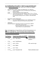
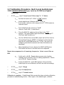
1
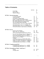
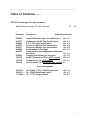
®
Service Manual
AudioScope™/ AudioScope 3™
Screening Audiometers
Single Hearing Level Models: 23020, 23000, 23040
Three Hearing Level Model 23300
Charging Stand 71123
Charging Transformers: Australia - 71036, Europe - 71032, Japan -71030,
United Kingdom 71034, United States - 71040
PN: 230260 Rev. B
Welch Allyn, Inc.
4341 State Street Road
P.O. Box 220
Skaneateles Falls, NY 13153-0220
Copyright 2004
__________________________________________________________________________
Revision History
ECN#/
ECO#
Date
Section
Title
Author
Description
5/31/96
1
General Info.
RJS
Intro of
Document
A
5/31/96
2
Service
RJS
Intro of
Document
A
5/31/96
3
Troubleshooting
RJS
Intro of
Document
A
5/31/96
4
Disassembly/Rep
air
RJS
Intro of
Document
A
5/31/96
5
Drawings/Specs.
RJS
Intro of
Document
B
6/17/04
Soldering
BSW
Added Soldering
Temperatures
Revision
5-32904
A
5-32904
5-32904
5-32904
5-32904
1001574
Drawings and/or illustrations and/or part numbers in
this document are for reference only. For the most
current revision call the Welch Allyn Customer Service
phone number listed in Section 1.
- 3 -
______________________________________________________________________________________
Table of Contents
Cover Page
Revision Page
Table of Contents
Sub Sect
SECTION 1: General Information
To Service Personnel
Limited Warranty
Introduction to AudioScopes
Figure 1.3 AudioScope Handle Controls
Basic System Description (Fig.1.4a Basic System)
Basic System Description (charging stand)
Use of the AudioScope (Screening)
Operating Program 1-Lev (Fig 1.6 Block Diagram)
Operating Program 3-Lev (s/n<=969999) ASIC
Operating Program 3-Lev (s/n>=970000)nonASIC
Technical Functional Specifications (All Models)
Pg.
1
3
4-5
1.1
1.2
1.3
1.3
1.4a
1.4b
1.5
1.6
1.7a
1.7b
1.8
7
8
9-11
11
12
12
13-14
15-17
18-20
21-22
23
2.1
2.2
2.3a
25
26
27-28
2.3b
29
2.3c
2.4
2.5
2.5
2.6
2.7
30
31
32-33
32
34-35
36-37
SECTION 3: Troubleshooting 23300
Troubleshooting AudioScope 3 s/n <=969999
Troubleshooting AudioScope 3 s/n >=970000
3.1
3.2
39
40
SECTION 4: Disassembly and Repair, AudioScope 3
Handle
Charging stand
4.1
4.2
43-45
46
SECTION 2: Service
Intent of Service Manual
Repair Parts for AudioScope
Lists of Tools/Fixtures/Documents for Service
Fig. 2.3b Tools/Fixtures Setup for Calibration for
AudioScope and AudioScope 3 s/n<=969999
Fig. 2.3c Tools/Fixtures Setup for Calibration for
AudioScope 3 s/n>=970000
Training
Calibration (Single Level 23020,23000,23040)
Figure 2.5.4 Sound Tube Placement/Adjustment
Calibration (Multi Level 23300) s/n <=969999
Calibration (Multi Level 23300) s/n >=970000
- 4 -
____________________________________________________________________________________
Table of Contents
conti nued
SECTION 5: Drawings/ Test Specifications
Manilla Pockets contain 17" x 22" drawings.
5.1
Drawing#
Description
A02030
A00277
A00984
A00273
A00273
A00985
A01825
Repair Calibration Spec. for AudioScope II
Audiometer Handle Test Specifications
P.C.B. Test Spec AudioScope II
Electronics Module Test Specification
Electronics Module Test Specification
Audio Module III Test Spec
AudioScope III Sound Equipment Calibration
and Setup
Charging Stand Electrical Test Spec.
Audio II Schematic (PCB for ASIC version)
PC Board Ass'y (for ASIC version
PCB Schematic (for Microcontroller version)
A00942
230230
230215
236630
49
Original Size/#sheets
B/1 of 1
D/1 of 1
D/1 of 1
D/1 of 2
D/2 of 2
D/1 of 1
C/1 of 1
A/1 of 1
D/1 of 1
D/1 of 1
B
Parts catalog pages
230137-3
230237-1
711408-2
Nos.23000, 23020, 23040 AudioScope
No. 23300 AudioScope II and 3
No. 71123 Charging Stand
A/1 of 1
A/1 of 1
A/1 of 1
- 5 -
Section 1:
General Information
____________________________________________________________________________________
1.1 To Service Personnel
Read and understand the AudioScope operating instructions manual pn. 2302312. The information in this Service Manual is subject to change without notice
and should not be construed as a commitment by Welch Allyn. Welch Allyn
assumes no responsibility for any errors that may appear in this manual.
Who to contact:
If the product and/or its operation varies significantly from any description
therein, please contact:
Welch Allyn Medical Products Division
Product Service Department,
4341 State Street Road, Skaneateles Falls, NY, 13153-0220, U.S.A.
Phone (315) 685-4445, or (800) 669-9771.
Fax
(315) 685-4653
This product has been designed to provide a high degree of safety and
reliability. However, we cannot guarantee against the deterioration of
components due to aging and normal wear.
All service and repairs must be done by authorized Welch Allyn personnel or
agents, using approved Welch Allyn replacement parts and approved process
materials. Failure to do so will invalidate the product warranty. Please refer
to the product warranty for specific coverage.
USING ADHESIVES: ALWAYS WEAR SAFETY GLASSES AND PROVIDE ADEQUATE
VENTILATION WHEN USING CA ADHESIVES, CA ACCELERATORS, AND RTV ADHESIVE
SEALANTS. READ AND OBEY WARNINGS, CAUTIONS, INSTRUCTIONS, AND
RECOMMENDATIONS PRINTED ON CONTAINER AND CORRESPONDING MSDS SHEETS
CAUTION: PRIOR TO DOING REPAIR WORK, UNPLUG POWER CORD ON CHARGER TO
ELIMINATE SHOCK HAZARD. USE GROUNDING MAT AND GROUNDING STRAP TO
REDUCE CHANCES OF DAMAGE TO ASIC IN HANDLE.
- 7 -
______________________________________________________________________
1.2 Limited Warranty
Welch Allyn warrants the AudioScope, when new, to be free of defects in
material and workmanship and to perform in accordance with the
manufacturer's specifications for a period of one year from the date of
purchase from Welch Allyn or its authorized distributors or agents.
Welch Allyn will either repair, replace or recalibrate any components (except
lamps) found to be defective or at variance from the manufacturer's
specifications within this time at no cost to the customer, except for
transportation expenses. For rechargeable batteries, warranty is extended to
two years. It shall be the purchaser's responsibility to return the instrument
directly to Welch Allyn or to an authorized distributor, agent or service
representative.
This warranty does not include breakage or failure due to tampering, misuse,
neglect, accidents, modification or shipping. This warranty is also void if the
instrument is not used in accordance with the manufacturer's recommendations
or if repaired by other than a Welch Allyn or authorized agent. This warranty
can be extended to a three-year period provided the instrument is returned for
recalibration annually. Submission of instrument registration card is required.
Purchase date determines warranty and recalibration requirements. No other
express warranty is given.
To receive service assistance or to ask questions regarding this warranty,
please call or write:
Welch Allyn Product Service Dept.
Welch Allyn, Inc.
Medical Products Division
4341 State Street Road
Skaneateles Falls, New York 13153 USA
1 (800) 669-9771 or (315) 685-4445
Note: The U.S. Occupational Safety and Health Administration (OSHA) recommends that audiometers
be calibrated annually. Arrangements for calibration can be made by returning the instrument
registration card. In addition a daily biological check may be performed. This is accomplished by a
person with known normal hearing who listens to the tones for intensity and quality. There is a
moderate fee for recalibration. *Re-printed from PN230108, Instrument Registration Card
- 8 -
___________________________________________________________________
1.3 Introduction to AudioScopes
The Welch Allyn AudioScope (audiometer) enables the practitioner to perform a
fast, painless and objective test for early hearing loss. The AudioScope3 starts
with a Practice Tone (PT) of 1,000 Hz at a dB HL dependent upon the selected
Screening dB HL.(Refer to Page 5 of Operating Instructions). After the Practice
Tone (PT), the AudioScope3 provides screening at all four speech frequencies:
1,000 Hz, 2,000 Hz, 4,000 Hz, and 500 Hz. This test can be performed at one
of three hearing levels: 20 dB, 25 dB, or 40 dB. Selection of the hearing level is
dependent on the age of the patient. Note: there is no PT with single level
AudioScopes. If a hearing problem is suspected, the patient is referred to a
specialist for diagnosis.
The AudioScope contains a 3.5-volt halogen lamp and otoscope lens for viewing
the tympanic membrane and the ear canal prior to and during hearing
screening.
There are two types of Welch Allyn AudioScopes in use today:
•
The first type is the single hearing level instrument of which there are three
models. Although they are obsolete, they can still be calibrated if they are
functioning according to specifications. Service parts are not available.
AudioScope pn 23020 - 20 dB (no PT)
AudioScope pn 23000 - 25 dB (no PT)
AudioScope pn 23040 - 40 dB (no PT)
•
The second type is the three hearing level (MultiLevel) AudioScope3. (Also
known as AudioScope II) There are two versions of this second type.
AudioScope3 pn 23300 - 20, 25, 40 dB (1000 Hz PT)
The original version of the AudioScope 3 (three hearing level) up to and
including serial number 969999 utilizes an ASIC module. This instrument is
calibrated by adjusting miniature potentiometers on the printed circuit board.
Although the main board/ASIC is being phased out at the time of this
writing, they can still be calibrated if they are functioning according to
specifications. Some parts are available. (See Repair Parts, Section 2.2)
NEW VERSION:
A new version (starting in 1996 with serial number 967000) differs from the
first AudioScope3 in that a Microcontroller is used instead of the ASIC.
Performance specifications of the new AudioScope 3 are identical to the earlier
AudioScope 3, and the part number remains the same. Since this version
utilizes a Microcontroller with digitally adjusted pots and not mechanical
potentiometers, calibration is much easier. Tool T-13765 is used to
electronically adjust the board. This advance eliminates the limitations of
mechanical potentiometers and reduces calibration time.
- 9 -
__________________________________________________________________________
1.3 Introduction to AudioScopes
The operation and calibration of all five of these screening audiometers are
explained in this manual.
Important note to Service Personnel
Board Replacement on AudioScope 3:
Welch Allyn manufactures only the AudioScope3 as of Oct. 1986. As of
1996, starting with serial no.967000 a new version AudioScope3 utilizes a
Microcontroller (does not have ASIC) and is calibrated using the T-13765
Calibrator Box. It has digital potentiometers for calibration, not mechanical
pots. All previous models were calibrated using mechanical potentiometer.
Calibration of all types of AudioScopes is explained in this manual. If the
ASIC fails on an AudioScope 3, the whole board will be replaced with the
new board containing the digitally adjustable Microcontroller. This board
will fit the AudioScope3 with no modifications. Unit performance is the
same.
Obsolescence of Single Level AudioScope:
Single Level AudioScopes are over ten years old. Service Parts are not
available. Recalibrations CAN be performed on properly functioning single
level AudioScopes. For failed units, save the lamp, battery, and charging
stand/transformer for use with AudioScope3.
- 10 -
____________________________________________________________________
1.3 Introduction to AudioScopes
AudioScope 3 Handle Controls and features are shown in the figure below.
- 11 -
____________________________________________________________________
1.4a Basic System Description
There are three components to the Welch Allyn AudioScope: the hand
held AudioScope handle, the Charger stand and transformer.
1.4b AudioScope Charging Stand
The charging stand holds the handle and specs and is the interface
between the Handle and the charging current of the wall transformer.
Insertion of the handle into the charging well completes the charging
circuit. An LED illuminates when the handle is in the well and the
charging circuit is complete.
_____________________________________________________________________
1.5 Use of the AudioScope (Screening)
Read pg. 6-8 of Operating Instructions pn230231-2 (shown below) for full
details of the screening procedure.
Note: The following excerpt is only an outline intended for general familiarization by
service personnel. This outline is not intended to replace above referenced Operating
Instructions pn 230231-2.
1.
Check that lens is centered in the instrument.
2.
Select an area that is relatively quiet and free from distracting sounds.
See page 26 of Operating Instructions for Maximum Permissible
Ambient Noise for the different screening levels.
3.
Select appropriate size specula and twist onto instrument. USE ONLY
GRAY-TIPPED WELCH ALLYN AUDIOSPECS.
- 13 -
_____________________________________________________________________
1.5 Use of the AudioScope (Screening) continued
4.
5.
6.
7.
Turn AudioScope3 "ON" by sliding the selection switch
to the
desired screening level.
Instruct patient to respond appropriately to sound. Insert the tip
of the speculum into the ear canal. Position the tip so that the
tympanic membrane or a portion of it can be visualized.
Depress START button and observe each tone and the patient's
response. Repeat these steps for opposite ear.
Remove instrument from patient's ear and turn off. Return to the
Charging stand. (REFER TO Operating Instructions).
_______________________________________________________________________
1.6 Operating Program of Models 23020, 23000, 23040
Single Hearing Level AudioScope
NOTE: Since these models of AudioScopes are well over ten years old, the circuitry
is no longer available. If this circuitry fails, the Single Level AudioScope is no
longer repairable. Recalibrations CAN be performed if the unit is functioning
properly. If the unit fails, however, the lamp, battery, and charging
stand/transformer can be re-used with the AudioScope3.
See Fig. 1-6 Block Diagram of Welch Allyn AudioScope.
•
SINGLE HEARING LEVEL AudioScope models (20,25,40 dB) use the same
basic circuitry except for the value of R 21 and the adjustments on
VR2.
Model:
Ohms of R21:
20 dB AudioScope =
11 Ohms
25 dB AudioScope =
20 Ohms
40 dB AudioScope =
130 Ohms
AudioScope Service Manual 1.6
__________________________________________________________________________
1.6 Operating Program: 23020, 23000, and 23040
Single Hearing Level AudioScope
Sequence:
1. Manual
Cause:
Switch "ON"
2. Manual
Press "START"
U4 activated
3. Logic
pin 11 goes to 0v
activates LED (500 Hz LED.)
U4 pulls pin 20 to 0v
selects resistance between pin
7 of U2 and ground.
produces 500 Hz sine wave at pin 2
of U2
this charges C5
U4 also selects resistance
between pin 14 of U4
and pin 5 of U3.
Effect:
Lamp "ON", Ready LED "ON"
this resistance is adjusted for the
output amplitude of the 500 Hz tone
only and is used to control output
amplifier U3.
(Process repeats for the 1000 Hz, 2000 Hz, and 4000 Hz tones.)
4. Logic
pin 4 goes to 0v
activates LED (1000 Hz LED.)
U4 pulls pin 22 to 0v
selects resistance between pins
7 of U2 and ground.
produces 1000 Hz sine wave at pin 2
of U2
this charges C5
5. Logic
U4 also selects resistance
between pin 15 of U4
and pin 5 of U3.
this resistance is adjusted for the
output amplitude of the 1000 Hz tone
only and is used to control output
amplifier U3.
pin 12 goes to 0v
activates LED (2000 Hz LED.)
U4 pulls pin 21 to 0v
selects resistance between pin
7 of U2 and ground.
produces 2000 Hz sine wave at pin 2
of U2
this charges C5
- 16 -
__________________________________________________________________________
1.6 Operating Program: 23020, 23000, 23040
Single Hearing Level AudioScope continued
Sequence:
Cause:
U4 also selects resistance
between pin 17 of U4
and pin 5 of U3.
Effect:
this resistance is adjusted for the
output amplitude of the 2000 Hz tone
only and is used to control output
amplifier U3.
6. Logic
pin 3 goes to 0v
activates LED (4000 Hz LED.)
U4 pulls pin 1 to 0v
selects resistance between pin
7 of U2 and ground.
produces 4000 Hz sine wave at pin 2
of U2
this charges C5
U4 also selects resistance
between pin 16 of U4
and pin 5 of U3.
this resistance is adjusted for the
output amplitude of the 4000 Hz tone
only and is used to control output
amplifier U3.
7. Logic
cycle completes itself
Ready LED illuminates
8. Manual
switch off
unit deactivates, lamps & logic off
- 17 -
__________________________________________________________________________
1.7a Operating Program: 23300 (ASIC TYPE) up to and
including serial no.9609999
Multi-Level AudioScope3
ASIC
The Three Hearing Level AudioScope3 up to and including Serial
Number 960999 uses an ASIC (single application specific integrated
circuit) Microprocessor. This component is not a service part. If the
ASIC Microprocessor should fail, it will be necessary to replace the
Circuit Board/ASIC assembly with the new Microcontroller based
circuit board Part No. This is an easy replacement and does not affect
unit operation. Calibrate the Microcontroller based AudioScope3 with
T-13765 AudioScope Calibrator Box explained in Section 2.7.11
Tone Generation:
External resistors and capacitors are used to generate four
different tones at hearing levels of 20, 25, 40 dBs. The output
amplitude is determined by SW2, which selects one resistor for a
hearing level of 20, 25, or 40 dBs respectively.
Operation begins with switching the unit ON. The examination
halogen lamp illuminates immediately. When the start button is
depressed, the AudioScope begins to generate a sequence of
tones starting with PT of 1000 Hz, which is 20 dB higher than the
manually selected specific hearing level. Then the 1000 Hz, 2000
Hz. , 4000 Hz and 500 Hz tones are generated in that order at the
same hearing level. When the cycle is complete, the AudioScopes
returns to the ready state indicated by the Green "Ready" LED.
The whole cycle is completed in less than 20 seconds.
- 18 -
__________________________________________________________________________
1.7a Operating Program: 23300 (ASIC TYPE) up to and
including serial no.9609999
Multi-Level AudioScope3
ASIC
Sequence:
1. Manual
Cause:
Switch "ON"
Effect:
Lamp "ON", Ready LED "ON"
2. Manual
Press "START"
ASIC activated
3. Logic
pin 20 goes low
activates PT (PreTone) LED (D6)
PreTone 1kHz sine wave
appears at ASIC Pin 4
and is amplified and then
applied to speaker
from ASIC Pin 7
Speaker produces 1 kHz PreTone
(General cycle is repeated for TEST tones: 1000 Hz, 2000 Hz, and 4000 Hz and 500 Hz)
4. Logic
ASIC Pin 21 goes low
1kHz sine wave
appears at ASIC Pin 3
and is amplified and then
applied to speaker
from ASIC Pin 7
activates 1 kHz LED (D5)
Speaker produces 1 kHz Tone
5. Logic
ASIC Pin 22 goes low
2kHz sine wave
appears at ASIC Pin 6
and is amplified and then
applied to speaker
from ASIC Pin 7
activates 2 kHz LED (D4)
Speaker produces 2 kHz Tone
6. Logic
ASIC Pin 23 goes low
4kHz sine wave
appears at ASIC Pin 5
and is amplified and then
applied to speaker
from ASIC Pin 7
activates 4 kHz LED (D3)
Speaker produces 4 kHz Tone
__________________________________________________________________________
1.7a Operating Program:
23300 (ASIC TYPE) up to and
including serial no.9609999
Multi-Level AudioScope3
ASIC
Sequence:
7. Logic
Cause:
ASIC Pin 24 goes low
500 Hz sine wave
appears at ASIC Pin 2
and is amplified and then
applied to speaker
from ASIC Pin 7
Effect:
activates 500 Hz LED (D2)
Speaker produces 500 Hz Tone
8. Logic
cycle completes itself and
activates D1
Ready LED illuminates
9. Manual
switch off
unit deactivates, lamps & logic off
__________________________________________________________________________
1.7b Operating Program:
23300 (Microcontroller type serial
no.9670000 and higher)
Multi-Level AudioScope3
(Microcontroller/non ASIC)
Sequence:
1. Manual
Cause:
Switch "ON"
2. Manual
Press "START"
MICRO activated
3. Logic
U4 pin 9 goes to 3 V
activates PT (PreTone) LED (D3)
4. Logic
U4 pulses pin 4
U4 ramps U5 (digital pot) to calibrated
level. This establishes feedback
resistance for U3C.
U4 sequentially toggles pin
19, 20, 21, 22
Generates digital base amplitude
sinewave at pin TP10
Effect:
Lamp "ON",Ready LED "ON"
General cycle is repeated for TEST tones : 1000, 2000, 4000, and 500 Hz.
5. Logic
6. Logic
U4 pin 8 goes to 3 V
activates 1000 Hz LED (D4)
U4 pulses pin 4
U4 ramps U5 (digital pot) to calibrated
level. This establishes feedback
resistance for U3C.
U4 sequentially toggles pin
19, 20, 21, 22
Generates digital base amplitude
sinewave at pin TP10
U4 pin 7 goes to 3 V
activates 2000 Hz LED (D5)
U4 pulses pin 4
U4 ramps U5 (digital pot) to calibrated
level. This establishes feedback
resistance for U3C.
U4 sequentially toggles pin
19, 20, 21, 22
Generates digital base amplitude
sinewave at pin TP10
- 21 -
__________________________________________________________________________
1.7b Operating Program:
23300 (Microcontroller type serial
no.9670000 and higher) (continued)
Multi-Level AudioScope3
Sequence:
7. Logic
(Microcontroller/non ASIC)
Cause:
U4 pin 6 goes to 3 V
Effect:
activates 4000 Hz LED (D6)
U4 pulses pin 4
U4 ramps U5 (digital pot) to calibrated
level. This establishes feedback
resistance for U3C.
U4 sequentially toggles pin
19, 20, 21, 22
Generates digital base amplitude
sinewave at pin TP10
U4 pin 5 goes to 3 V
activates 500 Hz LED (D7)
U4 pulses pin 4
U4 ramps U5 (digital pot) to calibrated
level. This establishes feedback
resistance for U3C.
U4 sequentially toggles pin
19, 20, 21, 22
Generates digital base amplitude
sinewave at pin TP10
9. Logic
cycle completes itself and
activates D2
Ready LED illuminates
10. Manual
switch off
unit deactivates, lamps & logic off
8. Logic
- 22 -
__________________________________________________________________________
1.8 Technical Specifications
•
Charging Stand:
Model#
Application:
71123 Charging Stand for all models of AudioScope
Charging Transformers
Model#:
Application:
71040 USA and Canada
71036 Australia
71032 Europe
71030 Japan
71034 United Kingdom
•
Handles:
Frequencies
Distortion
-
Rise/fall times
-
Tone duration
Pause between tones
Sound level
-
500, 1000, 2000, 4000 Hz +/- 3%
Less than 3% total harmonic
distortion as measured at transducer input
20 to 200 msec. as measured between the -1 and -20
dB points
1.5 seconds +/- 0.2 seconds
Varied between 1.0 and 2.0 seconds
Sound levels were established by threshold loudness
balance method to TDH-39 receiver with MX41/AR
cushion per ANSI S3.6-1969 Ref. Thresholds. These
levels were established in an independent study and
are equivalent to standard audiometric headphones.
+/- 3 dB @ 500, 1000, and 2000 Hz, +/- 4 dB @ 4000
Hz.
This corresponds to the following absolute sound pressure levels when the
instrument is coupled to an occluded ear simulator per ANSI Std. No. S3.251979:
Freq.
500
1000
2000
4000
For 20 dB HL for 25 dB HL for 40 dB HL
28.2 - 31.6
33.2 - 36.6
48.2 - 51.6
26.3 - 28.3
31.3- 33.3
46.3 - 48.3
31.1 - 34.2
36.2 - 39.2
51.2 - 54.2
32.0 - 35.8
37.0 - 40.8
52.0 - 55.8
Lamp
Battery
-
Continuous use
-
3.5v Halogen, 20 hr avg. life
3.5v nickel cadmium rechargeable pn72300 650
mA/hr.
50 minutes (approx) between full charge
- 23 -
Section 2:
Service
______________________________________________________________________
- 24 -
2.1 Intent of Service Manual
This manual provides technical assistance to trained service personnel
for diagnosing, repairing, calibrating/testing the AudioScope handle and
Charging Stand and replacing parts listed in Section 2.2. See the table
of contents for a complete listing of manual contents.
Welch Allyn part numbers (PN#), and material numbers (M#), appearing
in this manual are current at the date of publication. Order
replacement parts by referencing your latest bill of materials or parts
catalog. Part number changes, product updates, or new test procedures
should be noted on the appropriate page of this manual by the manual
owner. Notices announcing these changes should be attached to the
manual.
Caution: prior to doing repair work, unplug power cord on
charger to eliminate shock hazard. Use grounding mat and
grounding strap to reduce chances of damage to ASIC in
handle.
Caution when using adhesives: Always wear safety glasses
and provide adequate ventilation when using adhesives,
accelerators, and RTV adhesive sealants. Read and follow all
appropriate recommendations in corresponding MSDS sheets.
______________________________________________________________________
- 25 -
2.2 Repair Parts for AudioScopes
Note: Order parts from most recent Bill of Materials/Repair:
The attached bill of materials shows replacement parts, which are available
from Welch Allyn.
Part number
711427-501
711413
711419-501
711418-501
711421
711420
230035-2
230038
230029-1
200055-502
230073-505
230080-502
230201-501
710205
72300
06200
Description
Housing assembly Charging stand
Holder f/handle & specula
Rubber feet (set of 4)
Base plate assembly
Mounting hardware kit
#6 x 3/4 PHPS HD screw self tap
Miniature transducer
Transducer boot
Stabilizing grommet
Lens holder assembly
Housing assembly
Cover assembly
Electronics module assembly AS3*
Power jack
3.5-volt rechargeable battery
3.5-volt halogen lamp
*Single level AudioScope modules pn 230001-501 are No longer Available.
- 26 -
_____________________________________________________________________
2.3a Lists of Tools/Fixtures/Documents for Service
and Calibration*
* The U.S. Occupational Safety and Health Administration (OSHA)
recommends that audiometers be calibrated annually. Arrangements for
calibration can be made by returning the instrument registration card. In
addition a daily biological check may be performed. This is accomplished
by a person with known normal hearing who listens to the tones for
intensity and quality. There is a moderate fee for recalibration.
Properly trained technicians will need specialized commercially
available test equipment, custom made (Welch Allyn T-tools) specialized
tools and fixtures, basic electronic hand tools and Welch Allyn
specifications and drawings to properly diagnose, calibrate, and repair
the AudioScope and charger base.
Item description:
B&K 2231 Modular Precision Sound Level Meter
B&K 4134 1/2" Microphone
B&K 1625 1/3 to 1 Filter
B&K Power Supply (6 V.D.C.)
Knowles DB100-R 496 Occluded Ear Simulator
Knowles DB-009 Teflon washers
Fluke 1900A Frequency Counter (3% accuracy)
Oscilloscope Tektronix 2230A or
Equiv. (storage type)
ESD mat and wrist-strap
Electronic Technicians hand tools kit
Digital Volt Ohm Meter
PACE Soldering Equipment*
*Set iron to 700ºF +/- 27ºF
Rosin Core Solder, .020", 63Sn/37Pb
G.E. RTV 108 (Clear/Thick)
Power Supply (0 - 5 VDC @ 1 Amp)
AudioScope Holding Device
Coupling Tool for Microphone
Latchup Box for AudioScope 1 and AudioScope3
with ASIC s/n <=969999
Microphone Handle Cover
Function:
T #&M#
Measures sound output
Sound pick-up
Acoustic filter
Powers B&K 2231
Connects T-1393 and T-2011
Seals microphone and DB-100 connection
Calibration and testing
Calibration and testing
Repair
General Repair
Troubleshooting/Repair
Repair
Repair
M-31446
Repair
M-30313
Testing
T-3769
holds AudioScope
T-1539
Holds AS to DB-100 assembly T-1393
Holds Tones
Holds Microphone
to DB-100
AudioScope Calibrator for Microcontroller
digital adjust (non ASIC)
Charging jack pin-spanner
T19102-2
T-9783
T-2011
T-13765
charging jack ring nut tool
T-10912
- 27 -
__________________________________________________________________________
2.3a Lists of Tools/Fixtures/Documents for Service
and Calibration*
Drawing#
Description
A02030
A00277
A00984
A00273
A00273
A00985
A01825
Repair Calibration Spec. for AudioScope II B/1 of 1
Audiometer Handle Test Specifications
D/1 of 1
P.C.B. Test Spec AudioScope II
D/1 of 1
Electronics Module Test Specification
D/1 of 2
Electronics Module Test Specification
D/2 of 2
Audio Module III Test Spec
D/1 of 1
AudioScope III Sound Equipment Calibration
and Setup
C/1 of 1
Charging Stand Electrical Test Spec.
A/1 of 1
Audio II Schematic (PCB for ASIC version)
D/1 of 1
D/1 of 1
PC Board Ass'y (for ASIC version
PCB Schematic (for Microcontroller version) B
A00942
230230
230215
236630
Size/# sheets
Parts catalog pages
230137-3
230237-1
711408-2
Nos.23000,23020,23040 AudioScope A/1 of 1
No. 23300 AudioScope II and 3
A/1 of 1
No. 71123 Charging Stand
A/1 of 1
___________________________________________________________________
2.3b Tools and Fixtures Setup for Calibration
AudioScope and AudioScope 3
s/n<=969999 (ASIC)
Figure 2.3b Calibration Set-up for AudioScopes with ASIC
- 29 -
_____________________________________________________________________
2.3c Tools and Fixtures Setup for Calibration
AudioScope 3 s/n >=970000
(Microcontroller)
__________________________________________________________________________
2.4 Training
The AudioScope is a sophisticated audiometric device and must be
serviced and calibrated by trained. They must possess demonstrated
skills in this area using specialized and calibrated sound measuring
equipment. This Service Manual is the basis for delivering competencybased skills training to technicians or service engineers who already
possess knowledge and skills in the use of electronic equipment as listed
in the specialized test equipment Section 2.3. They must also be able to
properly use certain commercially available equipment and hand tools
for diagnosis, calibration, assembly, and board level repairs of the
AudioScope and charger base. See Fig.2.3
This manual provides specific information for diagnosing, repairing,
calibrating and testing the AudioScope handle and Charging Stand. Refer
to the Table of Contents for complete information on the manual.
Use this manual for Self Training. Have an AudioScope system on hand to
help with familiarization and repair practice. Read each complete
repair step before starting hands-on practice.
Use this manual for Group Training. The technician will acquire and
retain service information and service skills for the AudioScope product
because of well prepared and executed training sessions. Conduct
detailed demonstrations of required repair tasks then allow time for
supervised practice. Set up sessions to allow the trainee time to
individually practice all repair procedures. Evaluate trainee progress by
observing trainee performance and then recording it on the appropriate
form. Each trainee must have the opportunity to practice the
procedure(s) after the instructor has demonstrated it.
•
•
Tell them how and why.
•
Show them how with explanations.
•
Provide for supervised practice by the trainees.
Record results and conduct follow-up training as necessary.
- 31 -
_________________________________________________________________________
2.5 Calibration Procedure: Single Level AudioScope
•
Incoming bench checks: Prepare the AudioScope for calibration.
2.5.1 ___ Check the tightness of the two slotted screws near battery
positive spring
2.5.2 ___ Check the tightness of the charger jack
2.5.3 ___ Remove RTV from the potentiometers
2.5.4 ___ Check that the sound tube extends at least 1/16" to 1/8" into
the cavity behind the lens. If it does not, move it upwards. Use
fingers. Long nose pliers could bend or crush the sound tube
See Figure 2.5.4 below
•
Preparation of Sound Equipment:
2.5.5 ___ Set up your sound equipment as per “AudioScope II Sound
Equipment Calibration and Setup Procedure A01825"
_________________________________________________________________________
2.5 Calibration Procedure: Single Level AudioScope
•
Calibration:
Materials Required: Audiometer Handle Test specification A00277
1 sheet (This is the process.)
Electronics Module Test Specification, A00273
2 sheets (These are the specifications.)
Note :A note appearing on the specification reads"Exact Measurements are not
required for 100% inspection". This note does not apply to sound settings.
Adjust the AudioScope according to the printed sound settings and their
tolerances as shown on the print.
Your Sequence:
Original Step number from A00277: Modifications if
any:
step 1
Start Button
Check for smooth
operation.
step 2
On/Off Switch
•
2.5.6 ____
•
2.5.6 ____
•
2.5.7 ____ step 3
L.E.D.s
•
2.5.8 ____
step 4
Rattle
•
2.5.9 ____ step 7
Cover
•
2.5.10____ step 8
Pneumatic Seal
•
2.5.11____ step 5
Sound Level
•
2.5.12____ step 9
Charge
•
2.5.13____ step 10
Lamp Ejector
•
2.5.14____ step 11
Trained Listener
LED.s must be bright.
Check seal before sound.
Calibration is complete.
If Single level AudioScope does not take calibration, unit is not serviceable.
Customer should be advised that unit is obsolete, parts are not available .
Lamp, battery, and charging system can be used on new AudioScope 3.
- 33 -
______________________________________________________________________
2.6 Multi Level AudioScopes (AudioScope#)
23300
(ASIC TYPE) up to and including serial no.9609999
•
Incoming bench checks: Prepare the AudioScope for calibration.
2.6.1 ___ Check the tightness of the two slotted screws near battery
positive spring
2.6.2 ___ Check the tightness of the charger jack
2.6.3 ___ Remove RTV from the potentiometers
2.6.4 ___ Check that the sound tube extends at least 1/16" to 1/8" into
the cavity behind the lens. If it does not, move it upwards with
long nose pliers taking care not to bend or crush the sound
tube. See Figure 2.5.4
•
Preparation of Sound Equipment:
2.6.5 ___
Set up your sound equipment as per
"AudioScope II Sound
Equipment Calibration and Setup Procedure A01825"
•
Calibration:
Materials Required: Audiometer Handle Test Specifications A00277
1 sheet (This is the process.)
Electronics Module Test Specification, A00985
1 sheet (These are the specifications.)
Note: A note appearing on the specification reads “Exact Measurements are not
required for 100% inspection". This note does not apply to sound settings.
Adjust the AudioScope according to the printed sound settings and their
tolerances as shown on the print.
Sequence:
•
Original Step number from A00277: Modifications if
any:
2.6.6 ____ step t1
Start Button
Check for smooth
operation.
2.6.7 ____ step t2
On/Off Switch
•
2.6.8 ____ step 3
L.E.D.s
•
2.6.9 ____
step 4
Rattle
•
2.6.10____ step 7
Cover
•
2.6.11____ step 8
Pneumatic Seal
•
2.6.12____ step 5
Sound Level
•
2.6.13____ step 9
Charge
•
LED.s must be bright.
Check seal before sound.
- 34 -
______________________________________________________________________
2.6 Multi Level AudioScopes
23300 (ASIC TYPE) up to and
including serial no.9609999
•
Calibration: Continued
Sequence:
Original Step number from A00277: Modifications if
any:
•
2.6.14____ step 10
Lamp Ejector
•
2.6.15____ step 11
Trained Listener
Calibration is complete.
If AudioScope3 (ASIC) does not take calibration, proceed to troubleshooting section.
After repair of the AudioScope3, calibrate. If the unit cannot be repaired, replace the
failed AudioScope 3 ASIC board with a new style Microcontroller based board and
calibrate it according to instructions in Section 2.7.
- 35 -
__________________________________________________________________________
2.7 Calibration Procedure, Multi Level AudioScopes
23300 (MICROCONTROLLER type, serial no.9670000 and higher)
•
Incoming bench checks: Prepare the AudioScope 3 for calibration.
2.7.1 ___ Check the tightness of the two slotted screws near battery
positive spring.
2.7.2 ___ Check the tightness of the charger jack.
2.7.3 ___ Check that the sound tube extends at least 1/16" to 1/8" into
the cavity behind the lens. If it does not, move it upwards with
long nose pliers taking care not to bend or crush the sound
tube.
•
Preparation of Sound Equipment:
2.7.4 ___ Set up your sound equipment as per "AudioScope II Sound
Equipment Calibration and Setup Procedure A01825"
•
Calibration:
Materials Required: Audiometer Handle Test Specifications A00277
1 sheet (This is the process.)
Electronics Module Test Specification, A00985
1 sheet (These are the specifications.)
Note :A note appearing on the specification reads"Exact Measurements are not
required for 100% inspection". This note does not apply to sound settings.
Adjust the AudioScope according to the printed sound settings and their
tolerances as shown on the print.
Your Sequence:
•
Original Step number from A00277: Modifications if
any:
2.7.5 ____ step 1 Start Button
Check for smooth
operation.
•
2.7.6 ____
step 2 On/Off Switch
•
2.7.7 ____ step 3 L.E.D.s
•
2.7.8 ____
•
2.7.9 ____ step 7 Cover
•
2.7.10____ step 8 Pneumatic Seal
LED.s must be bright.
step 4 Rattle
Check seal before sound.
__________________________________________________________________________
2.7 Calibration Procedure, Multi Level AudioScopes
23300 (MICROCONTROLLER type, serial no.9670000 and higher)
(continued)
•
2.7.11_____ step 5 Sound Level: Follow steps "a" - "h" below.
a___ Set Run/Cal switch on T-13765 to "RUN" position.
b___ Attach AudioScope Calibration Box T-13765 to
8 pin header connector with orange wire of T-13765 connector
towards crystal.
c___ Turn AudioScope3 On and set to "25 dB"
Observe Green LED. It should be lit.
d___ Place the RUN/CAL switch on the cal box to the "CAL"
position. The green READY light should flash. The orange PT
(PreTone) light should be on.
e___ Use the 1000 Hz filter on the B&K, adjust the PreTone level to
the specified level per A00985 (in Section 5 of this manual),
using the UP and DOWN buttons on T-13765. (The level will
change in prescribed increments each time the buttons are
depressed.
f___
When desired level is set, depress the SAVE & INCR button.
The handle will move to the next tone to be adjusted.
Repeat above sequence for all remaining frequencies. Select correct filter on
B&K.
g___ Switch unit to 40 dB. Repeat above process only checking
readings are in tolerance, but not making adjustments. Switch
unit to 20 dB. Repeat checking.
h___ Switch the RUN/CAL switch RUN position. Microcontroller
AudioScope3 is now calibrated, and will run with new settings.
•
2.7.12____ step 9 Charge
•
2.7.13____ step 10 Lamp Ejector
•
2.7.14____ step 11 Trained Listener
Calibration is complete. If AudioScope3 (Microcontroller) does not take calibration,
proceed to troubleshooting section. After repair of the AudioScope3, calibrate.
- 37 -
Section 3:
Troubleshooting
__________________________________________________________________________
3.1 Troubleshooting AudioScope 3 s/n <=969999 (ASIC)
Complaint
Cause
Corrective Action
Unit does not turn on.
Green LED does not light.
Low battery voltage.
Substitute with charged test
battery and retest.
Replace battery. Retry.
If green LED remains unlit,
replace board.
Cold solder joint at battery
terminal.
Restore connection by
reflowing joint (using T191022).
Defective contact in power jack
will not close when charge plug
is removed.
Replace power jack.
Defective power jack
Replace housing.
Defective charging circuit
Inspect circuit. Restore.
Cold solder joint at speaker or
wire to PCB.
Restore connection by
reflowing joint (using T191022).
Broken speaker wire
Repair wire.
Defective speaker
Replace speaker.
No voltage at TP2
Replace Board
4-K range does not calibrate.
Defective speaker
Replace Speaker. If still does
not cal, replace PCB and retest.
Housing fails air seal test.
Gasket not seated correctly
Remove lens assembly and
rotate 180 degrees. Reinstall
and retest.
Leaking Lens Gasket
Replace housing.
Leaking Stabilizing Grommet
Replace
Defective housing
Replace housing.
Low battery voltage.
Recharge or replace battery.
Defective halogen lamp.
Replace.
Handle does not charge.
Bent or broken charging
contacts in charging well.
Re-shape contact(s)
Replace Housing Assembly
Excessive battery drain.
Shorted lamp.
Replace Lamp.
Low battery voltage
Speaker does not produce
tones.
Halogen lamp does not light.
- 39 -
__________________________________________________________________________
3.2 Troubleshooting AudioScope 3 s/n >=970000
(MICROCONTROLLER / NON-ASIC)
Complaint
Cause
Corrective Action
Unit does not turn on.
Green LED does not light.
Low battery voltage.
Substitute with charged test
battery and retest.
Replace battery. Retry. If green
LED remains unlit, replace
board.
Cold solder joint at battery
terminal.
Restore connection by
reflowing joint (using T191022).
Defective contact in power jack
will not close when charge plug
is removed.
Replace power jack.
Defective power jack
Replace housing.
Defective charging stand
Check circuit and restore.
Cold solder joint at speaker or
wire to PCB.
Restore connection by reflowing
joint (using T19102-2).
Broken speaker wire
Repair wire.
Defective speaker
Replace speaker.
No voltage at TP2
Replace Board
Does not calibrate at a
particular frequency.
Defective speaker
Replace Speaker. If still does
not cal, replace PCB and retest.
Does not calibrate at any
frequency.
Call box plugged in backwards.
Plug cal box connector into PCB
with orange wire towards
crystal.
PRETONE L.E.D. is blinking
Unit needs calibration.
Calibrate
Housing fails air seal test.
Gasket not seated correctly
Remove lens assembly and
rotate 180 degrees. Reinstall.
Leaking Lens Gasket
Replace housing.
Leaking Stabilizing Grommet
Replace.
Defective housing
Replace housing.
Low battery voltage.
Recharge or replace battery.
Defective halogen lamp.
Replace lamp.
Handle does not charge.
Bent or broken charging
contacts in charging well.
Re-shape contact(s)
Replace Housing Assembly
Excessive battery drain.
Shorted lamp.
Replace Lamp.
Low battery voltage
Speaker does not produce
tones.
Halogen lamp does not light.
- 40 -
- 41 -
Section 4:
Disassembly and Repair
- 42 -
__________________________________________________________________________
4.1 Disassembly Procedure, AudioScope3
Caution: The battery and lamp become very hot during operation.
Allow ten minutes of cool-down time before opening unit.
Abstract: The Printed Circuit Board and power jack are easily removed from the
handle housings. The spring steel charger well contacts on the handle are spring steel
and will snap when attempting to spread them too far. The mini-transducer (speaker)
and sound tube are easily removed from the board without removing the board from
the handle housing. The rubber gasket that seals the sound tube to the AudioScope
head is called a Stabilizing Grommet. This grommet can be changed if it leaks air. Air
leaks can deteriorate the performance of the instrument. Air leaks are a result of
rough handling and resultant broken seals in the housing halves, or bad gaskets around
the lens and or the stabilizing grommet.
Lens gaskets are installed during assembly before right and left side cases are bonded
together. Replacement is not covered in this manual.
4.1.1 Prepare the unit for disassembly or service
___ Turn the LOCKED/OPEN knob on the bottom of the AudioScope to
OPEN (the two lines should meet together at the bottom). Use a
flathead screwdriver or coin.
___ Slide the top of the housing backwards, exposing the battery and
board.
___ Lift the battery out by pulling upwards on the positive end.
___ Remove the lamp by pressing the blue button on the board.
4.1.2 Speaker removal
___ Do not try to pull the sound tube out of the boot since the boot end of
the sound tube is flared.
___ Gently push the speaker boot (containing the speaker) off of the metal
spring clip.
___ Gently pull the speaker out of the boot.
___ Note the position of the red and black wires relative to the imprinting
on the speaker and un-solder them (using T19102-2).
4.1.3 Speaker replacement
___ Solder red and black wires to new speaker in the order noted
above (in step 4.1.3) .
___ Gently press the speaker into the speaker boot.
- 43 -
__________________________________________________________________________
4.1 Disassembly Procedure, AudioScope3
(continued)
4.1.4 Stabilizing Grommet removal *(sound tube gasket near lamp)
___ Slide the speaker boot off of the clip and pull the sound tube out of
the stabilizing grommet.
___ Peel the old grommet out of the ring at the end of the board.
___ Install new grommet by carefully pressing it into the ring.
___ Insert the sound tube into the stabilizing grommet and then slide the
speaker boot (containing the speaker) onto the spring clip.
___ Adjust the height of the sound tube so that approximately 1/8"
extends into the housing behind the lens. See Figure 2.5.4
___ Perform a leak check on the instrument after replacing stabilizing
grommet.
4.1.5 Printed circuit board removal
___ Unscrew two screws at the positive terminal end of the circuit board.
___ Pull the board towards the battery compartment and carefully lift the
board out.
4.1.6 Power jack removal
___ Unscrew jack ring nut with T-10912
___ Un-solder (using T19102-2) three connections on back of jack.
___ Remove jack from housing.
Reassembly
4.1.7 Install power jack
___ Put jack through hole in housing so that three tabs line up with
components.
___ Restore connections by soldering (using T19102-2) three components to
tabs on jack.
4.1.8 Place board into housing
___ Place the switch on the housing on the "off" position.
___ Place the switch mounted on the circuit board to the 40 dB position,
toward the yellow LED.
___ Position the sound tube gasket into the hole in head of the instrument.
The 5/16" round rubber ring will line up with the end of the fiber
optic bundle.
___ Gently push the board back into its original position. The tab of the
switch will engage the cavity of the switch button.
- 44 -
__________________________________________________________________________
4.1 Disassembly Procedure, AudioScope3
(continued)
4.1.9 Prepare the unit for functional check and calibration.
___ Place a known good lamp into the unit.
___ Place a known good, charged battery into the unit.
___ Perform full functional check per A specifications
___ Check frequency and amplitude / Calibrate unit.
- 45 -
__________________________________________________________________________
4.2 Disassembly Procedure, Charging Stand.
Abstract: The Charging Stand disassembles to three main components: the base
plate, the holder, and the housing assembly. If the internal circuit board fails, replace
the housing assembly. Bent charging contacts cannot be replaced since they are heatstaked into the housing assembly.
4.2.1 Prepare charger stand unit for disassembly.
___ Unplug charging transformer from mains.
___ Remove specula.
4.2.2 Base plate assembly removal.
___ Unscrew four screws holding the base plate assembly to the housing
assembly.
___ Push the base out of the housing (if it sticks) with the handle of a
screwdriver or small hammer.
___ Lift the holder (top portion of the charging stand) out of the housing.
4.2.3 Rubber feet.
___ Push old rubber feet out of base plate.
___ Push replacement feet into holes in base plate.
4.2.4 Reassemble.
___ Slide holder into housing assembly. Do not crush contacts.
___ Place base into housing assembly.
___ Attach base to housing assembly with four screws.
4.2.5 Test
___
___
___
Connect a known good charger to the Charging Stand jack.
Put a "known good" handle into the charging well.
Charging light will light if stand is functioning normally.
- 46 -
Section 5:
Drawings / Test Specifications
- 47 -
- 48 -
__________________________________________________________________________
5.1 Drawings and Test Specifications
This section contains the following documents for service and calibration
of AudioScopes.
Drawing#
Description
Size/# sheets
A02030
A00277
A00984
A00273
A00273
A00985
A01825
A00942
230230
230215
236630
Repair Calibration Spec. for AudioScope II B/1 of 1
Audiometer Handle Test Specifications
D/1 of 1
P.C.B. Test Spec AudioScope II
D/1 of 1
Electronics Module Test Specification
D/1 of 2
Electronics Module Test Specification
D/2 of 2
Audio Module III Test Spec
D/1 of 1
AudioScope III Sound Equipment Calibration
and Setup
C/1 of 1
Charging Stand Electrical Test Spec.
A/1 of 1
Audio II Schematic (PCB for ASIC version)
D/1 of 1
PC Board Ass'y (for ASIC version
D/1 of 1
PCB Schematic (for Microcontroller version) B
Parts catalog pages
230137-3
230237-1
711408-2
Nos.23000,23020,23040 AudioScope A/1 of 1
No. 23300 AudioScope II and 3
A/1 of 1
No. 71123 Charging Stand
A/1 of 1