1
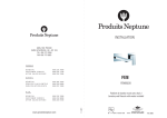
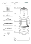
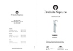
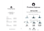
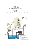
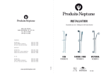
INSTALLATION
6835, RUE PICARD
SAINT-HYACINTHE, QC, J2S 1H3
TEL. 450 773 7058
FAX 450 773 5063
CANADA
GENERAL
CUSTOMER SERVICE
AFTER SALE SERVICE
888 226 7099
888 226 7199
888 226 7599
QUÉBEC
GÉNÉRAL
SERVICE À LA CLIENTÈLE
SERVICE APRÈS-VENTE
888 366 7058
888 226 6899
888 223 1899
U.S.A.
GENERAL
CUSTOMER SERVICE
AFTER SALE SERVICE
888 226 7899
888 226 9099
888 226 9199
FEN
FEN990260
www.produitsneptune.com
06/2014
Valve thermostatique / Thermostatic valve
AT006911P11
REV: 0001
PIÈCES / PARTS
OPERATION
Lire complètement et attentivement le manuel avant de procéder à l’installation pour éviter
les erreurs.
Veuillez vérifier que vous avez toutes les composantes, listées dans le tableau des pièces,
incluses dans votre boîte. Dans le cas où des pièces manqueraient, contactez votre
revendeur immédiatement.
Toujours effectuer un test d’eau avant la fermeture définitive afin de s’assurer de l’absence
de fuites d’eau.
Read this manual fully and carefully before proceeding with the installation to avoid possible
errors.
INSTALLATION
Always conduct a water test before final installation to ensure there are no leaks.
3 5/16" (85mm)
1 3/16" (30mm)
3/4 - 14NPT
1.
2.
3.
The cartridges in the main body have been tested and adjusted by the factory. Do
not take the cartridges apart!
Ensure the water supply line is clear before installation to avoid blockage.
Connect the hot water supply on the left and the cold water supply on the right.
Pressure flow:
Min: 0.05 MP
Max:1.60 MPa
Recommended pressure: 0.1 MPa to 0.8 MPa
Product surface treatments may change without prior notice from the company.
Ø1 3/4"
(44mm)
Ø5 1/8" (130mm)
Min 1 1/2“ (38mm)
Max 2 5/8“ (67mm)
3/4 - 14NPT
3.
1" (25mm)
2.
Les cartouches dans le corps principal ont été examinées et ajustées à l’usine.
Ne démontez pas les cartouches !
Assurez-vous de nettoyer le tuyau d’approvisionnement d’eau avant
l’installation pour éviter le colmatage.
Raccordez l’eau chaude sur le côté gauche et l’eau froide sur le côté droit.
Débit de pression:
min: 0.05 MP
max: 1.60 MPa
Pression recommandée: 0.1 MPa à 0.8 MPa
Les traitements extérieurs du produit peuvent changer, et ce sans préavis du
manufacturier.
3/4 - 14NPT
1.
7 1/4" (185mm)
ATTENTION
3 1/8" (79mm)
Please ensure you have all components, shown on the parts list, included in your box. If
you are missing parts, please notify your retailer immediately.
6" (152mm)
INSTALLATION
Exemple d’installation / Suggested pipping layout
Valider les tolérances de profondeur d’installation (Min-Max) avant d’installer le
corps principal de la valve thermostatique. Le raccorder et s’assurer de l’absence de
fuites avant de fermer le mur.
Verify the min/max dephts before installing the main body of the thermostatic valve.
Connect and ensure there are no leaks before closing the wall.
1
Douchette sur rail
Sliding bar with hand shower
Tête de douche pluie
Rain-style shower head
Raccordement valve d’arrêt
Shut off valve connection
Valve déviatrice
Diverter valve
Jets de corps / Body jets
Entrée eau chaude
Hot water inlet
Sortie d’eau
Water outlet
Entrée eau froide
Cold water inlet
ou / or
Régler adéquatement la température de l’eau avant de positionner la poignée
Appropriate adjustment of the water temperature before positioning the handle
Valve d’arrêt
Shut-off valve
Bec de bain
Bathtub spout
2
Valve thermostatique
Thermostatic valve
2
3
1
Eau chaude
Hot water
Eau froide
Cold water
*Mettre un bouchon sur les sorties d’eau non utilisées de la valve déviatrice.
*Unused water outlets of the diverter valve have to be blocked with a cap.
4
5
6
7
Eau mixée
Mixed water
Vue explosée / Exploded view
1
Liste des pièces / Parts list
No Description FR
Handle
Set screw
1
4
Cache-vis
Plaque de finition ronde
Screw cap
Circular finishing plate
1
1
5
Bague de limitation
Limiting control ring
1
6
Anneau de fixation
Fastening washer
1
7
Cartouche thermostatique
Thermostatic cartridge
1
8
Kit valve d’arrêt
Shut off valve kit
2
9
Cylindre de finition
Finishing cylinder
1
10 Adaptateur 3/4 - 1/2
3/4 - 1/2 adaptator
3
11 Vis
12 Corps principal
13 Cheville
Screw
Main body
Wall plug
2
14 Capuchon de protection
Protective cover
1
2
3
3
4
5
6
7
8
9
10
11
12
13
14
Qté
Qty
Poignée
Vis d’arrêt
1
2
EN Description
1
1
2